EP4534439A1 - Bi-level metal locking cleat - Google Patents
Bi-level metal locking cleat Download PDFInfo
- Publication number
- EP4534439A1 EP4534439A1 EP24202694.6A EP24202694A EP4534439A1 EP 4534439 A1 EP4534439 A1 EP 4534439A1 EP 24202694 A EP24202694 A EP 24202694A EP 4534439 A1 EP4534439 A1 EP 4534439A1
- Authority
- EP
- European Patent Office
- Prior art keywords
- housing
- level
- metal locking
- tie body
- head
- Prior art date
- Legal status (The legal status is an assumption and is not a legal conclusion. Google has not performed a legal analysis and makes no representation as to the accuracy of the status listed.)
- Granted
Links
Images



Classifications
-
- B—PERFORMING OPERATIONS; TRANSPORTING
- B65—CONVEYING; PACKING; STORING; HANDLING THIN OR FILAMENTARY MATERIAL
- B65D—CONTAINERS FOR STORAGE OR TRANSPORT OF ARTICLES OR MATERIALS, e.g. BAGS, BARRELS, BOTTLES, BOXES, CANS, CARTONS, CRATES, DRUMS, JARS, TANKS, HOPPERS, FORWARDING CONTAINERS; ACCESSORIES, CLOSURES, OR FITTINGS THEREFOR; PACKAGING ELEMENTS; PACKAGES
- B65D63/00—Flexible elongated elements, e.g. straps, for bundling or supporting articles
- B65D63/10—Non-metallic straps, tapes, or bands; Filamentary elements, e.g. strings, threads or wires; Joints between ends thereof
- B65D63/14—Joints produced by application of separate securing members
- B65D63/16—Joints using buckles, wedges, or like locking members attached to the end of the element
-
- B—PERFORMING OPERATIONS; TRANSPORTING
- B65—CONVEYING; PACKING; STORING; HANDLING THIN OR FILAMENTARY MATERIAL
- B65D—CONTAINERS FOR STORAGE OR TRANSPORT OF ARTICLES OR MATERIALS, e.g. BAGS, BARRELS, BOTTLES, BOXES, CANS, CARTONS, CRATES, DRUMS, JARS, TANKS, HOPPERS, FORWARDING CONTAINERS; ACCESSORIES, CLOSURES, OR FITTINGS THEREFOR; PACKAGING ELEMENTS; PACKAGES
- B65D63/00—Flexible elongated elements, e.g. straps, for bundling or supporting articles
- B65D63/02—Metallic straps, tapes, or bands; Joints between ends thereof
- B65D63/06—Joints produced by application of separate securing members, e.g. by deformation thereof
- B65D63/08—Joints using buckles, wedges, or like locking members attached to the ends of the elements
-
- F—MECHANICAL ENGINEERING; LIGHTING; HEATING; WEAPONS; BLASTING
- F16—ENGINEERING ELEMENTS AND UNITS; GENERAL MEASURES FOR PRODUCING AND MAINTAINING EFFECTIVE FUNCTIONING OF MACHINES OR INSTALLATIONS; THERMAL INSULATION IN GENERAL
- F16B—DEVICES FOR FASTENING OR SECURING CONSTRUCTIONAL ELEMENTS OR MACHINE PARTS TOGETHER, e.g. NAILS, BOLTS, CIRCLIPS, CLAMPS, CLIPS OR WEDGES; JOINTS OR JOINTING
- F16B2/00—Friction-grip releasable fastenings
- F16B2/02—Clamps, i.e. with gripping action effected by positive means other than the inherent resistance to deformation of the material of the fastening
- F16B2/06—Clamps, i.e. with gripping action effected by positive means other than the inherent resistance to deformation of the material of the fastening external, i.e. with contracting action
- F16B2/065—Clamps, i.e. with gripping action effected by positive means other than the inherent resistance to deformation of the material of the fastening external, i.e. with contracting action using screw-thread elements
-
- F—MECHANICAL ENGINEERING; LIGHTING; HEATING; WEAPONS; BLASTING
- F16—ENGINEERING ELEMENTS AND UNITS; GENERAL MEASURES FOR PRODUCING AND MAINTAINING EFFECTIVE FUNCTIONING OF MACHINES OR INSTALLATIONS; THERMAL INSULATION IN GENERAL
- F16B—DEVICES FOR FASTENING OR SECURING CONSTRUCTIONAL ELEMENTS OR MACHINE PARTS TOGETHER, e.g. NAILS, BOLTS, CIRCLIPS, CLAMPS, CLIPS OR WEDGES; JOINTS OR JOINTING
- F16B2/00—Friction-grip releasable fastenings
- F16B2/02—Clamps, i.e. with gripping action effected by positive means other than the inherent resistance to deformation of the material of the fastening
- F16B2/06—Clamps, i.e. with gripping action effected by positive means other than the inherent resistance to deformation of the material of the fastening external, i.e. with contracting action
- F16B2/08—Clamps, i.e. with gripping action effected by positive means other than the inherent resistance to deformation of the material of the fastening external, i.e. with contracting action using bands
-
- B—PERFORMING OPERATIONS; TRANSPORTING
- B65—CONVEYING; PACKING; STORING; HANDLING THIN OR FILAMENTARY MATERIAL
- B65D—CONTAINERS FOR STORAGE OR TRANSPORT OF ARTICLES OR MATERIALS, e.g. BAGS, BARRELS, BOTTLES, BOXES, CANS, CARTONS, CRATES, DRUMS, JARS, TANKS, HOPPERS, FORWARDING CONTAINERS; ACCESSORIES, CLOSURES, OR FITTINGS THEREFOR; PACKAGING ELEMENTS; PACKAGES
- B65D2563/00—Flexible elongated elements, e.g. straps for bundling or supporting atricles
- B65D2563/10—Non-metallic straps, tapes or bands; Filamentary elements, e.g. strings, threads, wires; Joints between ends thereof
- B65D2563/101—Details of non-metallic straps, tapes or bands
- B65D2563/107—Details of non-metallic straps, tapes or bands having a release mechanism, e.g. reusable bundling straps
Definitions
- the present invention relates to a metal locking cleat, and more particularly to a bi-level metal locking cleat with improved strength.
- FIGS. 1A and 1B illustrate the prior art metal ball locking tie with bi-level head 20.
- the metal locking tie with bi-level head has a high loop tensile strength compared to other metal locking ties.
- the metal ball locking tie with bi-level head is difficult to manufacture.
- a progressive die is required to stamp the bi-level head which would require a number of stamping stations, a large die, and a large press bed. Additionally, threading multiple tie loops through the bi-level head is complicated and too difficult when the metal locking tie is wrapped around a small diameter cable bundle.
- U.S. Patent No. 9,783,350 discloses a metal ball locking tie with an extended support clip.
- the extended support clip provides floor support to the head of the metal ball locking tie to withstand impulse forces.
- Stainless steel strap cable cleats have been used for securing a bundle of cables and for providing short circuit protection.
- the stainless steel strap cable cleats are stronger than metal ball locking ties for a number of reasons.
- the strap body is generally wider and thicker than metal ball locking ties.
- the stainless steel strap can be triple looped during installation instead of just doubled looped.
- the strap body withstands an impulse force, such as a short circuit event or a military application, compared to metal ball locking ties.
- Stainless steel strap cable cleats are challenging to install. Threading the stainless steel strap is difficult especially for small diameter cable bundles. Additionally, tools are required for installation of the stainless steel strap cable cleats and closing the strap buckle is often difficult.
- a metal locking cleat for securing cable bundles has a multi-level housing, a tie body, and a metal locking head.
- the multi-level housing includes a top, a bottom, sides, a front, a back, an upper level, and a lower level.
- the tie body is positioned in the lower level of the housing.
- the metal locking head is positioned in the upper level of the housing.
- the tie body wraps around a cable bundle and through the lower level of the housing for multiple loops. Next, the tie body extends through the upper level of the housing and through the metal locking head to secure the metal locking cleat.
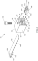
- FIG. 2 is an exploded view of the bi-level metal locking cleat 50 of the present invention.
- the bi-level metal locking cleat 50 includes a stainless steel housing 60, a metal locking head 100, a tie body 130, and a fastener 150.
- the metal locking head 100 and tie body 130 form a standard metal locking tie as described in commonly owned U.S. Patent No. 6,647,596 , herein incorporated by reference.
- FIG. 3 illustrates a perspective view of the housing 60 of the bi-level metal locking cleat 50.
- the housing 60 includes a top wall 62, a bottom wall 64, an open front 66, a partially open back 68, and two sidewalls 70.
- the housing 60 is divided into a lower level 72 and an upper level 80.
- the lower level 72 includes a short lower level floor 74 that is centered between the front 66 and the back 68 of the housing 60.
- the short lower level floor 74 has a body shear form cutout 76 for attachment of the tie body 130.
- the lower level floor 74 is shorter than the upper level 80 to maximize the number of loops of the tie body 130 by controlling the arc peak of the tie body 130 when it is installed in the lower level 72.
- the sidewalls 70 of the housing 60 fully support the upper level 80.
- the back 68 of the upper level 80 is enclosed except for a pass thru slot 82 designed to receive the last loop of the tie body 130 that is then fed through the metal locking head 100.
- the remainder of the back 68 of the upper level 80 of the housing 60 forms a head retainment wall 84 to keep the metal locking head 100 in the housing 60 when the metal locking cleat 50 is under tension.
- the upper level 80 includes an upper level floor 86 with a tie body lock recess 88 that receives the tie body 130 when the fastener 150 is tightened and deforms the tie body 130 (see FIGS. 8 and 9 ).
- the deformed tie body 130 increases the strength of the metal locking cleat 50 and improves resistance to slippage during impulse forces.
- the upper level floor 86 also includes head retainment ribs 90.
- One head retainment rib 90 is positioned on each side of the tie body lock recess 88.
- the head retainment ribs 90 create an interference fit between the metal locking head 100 and the housing 60.
- the top wall 62 of the housing, or the ceiling of the upper level 80, has a threaded fastener hole 92.
- the threaded fastener hole 92 is positioned above the tie body lock recess 88.
- the metal locking head 100 has a roof 102, a ceiling 104, and a bottom wall 106. The bottom wall 106 and ceiling 104 are joined by a pair of sidewalls 108.
- the metal locking head 100 has a strap entry face 110, a strap exit face 112, and a strap receiving aperture 114 extending therebetween.
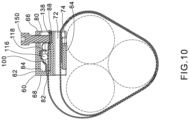
- the metal locking head 100 includes a roller means 116 in the form of a ball or sphere for retaining the tie body 130 within the locking head 100 (see FIG. 10 ).
- the ball 116 is captively held between the roof 102 and the bottom wall 106 by a finger 118 extending from the roof 102 towards the bottom wall 106 adjacent to the strap exit face 112.
- the tie body 130 includes a first end 132, a hooked portion 134, an aperture 136 and a second end 138.
- the tie body 130 could also include a locking tab (not illustrated), if desired.
- FIGS. 4-10 illustrate the assembly of the bi-level metal locking cleat 50 of the present invention.
- the bi-level metal locking cleat 50 requires a small amount of assembly at the factory that includes positioning the metal locking head 100 into the upper level 80 of the housing 60, positioning fastener 150 into the threaded fastener hole 92, and positioning the tie body 130 in the lower level 72 of the housing 60.
- the tie body 130 could also be field installed in the housing, if desired.
- the tie body 130 is positioned in the lower level 72 of the housing 60.
- the tie body 130 is wrapped around the short lower level floor 74 and the bottom wall 64 of the housing 60 (see FIG. 10 ).
- the metal locking head 100 is positioned within the upper level 80 of the housing 60 (see FIG. 5 ).
- the metal locking head 100 is retained in the housing 60 by an interference fit created by the sidewalls 70 and the head retainment ribs 90.
- the final step for initial assembly is that the fastener 150 is positioned within the threaded fastener hole 92 in the top wall 62 of the housing 60 (see FIG. 6 ).
- the tie body 130 is then looped around a cable bundle 160 (see FIG. 9 ) and reinserted in and through the lower level 72 of the housing 60.
- the desired number of tie loops needs to be determined to achieve the required strength of the metal locking cleat 50.
- the last tie loop of the tie body 130 is inserted and pushed through the pass thru slot 82 in the upper level 80 of the housing 60 and through the metal locking head 100.
- the last tie loop of the tie body 130 should be pushed through the metal locking head 100 as far as possible before attaching a flush cut tensioning tool to the second end 138 of the tie body 130.
- the tie body 130 is then tensioned by the tool to the desired tension level and cut flush to the housing 60.
- the housing remains perpendicular to the cable bundle throughout assembly.
- the fastener 150 may be tightened to the desired torque.
- the tie body 130 deforms into the body lock recess 88 in the upper level floor 86 of housing 60 (see FIGS. 8 and 9 ).
- the bi-level metal locking cleat of the present invention provides the required strength to withstand impulse forces.
- the bi-level metal locking cleat is easy to assemble and allows multiple loops of the tie body to achieve the strength requirements.
- the bi-level metal locking cleat can also be easily installed in confined spaces as the tie body of the metal locking cleat is tensioned and cutoff without the need of rotating any tool.
Landscapes
- Engineering & Computer Science (AREA)
- Mechanical Engineering (AREA)
- General Engineering & Computer Science (AREA)
- Supports For Pipes And Cables (AREA)
- Installation Of Indoor Wiring (AREA)
- Clamps And Clips (AREA)
Abstract
Description
- The present invention relates to a metal locking cleat, and more particularly to a bi-level metal locking cleat with improved strength.
- Metallic bundling devices incorporating locking balls and roller pins have been used for bundling bales of cotton or the like since the Nineteenth Century. None of the prior devices were positive locking, i.e., depending on the orientation of the locking head, gravity could hold the ball out of locking engagement with the strap resulting in release.
U.S. Patent No. 4,399,592 addressed this problem by teaching the addition of a raised portion or protuberances for deflecting the threaded strap away from the floor as the threaded strap exits the locking head. This deflection ensures that the locking ball is in continuous engagement with the threaded strap regardless of the position of the ball or the orientation of the locking head. -
U.S. Patent No. 8,635,745 discloses a metal ball locking tie with a bi-level head.FIGS. 1A and 1B illustrate the prior art metal ball locking tie with bi-levelhead 20. The metal locking tie with bi-level head has a high loop tensile strength compared to other metal locking ties. The metal ball locking tie with bi-level head, however, is difficult to manufacture. A progressive die is required to stamp the bi-level head which would require a number of stamping stations, a large die, and a large press bed. Additionally, threading multiple tie loops through the bi-level head is complicated and too difficult when the metal locking tie is wrapped around a small diameter cable bundle. -
U.S. Patent No. 9,783,350 - Stainless steel strap cable cleats (MS 75 straps) have been used for securing a bundle of cables and for providing short circuit protection. The stainless steel strap cable cleats are stronger than metal ball locking ties for a number of reasons. The strap body is generally wider and thicker than metal ball locking ties. The stainless steel strap can be triple looped during installation instead of just doubled looped. Finally, the strap body withstands an impulse force, such as a short circuit event or a military application, compared to metal ball locking ties. Stainless steel strap cable cleats, however, are challenging to install. Threading the stainless steel strap is difficult especially for small diameter cable bundles. Additionally, tools are required for installation of the stainless steel strap cable cleats and closing the strap buckle is often difficult.
- Thus, it would be desirable to provide an improved metal locking cleat for securing a bundle of cables that is easier to install and is capable of withstanding strong impulse forces or short circuit events.
- A metal locking cleat for securing cable bundles is disclosed. The metal locking cleat has a multi-level housing, a tie body, and a metal locking head. The multi-level housing includes a top, a bottom, sides, a front, a back, an upper level, and a lower level. The tie body is positioned in the lower level of the housing. The metal locking head is positioned in the upper level of the housing. To install the metal locking cleat, the tie body wraps around a cable bundle and through the lower level of the housing for multiple loops. Next, the tie body extends through the upper level of the housing and through the metal locking head to secure the metal locking cleat.
-
-
FIG. 1A is a side view of a prior art metal locking tie with a bi-level head. -
FIG. 1B is a perspective view of the metal locking tie with a bi-level head ofFIG. 1 installed around a cable bundle. -
FIG. 2 is an exploded view of the bi-level metal locking cleat of the present invention. -
FIG. 3 is a perspective view of the metal locking cleat housing ofFIG. 2 . -
FIG. 4 is a partially exploded view of the bi-level metal locking cleat ofFIG. 2 with a first end of the tie body installed in the housing. -
FIG. 5 is a partially exploded view of the bi-level metal locking cleat ofFIG. 4 with the metal locking head installed in the housing. -
FIG. 6 is a perspective view of the assembled bi-level metal locking cleat ofFIG. 2 . -
FIG. 7 is a perspective view of the bi-level metal locking cleat ofFIG. 6 with a second end of the tie body fed through the housing and the metal locking head. -
FIG. 8 is a perspective view of the bi-level metal locking cleat ofFIG. 7 with the fastener tightened and the tie body deformed. -
FIG. 9 is a perspective view of the bi-level metal locking cleat ofFIG. 8 wrapped around a cable bundle. -
FIG. 10 is a cross sectional view of the bi-level metal locking cleat ofFIG. 8 taken along line 10-10. -
FIG. 2 is an exploded view of the bi-levelmetal locking cleat 50 of the present invention. The bi-levelmetal locking cleat 50 includes astainless steel housing 60, ametal locking head 100, atie body 130, and afastener 150. Themetal locking head 100 andtie body 130 form a standard metal locking tie as described in commonly ownedU.S. Patent No. 6,647,596 , herein incorporated by reference. -
FIG. 3 illustrates a perspective view of thehousing 60 of the bi-levelmetal locking cleat 50. Thehousing 60 includes atop wall 62, abottom wall 64, anopen front 66, a partiallyopen back 68, and twosidewalls 70. Thehousing 60 is divided into alower level 72 and anupper level 80. - The
lower level 72 includes a shortlower level floor 74 that is centered between thefront 66 and theback 68 of thehousing 60. The shortlower level floor 74 has a bodyshear form cutout 76 for attachment of thetie body 130. Thelower level floor 74 is shorter than theupper level 80 to maximize the number of loops of thetie body 130 by controlling the arc peak of thetie body 130 when it is installed in thelower level 72. - The
sidewalls 70 of thehousing 60 fully support theupper level 80. Theback 68 of theupper level 80 is enclosed except for a pass thruslot 82 designed to receive the last loop of thetie body 130 that is then fed through themetal locking head 100. The remainder of theback 68 of theupper level 80 of thehousing 60 forms ahead retainment wall 84 to keep themetal locking head 100 in thehousing 60 when themetal locking cleat 50 is under tension. - The
upper level 80 includes anupper level floor 86 with a tie body lock recess 88 that receives thetie body 130 when thefastener 150 is tightened and deforms the tie body 130 (seeFIGS. 8 and9 ). Thedeformed tie body 130 increases the strength of themetal locking cleat 50 and improves resistance to slippage during impulse forces. - The
upper level floor 86 also includeshead retainment ribs 90. Onehead retainment rib 90 is positioned on each side of the tie body lock recess 88. Thehead retainment ribs 90 create an interference fit between themetal locking head 100 and thehousing 60. Thetop wall 62 of the housing, or the ceiling of theupper level 80, has a threadedfastener hole 92. The threadedfastener hole 92 is positioned above the tiebody lock recess 88. - The
metal locking head 100 has aroof 102, aceiling 104, and abottom wall 106. Thebottom wall 106 andceiling 104 are joined by a pair ofsidewalls 108. Themetal locking head 100 has astrap entry face 110, astrap exit face 112, and astrap receiving aperture 114 extending therebetween. Themetal locking head 100 includes a roller means 116 in the form of a ball or sphere for retaining thetie body 130 within the locking head 100 (seeFIG. 10 ). Theball 116 is captively held between theroof 102 and thebottom wall 106 by afinger 118 extending from theroof 102 towards thebottom wall 106 adjacent to thestrap exit face 112. Thetie body 130 includes afirst end 132, a hookedportion 134, anaperture 136 and asecond end 138. Thetie body 130 could also include a locking tab (not illustrated), if desired. -
FIGS. 4-10 illustrate the assembly of the bi-levelmetal locking cleat 50 of the present invention. The bi-levelmetal locking cleat 50 requires a small amount of assembly at the factory that includes positioning themetal locking head 100 into theupper level 80 of thehousing 60,positioning fastener 150 into the threadedfastener hole 92, and positioning thetie body 130 in thelower level 72 of thehousing 60. Thetie body 130 could also be field installed in the housing, if desired. As illustrated inFIG. 4 , thetie body 130 is positioned in thelower level 72 of thehousing 60. Thetie body 130 is wrapped around the shortlower level floor 74 and thebottom wall 64 of the housing 60 (seeFIG. 10 ). Themetal locking head 100 is positioned within theupper level 80 of the housing 60 (seeFIG. 5 ). Themetal locking head 100 is retained in thehousing 60 by an interference fit created by thesidewalls 70 and thehead retainment ribs 90. The final step for initial assembly is that thefastener 150 is positioned within the threadedfastener hole 92 in thetop wall 62 of the housing 60 (seeFIG. 6 ). - The
tie body 130 is then looped around a cable bundle 160 (seeFIG. 9 ) and reinserted in and through thelower level 72 of thehousing 60. The desired number of tie loops needs to be determined to achieve the required strength of themetal locking cleat 50. Once the desired number of tie loops of thetie body 130 has been achieved, the last tie loop of thetie body 130 is inserted and pushed through the pass thruslot 82 in theupper level 80 of thehousing 60 and through themetal locking head 100. The last tie loop of thetie body 130 should be pushed through themetal locking head 100 as far as possible before attaching a flush cut tensioning tool to thesecond end 138 of thetie body 130. Thetie body 130 is then tensioned by the tool to the desired tension level and cut flush to thehousing 60. The housing remains perpendicular to the cable bundle throughout assembly. Once thetie body 130 has been tensioned, thefastener 150 may be tightened to the desired torque. As thefastener 150 is tightened, thetie body 130 deforms into thebody lock recess 88 in theupper level floor 86 of housing 60 (seeFIGS. 8 and9 ). - The bi-level metal locking cleat of the present invention provides the required strength to withstand impulse forces. The bi-level metal locking cleat is easy to assemble and allows multiple loops of the tie body to achieve the strength requirements. The bi-level metal locking cleat can also be easily installed in confined spaces as the tie body of the metal locking cleat is tensioned and cutoff without the need of rotating any tool.
- Furthermore, while the particular preferred embodiments of the present invention have been shown and described, it will be obvious to those skilled in the art that changes and modifications may be made without departing from the teaching of the invention. The matter set forth in the foregoing description and accompanying drawings is offered by way of illustration only and not as limitation. The actual scope of the invention is intended to be defined in the following claims when viewed in their proper perspective.
Claims (14)
- A metal locking cleat for securing cable bundles, the metal locking cleat comprising:a housing having a top, a bottom, sides, a front, a back, an upper level, and a lower level;a tie body positioned in the lower level of the housing; anda metal locking head positioned in the upper level of the housing;whereby the tie body wraps around a cable bundle and through the lower level of the housing, through the upper level of the housing, and through the metal locking head to secure the metal locking cleat.
- The metal locking cleat of claim 1, wherein the lower level of the housing has a short lower level floor centered between the front of the housing and the back of the housing,
optionally wherein the short lower level floor is shorter than the upper level of the housing. - The metal locking cleat of any preceding claim, wherein the housing further comprises a fastener hole in the top of the housing for receiving a fastener to engage the tie body fed through the metal locking head.
- The metal locking cleat of any preceding claim, wherein the upper level of the housing has an upper level floor with a tie body lock recess,optionally wherein the housing has a threaded fastener hole in the top of the housing for receiving a fastener, whereby the tightened fastener deforms the tie body into the tie body lock recess,further optionally wherein the deformed tie body increases the strength of the metal locking cleat and improves resistance to slippage.
- The metal locking cleat of any preceding claim, wherein the back of the housing has a pass thru slot into the upper level for receiving the tie body.
- The metal locking cleat of any preceding claim, wherein the upper level of the housing has a head retainment wall along the back of the housing for maintaining the metal locking head in the housing.
- The metal locking cleat of any preceding claim, wherein the upper level of the housing has head retainment ribs positioned on a floor of the upper level, the head retainment ribs provide an interference fit for the metal locking head positioned in the housing.
- A metal locking cleat assembly comprising:a multi-level housing having a top, a bottom, sides, a front, a back, an upper level, and a lower level;a tie body having a first end and a second end, the first end of the tie body wrapped around the lower level of the multi-level housing;a metal locking head positioned within the upper level of the multi-level housing; anda fastener installed through the top of the multi-level housing;whereby the tie body wraps around a cable bundle and through the lower level of the multi-level housing, through the upper level of the multi-level housing, and through the metal locking head to secure the metal locking cleat assembly.
- The metal locking cleat assembly of claim 8, wherein the lower level of the multi-level housing has a short lower level floor centered between the front of the multi-level housing and the back of the multi-level housing,
optionally wherein the short lower level floor is shorter than the upper level of the multi-level housing. - The metal locking cleat assembly of any of claims 8 to 9, wherein the fastener engages the second end of the tie body fed through the metal locking head,optionally wherein the upper level of the housing has an upper level floor with a tie body lock recess, whereby tightening the fastener deforms the second end of the tie body into the tie body lock recess,further optionally wherein the deformed second end of the tie body increases the strength of the metal locking cleat assembly and improves resistance to slippage.
- The metal locking cleat assembly of any of claims 8 to 10, wherein the housing further comprising a threaded fastener hole in the top of the housing for receiving the fastener to engage the tie body fed through the metal locking head.
- The metal locking cleat assembly of any of claims 8 to 11, wherein the back of the multi-level housing has a pass thru slot leading into the upper level of the multi-level housing for receiving the tie body.
- The metal locking cleat assembly of any of claims 8 to 12, wherein the upper level of the multi-level housing has a head retainment wall along the back of the multi-level housing for maintaining the metal locking head in the multi-level housing.
- The metal locking cleat assembly of any of claims 8 to 13, wherein the upper level of the multi-level housing has head retainment ribs positioned on a floor of the upper level, the head retainment ribs provide an interference fit for the metal locking head positioned in the multi-level housing.
Applications Claiming Priority (1)
| Application Number | Priority Date | Filing Date | Title |
|---|---|---|---|
| US18/376,670 US12304711B2 (en) | 2023-10-04 | 2023-10-04 | Bi-level metal locking cleat |
Publications (2)
| Publication Number | Publication Date |
|---|---|
| EP4534439A1 true EP4534439A1 (en) | 2025-04-09 |
| EP4534439B1 EP4534439B1 (en) | 2026-04-08 |
Family
ID=92909562
Family Applications (1)
| Application Number | Title | Priority Date | Filing Date |
|---|---|---|---|
| EP24202694.6A Active EP4534439B1 (en) | 2023-10-04 | 2024-09-25 | Bi-level metal locking cleat |
Country Status (3)
| Country | Link |
|---|---|
| US (1) | US12304711B2 (en) |
| EP (1) | EP4534439B1 (en) |
| KR (1) | KR20250049181A (en) |
Citations (6)
| Publication number | Priority date | Publication date | Assignee | Title |
|---|---|---|---|---|
| US230313A (en) * | 1880-07-20 | Laughlin | ||
| US4399592A (en) | 1980-12-08 | 1983-08-23 | Panduit Corp. | Metal tie |
| KR20010046034A (en) * | 1999-11-10 | 2001-06-05 | 배준집 | A removable tie |
| US6647596B1 (en) | 2002-05-02 | 2003-11-18 | Panduit Corp. | Ball lock cable tie having a strap aperture |
| US8635745B2 (en) | 2010-11-23 | 2014-01-28 | Panduit Corp. | Metal locking tie |
| US9783350B2 (en) | 2013-05-06 | 2017-10-10 | Panduit Corp. | Extended support clip for a metal locking tie |
Family Cites Families (14)
| Publication number | Priority date | Publication date | Assignee | Title |
|---|---|---|---|---|
| US1053684A (en) | 1910-06-22 | 1913-02-18 | John C Vogel | Ground-joint clamp. |
| US3015865A (en) | 1960-05-24 | 1962-01-09 | John J Rapuzzi | Universal inserted ball type buckle |
| FR1267912A (en) | 1960-06-15 | 1961-07-28 | Method and apparatus for re-tensioning a band hoop after strapping | |
| US3530544A (en) * | 1967-10-30 | 1970-09-29 | Thomas & Betts Corp | Cable bundling strap |
| US3528142A (en) | 1968-05-31 | 1970-09-15 | Band It Co | Worm screw clamp |
| US3754303A (en) | 1972-03-30 | 1973-08-28 | Ideal Corp | High compression band clamp |
| US4473925A (en) | 1982-07-12 | 1984-10-02 | Houdaille Industries, Inc. | Band clamp |
| US4646393A (en) | 1985-07-25 | 1987-03-03 | Electro Adapter, Inc. | Clamping band for electromagnetic shielding band cable connector |
| US4868953A (en) | 1987-03-11 | 1989-09-26 | Thomas & Betts Corporation | Environmental bundling tie |
| US4887334A (en) | 1988-03-10 | 1989-12-19 | Band-It-Idex, Inc. | Clamping assembly with side entry connection of a clamp unit to a band |
| EP2219802B1 (en) | 2007-11-02 | 2013-05-29 | Band-It-IDEX, Inc. | Dual locking band clamp |
| WO2016029930A1 (en) | 2014-08-26 | 2016-03-03 | Oetiker Schweiz Ag | Band clamp |
| US9637291B2 (en) * | 2015-03-26 | 2017-05-02 | Raul Eduardo Montejo | Multi-positional closure fastener |
| US11472616B2 (en) * | 2020-07-29 | 2022-10-18 | Panduit Corp. | Metal ball locking tie assembly including cushion |
-
2023
- 2023-10-04 US US18/376,670 patent/US12304711B2/en active Active
-
2024
- 2024-09-23 KR KR1020240128028A patent/KR20250049181A/en active Pending
- 2024-09-25 EP EP24202694.6A patent/EP4534439B1/en active Active
Patent Citations (6)
| Publication number | Priority date | Publication date | Assignee | Title |
|---|---|---|---|---|
| US230313A (en) * | 1880-07-20 | Laughlin | ||
| US4399592A (en) | 1980-12-08 | 1983-08-23 | Panduit Corp. | Metal tie |
| KR20010046034A (en) * | 1999-11-10 | 2001-06-05 | 배준집 | A removable tie |
| US6647596B1 (en) | 2002-05-02 | 2003-11-18 | Panduit Corp. | Ball lock cable tie having a strap aperture |
| US8635745B2 (en) | 2010-11-23 | 2014-01-28 | Panduit Corp. | Metal locking tie |
| US9783350B2 (en) | 2013-05-06 | 2017-10-10 | Panduit Corp. | Extended support clip for a metal locking tie |
Also Published As
| Publication number | Publication date |
|---|---|
| KR20250049181A (en) | 2025-04-11 |
| EP4534439B1 (en) | 2026-04-08 |
| US20250115403A1 (en) | 2025-04-10 |
| US12304711B2 (en) | 2025-05-20 |
Similar Documents
| Publication | Publication Date | Title |
|---|---|---|
| US8281461B2 (en) | Button head tie | |
| US7930805B2 (en) | Retained tension multiple ball lock cable tie | |
| EP0065543B1 (en) | Metal tie | |
| US7603751B2 (en) | Displacement lock MLT | |
| US8250716B2 (en) | Retained tension metal locking tie with 360 degree seal | |
| US4473925A (en) | Band clamp | |
| US6647596B1 (en) | Ball lock cable tie having a strap aperture | |
| US5884367A (en) | Self-locking cable tie strap with a symmetrical structure | |
| US6578239B2 (en) | Low profile latchable tie | |
| EP2643234B1 (en) | Metal locking tie | |
| EP1359357B1 (en) | Ball lock cable tie | |
| EP0438878A1 (en) | Bundle tie | |
| EP1384929B1 (en) | Ball lock cable tie having stiffening ribs | |
| CA1073640A (en) | Cable strap | |
| US12304711B2 (en) | Bi-level metal locking cleat | |
| WO2011080511A1 (en) | Tie | |
| US12398828B2 (en) | Slotted bolt cleat binder | |
| JP2002181138A (en) | Rope ring bracket | |
| AU539762B2 (en) | Metal tie | |
| EP1590258A1 (en) | Strap | |
| JP2000009108A (en) | Improved cable tie | |
| AU7899081A (en) | Metal tie | |
| JPH06191551A (en) | Cable tie |
Legal Events
| Date | Code | Title | Description |
|---|---|---|---|
| PUAI | Public reference made under article 153(3) epc to a published international application that has entered the european phase |
Free format text: ORIGINAL CODE: 0009012 |
|
| STAA | Information on the status of an ep patent application or granted ep patent |
Free format text: STATUS: THE APPLICATION HAS BEEN PUBLISHED |
|
| AK | Designated contracting states |
Kind code of ref document: A1 Designated state(s): AL AT BE BG CH CY CZ DE DK EE ES FI FR GB GR HR HU IE IS IT LI LT LU LV MC ME MK MT NL NO PL PT RO RS SE SI SK SM TR |
|
| STAA | Information on the status of an ep patent application or granted ep patent |
Free format text: STATUS: REQUEST FOR EXAMINATION WAS MADE |
|
| 17P | Request for examination filed |
Effective date: 20250815 |
|
| GRAP | Despatch of communication of intention to grant a patent |
Free format text: ORIGINAL CODE: EPIDOSNIGR1 |
|
| STAA | Information on the status of an ep patent application or granted ep patent |
Free format text: STATUS: GRANT OF PATENT IS INTENDED |
|
| RIC1 | Information provided on ipc code assigned before grant |
Ipc: B65D 63/08 20060101AFI20251119BHEP |
|
| INTG | Intention to grant announced |
Effective date: 20251222 |
|
| GRAS | Grant fee paid |
Free format text: ORIGINAL CODE: EPIDOSNIGR3 |
|
| GRAA | (expected) grant |
Free format text: ORIGINAL CODE: 0009210 |
|
| STAA | Information on the status of an ep patent application or granted ep patent |
Free format text: STATUS: THE PATENT HAS BEEN GRANTED |
|
| AK | Designated contracting states |
Kind code of ref document: B1 Designated state(s): AL AT BE BG CH CY CZ DE DK EE ES FI FR GB GR HR HU IE IS IT LI LT LU LV MC ME MK MT NL NO PL PT RO RS SE SI SK SM TR |
|
| REG | Reference to a national code |
Ref country code: CH Ref legal event code: F10 Free format text: ST27 STATUS EVENT CODE: U-0-0-F10-F00 (AS PROVIDED BY THE NATIONAL OFFICE) Effective date: 20260408 Ref country code: GB Ref legal event code: FG4D |
|
| REG | Reference to a national code |
Ref country code: DE Ref legal event code: R096 Ref document number: 602024003820 Country of ref document: DE |