EP4534386A1 - Steering column for vehicle and vehicle - Google Patents
Steering column for vehicle and vehicle Download PDFInfo
- Publication number
- EP4534386A1 EP4534386A1 EP23881337.2A EP23881337A EP4534386A1 EP 4534386 A1 EP4534386 A1 EP 4534386A1 EP 23881337 A EP23881337 A EP 23881337A EP 4534386 A1 EP4534386 A1 EP 4534386A1
- Authority
- EP
- European Patent Office
- Prior art keywords
- energy absorption
- adjustment
- sub
- drive
- steering column
- Prior art date
- Legal status (The legal status is an assumption and is not a legal conclusion. Google has not performed a legal analysis and makes no representation as to the accuracy of the status listed.)
- Pending
Links
Images


Classifications
-
- B—PERFORMING OPERATIONS; TRANSPORTING
- B62—LAND VEHICLES FOR TRAVELLING OTHERWISE THAN ON RAILS
- B62D—MOTOR VEHICLES; TRAILERS
- B62D1/00—Steering controls, i.e. means for initiating a change of direction of the vehicle
- B62D1/02—Steering controls, i.e. means for initiating a change of direction of the vehicle vehicle-mounted
- B62D1/16—Steering columns
- B62D1/18—Steering columns yieldable or adjustable, e.g. tiltable
-
- B—PERFORMING OPERATIONS; TRANSPORTING
- B62—LAND VEHICLES FOR TRAVELLING OTHERWISE THAN ON RAILS
- B62D—MOTOR VEHICLES; TRAILERS
- B62D1/00—Steering controls, i.e. means for initiating a change of direction of the vehicle
- B62D1/02—Steering controls, i.e. means for initiating a change of direction of the vehicle vehicle-mounted
- B62D1/16—Steering columns
- B62D1/18—Steering columns yieldable or adjustable, e.g. tiltable
- B62D1/19—Steering columns yieldable or adjustable, e.g. tiltable incorporating energy-absorbing arrangements, e.g. by being yieldable or collapsible
- B62D1/197—Steering columns yieldable or adjustable, e.g. tiltable incorporating energy-absorbing arrangements, e.g. by being yieldable or collapsible incorporating devices for preventing ingress of the steering column into the passengers space in case of accident
-
- B—PERFORMING OPERATIONS; TRANSPORTING
- B62—LAND VEHICLES FOR TRAVELLING OTHERWISE THAN ON RAILS
- B62D—MOTOR VEHICLES; TRAILERS
- B62D1/00—Steering controls, i.e. means for initiating a change of direction of the vehicle
- B62D1/02—Steering controls, i.e. means for initiating a change of direction of the vehicle vehicle-mounted
- B62D1/16—Steering columns
- B62D1/18—Steering columns yieldable or adjustable, e.g. tiltable
- B62D1/181—Steering columns yieldable or adjustable, e.g. tiltable with power actuated adjustment, e.g. with position memory
-
- B—PERFORMING OPERATIONS; TRANSPORTING
- B62—LAND VEHICLES FOR TRAVELLING OTHERWISE THAN ON RAILS
- B62D—MOTOR VEHICLES; TRAILERS
- B62D1/00—Steering controls, i.e. means for initiating a change of direction of the vehicle
- B62D1/02—Steering controls, i.e. means for initiating a change of direction of the vehicle vehicle-mounted
- B62D1/16—Steering columns
- B62D1/18—Steering columns yieldable or adjustable, e.g. tiltable
- B62D1/185—Steering columns yieldable or adjustable, e.g. tiltable adjustable by axial displacement, e.g. telescopically
-
- B—PERFORMING OPERATIONS; TRANSPORTING
- B62—LAND VEHICLES FOR TRAVELLING OTHERWISE THAN ON RAILS
- B62D—MOTOR VEHICLES; TRAILERS
- B62D1/00—Steering controls, i.e. means for initiating a change of direction of the vehicle
- B62D1/02—Steering controls, i.e. means for initiating a change of direction of the vehicle vehicle-mounted
- B62D1/16—Steering columns
- B62D1/18—Steering columns yieldable or adjustable, e.g. tiltable
- B62D1/187—Steering columns yieldable or adjustable, e.g. tiltable with tilt adjustment; with tilt and axial adjustment
- B62D1/189—Steering columns yieldable or adjustable, e.g. tiltable with tilt adjustment; with tilt and axial adjustment the entire column being tiltable as a unit
-
- B—PERFORMING OPERATIONS; TRANSPORTING
- B62—LAND VEHICLES FOR TRAVELLING OTHERWISE THAN ON RAILS
- B62D—MOTOR VEHICLES; TRAILERS
- B62D1/00—Steering controls, i.e. means for initiating a change of direction of the vehicle
- B62D1/02—Steering controls, i.e. means for initiating a change of direction of the vehicle vehicle-mounted
- B62D1/16—Steering columns
- B62D1/18—Steering columns yieldable or adjustable, e.g. tiltable
- B62D1/19—Steering columns yieldable or adjustable, e.g. tiltable incorporating energy-absorbing arrangements, e.g. by being yieldable or collapsible
-
- B—PERFORMING OPERATIONS; TRANSPORTING
- B62—LAND VEHICLES FOR TRAVELLING OTHERWISE THAN ON RAILS
- B62D—MOTOR VEHICLES; TRAILERS
- B62D1/00—Steering controls, i.e. means for initiating a change of direction of the vehicle
- B62D1/02—Steering controls, i.e. means for initiating a change of direction of the vehicle vehicle-mounted
- B62D1/16—Steering columns
- B62D1/18—Steering columns yieldable or adjustable, e.g. tiltable
- B62D1/19—Steering columns yieldable or adjustable, e.g. tiltable incorporating energy-absorbing arrangements, e.g. by being yieldable or collapsible
- B62D1/192—Yieldable or collapsible columns
-
- B—PERFORMING OPERATIONS; TRANSPORTING
- B62—LAND VEHICLES FOR TRAVELLING OTHERWISE THAN ON RAILS
- B62D—MOTOR VEHICLES; TRAILERS
- B62D1/00—Steering controls, i.e. means for initiating a change of direction of the vehicle
- B62D1/02—Steering controls, i.e. means for initiating a change of direction of the vehicle vehicle-mounted
- B62D1/16—Steering columns
- B62D1/18—Steering columns yieldable or adjustable, e.g. tiltable
- B62D1/19—Steering columns yieldable or adjustable, e.g. tiltable incorporating energy-absorbing arrangements, e.g. by being yieldable or collapsible
- B62D1/195—Yieldable supports for the steering column
-
- F—MECHANICAL ENGINEERING; LIGHTING; HEATING; WEAPONS; BLASTING
- F16—ENGINEERING ELEMENTS AND UNITS; GENERAL MEASURES FOR PRODUCING AND MAINTAINING EFFECTIVE FUNCTIONING OF MACHINES OR INSTALLATIONS; THERMAL INSULATION IN GENERAL
- F16F—SPRINGS; SHOCK-ABSORBERS; MEANS FOR DAMPING VIBRATION
- F16F7/00—Vibration-dampers; Shock-absorbers
- F16F7/12—Vibration-dampers; Shock-absorbers using plastic deformation of members
- F16F7/123—Deformation involving a bending action, e.g. strap moving through multiple rollers, folding of members
-
- F—MECHANICAL ENGINEERING; LIGHTING; HEATING; WEAPONS; BLASTING
- F16—ENGINEERING ELEMENTS AND UNITS; GENERAL MEASURES FOR PRODUCING AND MAINTAINING EFFECTIVE FUNCTIONING OF MACHINES OR INSTALLATIONS; THERMAL INSULATION IN GENERAL
- F16F—SPRINGS; SHOCK-ABSORBERS; MEANS FOR DAMPING VIBRATION
- F16F7/00—Vibration-dampers; Shock-absorbers
- F16F7/12—Vibration-dampers; Shock-absorbers using plastic deformation of members
- F16F7/125—Units with a telescopic-like action as one member moves into, or out of a second member
-
- F—MECHANICAL ENGINEERING; LIGHTING; HEATING; WEAPONS; BLASTING
- F16—ENGINEERING ELEMENTS AND UNITS; GENERAL MEASURES FOR PRODUCING AND MAINTAINING EFFECTIVE FUNCTIONING OF MACHINES OR INSTALLATIONS; THERMAL INSULATION IN GENERAL
- F16F—SPRINGS; SHOCK-ABSORBERS; MEANS FOR DAMPING VIBRATION
- F16F7/00—Vibration-dampers; Shock-absorbers
- F16F7/12—Vibration-dampers; Shock-absorbers using plastic deformation of members
- F16F7/128—Vibration-dampers; Shock-absorbers using plastic deformation of members characterised by the members, e.g. a flat strap, yielding through stretching, pulling apart
Definitions
- the present disclosure relates to the field of vehicle technologies, and more particularly, to a steering column for a vehicle and a vehicle.
- the steering column is designed with a shrinkable energy absorption structure to protect the driver during a collision.
- an existing shrinkable energy absorption structure is complicated, costly to assemble and maintain, and may cause the steering column to drop during the collision, leading to secondary injuries to the driver.
- the present disclosure aims to solve at least one of the technical problems in the related art to some extent.
- the present disclosure provides a steering column for a vehicle, which can reduce severity of driver injuries during a collision and improve safety performance of the steering column.
- the present disclosure further provides a vehicle having the steering column as described above.
- the steering column for the vehicle includes a first mounting plate, an adjustment plate, an upper column, an adjustment mechanism, and an energy absorption mechanism.
- the adjustment plate is movably connected to the first mounting plate in a first direction.
- the upper column is fixed to the adjustment plate.
- the adjustment mechanism includes a drive portion and a first adjustment portion.
- the drive portion is fixed to the first mounting plate and configured to drive the first adjustment portion to move in the first direction.
- the energy absorption mechanism includes an energy absorption block and an energy absorption strip.
- the energy absorption block is fixedly connected to the adjustment plate and the first adjustment portion.
- the energy absorption block internally has an energy absorption groove extending in a curved shape.
- the energy absorption strip has an end passing through the energy absorption groove and fixed to the first adjustment portion and another end extending in the first direction.
- the energy absorption groove is movable along the energy absorption strip in the first direction when an impact force borne by the adjustment plate reaches a predetermined threshold.
- the upper column, the adjustment plate, and the energy absorption groove may move away from a driver.
- the energy absorption groove may deform the energy absorption strip to absorb impact energy.
- the energy absorption strip may also prevent the upper column and the adjustment plate from falling downwards, to reduce the severity of driver injuries and improve the safety performance of the steering column.
- the energy absorption block includes a body portion and a connection arm.
- the body portion is fixed to the adjustment plate.
- the energy absorption groove is formed in the body portion.
- the connection arm is connected to the body portion and fixedly connected to the first adjustment portion.
- a weakening structure is formed at a joint between the connection arm and the body portion and located at a side of the first adjustment portion facing towards the adjustment plate.
- the weakening structure has a thinning groove.
- a length direction of the thinning groove is perpendicular to the first direction and parallel to the adjustment plate.
- the weakening structure has a plurality of weakening holes arranged in a direction perpendicular to the first direction and parallel to the adjustment plate.
- the adjustment plate has a mounting recess.
- the body portion is at least partially disposed in the mounting recess.
- the body portion includes a first sub-portion and a second sub-portion.
- the energy absorption groove is formed in the first sub-portion and has a side opening formed at a side surface of the first sub-portion, and the second sub-portion is adapted to be fixedly connected to the first sub-portion to block the side opening.
- the side surface of the first sub-portion is perpendicular to the energy absorption groove.
- one of the first sub-portion and the second sub-portion is provided with a positioning pin; and another one of the first sub-portion and the second sub-portion has a positioning hole adapted to be engaged with the positioning pin.
- the steering column further includes a second mounting plate.
- the first mounting plate is movably connected to the second mounting plate in the first direction.
- the adjustment mechanism further includes a second lead screw fixed to the second mounting plate.
- the first adjustment portion is a nut.
- the drive portion includes a drive motor, a drive box, and a first lead screw.
- the drive motor is fixed to the first mounting plate through the drive box.
- the drive box is in a transmission connection with the drive motor, the second lead screw, and the first lead screw.
- the drive motor is configured to drive the first adjustment portion to move in the first direction by means of the drive box and the first lead screw, and the drive motor is further configured to drive the drive box to move along the second lead screw in the first direction.
- the energy adsorption strip is a steel strip.
- a vehicle according to an embodiment of another aspect of the present disclosure includes the steering column as described above.
- the upper column, the adjustment plate, and the energy absorption groove may move away from the driver.
- the energy absorption groove may deform the energy absorption strip to absorb the impact energy.
- the energy absorption strip may also prevent the upper column and the adjustment plate from falling downwards, to reduce the severity of driver injuries and improve the safety performance of the vehicle.
- orientation or position relationship indicated by terms such as “length”, “width”, “thickness”, “over”, “below”, “in”, and “out” is based on the orientation or position relationship illustrated in the accompanying drawings, and is merely for the convenience of describing the present disclosure and simplifying the description, rather than indicating or implying that the associated device or element must have a specific orientation, or be constructed and operated in a specific orientation, and therefore cannot be understood as a limitation on the present disclosure.
- first and second are only used for descriptive purposes, and cannot be understood as indicating or implying relative importance or implicitly indicating the number of indicated technical features. Therefore, the feature associated with “first” and “second” may include one or more this feature distinctly or implicitly.
- plural means at least two, such as two, three, etc.
- a steering column 10 for a vehicle is described in detail with reference to FIG. 1 to FIG. 5 .
- the steering column 10 for the vehicle includes a first mounting plate 1, an adjustment plate 2, an upper column 3, an adjustment mechanism 4, and an energy absorption mechanism 5.
- the energy absorption groove 5111 is movable along the energy absorption strip 52 in the first direction, allowing the energy absorption strip 52 to be deformed and absorb energy. In this way, during a vehicle collision, the upper column 3 and the adjustment plate 2 may move away from the driver, and impact energy is absorbed by the deformation of the energy absorption strip 52 to reduce severity of driver injuries.
- the driver impacts the steering wheel due to inertia.
- the steering wheel, the upper column 3, and the adjustment plate 2 are rigidly connected to one another.
- An impact force generated by the driver's impact on the steering wheel is directed to a side of the first direction, i.e., a side away from the driver in the first direction.
- the adjustment plate 2 and the energy absorption block 51 connected to the adjustment plate 2 tend to move towards the side of the first direction.
- the first adjustment portion 45 is fixed to the first mounting plate 1 through the drive portion.
- the energy absorption groove 5111 moves from a fixed end of the energy absorption strip 52 to a free end of the energy absorption strip 52.
- the energy absorption strip 52 continuously deforms and absorbs the impact force, thus playing a role of buffering and guiding to reduce the severity of the driver injuries.
- the energy absorption strip 52 may also play a role of flexibly connecting the adjustment plate 2 and the first adjustment portion 45 to prevent the upper column 3 and the adjustment plate 2 from falling down in a gravity direction, avoiding secondary injuries to driver's legs caused by the upper column 3 and the adjustment plate 2.
- the upper column 3, the adjustment plate 2, and the energy absorption groove 5111 may move away from the driver.
- the energy absorption groove 5111 may deform the energy absorption strip 52 to absorb the impact energy. Meanwhile, the energy absorption strip 52 may also prevent the upper column 3 and the adjustment plate 2 from falling downwards, to reduce the severity of driver injuries and improve safety performance of the steering column 10.
- the energy absorption block 51 includes a body portion 511 and a connection arm 512.
- the body portion 511 is fixed to the adjustment plate 2.
- the energy absorption groove 5111 is formed in the body portion 511.
- the connection arm 512 is connected to the body portion 511.
- the connection arm 512 is also fixedly connected to the first adjustment portion 45.
- a weakening structure 513 is formed at a joint between the connection arm 512 and the body portion 511.
- the weakening structure 513 is located at a side of the first adjustment portion 45 facing towards the adjustment plate 2. That is, in the first direction, a projection of the weakening structure 513 is located between the first adjustment portion 45 and the adjustment plate 2.
- the body portion 511 When the impact force borne by the adjustment plate 2 reaches the predetermined threshold, the body portion 511 is separated from the connection arm 512 at the weakening structure 513. Moreover, the body portion 511 moves along the energy absorption strip 52. When the energy absorption groove 5111 in the body portion 511 moves along the energy absorption strip 52, the energy absorption strip 52 deforms and absorbs energy, realizing an energy absorption effect.
- the predetermined threshold is smaller than a maximum acting force that is exerted by a steering manipulation apparatus on a human body specified in the national standard ( GB11557 , the stipulation protecting drivers from being injured by motor vehicle steering mechanism), to protect the driver during the collision. Moreover, the predetermined threshold is greater than a pressure of the driver on the upper column 3 during normal use, to avoid damage of the energy absorption block 51 during the normal use. In some embodiments, the predetermined threshold ranges from 1KN to 10KN.
- the weakening structure 513 includes a thinning groove.
- the thinning groove may reduce a thickness of a joint between the connection arm 512 and the body portion 511 to weaken a connection strength between the connection arm 512 and the body portion 511.
- the body portion 511 and the connection arm 512 may be separated from each other at the thinning groove when the impact force borne by the adjustment plate 2 reaches the predetermined threshold.
- the body portion 511 is connected to the connection arm 512.
- a length direction of the thinning groove is perpendicular to the first direction and parallel to the adjustment plate 2, to ensure a weaken effect of the thinning groove on the connection strength between the connection arm 512 and the body portion 511.
- the weakening structure 513 includes a plurality of weakening holes, which may be through holes or blind holes.
- the plurality of weakening holes may weaken the connection strength between the connection arm 512 and the body portion 511.
- the body portion 511 and the connection arm 512 are separated from each other at the plurality of weakening holes when the impact force borne by the adjustment plate 2 reaches the predetermined threshold.
- the body portion 511 is connected to the connection arm 512.
- the plurality of weakening holes is arranged in a direction perpendicular to the first direction and parallel to the adjustment plate 2, to ensure weaken effects of the plurality of weakening holes on the connection strength between the connection arm 512 and the body portion 511.
- the body portion 511 includes a first sub-portion 5112 and a second sub-portion 5113.
- the energy absorption groove 5111 is formed in the first sub-portion 5112.
- the connection arm 512 may be connected to the first sub-portion 5112.
- the energy absorption groove 5111 has a side opening 5114 formed at a side surface of the first sub-portion 5112.
- the second sub-portion 5113 is adapted to be fixedly connected to the first sub-portion 5112 to block the side opening 5114.
- the side surface of the first sub-portion 5112 is perpendicular to the energy absorption groove 5111.
- the energy absorption strip 52 can be mounted from the side opening 5114 into the energy absorption groove 5111 extending in a curved shape. Subsequently, the second sub-portion 5113 is fixedly combined with the first sub-portion 5112, to allow the second sub-portion 5113 to block the side opening 5114, making it beneficial to assembly of the energy absorption strip 52 with the body portion 511.
- the first sub-portion 5112 has two positioning pins 5115 spaced apart from each other at the side surface of the first sub-portion 5112 having the side opening 5114.
- the second sub-portion 5113 correspondingly has two positioning holes 5116 formed thereon. Each of the two positioning holes 5116 is engaged with a corresponding one of the two positioning pins 5115 in a positioning manner.
- the body portion 511 may be fixedly connected to the adjustment plate 2 by the fastener 9.
- the first sub-portion 5112 is provided with a first mounting table 5117.
- the first mounting table 5117 is adapted to be lapped at an outer edge of the mounting recess.
- the first mounting table 5117 has at least one third mounting hole 5118 formed thereon and may be fixed to the adjustment plate 2 by the fastener 9 passing through the third mounting hole 5118.
- the second sub-portion 5113 is provided with a second mounting table 5119.
- the first mounting table 5117 and the second mounting table 5119 are located at two opposite sides of the body portion 511, respectively.
- the second mounting table 5119 is adapted to be lapped at the outer edge of the mounting recess.
- the second mounting table 5119 has at least one fourth mounting hole 5120 formed thereon and may be fixed to the adjustment plate 2 by the fastener 9 passing through the fourth mounting hole 5120.
- the fastener 9 may be a bolt or a rivet.
- the energy absorption mechanism 5 is damaged.
- the energy absorption mechanism 5 is detachably connected to the first adjustment portion 45 and the adjustment plate 2 through the fastener 9, respectively.
- Maintenance of the steering column 10 may be completed only by replacing the energy absorption block 51 and the energy absorption strip 52 after a minor collision of the vehicle occurs.
- the energy absorption block 51 and the energy absorption strip 52 has simple processing processes, low production costs, and are easy and quick to mount and remove, making it beneficial to a reduction in maintenance costs of the steering column 10.
- the steering column 10 further includes a second mounting plate 6 adapted to be fixed to a vehicle body of the vehicle.
- the second mounting plate 6 is fixed to an instrument beam of the vehicle.
- the first mounting plate 1 is movably connected to the second mounting plate 6 in the first direction.
- the first mounting plate 1 and the second mounting plate 6 may be connected to each other by a linear bearing.
- the adjustment mechanism 4 further includes a second lead screw 46.
- the second lead screw 46 is fixed to the second mounting plate 6.
- the first adjustment portion 45 is a nut.
- the drive portion includes a drive motor 41, a drive box, and a first lead screw 44.
- the drive motor 41 is fixed to the first mounting plate 1 through the drive box.
- the drive box is in a transmission connection with the drive motor 41, the second lead screw 46, and the first lead screw 44.
- the drive motor 41 is configured to drive the first adjustment portion 45 to move in the first direction by means of the drive box and the first lead screw 44.
- the drive motor 41 is further configured to drive the drive box to move along the second lead screw 46 in the first direction. Therefore, position adjustment efficiency of the upper column 3 can be improved, and a space occupied by the steering column 10 can be reduced.
- the drive box is internally provided with a driving gear, a first driven gear 42, and a second driven gear 43. Both the first driven gear 42 and the second driven gear 43 are in a transmission connection with the driving gear, and the drive motor 41 may drive the driving gear to rotate, to drive the first driven gear 42 and the second driven gear 43 to rotate through the driving gear.
- a planetary transmission device is further provided between the drive motor 41 and the driving gear. Power outputted by the motor drives the driving gear to rotate after being reduced in speed and increased in torque by the planetary transmission device.
- the drive box is further internally provided with an idler gear. The driving gear, the first driven gear 42, and the second driven gear 43 are all engaged with the idler gear.
- the second lead screw 46 penetrates the drive box and the second driven gear 43.
- the second driven gear 43 is threadedly engaged with the second lead screw 46.
- the drive box may be driven to move along the second lead screw 46 in the first direction.
- a movement direction of the drive box is the same as a movement direction of the first adjustment portion 45.
- both the drive motor 41 and the first mounting plate 1 are connected to the drive box, and the drive motor 41 and the first mounting plate 1 both move synchronously with the drive box, i.e., the drive portion may drive the adjustment plate 2 and the first mounting plate 1 to move synchronously in the first direction.
- an adjustable range of the upper column 3 in the first direction can be increased in a limited space.
- the adjustment efficiency of the upper column 3 is improved.
- the energy absorption strip 52 is a steel strip, i.e., the energy absorption strip 52 is made of a steel material.
- the steel strip is low in cost, easy to process, and good in deformation and energy absorption effects. According to energy absorption requirements, it is possible to adjust a size of the energy absorption groove 5111 and set a length, a thickness, rigidity, and other parameters of the corresponding steel strip, to satisfy design requirements for shrinkable forces and shrinkable distances of different vehicle models.
- the energy absorption block 51 has an energy absorption groove 5111 extending in a curved shape.
- the energy absorption groove 5111 follows a path similar to an "L" shape.
- the energy absorption strip 52 includes a fixed segment 521, a mounting segment 522, and a free segment 523.
- the fixed segment 521 is connected to the free segment 523 through the mounting segment 522.
- the fixed segment 521 is located outside the energy absorption groove 5111 and is adapted to be connected to the first adjustment portion 45.
- the mounting segment 522 is located inside the energy absorption groove 5111 and shaped to match with the energy absorption groove 5111.
- the free segment 523 is located outside the mounting recess and extends in the first direction.
- the energy absorption strip 52 may provide buffering and guiding effects for the sliding of the energy absorption groove 5111, while also preventing the steering wheel and the upper column 3 from slipping out of the instrument beam and impacting driver's body.
- the upper column 3, the adjustment plate 2, and the energy absorption groove 5111 may move away from the driver.
- the energy absorption groove 5111 may deform the energy absorption strip 52 to absorb the impact energy.
- the energy absorption strip 52 may also prevent the upper column 3 and the adjustment plate 2 from falling downwards, to reduce the severity of the driver injuries and improve the safety performance of the vehicle.
Landscapes
- Engineering & Computer Science (AREA)
- Mechanical Engineering (AREA)
- Chemical & Material Sciences (AREA)
- Combustion & Propulsion (AREA)
- Transportation (AREA)
- General Engineering & Computer Science (AREA)
- Steering Controls (AREA)
Abstract
Description
- This application claims priority to
Chinese Patent Application No. 202211304450.0, entitled "STEERING COLUMN FOR VEHICLE AND VEHICLE" and filed on October 24, 2022 - The present disclosure relates to the field of vehicle technologies, and more particularly, to a steering column for a vehicle and a vehicle.
- With the continuous development of vehicle technologies, vehicle safety has been widely concerned by people. When a vehicle collision occurs, a steering column and a steering wheel on the steering column are easy to cause injuries to a driver.
- In the related art, the steering column is designed with a shrinkable energy absorption structure to protect the driver during a collision. However, an existing shrinkable energy absorption structure is complicated, costly to assemble and maintain, and may cause the steering column to drop during the collision, leading to secondary injuries to the driver.
- The present disclosure aims to solve at least one of the technical problems in the related art to some extent. To this end, the present disclosure provides a steering column for a vehicle, which can reduce severity of driver injuries during a collision and improve safety performance of the steering column.
- The present disclosure further provides a vehicle having the steering column as described above.
- The steering column for the vehicle according to embodiments of the present disclosure includes a first mounting plate, an adjustment plate, an upper column, an adjustment mechanism, and an energy absorption mechanism. The adjustment plate is movably connected to the first mounting plate in a first direction. The upper column is fixed to the adjustment plate. The adjustment mechanism includes a drive portion and a first adjustment portion. The drive portion is fixed to the first mounting plate and configured to drive the first adjustment portion to move in the first direction. The energy absorption mechanism includes an energy absorption block and an energy absorption strip. The energy absorption block is fixedly connected to the adjustment plate and the first adjustment portion. The energy absorption block internally has an energy absorption groove extending in a curved shape. The energy absorption strip has an end passing through the energy absorption groove and fixed to the first adjustment portion and another end extending in the first direction. The energy absorption groove is movable along the energy absorption strip in the first direction when an impact force borne by the adjustment plate reaches a predetermined threshold.
- With the steering column for the vehicle according to the embodiments of the present disclosure, when a collision occurs, the upper column, the adjustment plate, and the energy absorption groove may move away from a driver. The energy absorption groove may deform the energy absorption strip to absorb impact energy. Meanwhile, the energy absorption strip may also prevent the upper column and the adjustment plate from falling downwards, to reduce the severity of driver injuries and improve the safety performance of the steering column.
- According to some embodiments of the present disclosure, the energy absorption block includes a body portion and a connection arm. The body portion is fixed to the adjustment plate. The energy absorption groove is formed in the body portion. The connection arm is connected to the body portion and fixedly connected to the first adjustment portion. A weakening structure is formed at a joint between the connection arm and the body portion and located at a side of the first adjustment portion facing towards the adjustment plate. When the impact force borne by the adjustment plate reaches the predetermined threshold, the body portion is separated from the connection arm at the weakening structure and moves along the energy absorption strip.
- According to some embodiments of the present disclosure, the weakening structure has a thinning groove. A length direction of the thinning groove is perpendicular to the first direction and parallel to the adjustment plate.
- According to some embodiments of the present disclosure, the weakening structure has a plurality of weakening holes arranged in a direction perpendicular to the first direction and parallel to the adjustment plate.
- According to some embodiments of the present disclosure, the adjustment plate has a mounting recess. The body portion is at least partially disposed in the mounting recess.
- According to some embodiments of the present disclosure, the body portion includes a first sub-portion and a second sub-portion. The energy absorption groove is formed in the first sub-portion and has a side opening formed at a side surface of the first sub-portion, and the second sub-portion is adapted to be fixedly connected to the first sub-portion to block the side opening. The side surface of the first sub-portion is perpendicular to the energy absorption groove.
- According to some embodiments of the present disclosure, one of the first sub-portion and the second sub-portion is provided with a positioning pin; and another one of the first sub-portion and the second sub-portion has a positioning hole adapted to be engaged with the positioning pin.
- According to some embodiments of the present disclosure, the steering column further includes a second mounting plate. The first mounting plate is movably connected to the second mounting plate in the first direction. The adjustment mechanism further includes a second lead screw fixed to the second mounting plate. The first adjustment portion is a nut. The drive portion includes a drive motor, a drive box, and a first lead screw. The drive motor is fixed to the first mounting plate through the drive box. The drive box is in a transmission connection with the drive motor, the second lead screw, and the first lead screw. The drive motor is configured to drive the first adjustment portion to move in the first direction by means of the drive box and the first lead screw, and the drive motor is further configured to drive the drive box to move along the second lead screw in the first direction.
- According to an embodiment of the present disclosure, the energy adsorption strip is a steel strip.
- A vehicle according to an embodiment of another aspect of the present disclosure includes the steering column as described above.
- With the vehicle according to the embodiments of the present disclosure, when a collision occurs, the upper column, the adjustment plate, and the energy absorption groove may move away from the driver. The energy absorption groove may deform the energy absorption strip to absorb the impact energy. Meanwhile, the energy absorption strip may also prevent the upper column and the adjustment plate from falling downwards, to reduce the severity of driver injuries and improve the safety performance of the vehicle.
- Additional aspects and advantages of the present disclosure will be in part set forth below, become apparent in part from the following description, or can be learned by practice of the present disclosure.
-
-
FIG. 1 is a schematic view of a steering column according to an embodiment of the present disclosure. -
FIG. 2 is a partially enlarged view at an energy absorption mechanism inFIG. 1 . -
FIG. 3 is a schematic view of an energy absorption mechanism according to an embodiment of the present disclosure. -
FIG. 4 is an exploded view of an energy absorption block according to an embodiment of the present disclosure. -
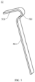
FIG. 5 is a schematic view of an energy absorption strip according to an embodiment of the present disclosure. - Reference numerals:
first mounting plate 1,adjustment plate 2,upper column 3,adjustment mechanism 4,drive motor 41, first drivengear 42, second drivengear 43,first lead screw 44,first adjustment portion 45,second lead screw 46,energy absorption mechanism 5,energy absorption block 51, body portion 511,energy absorption groove 5111,first sub-portion 5112,second sub-portion 5113,side opening 5114,positioning pin 5115,positioning hole 5116, first mounting table 5117,third mounting hole 5118, second mounting table 5119,fourth mounting hole 5120,connection arm 512,first mounting hole 5121, weakeningstructure 513,energy absorption strip 52,fixed segment 521,mounting segment 522,free segment 523,second mounting plate 6, fastener 9,steering column 10. - The embodiments of the present disclosure will be described in detail below, examples thereof are illustrated in the accompanying drawings, throughout which same or similar elements, or elements having same or similar functions, are denoted by same or similar reference numerals. The embodiments described below with reference to the accompanying drawings are exemplary, only used to explain the present disclosure, and should not be construed as limitation of the present disclosure.
- In the description of the present disclosure, it needs to be understood that, orientation or position relationship indicated by terms such as "length", "width", "thickness", "over", "below", "in", and "out" is based on the orientation or position relationship illustrated in the accompanying drawings, and is merely for the convenience of describing the present disclosure and simplifying the description, rather than indicating or implying that the associated device or element must have a specific orientation, or be constructed and operated in a specific orientation, and therefore cannot be understood as a limitation on the present disclosure.
- In addition, terms such as "first" and "second" are only used for descriptive purposes, and cannot be understood as indicating or implying relative importance or implicitly indicating the number of indicated technical features. Therefore, the feature associated with "first" and "second" may include one or more this feature distinctly or implicitly. In the description of the present disclosure, unless otherwise specifically defined, "plurality" means at least two, such as two, three, etc.
- In the present disclosure, unless otherwise clearly specified and limited, terms such as "install", "connect", "connect to", "fix", and the like should be understood in a broad sense. For example, it may be a fixed connection or a detachable connection or connection as one piece; mechanical connection or electrical connection or communication; direct connection or indirect connection through an intermediate; internal communication of two components or the interaction relationship between two components. For those of ordinary skill in the art, the specific meanings of the above terms in the present disclosure can be interpreted depending on specific situations.
- A
steering column 10 for a vehicle according to the embodiments of the present disclosure is described in detail with reference toFIG. 1 to FIG. 5 . - Referring to
FIG. 1 to FIG. 5 , thesteering column 10 for the vehicle includes afirst mounting plate 1, anadjustment plate 2, anupper column 3, anadjustment mechanism 4, and anenergy absorption mechanism 5. - The
adjustment plate 2 is movably connected to the first mountingplate 1 in a first direction. Thefirst mounting plate 1 and theadjustment plate 2 may be connected to each other by a linear bearing. Theupper column 3 is fixed to theadjustment plate 2. The first direction may be an axial direction of theupper column 3. An upper end of theupper column 3 is connected to a steering wheel of the vehicle. Theadjustment plate 2 may be moved to change a position of the upper end of theupper column 3, realizing a position adjustment of the steering wheel. - The
adjustment mechanism 4 includes a drive portion and afirst adjustment portion 45. The drive portion is fixed to the first mountingplate 1 and configured to drive thefirst adjustment portion 45 to move in the first direction. Thefirst adjustment portion 45 may drive theadjustment plate 2 to move relative to the first mountingplate 1 in the first direction, further realizing position adjustments of theupper column 3 and the steering wheel. - The
energy absorption mechanism 5 includes anenergy absorption block 51 and anenergy absorption strip 52. Theenergy absorption block 51 is fixedly connected to theadjustment plate 2 and thefirst adjustment portion 45. Theenergy absorption block 51 internally has anenergy absorption groove 5111 extending in a curved shape. Theenergy absorption groove 5111 has a groove segment bent in the first direction. In some embodiments, theenergy absorption groove 5111 includes a groove segment of a semicircular arc shape or a groove segment of a sinusoidal shape. Theenergy absorption strip 52 has an end passing through theenergy absorption groove 5111 and fixed to thefirst adjustment portion 45 and another end extending in the first direction. - During the position adjustment of the
upper column 3, the drive portion drives thefirst adjustment portion 45 to move in the first direction. Each of theenergy absorption block 51 and theenergy absorption strip 52 is fixedly connected to thefirst adjustment portion 45, theadjustment plate 2 is fixedly connected to thefirst adjustment portion 45 through theenergy absorption block 51, and theupper column 3 is fixedly connected to theadjustment plate 2. Therefore, thefirst adjustment portion 45 can drive theenergy absorption block 51, theenergy absorption strip 52, theadjustment plate 2, and theupper column 3 to move synchronously in the first direction to achieve normal height adjustments of theupper column 3 and the steering wheel, satisfying driver's manipulation comfort requirements. - When an impact force borne by the
adjustment plate 2 reaches a predetermined threshold, theenergy absorption groove 5111 is movable along theenergy absorption strip 52 in the first direction, allowing theenergy absorption strip 52 to be deformed and absorb energy. In this way, during a vehicle collision, theupper column 3 and theadjustment plate 2 may move away from the driver, and impact energy is absorbed by the deformation of theenergy absorption strip 52 to reduce severity of driver injuries. - In some embodiments, when a vehicle collision occurs, the driver impacts the steering wheel due to inertia. The steering wheel, the
upper column 3, and theadjustment plate 2 are rigidly connected to one another. An impact force generated by the driver's impact on the steering wheel is directed to a side of the first direction, i.e., a side away from the driver in the first direction. When the impact force is transferred to theadjustment plate 2, theadjustment plate 2 and theenergy absorption block 51 connected to theadjustment plate 2 tend to move towards the side of the first direction. Thefirst adjustment portion 45 is fixed to the first mountingplate 1 through the drive portion. Thefirst adjustment portion 45 prevents a movement of theadjustment plate 2 by theenergy absorption block 51, causing theenergy absorption block 51 to bear a shear force and be fractured, resulting in failure of a rigid connection between theadjustment plate 2 and thefirst adjustment portion 45. Theadjustment plate 2 drives a part of theenergy absorption block 51 having theenergy absorption groove 5111 to move towards the side of the first direction. At this time, since the end of theenergy absorption strip 52 passing through theenergy absorption groove 5111 is fixed to thefirst adjustment portion 45, theenergy absorption groove 5111 moves towards the side of the first direction along theenergy absorption strip 52 in the first direction. In other words, theenergy absorption groove 5111 moves from a fixed end of theenergy absorption strip 52 to a free end of theenergy absorption strip 52. When theenergy absorption groove 5111 extending in a curved shape moves along theenergy absorption strip 52, theenergy absorption strip 52 continuously deforms and absorbs the impact force, thus playing a role of buffering and guiding to reduce the severity of the driver injuries. In addition, after theenergy absorption block 51 is fractured, theenergy absorption strip 52 may also play a role of flexibly connecting theadjustment plate 2 and thefirst adjustment portion 45 to prevent theupper column 3 and theadjustment plate 2 from falling down in a gravity direction, avoiding secondary injuries to driver's legs caused by theupper column 3 and theadjustment plate 2. - With the
steering column 10 for the vehicle according to the embodiments of the present disclosure, during a collision, theupper column 3, theadjustment plate 2, and theenergy absorption groove 5111 may move away from the driver. Theenergy absorption groove 5111 may deform theenergy absorption strip 52 to absorb the impact energy. Meanwhile, theenergy absorption strip 52 may also prevent theupper column 3 and theadjustment plate 2 from falling downwards, to reduce the severity of driver injuries and improve safety performance of thesteering column 10. - In some embodiments of the present disclosure, referring to
FIG. 1 to FIG. 4 , theenergy absorption block 51 includes a body portion 511 and aconnection arm 512. The body portion 511 is fixed to theadjustment plate 2. Theenergy absorption groove 5111 is formed in the body portion 511. Theconnection arm 512 is connected to the body portion 511. Theconnection arm 512 is also fixedly connected to thefirst adjustment portion 45. A weakeningstructure 513 is formed at a joint between theconnection arm 512 and the body portion 511. The weakeningstructure 513 is located at a side of thefirst adjustment portion 45 facing towards theadjustment plate 2. That is, in the first direction, a projection of the weakeningstructure 513 is located between thefirst adjustment portion 45 and theadjustment plate 2. When the impact force borne by theadjustment plate 2 reaches the predetermined threshold, the body portion 511 is separated from theconnection arm 512 at the weakeningstructure 513. Moreover, the body portion 511 moves along theenergy absorption strip 52. When theenergy absorption groove 5111 in the body portion 511 moves along theenergy absorption strip 52, theenergy absorption strip 52 deforms and absorbs energy, realizing an energy absorption effect. The predetermined threshold is smaller than a maximum acting force that is exerted by a steering manipulation apparatus on a human body specified in the national standard (GB11557 upper column 3 during normal use, to avoid damage of theenergy absorption block 51 during the normal use. In some embodiments, the predetermined threshold ranges from 1KN to 10KN. - In some embodiments of the present disclosure, referring to
FIG. 2 to FIG. 4 , at least a part of the body portion 511 and theconnection arm 512 are integrally formed. The body portion 511 and theconnection arm 512 may be a structural element made of plastic, such as PA (Polyamide) plastic. Theconnection arm 512 and theenergy absorption strip 52 may be fixedly connected to thefirst adjustment portion 45 through a fastener 9. In some embodiments, theconnection arm 512 may have afirst mounting hole 5121 formed thereon. A second mounting hole corresponding to thefirst mounting hole 5121 may be formed at the end of theenergy absorption strip 52 passing through theenergy absorption groove 5111. The fastener 9 may be fixed to thefirst adjustment portion 45 after passing through thefirst mounting hole 5121 and the second mounting hole. The fastener 9 may be a bolt or a rivet. - In some embodiments of the present disclosure, referring to
FIG. 4 , the weakeningstructure 513 includes a thinning groove. The thinning groove may reduce a thickness of a joint between theconnection arm 512 and the body portion 511 to weaken a connection strength between theconnection arm 512 and the body portion 511. By controlling parameters such as a width and a depth of the thinning groove, the body portion 511 and theconnection arm 512 may be separated from each other at the thinning groove when the impact force borne by theadjustment plate 2 reaches the predetermined threshold. When the impact force borne by theadjustment plate 2 does not reach the predetermined threshold, the body portion 511 is connected to theconnection arm 512. A length direction of the thinning groove is perpendicular to the first direction and parallel to theadjustment plate 2, to ensure a weaken effect of the thinning groove on the connection strength between theconnection arm 512 and the body portion 511. - In other embodiments of the present disclosure, the weakening
structure 513 includes a plurality of weakening holes, which may be through holes or blind holes. The plurality of weakening holes may weaken the connection strength between theconnection arm 512 and the body portion 511. By controlling parameters such as a quantity of weakening holes, a hole diameter size, and a hole depth, the body portion 511 and theconnection arm 512 are separated from each other at the plurality of weakening holes when the impact force borne by theadjustment plate 2 reaches the predetermined threshold. When the impact force borne by theadjustment plate 2 does not reach the predetermined threshold, the body portion 511 is connected to theconnection arm 512. The plurality of weakening holes is arranged in a direction perpendicular to the first direction and parallel to theadjustment plate 2, to ensure weaken effects of the plurality of weakening holes on the connection strength between theconnection arm 512 and the body portion 511. - In some embodiments of the present disclosure, the
adjustment plate 2 has a mounting recess. An opening of the mounting recess may face towards thefirst adjustment portion 45. The body portion 511 is at least partially disposed in the mounting recess. The mounting recess may be used for improving a connection strength between the body portion 511 and theadjustment plate 2. When the body portion 511 moves along theenergy absorption strip 52, at least one side wall of the mounting recess may abut against thefirst adjustment portion 45, to prevent the body portion 511 from being separated from theadjustment plate 2. - In some embodiments of the present disclosure, as illustrated in
FIG. 2 to FIG. 5 , the body portion 511 includes afirst sub-portion 5112 and asecond sub-portion 5113. Theenergy absorption groove 5111 is formed in thefirst sub-portion 5112. Theconnection arm 512 may be connected to thefirst sub-portion 5112. Theenergy absorption groove 5111 has aside opening 5114 formed at a side surface of thefirst sub-portion 5112. Thesecond sub-portion 5113 is adapted to be fixedly connected to thefirst sub-portion 5112 to block theside opening 5114. The side surface of thefirst sub-portion 5112 is perpendicular to theenergy absorption groove 5111. Therefore, theenergy absorption strip 52 can be mounted from theside opening 5114 into theenergy absorption groove 5111 extending in a curved shape. Subsequently, thesecond sub-portion 5113 is fixedly combined with thefirst sub-portion 5112, to allow thesecond sub-portion 5113 to block theside opening 5114, making it beneficial to assembly of theenergy absorption strip 52 with the body portion 511. - In some embodiments of the present disclosure, one of the
first sub-portion 5112 and thesecond sub-portion 5113 is provided with apositioning pin 5115, and another one of thefirst sub-portion 5112 and thesecond sub-portion 5113 has apositioning hole 5116 adapted to be engaged with thepositioning pin 5115, to facilitate positioning of thefirst sub-portion 5112 and thesecond sub-portion 5113 when fixedly connected to each other. One or more pairs ofpositioning pin 5115 andpositioning hole 5116 may be provided. - In an embodiment of the present disclosure, as illustrated in
FIG. 4 , thefirst sub-portion 5112 has twopositioning pins 5115 spaced apart from each other at the side surface of thefirst sub-portion 5112 having theside opening 5114. Thesecond sub-portion 5113 correspondingly has twopositioning holes 5116 formed thereon. Each of the twopositioning holes 5116 is engaged with a corresponding one of the twopositioning pins 5115 in a positioning manner. - In another embodiment of the present disclosure (not shown), the
second sub-portion 5113 is provided with twopositioning pins 5115 at a side surface of thesecond sub-portion 5113 blocking theside opening 5114. Thefirst sub-portion 5112 correspondingly has twopositioning holes 5116 formed thereon. Each of the twopositioning pins 5115 is engaged with a corresponding one of the twopositioning holes 5116 in a positioning manner. - In some embodiments of the present disclosure, referring to
FIG. 2 to FIG. 4 , the body portion 511 may be fixedly connected to theadjustment plate 2 by the fastener 9. In some embodiments, thefirst sub-portion 5112 is provided with a first mounting table 5117. The first mounting table 5117 is adapted to be lapped at an outer edge of the mounting recess. The first mounting table 5117 has at least onethird mounting hole 5118 formed thereon and may be fixed to theadjustment plate 2 by the fastener 9 passing through thethird mounting hole 5118. Thesecond sub-portion 5113 is provided with a second mounting table 5119. The first mounting table 5117 and the second mounting table 5119 are located at two opposite sides of the body portion 511, respectively. The second mounting table 5119 is adapted to be lapped at the outer edge of the mounting recess. The second mounting table 5119 has at least onefourth mounting hole 5120 formed thereon and may be fixed to theadjustment plate 2 by the fastener 9 passing through thefourth mounting hole 5120. The fastener 9 may be a bolt or a rivet. - It can be understood that after a vehicle collision occurs, the
energy absorption mechanism 5 is damaged. Theenergy absorption mechanism 5 is detachably connected to thefirst adjustment portion 45 and theadjustment plate 2 through the fastener 9, respectively. Maintenance of thesteering column 10 may be completed only by replacing theenergy absorption block 51 and theenergy absorption strip 52 after a minor collision of the vehicle occurs. Moreover, theenergy absorption block 51 and theenergy absorption strip 52 has simple processing processes, low production costs, and are easy and quick to mount and remove, making it beneficial to a reduction in maintenance costs of thesteering column 10. - In some embodiments of the present disclosure, referring to
FIG. 1 , thesteering column 10 further includes asecond mounting plate 6 adapted to be fixed to a vehicle body of the vehicle. For example, thesecond mounting plate 6 is fixed to an instrument beam of the vehicle. Thefirst mounting plate 1 is movably connected to thesecond mounting plate 6 in the first direction. Thefirst mounting plate 1 and thesecond mounting plate 6 may be connected to each other by a linear bearing. Theadjustment mechanism 4 further includes asecond lead screw 46. Thesecond lead screw 46 is fixed to thesecond mounting plate 6. Thefirst adjustment portion 45 is a nut. The drive portion includes adrive motor 41, a drive box, and afirst lead screw 44. Thedrive motor 41 is fixed to the first mountingplate 1 through the drive box. The drive box is in a transmission connection with thedrive motor 41, thesecond lead screw 46, and thefirst lead screw 44. Thedrive motor 41 is configured to drive thefirst adjustment portion 45 to move in the first direction by means of the drive box and thefirst lead screw 44. Thedrive motor 41 is further configured to drive the drive box to move along thesecond lead screw 46 in the first direction. Therefore, position adjustment efficiency of theupper column 3 can be improved, and a space occupied by thesteering column 10 can be reduced. - In some embodiments, the drive box is internally provided with a driving gear, a first driven
gear 42, and a second drivengear 43. Both the first drivengear 42 and the second drivengear 43 are in a transmission connection with the driving gear, and thedrive motor 41 may drive the driving gear to rotate, to drive the first drivengear 42 and the second drivengear 43 to rotate through the driving gear. In some embodiments, a planetary transmission device is further provided between thedrive motor 41 and the driving gear. Power outputted by the motor drives the driving gear to rotate after being reduced in speed and increased in torque by the planetary transmission device. Meanwhile, the drive box is further internally provided with an idler gear. The driving gear, the first drivengear 42, and the second drivengear 43 are all engaged with the idler gear. The driving gear drives the first drivengear 42 and the second drivengear 43 to rotate through the idler gear. The idler gear may increase distances among axes of the driving gear, the first drivengear 42, and the second drivengear 43, to facilitate the arrangement of thefirst lead screw 44, thesecond lead screw 46, and thedrive motor 41. - The
first lead screw 44 penetrates the drive box and the first drivengear 42. The first drivengear 42 is engaged with the first lead screw rod in a limiting manner. The first drivengear 42 may drive thefirst lead screw 44 to rotate. Thefirst lead screw 44 when rotating may drive thefirst adjustment portion 45 to move in the first direction. - The
second lead screw 46 penetrates the drive box and the second drivengear 43. The second drivengear 43 is threadedly engaged with thesecond lead screw 46. When the second drivengear 43 rotates, the drive box may be driven to move along thesecond lead screw 46 in the first direction. Moreover, a movement direction of the drive box is the same as a movement direction of thefirst adjustment portion 45. Meanwhile, both thedrive motor 41 and the first mountingplate 1 are connected to the drive box, and thedrive motor 41 and the first mountingplate 1 both move synchronously with the drive box, i.e., the drive portion may drive theadjustment plate 2 and the first mountingplate 1 to move synchronously in the first direction. In this way, an adjustable range of theupper column 3 in the first direction can be increased in a limited space. In addition, the adjustment efficiency of theupper column 3 is improved. - In some embodiments of the present disclosure, the
energy absorption strip 52 is a steel strip, i.e., theenergy absorption strip 52 is made of a steel material. The steel strip is low in cost, easy to process, and good in deformation and energy absorption effects. According to energy absorption requirements, it is possible to adjust a size of theenergy absorption groove 5111 and set a length, a thickness, rigidity, and other parameters of the corresponding steel strip, to satisfy design requirements for shrinkable forces and shrinkable distances of different vehicle models. - Referring to
FIG. 4 andFIG. 5 , theenergy absorption block 51 has anenergy absorption groove 5111 extending in a curved shape. Theenergy absorption groove 5111 follows a path similar to an "L" shape. Theenergy absorption strip 52 includes a fixedsegment 521, a mountingsegment 522, and afree segment 523. The fixedsegment 521 is connected to thefree segment 523 through the mountingsegment 522. The fixedsegment 521 is located outside theenergy absorption groove 5111 and is adapted to be connected to thefirst adjustment portion 45. The mountingsegment 522 is located inside theenergy absorption groove 5111 and shaped to match with theenergy absorption groove 5111. Thefree segment 523 is located outside the mounting recess and extends in the first direction. When a collision occurs, the steering wheel, theupper column 3, theadjustment plate 2, and the part of theenergy absorption block 51 having theenergy absorption groove 5111 move synchronously. Theenergy absorption groove 5111 slides on thefree segment 523. Thefree segment 523 deforms and absorbs energy within theenergy absorption groove 5111. Theenergy absorption strip 52 may provide buffering and guiding effects for the sliding of theenergy absorption groove 5111, while also preventing the steering wheel and theupper column 3 from slipping out of the instrument beam and impacting driver's body. - A vehicle according to an embodiment of another aspect of the present disclosure includes the
steering column 10 in the above embodiments. - With the vehicle according to the embodiments of the present disclosure, during a collision, the
upper column 3, theadjustment plate 2, and theenergy absorption groove 5111 may move away from the driver. Theenergy absorption groove 5111 may deform theenergy absorption strip 52 to absorb the impact energy. Meanwhile, theenergy absorption strip 52 may also prevent theupper column 3 and theadjustment plate 2 from falling downwards, to reduce the severity of the driver injuries and improve the safety performance of the vehicle. - In descriptions of the present disclosure, descriptions with reference to the terms "an embodiment", "some embodiments", "examples", "specific examples", or "some examples" etc., mean that specific features, structure, materials, or characteristics described in conjunction with the embodiment or example are included in at least one embodiment or example of the present disclosure. In this specification, the schematic representations of the above terms do not necessarily refer to the same embodiment or example. Moreover, the described specific features, structures, materials or characteristics may be combined in any one or more embodiments or examples in a suitable manner. In addition, those skilled in the art can combine the different embodiments or examples and the features of the different embodiments or examples described in this specification.
- Although the embodiments of the present disclosure have been shown and described above, it can be understood the above-mentioned embodiments are exemplary and should not be construed as limiting the present disclosure. For those skilled in the art, changes, modifications, replacements, and variations can be made to the above-mentioned embodiments within the scope of the present disclosure.
Claims (10)
- A steering column for a vehicle, the steering column comprising:a first mounting plate;an adjustment plate movably connected to the first mounting plate in a first direction;an upper column fixed to the adjustment plate;an adjustment mechanism comprising a drive portion and a first adjustment portion, the drive portion being fixed to the first mounting plate and configured to drive the first adjustment portion to move in the first direction; andan energy absorption mechanism comprising an energy absorption block and an energy absorption strip, the energy absorption block being fixedly connected to the adjustment plate and the first adjustment portion, the energy absorption block internally having an energy absorption groove extending in a curved shape, the energy absorption strip having an end passing through the energy absorption groove and fixed to the first adjustment portion and another end extending in the first direction, and the energy absorption groove being movable along the energy absorption strip in the first direction when an impact force borne by the adjustment plate reaches a predetermined threshold.
- The steering column according to claim 1, wherein the energy absorption block comprises:a body portion; anda connection arm, wherein:the body portion is fixed to the adjustment plate;the energy absorption groove is formed in the body portion;the connection arm is connected to the body portion and fixedly connected to the first adjustment portion;a weakening structure is formed at a joint between the connection arm and the body portion and located at a side of the first adjustment portion facing towards the adjustment plate; andwhen the impact force borne by the adjustment plate reaches the predetermined threshold, the body portion is separated from the connection arm at the weakening structure and moves along the energy absorption strip.
- The steering column according to claim 2, wherein the weakening structure has a thinning groove, a length direction of the thinning groove being perpendicular to the first direction and parallel to the adjustment plate.
- The steering column according to claim 2, wherein the weakening structure has a plurality of weakening holes arranged in a direction perpendicular to the first direction and parallel to the adjustment plate.
- The steering column according to any one of claims 2 to 4, wherein the adjustment plate has a mounting recess, the body portion being at least partially disposed in the mounting recess.
- The steering column according to any one of claims 2 to 5, wherein the body portion comprises a first sub-portion and a second sub-portion, the energy absorption groove being formed in the first sub-portion and having a side opening formed at a side surface of the first sub-portion, and the second sub-portion being adapted to be fixedly connected to the first sub-portion to block the side opening, wherein the side surface of the first sub-portion is perpendicular to the energy absorption groove.
- The steering column according to claim 6, wherein:one of the first sub-portion and the second sub-portion is provided with a positioning pin; andanother one of the first sub-portion and the second sub-portion has a positioning hole adapted to be engaged with the positioning pin.
- The steering column according to any one of claims 1 to 7, further comprising a second mounting plate, the first mounting plate being movably connected to the second mounting plate in the first direction, wherein:the adjustment mechanism further comprises a second lead screw fixed to the second mounting plate;the first adjustment portion is a nut; andthe drive portion comprises a drive motor, a drive box, and a first lead screw, the drive motor being fixed to the first mounting plate through the drive box, the drive box being in a transmission connection with the drive motor, the second lead screw, and the first lead screw, the drive motor being configured to drive the first adjustment portion to move in the first direction by means of the drive box and the first lead screw, and the drive motor being further configured to drive the drive box to move along the second lead screw in the first direction.
- The steering column according to any one of claims 1 to 8, wherein the energy adsorption strip is a steel strip.
- A vehicle, comprising the steering column according to any one of claims 1 to 9.
Applications Claiming Priority (2)
| Application Number | Priority Date | Filing Date | Title |
|---|---|---|---|
| CN202211304450.0A CN115447658B (en) | 2022-10-24 | 2022-10-24 | Steering column and vehicle for vehicles |
| PCT/CN2023/107959 WO2024087749A1 (en) | 2022-10-24 | 2023-07-18 | Steering column for vehicle and vehicle |
Publications (2)
| Publication Number | Publication Date |
|---|---|
| EP4534386A1 true EP4534386A1 (en) | 2025-04-09 |
| EP4534386A4 EP4534386A4 (en) | 2025-09-17 |
Family
ID=84309859
Family Applications (1)
| Application Number | Title | Priority Date | Filing Date |
|---|---|---|---|
| EP23881337.2A Pending EP4534386A4 (en) | 2022-10-24 | 2023-07-18 | STEERING COLUMN FOR A VEHICLE AND VEHICLE |
Country Status (6)
| Country | Link |
|---|---|
| US (1) | US12623712B2 (en) |
| EP (1) | EP4534386A4 (en) |
| JP (1) | JP2025523122A (en) |
| KR (1) | KR20250028396A (en) |
| CN (1) | CN115447658B (en) |
| WO (1) | WO2024087749A1 (en) |
Families Citing this family (2)
| Publication number | Priority date | Publication date | Assignee | Title |
|---|---|---|---|---|
| CN115447658B (en) * | 2022-10-24 | 2023-07-25 | 浙江极氪智能科技有限公司 | Steering column and vehicle for vehicles |
| CN118529122A (en) * | 2024-06-27 | 2024-08-23 | 浙江极氪智能科技有限公司 | Steering column, steering system and vehicle |
Family Cites Families (61)
| Publication number | Priority date | Publication date | Assignee | Title |
|---|---|---|---|---|
| JPH074254U (en) * | 1993-06-11 | 1995-01-20 | 光洋精工株式会社 | Shock absorption type steering column |
| US5706704A (en) * | 1996-03-25 | 1998-01-13 | General Motors Corporation | Energy absorbing steering column for motor vehicle |
| US6170873B1 (en) * | 1999-03-29 | 2001-01-09 | Daimlerchrysler Corporation | Steering column mounting bracket with pull loops |
| US6322103B1 (en) * | 1999-06-11 | 2001-11-27 | Delphi Technologies, Inc. | Energy absorber for motor vehicle steering column |
| US6394241B1 (en) * | 1999-10-21 | 2002-05-28 | Simula, Inc. | Energy absorbing shear strip bender |
| US6450532B1 (en) * | 2000-11-28 | 2002-09-17 | Delphi Technologies, Inc. | Energy absorber for motor vehicle steering column |
| JP4420008B2 (en) * | 2001-04-03 | 2010-02-24 | トヨタ自動車株式会社 | Steering device support mechanism |
| US6652002B2 (en) * | 2001-10-19 | 2003-11-25 | Delphi Technologies, Inc. | Crash responsive energy absorbing device for a steering column |
| US6877775B2 (en) * | 2002-05-09 | 2005-04-12 | Delphi Technologies, Inc. | Adaptive energy absorption system |
| US6799486B2 (en) * | 2002-06-07 | 2004-10-05 | Delphi Technologies, Inc. | Interactive energy absorbing system |
| US6749221B2 (en) * | 2002-06-28 | 2004-06-15 | Delphi Technologies, Inc. | Active steering column energy absorbing device |
| US6814373B2 (en) * | 2002-11-26 | 2004-11-09 | Daimlerchrysler Corporation | System and method for energy management in a steering column of a motor vehicle |
| US7185918B2 (en) * | 2003-01-31 | 2007-03-06 | Delphi Technologies, Inc. | Linear tracking column module with pedal assembly |
| US6802536B2 (en) * | 2003-02-24 | 2004-10-12 | Delphi Technologies, Inc. | Adaptive energy absorbing device for a steering column |
| JP2004338509A (en) * | 2003-05-14 | 2004-12-02 | Toyota Motor Corp | Shock absorbing steering column device |
| JP2005001517A (en) * | 2003-06-12 | 2005-01-06 | Nsk Ltd | Steering device |
| US7118131B2 (en) * | 2004-03-02 | 2006-10-10 | Delphi Technologies, Inc. | Adaptive energy absorber |
| JP2006044641A (en) * | 2004-06-28 | 2006-02-16 | Aisin Seiki Co Ltd | Shock absorbing steering device |
| KR100553962B1 (en) * | 2004-09-07 | 2006-02-21 | 현대모비스 주식회사 | Steering Column with Variable Shock Absorption Structure |
| JP4151655B2 (en) * | 2005-02-10 | 2008-09-17 | トヨタ自動車株式会社 | Vehicle steering system |
| US7510213B2 (en) * | 2005-06-01 | 2009-03-31 | Delphi Technologies, Inc. | Adaptive energy absorber for steering column |
| US20060273568A1 (en) * | 2005-06-01 | 2006-12-07 | Manwaring Marvin V | Adaptive energy absorber for steering column |
| DE102006020650B3 (en) * | 2006-05-02 | 2007-08-23 | Thyssenkrupp Presta Ag | Steering column for a motor vehicle |
| US8104841B2 (en) * | 2006-12-08 | 2012-01-31 | Ford Global Technologies, Llc | Energy absorbing seat anchor restraint system for child safety seats |
| KR100848497B1 (en) * | 2007-01-19 | 2008-07-28 | 주식회사 만도 | Shock-absorbing steering column of automobile with wire block assembly |
| JP5125598B2 (en) * | 2007-10-31 | 2013-01-23 | 日本精工株式会社 | Steering device |
| CN201195550Y (en) * | 2007-12-27 | 2009-02-18 | 浙江吉利汽车研究院有限公司 | Steering column with anti-collision mechanism |
| US7896395B2 (en) * | 2008-08-05 | 2011-03-01 | Nexteer (Beijing) Technology Co., Ltd. | Steering column having an actuator for applying a resultant force |
| JP5228984B2 (en) * | 2009-02-19 | 2013-07-03 | アイシン精機株式会社 | Energy absorbing steering column |
| CN101863238B (en) * | 2010-06-09 | 2012-06-27 | 清华大学 | Translational energy-absorbing seat for protecting neck during rear-end collision |
| CN201863882U (en) * | 2010-10-29 | 2011-06-15 | 东风汽车公司 | Energy absorbing structure of steering column |
| US8596683B2 (en) * | 2011-04-14 | 2013-12-03 | Nsk Ltd. | Steering apparatus |
| US9139219B2 (en) * | 2011-08-09 | 2015-09-22 | Nsk Ltd. | Energy absorbing member and impact absorbing steering apparatus |
| CN202716925U (en) * | 2012-06-28 | 2013-02-06 | 上海汽车集团股份有限公司 | Steering column collapsing, guiding and energy absorbing mechanism |
| CN102837724B (en) * | 2012-08-27 | 2014-09-10 | 上海采埃孚转向系统有限公司 | Collapsing anti-falling mechanism for automotive steering column |
| CN103171610B (en) * | 2013-03-22 | 2016-01-13 | 上海航天汽车机电股份有限公司 | Car steering tube column connection bracket endergonic structure |
| US9616914B2 (en) * | 2014-02-20 | 2017-04-11 | Steering Solutions Ip Holding Corporation | Telescope and adaptive energy absorption system |
| CN103818428B (en) * | 2014-02-27 | 2016-06-08 | 长城汽车股份有限公司 | A kind of steering column crumple energy absorption device and column assy |
| JP6361438B2 (en) * | 2014-10-07 | 2018-07-25 | アイシン精機株式会社 | Energy absorbing steering column |
| CN104843051B (en) * | 2014-12-02 | 2017-02-22 | 北汽福田汽车股份有限公司 | Steering pipe column |
| JP2017119484A (en) * | 2015-12-28 | 2017-07-06 | 株式会社山田製作所 | Steering device |
| DE102016200649B4 (en) * | 2016-01-19 | 2019-09-19 | Thyssenkrupp Ag | Electrically longitudinally adjustable steering column for a motor vehicle |
| CN206374797U (en) * | 2017-01-22 | 2017-08-04 | 长城汽车股份有限公司 | The energy-absorbing mounting structure and vehicle of steering column |
| DE102017201708A1 (en) * | 2017-02-02 | 2018-08-02 | Thyssenkrupp Ag | Steering column for a motor vehicle |
| US10471981B2 (en) * | 2017-09-29 | 2019-11-12 | Steering Solutions Ip Holding Corporation | Buckling control assembly for a steering column energy absorption strap assembly |
| KR102339161B1 (en) * | 2017-11-17 | 2021-12-14 | 주식회사 만도 | Steering Column for Vehicle |
| CN207889803U (en) * | 2017-12-27 | 2018-09-21 | 博世华域转向系统有限公司 | A kind of car steering tube column inside crumple endergonic structure |
| CN208682905U (en) * | 2018-08-01 | 2019-04-02 | 新乡艾迪威汽车科技有限公司 | A kind of electric direction converter of vehicle steering wheel collapse anti-drop structure |
| JP7192362B2 (en) * | 2018-09-28 | 2022-12-20 | 株式会社ジェイテクト | steering device |
| DE102018128122A1 (en) * | 2018-11-09 | 2020-05-14 | Trw Automotive Gmbh | Energy absorption device for vehicle steering column and vehicle steering column |
| CN110077453A (en) * | 2019-05-21 | 2019-08-02 | 奇瑞汽车股份有限公司 | The energy absorption device and automobile of car steering tube column |
| JP2021020501A (en) * | 2019-07-25 | 2021-02-18 | 富士機工株式会社 | Steering column device |
| US11305807B2 (en) * | 2020-08-25 | 2022-04-19 | Thyssenkrupp Presta Ag | Vehicle steering column |
| CN112109796A (en) * | 2020-10-12 | 2020-12-22 | 坤泰车辆系统(常州)有限公司 | Steering column of automatic driving vehicle |
| CN112429072B (en) * | 2020-11-13 | 2022-07-29 | 宁波拓普集团股份有限公司 | Automobile steering column collapse energy absorption mechanism |
| CN214565610U (en) * | 2020-12-31 | 2021-11-02 | 博世华域转向系统有限公司 | A vehicle steering column collapse energy absorption device |
| CN113212535A (en) * | 2021-06-04 | 2021-08-06 | 蔚来汽车科技(安徽)有限公司 | Vehicle and steering column assembly thereof |
| CN215398887U (en) * | 2021-06-04 | 2022-01-04 | 蔚来汽车科技(安徽)有限公司 | Vehicle and steering column assembly thereof |
| CN216070174U (en) * | 2021-09-13 | 2022-03-18 | 博世华域转向系统有限公司 | Automobile steering column crumpling energy absorption device |
| CN216580686U (en) * | 2021-12-29 | 2022-05-24 | 吉林世宝机械制造有限公司 | Steering column with crumple function |
| CN115447658B (en) * | 2022-10-24 | 2023-07-25 | 浙江极氪智能科技有限公司 | Steering column and vehicle for vehicles |
-
2022
- 2022-10-24 CN CN202211304450.0A patent/CN115447658B/en active Active
-
2023
- 2023-07-18 JP JP2025501870A patent/JP2025523122A/en active Pending
- 2023-07-18 WO PCT/CN2023/107959 patent/WO2024087749A1/en not_active Ceased
- 2023-07-18 EP EP23881337.2A patent/EP4534386A4/en active Pending
- 2023-07-18 KR KR1020257002259A patent/KR20250028396A/en active Pending
-
2025
- 2025-03-20 US US19/084,772 patent/US12623712B2/en active Active
Also Published As
| Publication number | Publication date |
|---|---|
| US12623712B2 (en) | 2026-05-12 |
| WO2024087749A1 (en) | 2024-05-02 |
| CN115447658B (en) | 2023-07-25 |
| US20250214643A1 (en) | 2025-07-03 |
| KR20250028396A (en) | 2025-02-28 |
| CN115447658A (en) | 2022-12-09 |
| EP4534386A4 (en) | 2025-09-17 |
| JP2025523122A (en) | 2025-07-17 |
Similar Documents
| Publication | Publication Date | Title |
|---|---|---|
| US12623712B2 (en) | Steering column for vehicle and vehicle | |
| EP3517404B1 (en) | Steering system | |
| EP1762462B1 (en) | Steering apparatus | |
| JP7089974B2 (en) | Steering device | |
| US11511789B2 (en) | Steering column for a motor vehicle | |
| US20030160440A1 (en) | Steering column arrangement for a motor vehicle | |
| EP2687422A1 (en) | Steering device | |
| JP2009132358A (en) | Steering device | |
| EP1939064A1 (en) | Steering column device | |
| CN102963415A (en) | Four-way adjusting and energy-absorbing automobile steering column | |
| JP2007238075A (en) | Electric steering device | |
| CN101565028B (en) | Screw thread shearing type collision energy-absorbing device for vehicles | |
| EP4245641A1 (en) | Vehicle steering system, and vehicle having same | |
| JP2006347243A (en) | Steering device | |
| JP2009120133A (en) | Steering device | |
| KR20140083331A (en) | Propeller shaft for vehicle | |
| CN220787321U (en) | Clamping mechanism and turnover machine with same | |
| EP3260351A1 (en) | Device for preventing passive collapse of steering column and method for preventing passive collapse | |
| CN216580696U (en) | Steering mechanism capable of being switched manually and automatically | |
| CN218463719U (en) | Steering column assembly, steering system and automobile | |
| CN223533531U (en) | Steering control system and vehicle | |
| CN114132378B (en) | A manual and automatic switchable steering mechanism | |
| CN217994539U (en) | Steering device and vehicle | |
| JP2021020549A (en) | Steering column device | |
| CN117231874B (en) | Anti-collision multimedia all-in-one machine equipment for AI information system integrated service display |
Legal Events
| Date | Code | Title | Description |
|---|---|---|---|
| STAA | Information on the status of an ep patent application or granted ep patent |
Free format text: STATUS: THE INTERNATIONAL PUBLICATION HAS BEEN MADE |
|
| PUAI | Public reference made under article 153(3) epc to a published international application that has entered the european phase |
Free format text: ORIGINAL CODE: 0009012 |
|
| STAA | Information on the status of an ep patent application or granted ep patent |
Free format text: STATUS: REQUEST FOR EXAMINATION WAS MADE |
|
| 17P | Request for examination filed |
Effective date: 20250102 |
|
| AK | Designated contracting states |
Kind code of ref document: A1 Designated state(s): AL AT BE BG CH CY CZ DE DK EE ES FI FR GB GR HR HU IE IS IT LI LT LU LV MC ME MK MT NL NO PL PT RO RS SE SI SK SM TR |
|
| REG | Reference to a national code |
Ref country code: DE Ref legal event code: R079 Free format text: PREVIOUS MAIN CLASS: B62D0001180000 Ipc: B62D0001181000 |
|
| A4 | Supplementary search report drawn up and despatched |
Effective date: 20250821 |
|
| RIC1 | Information provided on ipc code assigned before grant |
Ipc: B62D 1/181 20060101AFI20250814BHEP Ipc: B62D 1/19 20060101ALI20250814BHEP |
|
| DAV | Request for validation of the european patent (deleted) | ||
| DAX | Request for extension of the european patent (deleted) |