EP4534367A1 - Improved hydraulic arrangement for a tractor-trailer system - Google Patents
Improved hydraulic arrangement for a tractor-trailer system Download PDFInfo
- Publication number
- EP4534367A1 EP4534367A1 EP24204620.9A EP24204620A EP4534367A1 EP 4534367 A1 EP4534367 A1 EP 4534367A1 EP 24204620 A EP24204620 A EP 24204620A EP 4534367 A1 EP4534367 A1 EP 4534367A1
- Authority
- EP
- European Patent Office
- Prior art keywords
- tractor
- trailer
- output
- valve
- brake valve
- Prior art date
- Legal status (The legal status is an assumption and is not a legal conclusion. Google has not performed a legal analysis and makes no representation as to the accuracy of the status listed.)
- Pending
Links
Images



Classifications
-
- B—PERFORMING OPERATIONS; TRANSPORTING
- B60—VEHICLES IN GENERAL
- B60T—VEHICLE BRAKE CONTROL SYSTEMS OR PARTS THEREOF; BRAKE CONTROL SYSTEMS OR PARTS THEREOF, IN GENERAL; ARRANGEMENT OF BRAKING ELEMENTS ON VEHICLES IN GENERAL; PORTABLE DEVICES FOR PREVENTING UNWANTED MOVEMENT OF VEHICLES; VEHICLE MODIFICATIONS TO FACILITATE COOLING OF BRAKES
- B60T7/00—Brake-action initiating means
- B60T7/12—Brake-action initiating means for automatic initiation; for initiation not subject to will of driver or passenger
- B60T7/20—Brake-action initiating means for automatic initiation; for initiation not subject to will of driver or passenger specially for trailers, e.g. in case of uncoupling of or overrunning by trailer
-
- B—PERFORMING OPERATIONS; TRANSPORTING
- B60—VEHICLES IN GENERAL
- B60T—VEHICLE BRAKE CONTROL SYSTEMS OR PARTS THEREOF; BRAKE CONTROL SYSTEMS OR PARTS THEREOF, IN GENERAL; ARRANGEMENT OF BRAKING ELEMENTS ON VEHICLES IN GENERAL; PORTABLE DEVICES FOR PREVENTING UNWANTED MOVEMENT OF VEHICLES; VEHICLE MODIFICATIONS TO FACILITATE COOLING OF BRAKES
- B60T13/00—Transmitting braking action from initiating means to ultimate brake actuator with power assistance or drive; Brake systems incorporating such transmitting means, e.g. air-pressure brake systems
- B60T13/10—Transmitting braking action from initiating means to ultimate brake actuator with power assistance or drive; Brake systems incorporating such transmitting means, e.g. air-pressure brake systems with fluid assistance, drive, or release
- B60T13/66—Electrical control in fluid-pressure brake systems
- B60T13/662—Electrical control in fluid-pressure brake systems characterised by specified functions of the control system components
-
- B—PERFORMING OPERATIONS; TRANSPORTING
- B60—VEHICLES IN GENERAL
- B60T—VEHICLE BRAKE CONTROL SYSTEMS OR PARTS THEREOF; BRAKE CONTROL SYSTEMS OR PARTS THEREOF, IN GENERAL; ARRANGEMENT OF BRAKING ELEMENTS ON VEHICLES IN GENERAL; PORTABLE DEVICES FOR PREVENTING UNWANTED MOVEMENT OF VEHICLES; VEHICLE MODIFICATIONS TO FACILITATE COOLING OF BRAKES
- B60T8/00—Arrangements for adjusting wheel-braking force to meet varying vehicular or ground-surface conditions, e.g. limiting or varying distribution of braking force
- B60T8/17—Using electrical or electronic regulation means to control braking
- B60T8/1701—Braking or traction control means specially adapted for particular types of vehicles
- B60T8/1708—Braking or traction control means specially adapted for particular types of vehicles for lorries or tractor-trailer combinations
Definitions
- the present invention concerns a hydraulic arrangement, in particular a hydraulic arrangement for a tractor-trailer system.
- a trailer brake valve and a safety valve.
- the safety valve integrates a so-called “advance valve”, i.e. an ON/OFF valve which merely gives an initial impulse so as to anticipate braking of the trailer.
- the tractor-trailer system comprises a tractor and a trailer.
- tractor brakes 11 are service brakes.
- the brake pedals 21 comprise a left brake pedal 21a and a right brake pedal 21b fluidically connected to, respectively, the rear left brake 11a and the rear right brake 11b via a hydraulic brake valve 22.
- the tractor brake valve 12 is fluidically interposed between the hydraulic brake valve 22 and the front brakes, i.e. the front left brake 11c and the front right brake 11d.
- an electro-actuated valve 26 is fluidically interposed between the tractor brake valve 12 and the front brakes, i.e. the front left brake 11c and the front right brake 11d.
- the tractor brake valve 12 is configured to selectively provide pressure to the front brakes, i.e. the front left brake 11c and the front right brake 11d, e.g. on the basis of the tractor speed and/or the trailer speed.
- the trailer comprises trailer brakes 31 configured to brake the trailer.
- the trailer brake valve 41 is configured to selectively provide pressure to the control line 41' so as to actuate the first trailer brakes 31a.
- the proportional valve 44 is hydraulically actuated, i.e. the control signal 45 is a hydraulic signal, and/or pneumatically actuated, i.e. the control signal 45 is a pneumatic signal.
- the electronic control unit 61 is configured to receive a signal 62 indicative of the rotational speed of the engine of the tractor.
- the signal 62 is an electrical signal.
- the sensor means 43 comprise a proportional sensor 71 configured to generate an output indicative of an amount of actuation of the secondary brake lever 13.
- the proportional sensor 71 is a potentiometer.
- the sensor means 43 do not comprise pressure sensors configured to generate respective outputs indicative of the respective output pressure of the trailer brake valve 41 or the tractor brake valve 12. In other words, there are no pressure sensors either fluidically upstream or downstream of the trailer brake valve 41.
- the output pressure of the tractor brake valve 12 is unknown, because it is not detected by a dedicated pressure sensor, and the output pressure of the trailer brake valve 41 is unknown, because it is not detected by a dedicated pressure sensor.
- the electronic control unit 61 is configured to implement open-loop control because the quantity to be controlled, i.e. the output pressure of the trailer brake valve 41, is not known due to lack of a dedicated sensor.
- the output pressure of the trailer brake valve 41 can be estimated by maps. Therefore, proportional control can be performed via mapped control.
- the output of the first pressure sensor 81 is a signal 82, which is received by the electronic control unit 61.
- the second pressure sensor 91 is configured to detect the output pressure of the tractor brake valve 12, i.e. the pressure of the conduit 51 and the conduit 52.
- the electronic control unit 61 is configured to receive the output of the second pressure sensor 91 and to control the output pressure of the trailer brake valve 41, via open-loop control, on the basis of the output of the second pressure sensor 91.
- the output pressure of the tractor brake valve 12 is known, because it is detected by the second pressure sensor 91, and the output pressure of the trailer brake valve 41 is unknown, because it is not detected by a dedicated pressure sensor.
- the electronic control unit 61 is configured to implement open-loop control because the quantity to be controlled, i.e. the output pressure of the trailer brake valve 41, is not known due to lack of a dedicated sensor.
- the output pressure of the trailer brake valve 41 can be estimated by maps or computation. Therefore, proportional control can be performed via mapped or computed control.
- the tractor brake valve 12 and the electro-actuated valve 44 are fluidically connected in series.
- the first pressure sensor 81 of the fourth embodiment is the same as the first pressure sensor 81 of the second embodiment
- the second pressure sensor 91 of the fourth embodiment is the same as the second pressure sensor 91 of the third embodiment.
- the fourth embodiment is the combination of the second embodiment and the third embodiment.
- the output pressure of the tractor brake valve 12 is known, because it is detected by the second pressure sensor 91, and the output pressure of the trailer brake valve 41 is known, because it is detected by the first pressure sensor 81.
- the electronic control unit 61 is configured to implement closed-loop control because the quantity to be controlled, i.e. the output pressure of the trailer brake valve 41, is known due to the first pressure sensor 81. Therefore, proportional control can be performed via closed-loop control. Furthermore, since the output pressure of the tractor brake valve 12 is also known, a fine control is achievable.
- the tractor brake valve 12 and the electro-actuated valve 44 are fluidically connected in series.
- the tractor brake valve 12 and the electro-actuated valve 44 are fluidically connected in parallel.
- the trailer brake valve 41 has a parallel architecture. According to the hydraulic parallel law, the trailer brake valve 41 is hydraulically actuated by the sum of the output pressure of the tractor brake valve 12 and an output pressure of the electro-actuated valve 44.
- the proportional valve 44 can be easily integrated in current hydraulic arrangements without impacting their current features.
Landscapes
- Engineering & Computer Science (AREA)
- Transportation (AREA)
- Mechanical Engineering (AREA)
- Regulating Braking Force (AREA)
- Valves And Accessory Devices For Braking Systems (AREA)
Abstract
Description
- The present invention concerns a hydraulic arrangement, in particular a hydraulic arrangement for a tractor-trailer system.
- As is known, a tractor can be used to tow a trailer, which can be of any type and weight depending on the power of tractor's engine. The tractor and the trailer towed by the tractor jointly define a so-called "tractor-trailer system".
- Braking of the tractor-trailer system may lead, in some conditions, to a plurality of dangerous phenomena, e.g. on downhill, on ice, in case of hydraulic system failure, or in case of improper braking. One of these phenomena is the so-called "jack-knife", wherein the braking of the tractor-trailer system is not adequate to brake the trailer, which thus pushes against the tractor until they close together around the towing swivel like a pocket knife closure.
- In order to solve such problem, it is known to provide a so-called "intelligent trailer brake valve" which is configured to control the braking of the trailer so as to avoid the jack-knife phenomenon.
- Such intelligent trailer brake valves are pneumatic valves which allow, in some conditions, the control of trailer brake predominantly over user's control via tractor pedals. This is necessary to control the deceleration of the trailer so as to avoid the jack-knife phenomenon.
- However, such intelligent trailer brake valves need a dedicated pneumatic control circuit and a dedicated electronic control system, thus they are costly and the related pneumatic systems are bulky. Furthermore, not all vehicles are provided with pneumatic systems.
- Known hydraulic arrangements try to solve the problem via a trailer brake valve and a safety valve. The safety valve integrates a so-called "advance valve", i.e. an ON/OFF valve which merely gives an initial impulse so as to anticipate braking of the trailer.
- The trailer brake valve and the safety valve with the integrated advance valve must be hydraulically designed so as to provide predetermined characteristics, thus they depend on the type of tractor-trailer system.
- Furthermore, the known hydraulic arrangements do not allow the trailer to be braked during autonomous driving.
- Therefore, the need is felt to improve known hydraulic arrangements for tractor-trailer systems.
- An aim of the present invention is to satisfy the above-mentioned need in a cost-effective and optimised manner.
- The aforementioned aim is reached by a hydraulic arrangement as claimed in the appended set of claims.
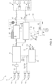
- For a better understanding of the present invention, a preferred embodiment is described in the following, by way of a non-limiting example, with reference to the attached drawings wherein:
-
Figure 1 is a hydraulic scheme of a hydraulic arrangement according to a first embodiment of the present invention; -
Figure 2 is a hydraulic scheme of a hydraulic arrangement according to a second embodiment of the present invention; -
Figure 3 is a hydraulic scheme of a hydraulic arrangement according to a third embodiment of the present invention; and -
Figure 4 is a hydraulic scheme of a hydraulic arrangement according to a fourth embodiment of the present invention. - Each of
figures 1 to 4 illustrates ahydraulic arrangement 1 for a tractor-trailer system according to a respective embodiment of the present invention. - The tractor-trailer system comprises a tractor and a trailer.
- The tractor comprises
tractor brakes 11, atractor brake valve 12 of thetractor brakes 11, and asecondary brake lever 13. - Conveniently, the
tractor brakes 11 are service brakes. - In particular, the
tractor brakes 11 comprise a rearleft brake 11a, a rearright brake 11b, a frontleft brake 11c and a frontright brake 11d. - Preferably, the
secondary brake lever 13 is a dedicated lever configured to stop the tractor-trailer system when actuated. For example, thesecondary brake lever 13 is a parking lever, e.g. a hand brake, and/or an emergency lever. - Conveniently, the
hydraulic arrangement 1 comprisesbrake pedals 21 configured to actuate thetractor brakes 11. - In particular, the
brake pedals 21 comprise a left brake pedal 21a and aright brake pedal 21b fluidically connected to, respectively, the rearleft brake 11a and the rearright brake 11b via ahydraulic brake valve 22. - Preferably, the
hydraulic brake valve 22 is configured to selectively provide pressure to the rear brakes, i.e. the rearleft brake 11a and the rearright brake 11b, e.g. on the basis of an actuation of thebrake pedals 21, i.e. the left brake pedal 21a and theright brake pedal 21b. - Conveniently, the
tractor brake valve 12 is fluidically downstream of thehydraulic brake valve 22 and fluidically connected thereto via a rear-left-brake conduit 23a and a rear-right-brake conduit 23b. The rear-left-brake conduit 23a is fluidically connected to the rearleft brake 11a, via aconduit 24a, and the rear-right-brake conduit 23b is fluidically connected to the rearright brake 11b, via aconduit 24b. - Preferably, the
tractor brake valve 12 is fluidically interposed between thehydraulic brake valve 22 and the front brakes, i.e. the frontleft brake 11c and the frontright brake 11d. - Conveniently, the front brakes, i.e. the front
left brake 11c and the frontright brake 11d, are fluidically downstream of thetractor brake valve 12 and fluidically connected thereto via a front-brake conduit 25. - Optionally, an electro-actuated
valve 26 is fluidically interposed between thetractor brake valve 12 and the front brakes, i.e. the frontleft brake 11c and the frontright brake 11d. - Preferably, the
tractor brake valve 12 is configured to selectively provide pressure to the front brakes, i.e. the frontleft brake 11c and the frontright brake 11d, e.g. on the basis of the tractor speed and/or the trailer speed. - The trailer comprises
trailer brakes 31 configured to brake the trailer. - In particular, the trailer comprises
first trailer brakes 31a andsecond trailer brakes 31b. - The
hydraulic arrangement 1 comprises: - a
trailer brake valve 41 fluidically interposed between thetractor brake valve 12 and a control line 41' of thetrailer brakes 31, in particular of thefirst trailer brakes 31a; - a
safety valve 42 fluidically interposed between thetractor brake valve 12 and a supplementary line 42' of thetrailer brakes 31, in particular of thesecond trailer brakes 31b; - sensor means 43 configured to generate at least one output indicative of a physical quantity dependent on an actuation of at least one of the
secondary brake lever 13 and thetractor brakes 11; and - a
proportional valve 44 configured to proportionally actuate thetrailer brake valve 41 on the basis of acontrol signal 45 dependent on the at least one output of the sensor means 43. - Conveniently, the
trailer brake valve 41 is configured to selectively provide pressure to the control line 41' so as to actuate thefirst trailer brakes 31a. - In particular, the
trailer brake valve 41 is fluidically downstream of thetractor brake valve 12 and fluidically connected thereto via aconduit 51. Thefirst trailer brakes 31a are fluidically downstream of thetrailer brake valve 41 and fluidically connected thereto via the control line 41'. - Conveniently, the
safety valve 42 is configured to selectively provide pressure to the supplementary line 42' so as to actuate thesecond trailer brakes 31b. - In particular, the
safety valve 42 is fluidically downstream of thetractor brake valve 12 and fluidically connected thereto via aconduit 52 branching off from theconduit 51. Thesecond trailer brakes 31b are fluidically downstream of thesafety valve 42 and fluidically connected thereto via the supplementary line 42'. - Conveniently, the
safety valve 42 is fluidically connected to thetrailer brake valve 41 via aconduit 53 branching off from the control line 41'. - Preferably, the
hydraulic arrangement 1 comprises aswitch 54 interposed between thesafety valve 42 and thetrailer brakes 31, in particular thesecond trailer brakes 31b. - Conveniently, the at least one output of the sensor means 43 depends on the actuation of the
secondary brake lever 13 and/or thetractor brakes 11, as described in detail hereinafter. The actuation of thesecondary brake lever 13 and/or thetractor brakes 11 may be automatic, as is the case in autonomous driving. - Conveniently, the
proportional valve 44 is fluidically upstream of thetrailer brake valve 41 and is external thereto or integrated therein. - According to non-illustrated embodiments, the
proportional valve 44 is hydraulically actuated, i.e. thecontrol signal 45 is a hydraulic signal, and/or pneumatically actuated, i.e. thecontrol signal 45 is a pneumatic signal. - According to the illustrated embodiments, the
proportional valve 44 is an electro-actuated valve, and thehydraulic arrangement 1 comprises anelectronic control unit 61 configured to provide thecontrol signal 45 to the electro-actuatedvalve 44 so as to control an output pressure of thetrailer brake valve 41. - In particular, the
control signal 45 is an electrical signal provided by theelectronic control unit 61 to the electro-actuatedvalve 44. Thecontrol signal 45 is configured to actuate the electro-actuatedvalve 44 so as to control the pressure of the control line 41' of thetrailer brakes 31, in particular of thefirst trailer brakes 31a. - Conveniently, the
electronic control unit 61 is configured to receive asignal 62 indicative of the rotational speed of the engine of the tractor. Conveniently, thesignal 62 is an electrical signal. - Conveniently, the
electronic control unit 61 is configured to receive asignal 63 from thesecondary brake lever 13. Thesignal 63 is indicative of an actuation of thesecondary brake lever 13. Conveniently, thesignal 63 is an electrical signal. - Conveniently, the
electronic control unit 61 is configured to receive asignal 64 from theswitch 54. Thesignal 64 is indicative of a status of the supplementary line 42'. Conveniently, thesignal 64 is an electrical signal. - Conveniently, the
electronic control unit 61 is configured to provide asignal 65 to thesafety valve 42. Thesignal 65 is configured to actuate thesafety valve 42. Conveniently, thesignal 65 is an electrical signal. - Preferably, the sensor means 43 comprise a proportional sensor 71 configured to generate an output indicative of an amount of actuation of the
secondary brake lever 13. - In particular, the output of the proportional sensor 71 is indicative of a percentage, i.e. 0% to 100%, of actuation of the
secondary brake lever 13. - Conveniently, the output of the proportional sensor 71 is the
signal 63, which is received by theelectronic control unit 61. - Preferably, the proportional sensor 71 is a potentiometer.
- According to a first embodiment (
figure 1 ), the sensor means 43 do not comprise pressure sensors configured to generate respective outputs indicative of the respective output pressure of thetrailer brake valve 41 or thetractor brake valve 12. In other words, there are no pressure sensors either fluidically upstream or downstream of thetrailer brake valve 41. - In particular, there is neither a pressure sensor configured to detect the output pressure of the
trailer brake valve 41, i.e. the pressure of the control line 41' and theconduit 53, nor a pressure sensor configured to detect the output pressure of thetractor brake valve 12, i.e. the pressure of theconduit 51 and theconduit 52. - According to the first embodiment, the
electronic control unit 61 is configured to receive the output of the proportional sensor 71, indicative of an amount of actuation of thesecondary brake lever 13, and to control the output pressure of thetrailer brake valve 41, via open-loop control, on the basis of the output of the proportional sensor 71. - In particular, the output pressure of the
tractor brake valve 12 is unknown, because it is not detected by a dedicated pressure sensor, and the output pressure of thetrailer brake valve 41 is unknown, because it is not detected by a dedicated pressure sensor. Theelectronic control unit 61 is configured to implement open-loop control because the quantity to be controlled, i.e. the output pressure of thetrailer brake valve 41, is not known due to lack of a dedicated sensor. However, the output pressure of thetrailer brake valve 41 can be estimated by maps. Therefore, proportional control can be performed via mapped control. - According to a second embodiment (
figure 2 ), the sensor means 43 comprise a first pressure sensor 81 configured to generate an output indicative of the output pressure of thetrailer brake valve 41. - In particular, the first pressure sensor 81 is configured to detect the output pressure of the
trailer brake valve 41, i.e. the pressure of the control line 41' and theconduit 53. - Conveniently, the output of the first pressure sensor 81 is a
signal 82, which is received by theelectronic control unit 61. - According to the second embodiment, the
electronic control unit 61 is configured to receive the output of the first pressure sensor 81 and to control the output pressure of thetrailer brake valve 41, via closed-loop control, on the basis of the output of the first pressure sensor 81. - In particular, the output pressure of the
tractor brake valve 12 is unknown, because it is not detected by a dedicated pressure sensor, and the output pressure of thetrailer brake valve 41 is known, because it is detected by the first pressure sensor 81. Theelectronic control unit 61 is configured to implement closed-loop control because the quantity to be controlled, i.e. the output pressure of thetrailer brake valve 41, is known due to the first pressure sensor 81. Therefore, proportional control can be performed via closed-loop control. - According to the second embodiment, the
tractor brake valve 12 and the electro-actuatedvalve 44 are fluidically connected in series. - In particular, the
trailer brake valve 41 has a series architecture. According to the hydraulic series law, thetrailer brake valve 41 is hydraulically actuated by mainly the greater of the output pressure of thetractor brake valve 12 and an output pressure of the electro-actuatedvalve 44. If the output pressure of thetractor brake valve 12 is greater than the output pressure of the electro-actuatedvalve 44, thetrailer brake valve 41 is hydraulically actuated by the output pressure of thetractor brake valve 12, otherwise thetrailer brake valve 41 is hydraulically actuated by the output pressure of the electro-actuatedvalve 44. - According to a third embodiment (
figure 3 ), the sensor means 43 comprise a second pressure sensor 91 configured to generate an output indicative of an output pressure of thetractor brake valve 12. - In particular, the second pressure sensor 91 is configured to detect the output pressure of the
tractor brake valve 12, i.e. the pressure of theconduit 51 and theconduit 52. - Conveniently, the output of the second pressure sensor 91 is a
signal 92, which is received by theelectronic control unit 61. - According to the third embodiment, the
electronic control unit 61 is configured to receive the output of the second pressure sensor 91 and to control the output pressure of thetrailer brake valve 41, via open-loop control, on the basis of the output of the second pressure sensor 91. - In particular, the output pressure of the
tractor brake valve 12 is known, because it is detected by the second pressure sensor 91, and the output pressure of thetrailer brake valve 41 is unknown, because it is not detected by a dedicated pressure sensor. Theelectronic control unit 61 is configured to implement open-loop control because the quantity to be controlled, i.e. the output pressure of thetrailer brake valve 41, is not known due to lack of a dedicated sensor. However, the output pressure of thetrailer brake valve 41 can be estimated by maps or computation. Therefore, proportional control can be performed via mapped or computed control. - According to a first configuration of the third embodiment, the
tractor brake valve 12 and the electro-actuatedvalve 44 are fluidically connected in series. - In particular, the
trailer brake valve 41 has a series architecture. According to the hydraulic series law, thetrailer brake valve 41 is hydraulically actuated by mainly the greater of the output pressure of thetractor brake valve 12 and an output pressure of the electro-actuatedvalve 44. If the output pressure of thetractor brake valve 12 is greater than the output pressure of the electro-actuatedvalve 44, thetrailer brake valve 41 is hydraulically actuated by the output pressure of thetractor brake valve 12, otherwise thetrailer brake valve 41 is hydraulically actuated by the output pressure of the electro-actuatedvalve 44. - According to a second configuration of the third embodiment, the
tractor brake valve 12 and the electro-actuatedvalve 44 are fluidically connected in parallel. - In particular, the
trailer brake valve 41 has a parallel architecture. According to the hydraulic parallel law, thetrailer brake valve 41 is hydraulically actuated by the sum of the output pressure of thetractor brake valve 12 and an output pressure of the electro-actuatedvalve 44. - According to a fourth embodiment (
figure 4 ), the sensor means 43 comprise a first pressure sensor 81 configured to generate an output indicative of the output pressure of thetrailer brake valve 41 and a second pressure sensor 91 configured to generate an output indicative of an output pressure of thetractor brake valve 12. - In particular, the first pressure sensor 81 of the fourth embodiment is the same as the first pressure sensor 81 of the second embodiment, and the second pressure sensor 91 of the fourth embodiment is the same as the second pressure sensor 91 of the third embodiment. In other words, the fourth embodiment is the combination of the second embodiment and the third embodiment.
- According to the fourth embodiment, the
electronic control unit 61 is configured to receive the output of the first pressure sensor 81 and the output of the second pressure sensor 91, and to control the output pressure of thetrailer brake valve 41, via closed-loop control, on the basis of the output of the first pressure sensor 81 and the output of the second pressure sensor 91. - In particular, the output pressure of the
tractor brake valve 12 is known, because it is detected by the second pressure sensor 91, and the output pressure of thetrailer brake valve 41 is known, because it is detected by the first pressure sensor 81. Theelectronic control unit 61 is configured to implement closed-loop control because the quantity to be controlled, i.e. the output pressure of thetrailer brake valve 41, is known due to the first pressure sensor 81. Therefore, proportional control can be performed via closed-loop control. Furthermore, since the output pressure of thetractor brake valve 12 is also known, a fine control is achievable. - According to a first configuration of the fourth embodiment, the
tractor brake valve 12 and the electro-actuatedvalve 44 are fluidically connected in series. - In particular, the
trailer brake valve 41 has a series architecture. According to the hydraulic series law, thetrailer brake valve 41 is hydraulically actuated by mainly the greater of the output pressure of thetractor brake valve 12 and an output pressure of the electro-actuatedvalve 44. If the output pressure of thetractor brake valve 12 is greater than the output pressure of the electro-actuatedvalve 44, thetrailer brake valve 41 is hydraulically actuated by the output pressure of thetractor brake valve 12, otherwise thetrailer brake valve 41 is hydraulically actuated by the output pressure of the electro-actuatedvalve 44. - According to a second configuration of the fourth embodiment, the
tractor brake valve 12 and the electro-actuatedvalve 44 are fluidically connected in parallel. - In particular, the
trailer brake valve 41 has a parallel architecture. According to the hydraulic parallel law, thetrailer brake valve 41 is hydraulically actuated by the sum of the output pressure of thetractor brake valve 12 and an output pressure of the electro-actuatedvalve 44. - The invention further relates to a tractor-trailer system comprising:
- a tractor comprising
tractor brakes 11, atractor brake valve 12 of thetractor brakes 11, and asecondary brake lever 13; - a trailer comprising
trailer brakes 31; and - the described
hydraulic arrangement 1. - The invention further relates to a method for controlling the described
hydraulic arrangement 1. - The method comprises the steps of:
- generating, by the sensor means 43, the at least one output indicative of a physical quantity dependent on an actuation of at least one of the
secondary brake lever 13 and thetractor brakes 11; - generating the
control signal 45 dependent on the at least one output of the sensor means 43; and - proportionally actuating the
trailer brake valve 41, by theproportional valve 44, on the basis of thecontrol signal 45. - Preferably, the at least one output of the sensor means 43 is received by the
electronic control unit 61, thecontrol signal 45 is generated by theelectronic control unit 61 and provided to theproportional valve 44 so as to proportionally actuate thetrailer brake valve 41. - Conveniently, the at least one output of the sensor means 43 is the output of the proportional sensor 71 indicative of an amount of actuation of the
secondary brake lever 13, i.e. thesignal 63, and/or the output of the first pressure sensor 81 indicative of the output pressure of thetrailer brake valve 41, i.e. thesignal 82, and/or the output of the second pressure sensor 91 indicative of an output pressure of thetractor brake valve 12, i.e. thesignal 92. - In view of the foregoing, the advantages of the
hydraulic arrangement 1 according to the invention are apparent. - The
hydraulic arrangement 1 allows proportional control to be performed thanks to the sensor means 43 and theproportional valve 44 which allows thetrailer brake valve 41 to be proportionally actuated on the basis of thecontrol signal 45 which in turn depends on the at least one output of the sensor means 43. - Both open-loop control and closed-loop control can be implemented, depending on the sensor means 43. Open-loop control allows cost and installation impact to be reduced, while closed-loop control allows to achieve a fine and robust control, i.e. able to compensate for component tolerances.
- The
proportional valve 44 can be easily integrated in current hydraulic arrangements without impacting their current features. - The
hydraulic arrangement 1 allows the trailer to be braked during autonomous driving. - It is clear that modifications can be made to the described
hydraulic arrangement 1 which do not extend beyond the scope of protection defined by the claims. - For example, the first pressure sensor 81 may be replaced by a sensor on the
first trailer brakes 31a, e.g. a linear sensor or a force sensor, whose output is then converted to a pressure, e.g. via maps, and/or the second pressure sensor 91 may be replaced by a sensor on thebrake pedals 21, e.g. an angular sensor or a linear sensor, whose output is then converted to a pressure, e.g. via maps.
Claims (15)
- Hydraulic arrangement for a tractor-trailer system comprising a tractor and a trailer,the tractor comprising tractor brakes (11), a tractor brake valve (12) of the tractor brakes (11), and a secondary brake lever (13),the trailer comprising trailer brakes (31),the hydraulic arrangement (1) comprising:- a trailer brake valve (41) fluidically interposed between the tractor brake valve (12) and a control line (41') of the trailer brakes (31);- a safety valve (42) fluidically interposed between the tractor brake valve (12) and a supplementary line (42') of the trailer brakes (31);- sensor means (43) configured to generate at least one output indicative of a physical quantity dependent on an actuation of at least one of the secondary brake lever (13) and the tractor brakes (11); and- a proportional valve (44) configured to proportionally actuate the trailer brake valve (41) on the basis of a control signal (45) dependent on the at least one output of the sensor means (43).
- Hydraulic arrangement as claimed in claim 1, wherein the proportional valve (44) is an electro-actuated valve, the hydraulic arrangement (1) comprising an electronic control unit (61) configured to provide the control signal (45) to the electro-actuated valve (44) so as to control an output pressure of the trailer brake valve (41).
- Hydraulic arrangement as claimed in claim 2, wherein the sensor means (43) comprise a proportional sensor (71) configured to generate an output indicative of an amount of actuation of the secondary brake lever (13).
- Hydraulic arrangement as claimed in claim 2 or 3, wherein the sensor means (43) comprise a first pressure sensor (81) configured to generate an output indicative of the output pressure of the trailer brake valve (41).
- Hydraulic arrangement as claimed in claim 4, wherein the tractor brake valve (12) and the electro-actuated valve (44) are fluidically connected in series, wherein the electronic control unit (61) is configured to receive the output of the first pressure sensor (81) and to control the output pressure of the trailer brake valve (41), via closed-loop control, on the basis of the output of the first pressure sensor (81).
- Hydraulic arrangement as claimed in claim 2 or 3, wherein the sensor means (43) comprise a second pressure sensor (91) configured to generate an output indicative of an output pressure of the tractor brake valve (12).
- Hydraulic arrangement as claimed in claim 6, wherein the electronic control unit (61) is configured to receive the output of the second pressure sensor (91) and to control the output pressure of the trailer brake valve (41), via open-loop control, on the basis of the output of the second pressure sensor (91).
- Hydraulic arrangement as claimed in claim 7, wherein the tractor brake valve (12) and the electro-actuated valve (44) are fluidically connected in series.
- Hydraulic arrangement as claimed in claim 7, wherein the tractor brake valve (12) and the electro-actuated valve (44) are fluidically connected in parallel.
- Hydraulic arrangement as claimed in claim 2 or 3, wherein the sensor means (43) comprise a first pressure sensor (81) configured to generate an output indicative of the output pressure of the trailer brake valve (41) and a second pressure sensor (91) configured to generate an output indicative of an output pressure of the tractor brake valve (12).
- Hydraulic arrangement as claimed in claim 10, wherein the electronic control unit (61) is configured to receive the output of the first pressure sensor (81) and the output of the second pressure sensor (91), and to control the output pressure of the trailer brake valve (41), via closed-loop control, on the basis of the output of the first pressure sensor (81) and the output of the second pressure sensor (91).
- Hydraulic arrangement as claimed in claim 11, wherein the tractor brake valve (12) and the electro-actuated valve (44) are fluidically connected in series.
- Hydraulic arrangement as claimed in claim 11, wherein the tractor brake valve (12) and the electro-actuated valve (44) are fluidically connected in parallel.
- Tractor-trailer system comprising:- a tractor comprising tractor brakes (11), a tractor brake valve (12) of the tractor brakes (11), and a secondary brake lever (13);- a trailer comprising trailer brakes (31); and- a hydraulic arrangement (1) as claimed in any of the preceding claims.
- Method for controlling a hydraulic arrangement as claimed in any of claims 1 to 13, comprising the steps of:- generating, by the sensor means (43), the at least one output indicative of a physical quantity dependent on an actuation of at least one of the secondary brake lever (13) and the tractor brakes (11);- generating the control signal (45) dependent on the at least one output of the sensor means (43); and- proportionally actuating the trailer brake valve (41), by the proportional valve (44), on the basis of the control signal (45).
Applications Claiming Priority (1)
| Application Number | Priority Date | Filing Date | Title |
|---|---|---|---|
| IT102023000020496A IT202300020496A1 (en) | 2023-10-04 | 2023-10-04 | IMPROVED HYDRAULIC ARRANGEMENT FOR A TRACTOR-TRAILER SYSTEM |
Publications (1)
| Publication Number | Publication Date |
|---|---|
| EP4534367A1 true EP4534367A1 (en) | 2025-04-09 |
Family
ID=89158118
Family Applications (1)
| Application Number | Title | Priority Date | Filing Date |
|---|---|---|---|
| EP24204620.9A Pending EP4534367A1 (en) | 2023-10-04 | 2024-10-04 | Improved hydraulic arrangement for a tractor-trailer system |
Country Status (2)
| Country | Link |
|---|---|
| EP (1) | EP4534367A1 (en) |
| IT (1) | IT202300020496A1 (en) |
Citations (4)
| Publication number | Priority date | Publication date | Assignee | Title |
|---|---|---|---|---|
| DE102009050793A1 (en) * | 2009-10-27 | 2011-04-28 | Robert Bosch Gmbh | Adaptive braking system for load trailers |
| WO2020200347A1 (en) * | 2019-04-05 | 2020-10-08 | Suffel Fördertechnik GmbH & Co. KG | Device and method for braking a trailer vehicle |
| WO2022023048A1 (en) * | 2020-07-29 | 2022-02-03 | Cnh Industrial Italia S.P.A. | Improved hydraulic brake arrangement for off-road vehicle |
| WO2022130077A1 (en) * | 2020-12-15 | 2022-06-23 | Agco International Gmbh | Trailer brake control system |
-
2023
- 2023-10-04 IT IT102023000020496A patent/IT202300020496A1/en unknown
-
2024
- 2024-10-04 EP EP24204620.9A patent/EP4534367A1/en active Pending
Patent Citations (4)
| Publication number | Priority date | Publication date | Assignee | Title |
|---|---|---|---|---|
| DE102009050793A1 (en) * | 2009-10-27 | 2011-04-28 | Robert Bosch Gmbh | Adaptive braking system for load trailers |
| WO2020200347A1 (en) * | 2019-04-05 | 2020-10-08 | Suffel Fördertechnik GmbH & Co. KG | Device and method for braking a trailer vehicle |
| WO2022023048A1 (en) * | 2020-07-29 | 2022-02-03 | Cnh Industrial Italia S.P.A. | Improved hydraulic brake arrangement for off-road vehicle |
| WO2022130077A1 (en) * | 2020-12-15 | 2022-06-23 | Agco International Gmbh | Trailer brake control system |
Also Published As
| Publication number | Publication date |
|---|---|
| IT202300020496A1 (en) | 2025-04-04 |
Similar Documents
| Publication | Publication Date | Title |
|---|---|---|
| US6409285B1 (en) | Front wheel and rear wheel interlocking brake system for motorcycle | |
| CA2935989C (en) | Method for controlling a brake device in a traction vehicle-trailer combination and brake device controlled according to said method | |
| US11634110B2 (en) | Method for adjusting brake pressures of a vehicle, and brake system for carrying out the method | |
| US7317980B2 (en) | Automatic brake device for controlling movement of vehicle in direction opposite to intended direction of movement of driver | |
| EP2093112B1 (en) | Electronically controlled brake apparatus for tractors | |
| US8140236B2 (en) | Method for regulating the brake pressure in motorcycles | |
| US20130238209A1 (en) | Pressure-medium-activated brake device of a vehicle having control routines implemented in a brake controller unit, of a hill start assistant function or creep suppression function | |
| US12594919B2 (en) | Trailer brake control system | |
| US11299134B2 (en) | Electropneumatic brake system having a test mode for the pneumatic backup brake circuit | |
| US20100100278A1 (en) | Brake hold control device | |
| US20190152458A1 (en) | Braking force control apparatus for vehicle | |
| SE509972C2 (en) | Brake pressure regulator for optimizing brake lining wear in a motor vehicle | |
| US6592190B2 (en) | Secondary brake system with electrohydraulic proportional valve | |
| US20230166702A1 (en) | Method for decelerating a vehicle combination | |
| MXPA05013614A (en) | Braking device for motorcycle. | |
| GB2500221A (en) | Vehicle brake apparatus having a trailer with an electro-pneumatic valve, controlled based on a vehicle parameter signal | |
| SE463554B (en) | SEAT AND DEVICE AT VEHICLE BRAKES | |
| CN117794797A (en) | Method for operating a vehicle combination | |
| US12325403B2 (en) | Brake system for commercial vehicle | |
| CN101229809A (en) | motorcycle brakes | |
| US11279332B2 (en) | Braking force control apparatus for vehicle | |
| US6932440B1 (en) | Automotive braking method and devices for carrying out said method | |
| SE516430C2 (en) | Device and method for activating an emergency brake function of a vehicle | |
| JPH10129434A (en) | Slope start control device for tractor / trailer | |
| EP0263668B1 (en) | Fluid pressure operable vehicle braking system |
Legal Events
| Date | Code | Title | Description |
|---|---|---|---|
| PUAI | Public reference made under article 153(3) epc to a published international application that has entered the european phase |
Free format text: ORIGINAL CODE: 0009012 |
|
| STAA | Information on the status of an ep patent application or granted ep patent |
Free format text: STATUS: THE APPLICATION HAS BEEN PUBLISHED |
|
| AK | Designated contracting states |
Kind code of ref document: A1 Designated state(s): AL AT BE BG CH CY CZ DE DK EE ES FI FR GB GR HR HU IE IS IT LI LT LU LV MC ME MK MT NL NO PL PT RO RS SE SI SK SM TR |
|
| STAA | Information on the status of an ep patent application or granted ep patent |
Free format text: STATUS: REQUEST FOR EXAMINATION WAS MADE |
|
| 17P | Request for examination filed |
Effective date: 20251009 |
|
| GRAP | Despatch of communication of intention to grant a patent |
Free format text: ORIGINAL CODE: EPIDOSNIGR1 |
|
| STAA | Information on the status of an ep patent application or granted ep patent |
Free format text: STATUS: GRANT OF PATENT IS INTENDED |
|
| INTG | Intention to grant announced |
Effective date: 20260605 |