EP4534361A1 - Vehicle airbag device - Google Patents
Vehicle airbag device Download PDFInfo
- Publication number
- EP4534361A1 EP4534361A1 EP23827332.0A EP23827332A EP4534361A1 EP 4534361 A1 EP4534361 A1 EP 4534361A1 EP 23827332 A EP23827332 A EP 23827332A EP 4534361 A1 EP4534361 A1 EP 4534361A1
- Authority
- EP
- European Patent Office
- Prior art keywords
- occupant
- inflated
- deployed
- chamber
- airbag
- Prior art date
- Legal status (The legal status is an assumption and is not a legal conclusion. Google has not performed a legal analysis and makes no representation as to the accuracy of the status listed.)
- Pending
Links
Images



Classifications
-
- B—PERFORMING OPERATIONS; TRANSPORTING
- B60—VEHICLES IN GENERAL
- B60R—VEHICLES, VEHICLE FITTINGS, OR VEHICLE PARTS, NOT OTHERWISE PROVIDED FOR
- B60R21/00—Arrangements or fittings on vehicles for protecting or preventing injuries to occupants or pedestrians in case of accidents or other traffic risks
- B60R21/02—Occupant safety arrangements or fittings, e.g. crash pads
- B60R21/16—Inflatable occupant restraints or confinements designed to inflate upon impact or impending impact, e.g. air bags
- B60R21/20—Arrangements for storing inflatable members in their non-use or deflated condition; Arrangement or mounting of air bag modules or components
- B60R21/207—Arrangements for storing inflatable members in their non-use or deflated condition; Arrangement or mounting of air bag modules or components in vehicle seats
-
- B—PERFORMING OPERATIONS; TRANSPORTING
- B60—VEHICLES IN GENERAL
- B60R—VEHICLES, VEHICLE FITTINGS, OR VEHICLE PARTS, NOT OTHERWISE PROVIDED FOR
- B60R21/00—Arrangements or fittings on vehicles for protecting or preventing injuries to occupants or pedestrians in case of accidents or other traffic risks
- B60R21/01—Electrical circuits for triggering passive safety arrangements, e.g. airbags, safety belt tighteners, in case of vehicle accidents or impending vehicle accidents
- B60R21/013—Electrical circuits for triggering passive safety arrangements, e.g. airbags, safety belt tighteners, in case of vehicle accidents or impending vehicle accidents including means for detecting collisions, impending collisions or roll-over
- B60R21/0136—Electrical circuits for triggering passive safety arrangements, e.g. airbags, safety belt tighteners, in case of vehicle accidents or impending vehicle accidents including means for detecting collisions, impending collisions or roll-over responsive to actual contact with an obstacle, e.g. to vehicle deformation, bumper displacement or bumper velocity relative to the vehicle
-
- B—PERFORMING OPERATIONS; TRANSPORTING
- B60—VEHICLES IN GENERAL
- B60R—VEHICLES, VEHICLE FITTINGS, OR VEHICLE PARTS, NOT OTHERWISE PROVIDED FOR
- B60R21/00—Arrangements or fittings on vehicles for protecting or preventing injuries to occupants or pedestrians in case of accidents or other traffic risks
- B60R21/02—Occupant safety arrangements or fittings, e.g. crash pads
- B60R21/16—Inflatable occupant restraints or confinements designed to inflate upon impact or impending impact, e.g. air bags
- B60R21/23—Inflatable members
- B60R21/231—Inflatable members characterised by their shape, construction or spatial configuration
- B60R21/233—Inflatable members characterised by their shape, construction or spatial configuration comprising a plurality of individual compartments; comprising two or more bag-like members, one within the other
-
- B—PERFORMING OPERATIONS; TRANSPORTING
- B60—VEHICLES IN GENERAL
- B60R—VEHICLES, VEHICLE FITTINGS, OR VEHICLE PARTS, NOT OTHERWISE PROVIDED FOR
- B60R21/00—Arrangements or fittings on vehicles for protecting or preventing injuries to occupants or pedestrians in case of accidents or other traffic risks
- B60R2021/003—Arrangements or fittings on vehicles for protecting or preventing injuries to occupants or pedestrians in case of accidents or other traffic risks characterised by occupant or pedestian
- B60R2021/0039—Body parts of the occupant or pedestrian affected by the accident
- B60R2021/0048—Head
-
- B—PERFORMING OPERATIONS; TRANSPORTING
- B60—VEHICLES IN GENERAL
- B60R—VEHICLES, VEHICLE FITTINGS, OR VEHICLE PARTS, NOT OTHERWISE PROVIDED FOR
- B60R21/00—Arrangements or fittings on vehicles for protecting or preventing injuries to occupants or pedestrians in case of accidents or other traffic risks
- B60R21/02—Occupant safety arrangements or fittings, e.g. crash pads
- B60R21/16—Inflatable occupant restraints or confinements designed to inflate upon impact or impending impact, e.g. air bags
- B60R21/23—Inflatable members
- B60R21/231—Inflatable members characterised by their shape, construction or spatial configuration
- B60R2021/23161—Inflatable members characterised by their shape, construction or spatial configuration specially adapted for protecting at least two passengers, e.g. preventing them from hitting each other
-
- B—PERFORMING OPERATIONS; TRANSPORTING
- B60—VEHICLES IN GENERAL
- B60R—VEHICLES, VEHICLE FITTINGS, OR VEHICLE PARTS, NOT OTHERWISE PROVIDED FOR
- B60R21/00—Arrangements or fittings on vehicles for protecting or preventing injuries to occupants or pedestrians in case of accidents or other traffic risks
- B60R21/02—Occupant safety arrangements or fittings, e.g. crash pads
- B60R21/16—Inflatable occupant restraints or confinements designed to inflate upon impact or impending impact, e.g. air bags
- B60R21/23—Inflatable members
- B60R21/231—Inflatable members characterised by their shape, construction or spatial configuration
- B60R21/233—Inflatable members characterised by their shape, construction or spatial configuration comprising a plurality of individual compartments; comprising two or more bag-like members, one within the other
- B60R2021/23308—Inflatable members characterised by their shape, construction or spatial configuration comprising a plurality of individual compartments; comprising two or more bag-like members, one within the other the individual compartments defining the external shape of the bag
-
- B—PERFORMING OPERATIONS; TRANSPORTING
- B60—VEHICLES IN GENERAL
- B60R—VEHICLES, VEHICLE FITTINGS, OR VEHICLE PARTS, NOT OTHERWISE PROVIDED FOR
- B60R21/00—Arrangements or fittings on vehicles for protecting or preventing injuries to occupants or pedestrians in case of accidents or other traffic risks
- B60R21/02—Occupant safety arrangements or fittings, e.g. crash pads
- B60R21/16—Inflatable occupant restraints or confinements designed to inflate upon impact or impending impact, e.g. air bags
- B60R21/23—Inflatable members
- B60R21/235—Inflatable members characterised by their material
- B60R2021/23533—Inflatable members characterised by their material characterised by the manufacturing process
-
- B—PERFORMING OPERATIONS; TRANSPORTING
- B60—VEHICLES IN GENERAL
- B60R—VEHICLES, VEHICLE FITTINGS, OR VEHICLE PARTS, NOT OTHERWISE PROVIDED FOR
- B60R21/00—Arrangements or fittings on vehicles for protecting or preventing injuries to occupants or pedestrians in case of accidents or other traffic risks
- B60R21/01—Electrical circuits for triggering passive safety arrangements, e.g. airbags, safety belt tighteners, in case of vehicle accidents or impending vehicle accidents
- B60R21/013—Electrical circuits for triggering passive safety arrangements, e.g. airbags, safety belt tighteners, in case of vehicle accidents or impending vehicle accidents including means for detecting collisions, impending collisions or roll-over
- B60R21/0134—Electrical circuits for triggering passive safety arrangements, e.g. airbags, safety belt tighteners, in case of vehicle accidents or impending vehicle accidents including means for detecting collisions, impending collisions or roll-over responsive to imminent contact with an obstacle, e.g. using radar systems
-
- B—PERFORMING OPERATIONS; TRANSPORTING
- B60—VEHICLES IN GENERAL
- B60R—VEHICLES, VEHICLE FITTINGS, OR VEHICLE PARTS, NOT OTHERWISE PROVIDED FOR
- B60R21/00—Arrangements or fittings on vehicles for protecting or preventing injuries to occupants or pedestrians in case of accidents or other traffic risks
- B60R21/02—Occupant safety arrangements or fittings, e.g. crash pads
- B60R21/16—Inflatable occupant restraints or confinements designed to inflate upon impact or impending impact, e.g. air bags
- B60R21/23—Inflatable members
- B60R21/231—Inflatable members characterised by their shape, construction or spatial configuration
- B60R21/2334—Expansion control features
- B60R21/2338—Tethers
Definitions
- the present disclosure relates to an airbag device for a vehicle, and more particularly, to an airbag device for a vehicle which restrains and protects a passenger by being inflated and deployed upon vehicle collision.
- a vehicular airbag device is a safety device that protects a passenger by injecting gas into an airbag according to a signal of an impact detection sensor upon vehicle collision, and rapidly inflating the airbag.
- Such an airbag device is installed in a steering wheel, a dashboard, a seat, a sidewall, etc. provided in a vehicle, and protects an occupant by being inflated toward a front side or a side of the occupant upon vehicle collision.
- a vehicle may be provided with a frontal airbag which is deployed in front of a driver seat and a passenger seat, a curtain airbag and a side airbag, which are both deployed from a side chamber of a passenger to protect the passenger, and a knee airbag for protecting passenger's knees, etc.
- the autonomous vehicle detects a condition of each device provided in the vehicle and a condition around the vehicle, by using a high-tech sensor for recognizing things around the vehicle and a high-performance graphic processing device, and travels while controlling an operation of each device provided in the vehicle according to a result of detecting.
- the high-tech sensor may measure a distance between things like a human being, and may detect a danger and help the vehicle view all areas without a blind zone.
- the graphic processing device may grasp a surrounding environment of the vehicle through several cameras, and may analyze an image thereof and help the vehicle safely travel.
- the autonomous vehicle may have a LiDAR device, a sound wave device, a 3D camera, a radar device, etc. mounted therein.
- all seats including a driver seat can freely rotate and an angle of a backrest can be adjusted to be horizontal by a tilting operation.
- a passenger can adjust the angle of the backrest variously, and may rotate the seat and may have a meeting facing a passenger on a back seat.
- Patent document 1 and patent document 2 presented below disclose a passenger protection system configuration for a vehicle.
- the passenger may have a meeting by swiveling a seat in a horizontal direction while moving to a destination, or may have a rest by reclining a backrest backward.
- a direction and a posture of the passenger can be variously changed.
- a frontal airbag device is deployed toward the front of the occupant to protect the occupant.
- the occupant collides with the frontal airbag, the occupant is rebounded due to the airbag and move backward again, colliding with other parts of the vehicle, such as the seat's backrest or headrest.
- the airbag device for a vehicle may cause injury to the occupant who is rebounded by the airbag.
- An object of the present invention is to solve the problems as described above, and is to provide an airbag device for a vehicle which may safely protect an occupant who is rebounded by a frontal airbag which is inflated and deployed in front of the occupant upon a vehicle collision.
- Another object of the present invention is to provide an airbag device for a vehicle which may compensate for a space between an occupant and a frontal airbag device to safely protect the occupant.
- Another object of the present invention is to provide an airbag device for vehicle which may safely restrain and protect an occupant by inflating and deploying in front of the occupant, along both sides as well as behind of the occupant.
- an airbag device for a vehicle includes: a housing installed in a backrest of a seat; an inflator configured to generate a gas upon ignition by a detection signal of an impact detection sensor in the event of a vehicle collision; and an airbag cushion accommodated in the housing in a rolled or folded state to receive the gas generated from the inflator upon the vehicle collision, thereby being inflated and deployed to surround an upper body and a head of an occupant, wherein the airbag cushion compensates a distance between the occupant and the backrest upon the vehicle collision and is inflated and deployed from the backrest toward a rear surface of the occupant so as to prevent the occupant, who is rebounded by a frontal airbag, from being injured due to collision with the backrest.
- the occupant may be safely protected by compensating for the space between the occupant and the frontal airbag device, reducing the space upon the vehicle collision.
- the top surface and both side surfaces of the occupant's head may be restrained by the upper chamber, which is inflated around the head of the occupant, to safely protect the occupant.
- a direction toward the front of the vehicle from a driver's seat will be referred to as forward,' and a direction toward the rear of the vehicle from the driver's seat will be referred to as 'backward.
- terms indicating directions such as 'left side,' 'right side,' 'upward direction,' and 'downward direction' are defined to indicate respective directions with reference to the forward direction and the backward direction described above.
- FIG. 1 is a perspective view of an airbag device for a vehicle according to a first embodiment of the present invention
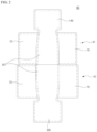
- FIG. 2 is an exploded view of an airbag cushion shown in FIG.1
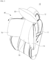
- FIGS. 3 to 5 are a perspective view, a front view, and a side view, respectively, illustrating a state in which the airbag cushion shown in FIG. 1 is inflated and deployed.
- an airbag device 10 for a vehicle is installed in a seat of the vehicle and inflated and deployed toward a rear surface of an occupant who is rebounded after colliding with a frontal airbag.
- the occupant who is rebounded after colliding with the frontal airbag may be protected from injury due to a collision with devices inside the vehicle, such as a backrest 11 of the seat.
- a space between the frontal airbag and the occupant may be compensated to be reduced in a state in which the occupant rotates the backrest backward, effectively restraining and safely protecting the occupant.
- the airbag device 10 for the vehicle includes a housing 20 installed on the backrest 11 of the seat, an inflater 30 that generates a gas upon ignition by a detection signal of an impact detection sensor in the event of a vehicle collision, and an airbag cushion 40 accommodated in the housing 20 in a rolled or folded state to receive the gas generated from the inflator 30 and inflated and deployed to surround an upper body and a head portion of the occupant.
- the housing 20 may have an approximately rectangular prism shape and be accommodated in an upper end of an inner space of the backrest 11.
- a cutting line may be defined in a front surface of the backrest 11 so that the airbag cushion 40 is inflated and deployed toward the occupant.
- the inflater 30 may be accommodated in a rear internal space of the housing 20 to generate the gas upon ignition according to the detection signal of the impact detection sensor installed in the vehicle.
- the airbag cushion 40 may include a main chamber 50 which is inflated and deployed toward rear surfaces of a neck and the upper body of the occupant and an upper chamber 60 which is inflated and deployed toward the rear surface of the head of the occupant, so that the head and the upper body of the occupant is surrounded and protected.
- the airbag cushion 40 may further include a pair of side chambers 70 which are inflated and deployed toward both sides of the upper body of the occupant to prevent the occupant from lateral movement.
- a space in which the upper body including the head, neck and the back of the occupant is entirely accommodated may be defined inside the inflated and deployed airbag cushion 40.
- the airbag cushion 40 may include an inner panel 41, which is in contact with the occupant and an external panel 42, which is in contact with the opposite side of the inner panel 41, specifically, the backrest 11, during inflation and deployment.
- the inner panel 41 and the external panel 42 may be provided as a single interconnected panel and have a bag shape through sewing or bonding along edges while being overlapped with each other, or a one-piece woven method.
- the inner panel 41 and the external panel 42 may have a symmetric shape.
- the external panel 42 may have a longer length in at least one of the horizontal or vertical dimensions than the inner panel 41 so that the external panel 42 surrounds the back of the occupant when the main chamber 50 is inflated and deployed.
- the main chamber 50 may have a vertical length corresponding to the neck and back of the occupant. That is, the main chamber 50 may be inflated and deployed on the neck and back of the occupant to protect them by minimizing the impact applied to the occupant's cervical spine and vertebrae.
- the present invention is not limited thereto, and the main chamber may be modified to extend in length vertically to correspond not only to the neck and back of the occupant but also to the waist as needed.
- the upper chamber 60 may be connected to an upper end of the main chamber 50 to receive the gas through the main chamber 50, being inflated and deployed.
- the upper chamber 60 may be inflated and deployed between the occupant's head and a headrest 12 installed on an upper end of the backrest 11 to absorb impact applied when the occupant's head collides with the headrest 12.
- the external panel 42 may have a longer length in at least one of the horizontal or vertical dimensions than the inner panel 41 so that the external panel 42 surrounds the head of the occupant when the upper chamber 60 is deployed.
- the pair of side chambers 70 may be connected to both sides of the main chamber 50, respectively, to receive the gas through the main chamber 50, being inflated and deployed.
- the external panel 42 may have a horizontal length longer than that of the inner panel 41 so that the external panel 42 surrounds the occupant's shoulder and upper arms when the side chambers 70 are deployed.
- the main chamber 50 and the pair of side chambers 70 may be concavely inflated and deployed in an approximately semicircular or arc shape when viewed from above so that a rear surface and side surfaces of the upper body of the occupant are entirely surrounded.
- a plurality of tethers (not shown), which limits a deployment shape of each of the chambers 50 to 70 provided in the airbag cushion 40, may be installed between the inner panel 41 and the external panel 42.
- one or more tethers defining a deployment shape of the upper chamber 60 may be installed inside or outside the upper chamber 60 so that the upper chamber 60 is inflated and deployed while rotated forward with respect to a lower end thereof.
- both ends of the tether may be connected to the main chamber 50 and an upper end of the upper chamber 60.
- each side chamber 70 may be installed inside or outside the pair of side chambers 70 so that each side chamber 70 is inflated and deployed while rotated toward the occupant with respect to a portion on which the side chamber 70 is connected to the main chamber 50.
- Both ends of the tether may be connected to the main chamber 50 and an outer end of the side chamber 70.
- the present invention is not limited thereto, and the number of tethers, positions where the tethers are installed, lengths, widths, and other parameters can be varied.
- the present invention may provide different horizontal and vertical lengths for the inner and outer panels and, besides applying tethers, may also change the configuration by forming various patterns of seams along the edges and inside of each chamber to limit the deployment shape of each chamber.
- the occupant may be safely protected by compensating for the space between the occupant and the frontal airbag device, reducing the space upon the vehicle collision.
- the impact which occurs when the occupant is rebounded by the frontal airbag inflated and deployed in front of the occupant and collides with the seat, may be effectively absorbed to safely protect the occupant.
- FIG. 6 is an operational state view illustrating a state in which the airbag device for the vehicle is operated according to a preferred embodiment of the present invention.
- the airbag cushion 40 is manufactured in a bag shape by sewing the edges while the inner panel 41 and the external panel 42 are arranged to overlap each other, based on the deployed state shown in FIG. 2 .
- the airbag cushion 40 is inflated and deployed between the occupant and the backrest 11 and headrest 12, the space between the occupant and the backrest 11 and headrest 12 may be compensated to be reduced, thereby minimizing the impact applied to the rebounding occupant.
- the impact which occurs when the occupant is rebounded by the frontal airbag inflated and deployed in front of the occupant and collides with the seat, may be effectively absorbed to safely protect the occupant.
- an airbag cushion 40 may further include a main chamber 50, which is inflated and deployed toward the occupant's neck and the rear surface of the upper body, and an upper chamber 60, which is inflated and deployed toward the rear surface of the occupant's head, so that the occupant's head and the upper body is surrounded and protected, and a pair of side chambers 70, which is inflated and deployed from both sides of the main chamber 50 toward both side surfaces of the upper body of the occupant to prevent lateral movement of the occupant.
- the upper chamber 60 may include a rear surface chamber 61 corresponding to the rear surface of the occupant's head, a top surface chamber 62 that surrounds the top surface of the occupant's head, and a pair of side surface chambers 63 that surround both side surfaces of the head.
- the upper chamber 62 may extend from an upper end of the rear surface chamber 61 and inflated and deployed approximately forward.
- the upper chamber 62 may be partitioned into a plurality of chambers by chamber walls to be inflated and deployed along the top surface of the occupant's head.
- the chamber walls may be provided with one or more in parallel along the lateral direction when viewed in FIG. 7 .
- the upper chamber 62 may be inclined upward and forward to inflate from an upper end of the rear surface of the occupant's head toward the occupant's crown, and then inclined downward to inflate from the crown of the head toward the forehead.
- the tether members may connect at both ends to front and rear ends of the upper chamber 62, respectively, ensuring that the cross-section of the upper chamber 62 appears a convex shape when viewed from one side.
- the upper chamber 62 which is inflated and deployed forward, may have a length that varies to surround the top surface and forehead of the occupant's head, or a portion of an upper end of the face.
- each of the side surface chambers 63 may be partitioned into a plurality of chambers by chamber walls to be inflated and deployed along both side surfaces of the occupant's head.
- the chamber walls may be provided with one or more in parallel along the lateral direction when viewed in FIG. 7 .
- the side surface chamber 63 may be inflated while inclined forward and outward from both ends of the rear surface of the occupant's head toward both ears of the occupant during the initial deployment, and then be inflated while inclined forward and inward from both ears of the occupant toward a front of the occupant's face.
- one or more tether members may be provided inside or outside the side surface chamber 63 to limit a deployment shape of the side surface chamber 63.
- the tether members may connect at both ends to front and rear ends of the side surface chamber 63, respectively, ensuring that the cross-section of the side surface chamber 63 appears a convex shape, i.e., '()'shape, when viewed from above.
- the side chamber 62 which is inflated and deployed forward, may have a length that varies to surround both side surfaces of the occupant's head and a portion of both ends of the face.
- the pair of side chambers 70 may be connected to both sides of the main chamber 50, respectively, to receive the gas through the main chamber 50, being inflated and deployed.
- the pair of side chambers 70 may be inflated and deployed respectively on outer sides of occupant's shoulders and upper arms to restrain and protect the occupant's shoulders and upper arms.
- the external panel 42 may have a horizontal length longer than that of the inner panel 41 so that the external panel 42 surrounds the occupant's shoulder and upper arms when the side chambers 70 are deployed.
- the main chamber 50 and the pair of side chambers 70 may be concavely inflated and deployed in an approximately semicircular or arc shape when viewed from above so that a rear surface and side surfaces of the upper body of the occupant are entirely surrounded.
- a plurality of tethers (not shown), which limits a deployment shape of each of the chambers 50 to 70 provided in the airbag cushion 40, may be installed between the inner panel 41 and the external panel 42.
- each side chamber 70 may be installed inside or outside the pair of side chambers 70 so that each side chamber 70 is inflated and deployed while rotated toward the occupant with respect to a portion on which the side chamber 70 is connected to the main chamber 50.
- Both ends of the tether member may be connected to the main chamber 50 and an outer end of the side chamber 70.
- the present invention is not limited thereto, and the number of tethers, positions where the tethers are installed, lengths, widths, can be varied.
- the present invention may provide different horizontal and vertical lengths for the inner and outer panels and, besides applying tethers, may also change the configuration by forming various patterns of seams along the edges and inside of each chamber to define the deployment shape of each chamber.
- the occupant may be safely protected by compensating for the space between the occupant and the frontal airbag device, reducing the space upon a vehicle collision.
- the impact which occurs when the occupant is rebounded by the frontal airbag inflated and deployed in front of the occupant and collides with the seat, may be effectively absorbed to safely protect the occupant.
- the top surface and both side surfaces of the occupant's head may be restrained by the upper chamber, which is inflated around the head of the occupant, to safely protect the occupant.
- FIG. 11 is an operational state view illustrating a state in which the airbag device for the vehicle is operated according to second embodiment of the present invention.
- an airbag cushion 40 is manufactured in a bag shape by sewing the edges while an inner panel 41 and an external panel 42 are arranged to overlap each other, based on the deployed state shown in FIG. 7 .
- the manufactured airbag cushion 40 may be accommodated in a folded state within a housing 20 using various rolling or folding methods to minimize the volume, and may be installed into a backrest 11 of the seat, for example, on an upper frontal side of the backrest 11.
- the airbag cushion 40 may be inflated and deployed outward from a cover of the backrest 11 by receiving the gas from an inflator 30.
- a main chamber 50 may be inflated and deployed in front of the backrest 11, while each of an upper chamber 60 and a pair of side chambers 70 receive gas through the main chamber 50 and is inflated and deployed at the top and both sides of the main chamber 50.
- the upper chamber 60 and the pair of side chambers 70 rotate downward and inward toward the occupant around the main chamber 50, entirely surrounding and restraining the occupant.
- a rear surface chamber 61 of the upper chamber 60 may be inflated and deployed between the occupant's head and a headrest 12 to absorb an impact applied when the occupant's head collides with the headrest 12 due to the collision.
- a top surface chamber 62 and a pair of side surface chambers 63 of the upper chamber 60 may be inflated and deployed forward along a top surface and both side surfaces of the occupant's head, respectively. Therefore, the upper chamber 60 may restrain not only the rear surface of the occupant's head but also the top surface and both side surface of the occupant's head to prevent the occupant's head from laterally moving, thereby effectively protecting occupant from the impact applied from the outside.
- the pair of side chambers 70 may surround and restrain both side surfaces of an upper body of the occupant.
- each of the chambers 50 to 70 provided in the airbag cushion 40 may be inflated and deployed to entirely surround and restrain the occupant's upper body and head, thereby preventing lateral movement of the occupant and ensuring safety.
- a frontal airbag 80 which is inflated and deployed at the front, the occupant may be rebounded backward due to the pressure of the frontal airbag 80.
- the airbag cushion 40 is inflated and deployed between the occupant and the backrest 11 and headrest 12, the space between the occupant and the backrest 11 and headrest 12 may be compensated to be reduced, thereby minimizing the impact applied to the rebounding occupant.
- the airbag cushion when a collision occurs with the occupant in a state where the backrest is rotated backward, the airbag cushion may be used to compensate for the space between the occupant and the backrest, minimizing the impact applied when the occupant collides with the backrest.
- the occupant may be safely protected by compensating for the space between the occupant and the frontal airbag device, reducing the space upon the vehicle collision.
- the impact which occurs when the occupant is rebounded by the frontal airbag inflated and deployed in front of the occupant and collides with the seat, may be effectively absorbed to safely protect the occupant.
- the top surface and both side surfaces of the occupant's head may be restrained by the upper chamber, which is inflated around the head of the occupant, to safely protect the occupant.
- the present invention may be applied to a technology in which the space between the occupant and the frontal airbag device may be compensated to be reduced, thereby safely protecting the occupant upon the vehicle collision.
Landscapes
- Engineering & Computer Science (AREA)
- Mechanical Engineering (AREA)
- Air Bags (AREA)
Abstract
Description
- The present disclosure relates to an airbag device for a vehicle, and more particularly, to an airbag device for a vehicle which restrains and protects a passenger by being inflated and deployed upon vehicle collision.
- A vehicular airbag device is a safety device that protects a passenger by injecting gas into an airbag according to a signal of an impact detection sensor upon vehicle collision, and rapidly inflating the airbag.
- Such an airbag device is installed in a steering wheel, a dashboard, a seat, a sidewall, etc. provided in a vehicle, and protects an occupant by being inflated toward a front side or a side of the occupant upon vehicle collision.
- That is, a vehicle may be provided with a frontal airbag which is deployed in front of a driver seat and a passenger seat, a curtain airbag and a side airbag, which are both deployed from a side chamber of a passenger to protect the passenger, and a knee airbag for protecting passenger's knees, etc.
- Recently, autonomous vehicles that can drive themselves without the need for a driver are being developed.
- The autonomous vehicle detects a condition of each device provided in the vehicle and a condition around the vehicle, by using a high-tech sensor for recognizing things around the vehicle and a high-performance graphic processing device, and travels while controlling an operation of each device provided in the vehicle according to a result of detecting.
- The high-tech sensor may measure a distance between things like a human being, and may detect a danger and help the vehicle view all areas without a blind zone. In addition, the graphic processing device may grasp a surrounding environment of the vehicle through several cameras, and may analyze an image thereof and help the vehicle safely travel.
- For example, the autonomous vehicle may have a LiDAR device, a sound wave device, a 3D camera, a radar device, etc. mounted therein.
- As the autonomous vehicles configured as described above do not require drivers to drive, all seats including a driver seat can freely rotate and an angle of a backrest can be adjusted to be horizontal by a tilting operation.
- A passenger can adjust the angle of the backrest variously, and may rotate the seat and may have a meeting facing a passenger on a back seat.
- Accordingly, it is impossible to apply a normal airbag apparatus which is designed with reference to a posture of a passenger sitting on a seat facing forward to the autonomous vehicles.
- Patent document 1 and patent document 2 presented below disclose a passenger protection system configuration for a vehicle.
- As a passenger riding in an autonomous vehicle does not directly drive, the passenger may have a meeting by swiveling a seat in a horizontal direction while moving to a destination, or may have a rest by reclining a backrest backward.
- As the seat and the backrest can be freely swiveled in the autonomous vehicle, a direction and a posture of the passenger can be variously changed.
- Accordingly, there is a demand for airbag technology for safely protecting a passenger regardless of a direction and a posture of the passenger upon vehicle collision.
- Particularly, in the case of a frontal collision in not only autonomous vehicles but also conventional vehicles where the occupant has rotated the backrest backward, a frontal airbag device is deployed toward the front of the occupant to protect the occupant.
- However, after the occupant collides with the frontal airbag, the occupant is rebounded due to the airbag and move backward again, colliding with other parts of the vehicle, such as the seat's backrest or headrest.
- As a result, the airbag device for a vehicle according to related art may cause injury to the occupant who is rebounded by the airbag.
- Also, when the occupant rotates the backrest backward, as a space between the frontal airbag device and the occupant increases, which may result in the frontal airbag device alone being unable to effectively restrain and protect the occupant.
- Therefore, there is a need for the development of a technology that can safely protect an occupant by compensating for the space between the occupant who is rebounded after colliding with the airbag, especially the occupant who is in a state of having rotated the backrest backward, and the frontal airbag device.
- (Patent Document 1)
Korean Patent Registration No. 10-1655569 (published on September 08, 2016 - (Patent Document 2)
Korean Patent Registration No. 10-1611087 (published on April 11, 2016 - An object of the present invention is to solve the problems as described above, and is to provide an airbag device for a vehicle which may safely protect an occupant who is rebounded by a frontal airbag which is inflated and deployed in front of the occupant upon a vehicle collision.
- Another object of the present invention is to provide an airbag device for a vehicle which may compensate for a space between an occupant and a frontal airbag device to safely protect the occupant.
- Further another object of the present invention is to provide an airbag device for vehicle which may safely restrain and protect an occupant by inflating and deploying in front of the occupant, along both sides as well as behind of the occupant.
- To achieve an object as described above, an airbag device for a vehicle according to the present invention includes: a housing installed in a backrest of a seat; an inflator configured to generate a gas upon ignition by a detection signal of an impact detection sensor in the event of a vehicle collision; and an airbag cushion accommodated in the housing in a rolled or folded state to receive the gas generated from the inflator upon the vehicle collision, thereby being inflated and deployed to surround an upper body and a head of an occupant, wherein the airbag cushion compensates a distance between the occupant and the backrest upon the vehicle collision and is inflated and deployed from the backrest toward a rear surface of the occupant so as to prevent the occupant, who is rebounded by a frontal airbag, from being injured due to collision with the backrest.
- As described above, according to the airbag device for the vehicle in the present invention, the occupant may be safely protected by compensating for the space between the occupant and the frontal airbag device, reducing the space upon the vehicle collision.
- In addition, according to the present invention, the impact, which occurs when the occupant is rebounded by the frontal airbag inflated and deployed in front of the occupant and collides with the seat, may be effectively absorbed to safely protect the occupant.
- Moreover, according to the present invention, the top surface and both side surfaces of the occupant's head may be restrained by the upper chamber, which is inflated around the head of the occupant, to safely protect the occupant.
-
-
FIG. 1 is a perspective view of an airbag device for a vehicle according to a first embodiment of the present invention; -
FIG. 2 is an exploded view of an airbag cushion shown inFIG.1 ; -
FIGS. 3 to 5 are a perspective view, a front view, and a side view, respectively, illustrating a state in which the airbag cushion shown inFIG. 1 is inflated and deployed; -
FIG. 6 is an operational state view illustrating a state in which the airbag device for the vehicle is operated according to a preferred embodiment of the present invention; -
FIG. 7 is an exploded view of an airbag cushion applied to an airbag device for a vehicle according to a second embodiment of the present invention; -
FIGS. 8 to 10 are a perspective view, a front view, and a side view, respectively, illustrating a state in which the airbag cushion shown inFIG. 7 is inflated and deployed; and -
FIG. 11 is an operational state view illustrating a state in which the airbag device for the vehicle is operated according to the second embodiment of the present invention. - Hereinafter, an airbag apparatus for a vehicle according to preferred embodiments of the present disclosure will be described in detail with reference to the accompanying drawings.
- Although the operation is explained using the configuration of an airbag system applied to an autonomous vehicle in autonomous driving mode in this embodiment, it should be noted that the present invention is not limited thereto and can also be applied to manual driving mode when the driver operates the vehicle, as well as in conventional vehicles with existing airbag cushions.
- In this embodiment, the configuration installed in the backrest of the passenger seat of a conventional vehicle is explained, however, it should be noted that the present invention can be applied not only to the driver's seat but also to the rear seats.
- Hereinafter, a direction toward the front of the vehicle from a driver's seat will be referred to as forward,' and a direction toward the rear of the vehicle from the driver's seat will be referred to as 'backward.' Along with these terms, terms indicating directions such as 'left side,' 'right side,' 'upward direction,' and 'downward direction' are defined to indicate respective directions with reference to the forward direction and the backward direction described above.
-
FIG. 1 is a perspective view of an airbag device for a vehicle according to a first embodiment of the present invention,FIG. 2 is an exploded view of an airbag cushion shown inFIG.1 , andFIGS. 3 to 5 are a perspective view, a front view, and a side view, respectively, illustrating a state in which the airbag cushion shown inFIG. 1 is inflated and deployed. - As shown in
FIG. 1 , anairbag device 10 for a vehicle according to the present invention is installed in a seat of the vehicle and inflated and deployed toward a rear surface of an occupant who is rebounded after colliding with a frontal airbag. - Accordingly, according to the present invention, the occupant who is rebounded after colliding with the frontal airbag may be protected from injury due to a collision with devices inside the vehicle, such as a
backrest 11 of the seat. - In addition, according to the present invention, a space between the frontal airbag and the occupant may be compensated to be reduced in a state in which the occupant rotates the backrest backward, effectively restraining and safely protecting the occupant.
- In detail, as shown in
FIG. 1 , theairbag device 10 for the vehicle according to a first embodiment of the present invention includes ahousing 20 installed on thebackrest 11 of the seat, aninflater 30 that generates a gas upon ignition by a detection signal of an impact detection sensor in the event of a vehicle collision, and anairbag cushion 40 accommodated in thehousing 20 in a rolled or folded state to receive the gas generated from theinflator 30 and inflated and deployed to surround an upper body and a head portion of the occupant. - The
housing 20 may have an approximately rectangular prism shape and be accommodated in an upper end of an inner space of thebackrest 11. - A cutting line may be defined in a front surface of the
backrest 11 so that theairbag cushion 40 is inflated and deployed toward the occupant. - The
inflater 30 may be accommodated in a rear internal space of thehousing 20 to generate the gas upon ignition according to the detection signal of the impact detection sensor installed in the vehicle. - As shown in
FIGS. 2 to 5 , theairbag cushion 40 may include amain chamber 50 which is inflated and deployed toward rear surfaces of a neck and the upper body of the occupant and anupper chamber 60 which is inflated and deployed toward the rear surface of the head of the occupant, so that the head and the upper body of the occupant is surrounded and protected. - Also, the
airbag cushion 40 may further include a pair ofside chambers 70 which are inflated and deployed toward both sides of the upper body of the occupant to prevent the occupant from lateral movement. - Accordingly, a space in which the upper body including the head, neck and the back of the occupant is entirely accommodated may be defined inside the inflated and deployed
airbag cushion 40. - The
airbag cushion 40 may include aninner panel 41, which is in contact with the occupant and anexternal panel 42, which is in contact with the opposite side of theinner panel 41, specifically, thebackrest 11, during inflation and deployment. - As shown in
FIG. 2 , theinner panel 41 and theexternal panel 42 may be provided as a single interconnected panel and have a bag shape through sewing or bonding along edges while being overlapped with each other, or a one-piece woven method. - For this purpose, the
inner panel 41 and theexternal panel 42 may have a symmetric shape. - However, in the
main chamber 50 area, theexternal panel 42 may have a longer length in at least one of the horizontal or vertical dimensions than theinner panel 41 so that theexternal panel 42 surrounds the back of the occupant when themain chamber 50 is inflated and deployed. - The
main chamber 50 may have a vertical length corresponding to the neck and back of the occupant. That is, themain chamber 50 may be inflated and deployed on the neck and back of the occupant to protect them by minimizing the impact applied to the occupant's cervical spine and vertebrae. - The present invention is not limited thereto, and the main chamber may be modified to extend in length vertically to correspond not only to the neck and back of the occupant but also to the waist as needed.
- The
upper chamber 60 may be connected to an upper end of themain chamber 50 to receive the gas through themain chamber 50, being inflated and deployed. - That is, the
upper chamber 60 may be inflated and deployed between the occupant's head and aheadrest 12 installed on an upper end of thebackrest 11 to absorb impact applied when the occupant's head collides with theheadrest 12. - In the
upper chamber 60 area, theexternal panel 42 may have a longer length in at least one of the horizontal or vertical dimensions than theinner panel 41 so that theexternal panel 42 surrounds the head of the occupant when theupper chamber 60 is deployed.
the pair ofside chambers 70 may be connected to both sides of themain chamber 50, respectively, to receive the gas through themain chamber 50, being inflated and deployed. - That is, the pair of
side chambers 70 may be inflated and deployed respectively on outer sides of occupant's shoulders and upper arms to restrain and protect the occupant's shoulders and upper arms. - In the pair of
side chambers 70 area, theexternal panel 42 may have a horizontal length longer than that of theinner panel 41 so that theexternal panel 42 surrounds the occupant's shoulder and upper arms when theside chambers 70 are deployed. - Therefore, the
main chamber 50 and the pair ofside chambers 70 may be concavely inflated and deployed in an approximately semicircular or arc shape when viewed from above so that a rear surface and side surfaces of the upper body of the occupant are entirely surrounded. - Also, a plurality of tethers (not shown), which limits a deployment shape of each of the
chambers 50 to 70 provided in theairbag cushion 40, may be installed between theinner panel 41 and theexternal panel 42. - For example, one or more tethers defining a deployment shape of the
upper chamber 60 may be installed inside or outside theupper chamber 60 so that theupper chamber 60 is inflated and deployed while rotated forward with respect to a lower end thereof. - For this purpose, both ends of the tether may be connected to the
main chamber 50 and an upper end of theupper chamber 60. - Also, one or more tethers defining a deployment shape of each
side chamber 70 may be installed inside or outside the pair ofside chambers 70 so that eachside chamber 70 is inflated and deployed while rotated toward the occupant with respect to a portion on which theside chamber 70 is connected to themain chamber 50. - Both ends of the tether may be connected to the
main chamber 50 and an outer end of theside chamber 70. - The present invention is not limited thereto, and the number of tethers, positions where the tethers are installed, lengths, widths, and other parameters can be varied.
- Additionally, the present invention may provide different horizontal and vertical lengths for the inner and outer panels and, besides applying tethers, may also change the configuration by forming various patterns of seams along the edges and inside of each chamber to limit the deployment shape of each chamber.
- As described above, according to the present invention, the occupant may be safely protected by compensating for the space between the occupant and the frontal airbag device, reducing the space upon the vehicle collision.
- In addition, according to the present invention, the impact, which occurs when the occupant is rebounded by the frontal airbag inflated and deployed in front of the occupant and collides with the seat, may be effectively absorbed to safely protect the occupant.
- Next, an operating method of the airbag device of the vehicle according to the first embodiment of the present invention will be described in detail with reference to
FIG. 6 . -
FIG. 6 is an operational state view illustrating a state in which the airbag device for the vehicle is operated according to a preferred embodiment of the present invention. - First, the
airbag cushion 40 is manufactured in a bag shape by sewing the edges while theinner panel 41 and theexternal panel 42 are arranged to overlap each other, based on the deployed state shown inFIG. 2 . - The manufactured
airbag cushion 40 may be accommodated in a folded state within thehousing 20 using various rolling or folding methods to minimize the volume, and may be installed into thebackrest 11 of the seat, for example, on an upper frontal side of thebackrest 11. - In the event of the collision during vehicle operation, the
airbag cushion 40 may be inflated and deployed outward from a cover of thebackrest 11 by receiving the gas from theinflator 30. - That is, the
main chamber 50 may be inflated and deployed in front of thebackrest 11, while each of theupper chamber 60 and the pair ofside chambers 70 receive gas through themain chamber 50 and is inflated and deployed at the top and both sides of themain chamber 50. - Here, the
upper chamber 60 and the pair ofside chambers 70 rotate downward and inward toward the occupant around themain chamber 50, entirely surrounding and restraining the occupant. - In this way, each of the
chambers 50 to 70 provided in theairbag cushion 40 may be inflated and deployed to entirely surround and restrain the occupant's upper body and head, thereby preventing lateral movement of the occupant and ensuring safety. - In the event of a frontal collision, the occupant moves forward in the vehicle. Therefore, after the occupant is firstly protected by a
frontal airbag 80, which is inflated and deployed at the front, the occupant may be rebounded backward due to the pressure of thefrontal airbag 80. - At this time, as the
airbag cushion 40 is inflated and deployed between the occupant and thebackrest 11 andheadrest 12, the space between the occupant and thebackrest 11 andheadrest 12 may be compensated to be reduced, thereby minimizing the impact applied to the rebounding occupant. - In other words, according to the present invention, when the collision occurs with the occupant in a state where the backrest rotates backward, the airbag cushion may be used to compensate for the space between the occupant and the backrest, minimizing the impact applied when the occupant collides with the backrest.
- As described above, according to the present invention, the occupant may be safely protected by compensating for the space between the occupant and the frontal airbag device, reducing the space upon the vehicle collision.
- In addition, according to the present invention, the impact, which occurs when the occupant is rebounded by the frontal airbag inflated and deployed in front of the occupant and collides with the seat, may be effectively absorbed to safely protect the occupant.
-
FIG. 7 is an exploded view of an airbag cushion applied to an airbag device for a vehicle according to a second embodiment of the present invention; -
FIGS. 8 to 10 are a perspective view, a front view, and a side view, respectively, illustrating a state in which the airbag cushion shown inFIG. 7 is inflated and deployed. - An
airbag device 10 for a vehicle according to the present invention is configured identically to the airbag device of the vehicle described with reference toFIG. 1 , except that the shape of theairbag cushion 40 is modified. - More specifically, as shown in
FIGS. 7 to 10 , anairbag cushion 40 may further include amain chamber 50, which is inflated and deployed toward the occupant's neck and the rear surface of the upper body, and anupper chamber 60, which is inflated and deployed toward the rear surface of the occupant's head, so that the occupant's head and the upper body is surrounded and protected, and a pair ofside chambers 70, which is inflated and deployed from both sides of themain chamber 50 toward both side surfaces of the upper body of the occupant to prevent lateral movement of the occupant. - Accordingly, a space in which the upper body including the head, neck and the back of the occupant is entirely accommodated may be defined inside the inflated and deployed
airbag cushion 40. - In this embodiment, the
upper chamber 60 may extend to surround a top surface and both side surfaces of the occupant's head to restrain lateral movement of the occupant's head or to absorb the impact applied when the occupant's head collides with theheadrest 12 while moving backward. - That is, the
upper chamber 60 may include arear surface chamber 61 corresponding to the rear surface of the occupant's head, atop surface chamber 62 that surrounds the top surface of the occupant's head, and a pair ofside surface chambers 63 that surround both side surfaces of the head. - The
rear chamber 61 may have various shapes, such as approximately polygonal, circular, or elliptical in a cross-section, to correspond to the rear surface of the occupant's head. - The
upper chamber 62 may extend from an upper end of therear surface chamber 61 and inflated and deployed approximately forward. - Here, the
upper chamber 62 may be partitioned into a plurality of chambers by chamber walls to be inflated and deployed along the top surface of the occupant's head. For example, the chamber walls may be provided with one or more in parallel along the lateral direction when viewed inFIG. 7 . - Therefore, during an initial deployment, the
upper chamber 62 may be inclined upward and forward to inflate from an upper end of the rear surface of the occupant's head toward the occupant's crown, and then inclined downward to inflate from the crown of the head toward the forehead. - Additionally, one or more tether members (not shown) may be provided inside or outside the
upper chamber 62 to limit a deployment shape of theupper chamber 62. - For instance, the tether members may connect at both ends to front and rear ends of the
upper chamber 62, respectively, ensuring that the cross-section of theupper chamber 62 appears a convex shape when viewed from one side. - The
upper chamber 62, which is inflated and deployed forward, may have a length that varies to surround the top surface and forehead of the occupant's head, or a portion of an upper end of the face. - The pair of
side surface chambers 63 may extend from both ends of therear surface chamber 61, respectively, and be inflated and deployed approximately forward. - Here, each of the
side surface chambers 63 may be partitioned into a plurality of chambers by chamber walls to be inflated and deployed along both side surfaces of the occupant's head. For example, the chamber walls may be provided with one or more in parallel along the lateral direction when viewed inFIG. 7 . - Therefore, the
side surface chamber 63 may be inflated while inclined forward and outward from both ends of the rear surface of the occupant's head toward both ears of the occupant during the initial deployment, and then be inflated while inclined forward and inward from both ears of the occupant toward a front of the occupant's face. - Additionally, one or more tether members (not shown) may be provided inside or outside the
side surface chamber 63 to limit a deployment shape of theside surface chamber 63. - For instance, the tether members may connect at both ends to front and rear ends of the
side surface chamber 63, respectively, ensuring that the cross-section of theside surface chamber 63 appears a convex shape, i.e., '()'shape, when viewed from above. - The
side chamber 62, which is inflated and deployed forward, may have a length that varies to surround both side surfaces of the occupant's head and a portion of both ends of the face.
the pair ofside chambers 70 may be connected to both sides of themain chamber 50, respectively, to receive the gas through themain chamber 50, being inflated and deployed. - That is, the pair of
side chambers 70 may be inflated and deployed respectively on outer sides of occupant's shoulders and upper arms to restrain and protect the occupant's shoulders and upper arms. - In the pair of
side chambers 70 area, theexternal panel 42 may have a horizontal length longer than that of theinner panel 41 so that theexternal panel 42 surrounds the occupant's shoulder and upper arms when theside chambers 70 are deployed. - Therefore, the
main chamber 50 and the pair ofside chambers 70 may be concavely inflated and deployed in an approximately semicircular or arc shape when viewed from above so that a rear surface and side surfaces of the upper body of the occupant are entirely surrounded. - Also, a plurality of tethers (not shown), which limits a deployment shape of each of the
chambers 50 to 70 provided in theairbag cushion 40, may be installed between theinner panel 41 and theexternal panel 42. - For example, one or more tether members defining a deployment shape of each
side chamber 70 may be installed inside or outside the pair ofside chambers 70 so that eachside chamber 70 is inflated and deployed while rotated toward the occupant with respect to a portion on which theside chamber 70 is connected to themain chamber 50. - Both ends of the tether member may be connected to the
main chamber 50 and an outer end of theside chamber 70. - The present invention is not limited thereto, and the number of tethers, positions where the tethers are installed, lengths, widths, can be varied.
- Additionally, the present invention may provide different horizontal and vertical lengths for the inner and outer panels and, besides applying tethers, may also change the configuration by forming various patterns of seams along the edges and inside of each chamber to define the deployment shape of each chamber.
- As described above, according to the present invention, the occupant may be safely protected by compensating for the space between the occupant and the frontal airbag device, reducing the space upon a vehicle collision.
- In addition, according to the present invention, the impact, which occurs when the occupant is rebounded by the frontal airbag inflated and deployed in front of the occupant and collides with the seat, may be effectively absorbed to safely protect the occupant.
- Moreover, according to the present invention, the top surface and both side surfaces of the occupant's head may be restrained by the upper chamber, which is inflated around the head of the occupant, to safely protect the occupant.
- Next, an operating method of the airbag device for the vehicle according to a second embodiment of present invention will be described in detail with reference to
FIG. 11 . -
FIG. 11 is an operational state view illustrating a state in which the airbag device for the vehicle is operated according to second embodiment of the present invention. - First, an
airbag cushion 40 is manufactured in a bag shape by sewing the edges while aninner panel 41 and anexternal panel 42 are arranged to overlap each other, based on the deployed state shown inFIG. 7 . - The manufactured
airbag cushion 40 may be accommodated in a folded state within ahousing 20 using various rolling or folding methods to minimize the volume, and may be installed into abackrest 11 of the seat, for example, on an upper frontal side of thebackrest 11. - In the event of a collision during vehicle operation, the
airbag cushion 40 may be inflated and deployed outward from a cover of thebackrest 11 by receiving the gas from aninflator 30. - That is, a
main chamber 50 may be inflated and deployed in front of thebackrest 11, while each of anupper chamber 60 and a pair ofside chambers 70 receive gas through themain chamber 50 and is inflated and deployed at the top and both sides of themain chamber 50. - Here, the
upper chamber 60 and the pair ofside chambers 70 rotate downward and inward toward the occupant around themain chamber 50, entirely surrounding and restraining the occupant. - For example, a
rear surface chamber 61 of theupper chamber 60 may be inflated and deployed between the occupant's head and aheadrest 12 to absorb an impact applied when the occupant's head collides with theheadrest 12 due to the collision. - Also, a
top surface chamber 62 and a pair ofside surface chambers 63 of theupper chamber 60 may be inflated and deployed forward along a top surface and both side surfaces of the occupant's head, respectively. Therefore, theupper chamber 60 may restrain not only the rear surface of the occupant's head but also the top surface and both side surface of the occupant's head to prevent the occupant's head from laterally moving, thereby effectively protecting occupant from the impact applied from the outside. - Also, the pair of
side chambers 70 may surround and restrain both side surfaces of an upper body of the occupant. - In this way, each of the
chambers 50 to 70 provided in theairbag cushion 40 may be inflated and deployed to entirely surround and restrain the occupant's upper body and head, thereby preventing lateral movement of the occupant and ensuring safety. - In the event of a frontal collision, the occupant moves forward in the vehicle. Therefore, after the occupant is firstly protected by a
frontal airbag 80, which is inflated and deployed at the front, the occupant may be rebounded backward due to the pressure of thefrontal airbag 80. - At this time, as the
airbag cushion 40 is inflated and deployed between the occupant and thebackrest 11 andheadrest 12, the space between the occupant and thebackrest 11 andheadrest 12 may be compensated to be reduced, thereby minimizing the impact applied to the rebounding occupant. - In other words, according to the present invention, when a collision occurs with the occupant in a state where the backrest is rotated backward, the airbag cushion may be used to compensate for the space between the occupant and the backrest, minimizing the impact applied when the occupant collides with the backrest.
- As described above, according to the present invention, the occupant may be safely protected by compensating for the space between the occupant and the frontal airbag device, reducing the space upon the vehicle collision.
- In addition, according to the present invention, the impact, which occurs when the occupant is rebounded by the frontal airbag inflated and deployed in front of the occupant and collides with the seat, may be effectively absorbed to safely protect the occupant.
- Moreover, according to the present invention, the top surface and both side surfaces of the occupant's head may be restrained by the upper chamber, which is inflated around the head of the occupant, to safely protect the occupant.
- Although the invention made by the inventors of the present application has been specifically described according to the above embodiments, the present disclosure is not limited to the above embodiments, and may be modified variously within a scope of the technical essence of the disclosure.
- The present invention may be applied to a technology in which the space between the occupant and the frontal airbag device may be compensated to be reduced, thereby safely protecting the occupant upon the vehicle collision.
Claims (10)
- An airbag device for a vehicle, the airbag device comprising:a housing installed in a backrest of a seat;an inflator configured to generate a gas upon ignition by a detection signal of an impact detection sensor in the event of vehicle collision; andan airbag cushion accommodated in the housing in a rolled or folded state to receive the gas generated from the inflator upon the vehicle collision, thereby being inflated anddeployed to surround an upper body and a head of an occupant,wherein the airbag cushion compensates a distance between the occupant and the backrest upon the vehicle collision and is inflated and deployed from the backrest toward a rear surface of the occupant so as to prevent the occupant, who is rebounded by a frontal airbag,from being injured due to collision with the backrest.
- The airbag device of claim 1, wherein the airbag cushion comprises:a main chamber, which is inflated and deployed toward a rear surface of a neck and the upper body of the occupant; andan upper chamber, which is inflated and deployed from an upper portion of the main chamber toward the rear surface of the occupant's head,wherein the upper chamber receives the gas from the main chamber and is inflated anddeployed downward with respect to a portion to which the main chamber is connected so as to surround the occupant's head.
- The airbag device of claim 2, wherein the upper chamber comprises:a rear surface chamber, which corresponds to the rear surface of the occupant's head;a top surface chamber, which surrounds a top surface of the occupant's head; anda pair of side surface chambers, which surrounds both side surfaces of the occupant's head.
- The airbag device of claim 3, wherein the top surface chamber receives the gas from the main chamber and is inflated and deployed forward along the top surface of the occupant's head with respect to a portion to which the main chamber is connected so as to surround the occupant's head, and
the pair of side surface chambers receives the gas from the main chamber and is inflated and deployed forward along both side surfaces of the occupant's head with respect to the portion to which the main chamber is connected. - The airbag device of claim 2, wherein the airbag cushion is inflated from the backrest toward a rear surface of the occupant and inflated and deployed forward along both side surfaces of the occupant upon the vehicle collision.
- The airbag device of claim 5, wherein the airbag cushion further comprises a pair of side chambers, which are inflated and deployed from both sides of the main chamber toward both side surfaces of the upper body of the occupant to prevent the occupant from laterally moving.
- The airbag device of claim 6, wherein the pair of side chambers rotate inward toward the occupant with respect to a portion to which the main chamber is connected so as to be inflated and deployed.
- The airbag device of claim 7, wherein each of the upper chamber and the pair of side chambers receive the gas generated from the inflator through the main chamber so as to be inflated and deployed.
- The airbag device of claim 2, wherein each of the chambers provided in the airbag cushion has a deployment shape that is limited by one or more tether members installed inside or outside the chamber.
- The airbag device of claim 9, wherein the airbag cushion is manufactured in a bag shape by sewing an inner panel that is in contact with the occupant, with an external panel disposed at the opposite side of the occupant, and
the external panel of each chamber has a length, in at least one of horizontal and vertical dimensions, longer than that of the inner panel of each chamber.
Applications Claiming Priority (3)
| Application Number | Priority Date | Filing Date | Title |
|---|---|---|---|
| KR1020220076216A KR102755190B1 (en) | 2022-06-22 | 2022-06-22 | Airbag apparatus of vehicle |
| KR1020220111337A KR102729837B1 (en) | 2022-09-02 | 2022-09-02 | Airbag apparatus of vehicle |
| PCT/KR2023/004348 WO2023249212A1 (en) | 2022-06-22 | 2023-03-31 | Vehicle airbag device |
Publications (2)
| Publication Number | Publication Date |
|---|---|
| EP4534361A1 true EP4534361A1 (en) | 2025-04-09 |
| EP4534361A4 EP4534361A4 (en) | 2026-04-15 |
Family
ID=89380070
Family Applications (1)
| Application Number | Title | Priority Date | Filing Date |
|---|---|---|---|
| EP23827332.0A Pending EP4534361A4 (en) | 2022-06-22 | 2023-03-31 | AIRBAG DEVICE FOR A VEHICLE |
Country Status (3)
| Country | Link |
|---|---|
| EP (1) | EP4534361A4 (en) |
| CN (1) | CN119317557A (en) |
| WO (1) | WO2023249212A1 (en) |
Family Cites Families (7)
| Publication number | Priority date | Publication date | Assignee | Title |
|---|---|---|---|---|
| DE10029046A1 (en) * | 2000-06-13 | 2001-12-20 | Takata Europ Gmbh | Protection device for the occupants of a vehicle and method for protecting occupants |
| JP2007230395A (en) * | 2006-03-01 | 2007-09-13 | Takata Corp | Airbag and airbag device |
| DE102009037279A1 (en) * | 2009-08-12 | 2011-02-17 | Volkswagen Ag | Airbag arrangement for vehicle, particularly motor vehicle, has head airbag which has side chamber, where side chamber protects passenger from side crash in inflated condition of head |
| KR101611087B1 (en) | 2014-10-23 | 2016-04-11 | 현대자동차주식회사 | Method and system for protecting passenger in vehicle |
| KR101655569B1 (en) | 2014-11-12 | 2016-09-08 | 현대자동차주식회사 | Method and system for protecting passenger in vehicle |
| KR102602954B1 (en) * | 2018-10-02 | 2023-11-16 | 현대자동차주식회사 | Airbag device of vehicle |
| KR102154173B1 (en) * | 2018-11-28 | 2020-09-09 | 아우토리브 디벨롭먼트 아베 | Airbag apparatus of vehicle |
-
2023
- 2023-03-31 WO PCT/KR2023/004348 patent/WO2023249212A1/en not_active Ceased
- 2023-03-31 EP EP23827332.0A patent/EP4534361A4/en active Pending
- 2023-03-31 CN CN202380045186.XA patent/CN119317557A/en active Pending
Also Published As
| Publication number | Publication date |
|---|---|
| EP4534361A4 (en) | 2026-04-15 |
| CN119317557A (en) | 2025-01-14 |
| WO2023249212A1 (en) | 2023-12-28 |
Similar Documents
| Publication | Publication Date | Title |
|---|---|---|
| US11312326B2 (en) | Airbag device for vehicle | |
| EP3868612B1 (en) | Vehicular airbag device | |
| KR102225420B1 (en) | Airbag apparatus of vehicle | |
| KR102154182B1 (en) | Airbag apparatus of vehicle | |
| KR102154173B1 (en) | Airbag apparatus of vehicle | |
| KR102755190B1 (en) | Airbag apparatus of vehicle | |
| KR102729837B1 (en) | Airbag apparatus of vehicle | |
| KR102154195B1 (en) | Airbag apparatus of vehicle | |
| EP3786003B1 (en) | Airbag apparatus for vehicle | |
| EP4212396B1 (en) | Airbag device for vehicle | |
| KR102454236B1 (en) | Airbag apparatus for vehicle | |
| JP2017190045A (en) | Occupant protection device | |
| KR102167457B1 (en) | Airbag apparatus of vehicle | |
| KR102167448B1 (en) | Airbag apparatus of vehicle | |
| KR20210002883A (en) | Airbag apparatus of vehicle | |
| EP3932753B1 (en) | Vehicle airbag device | |
| KR102300446B1 (en) | Airbag apparatus of vehicle | |
| CN119317557A (en) | Airbag device for vehicle | |
| KR20240071862A (en) | Airbag apparatus for vichicle | |
| KR20230139726A (en) | Passenger seat airbag apparatus for vehicle |
Legal Events
| Date | Code | Title | Description |
|---|---|---|---|
| STAA | Information on the status of an ep patent application or granted ep patent |
Free format text: STATUS: THE INTERNATIONAL PUBLICATION HAS BEEN MADE |
|
| PUAI | Public reference made under article 153(3) epc to a published international application that has entered the european phase |
Free format text: ORIGINAL CODE: 0009012 |
|
| STAA | Information on the status of an ep patent application or granted ep patent |
Free format text: STATUS: REQUEST FOR EXAMINATION WAS MADE |
|
| 17P | Request for examination filed |
Effective date: 20241230 |
|
| AK | Designated contracting states |
Kind code of ref document: A1 Designated state(s): AL AT BE BG CH CY CZ DE DK EE ES FI FR GB GR HR HU IE IS IT LI LT LU LV MC ME MK MT NL NO PL PT RO RS SE SI SK SM TR |
|
| DAV | Request for validation of the european patent (deleted) | ||
| DAX | Request for extension of the european patent (deleted) | ||
| A4 | Supplementary search report drawn up and despatched |
Effective date: 20260317 |
|
| RIC1 | Information provided on ipc code assigned before grant |
Ipc: B60R 21/207 20060101AFI20260311BHEP Ipc: B60R 21/233 20060101ALI20260311BHEP Ipc: B60R 21/2338 20110101ALI20260311BHEP Ipc: B60N 2/42 20060101ALI20260311BHEP Ipc: B60R 21/235 20060101ALI20260311BHEP Ipc: B60R 21/00 20060101ALI20260311BHEP Ipc: B60R 21/01 20060101ALI20260311BHEP |