EP4534333A1 - Battery swapping station - Google Patents
Battery swapping station Download PDFInfo
- Publication number
- EP4534333A1 EP4534333A1 EP23812188.3A EP23812188A EP4534333A1 EP 4534333 A1 EP4534333 A1 EP 4534333A1 EP 23812188 A EP23812188 A EP 23812188A EP 4534333 A1 EP4534333 A1 EP 4534333A1
- Authority
- EP
- European Patent Office
- Prior art keywords
- battery
- communication means
- wireless communication
- state
- station
- Prior art date
- Legal status (The legal status is an assumption and is not a legal conclusion. Google has not performed a legal analysis and makes no representation as to the accuracy of the status listed.)
- Pending
Links
Images


Classifications
-
- H—ELECTRICITY
- H04—ELECTRIC COMMUNICATION TECHNIQUE
- H04L—TRANSMISSION OF DIGITAL INFORMATION, e.g. TELEGRAPHIC COMMUNICATION
- H04L69/00—Network arrangements, protocols or services independent of the application payload and not provided for in the other groups of this subclass
- H04L69/18—Multiprotocol handlers, e.g. single devices capable of handling multiple protocols
-
- B—PERFORMING OPERATIONS; TRANSPORTING
- B60—VEHICLES IN GENERAL
- B60L—PROPULSION OF ELECTRICALLY-PROPELLED VEHICLES; SUPPLYING ELECTRIC POWER FOR AUXILIARY EQUIPMENT OF ELECTRICALLY-PROPELLED VEHICLES; ELECTRODYNAMIC BRAKE SYSTEMS FOR VEHICLES IN GENERAL; MAGNETIC SUSPENSION OR LEVITATION FOR VEHICLES; MONITORING OPERATING VARIABLES OF ELECTRICALLY-PROPELLED VEHICLES; ELECTRIC SAFETY DEVICES FOR ELECTRICALLY-PROPELLED VEHICLES
- B60L53/00—Methods of charging batteries, specially adapted for electric vehicles; Charging stations or on-board charging equipment therefor; Exchange of energy storage elements in electric vehicles
- B60L53/80—Exchanging energy storage elements, e.g. removable batteries
-
- B—PERFORMING OPERATIONS; TRANSPORTING
- B60—VEHICLES IN GENERAL
- B60L—PROPULSION OF ELECTRICALLY-PROPELLED VEHICLES; SUPPLYING ELECTRIC POWER FOR AUXILIARY EQUIPMENT OF ELECTRICALLY-PROPELLED VEHICLES; ELECTRODYNAMIC BRAKE SYSTEMS FOR VEHICLES IN GENERAL; MAGNETIC SUSPENSION OR LEVITATION FOR VEHICLES; MONITORING OPERATING VARIABLES OF ELECTRICALLY-PROPELLED VEHICLES; ELECTRIC SAFETY DEVICES FOR ELECTRICALLY-PROPELLED VEHICLES
- B60L3/00—Electric devices on electrically-propelled vehicles for safety purposes; Monitoring operating variables, e.g. speed, deceleration or energy consumption
- B60L3/0023—Detecting, eliminating, remedying or compensating for drive train abnormalities, e.g. failures within the drive train
- B60L3/0046—Detecting, eliminating, remedying or compensating for drive train abnormalities, e.g. failures within the drive train relating to electric energy storage systems, e.g. batteries or capacitors
-
- B—PERFORMING OPERATIONS; TRANSPORTING
- B60—VEHICLES IN GENERAL
- B60L—PROPULSION OF ELECTRICALLY-PROPELLED VEHICLES; SUPPLYING ELECTRIC POWER FOR AUXILIARY EQUIPMENT OF ELECTRICALLY-PROPELLED VEHICLES; ELECTRODYNAMIC BRAKE SYSTEMS FOR VEHICLES IN GENERAL; MAGNETIC SUSPENSION OR LEVITATION FOR VEHICLES; MONITORING OPERATING VARIABLES OF ELECTRICALLY-PROPELLED VEHICLES; ELECTRIC SAFETY DEVICES FOR ELECTRICALLY-PROPELLED VEHICLES
- B60L53/00—Methods of charging batteries, specially adapted for electric vehicles; Charging stations or on-board charging equipment therefor; Exchange of energy storage elements in electric vehicles
- B60L53/30—Constructional details of charging stations
- B60L53/305—Communication interfaces
-
- B—PERFORMING OPERATIONS; TRANSPORTING
- B60—VEHICLES IN GENERAL
- B60L—PROPULSION OF ELECTRICALLY-PROPELLED VEHICLES; SUPPLYING ELECTRIC POWER FOR AUXILIARY EQUIPMENT OF ELECTRICALLY-PROPELLED VEHICLES; ELECTRODYNAMIC BRAKE SYSTEMS FOR VEHICLES IN GENERAL; MAGNETIC SUSPENSION OR LEVITATION FOR VEHICLES; MONITORING OPERATING VARIABLES OF ELECTRICALLY-PROPELLED VEHICLES; ELECTRIC SAFETY DEVICES FOR ELECTRICALLY-PROPELLED VEHICLES
- B60L53/00—Methods of charging batteries, specially adapted for electric vehicles; Charging stations or on-board charging equipment therefor; Exchange of energy storage elements in electric vehicles
- B60L53/50—Charging stations characterised by energy-storage or power-generation means
- B60L53/53—Batteries
-
- B—PERFORMING OPERATIONS; TRANSPORTING
- B60—VEHICLES IN GENERAL
- B60L—PROPULSION OF ELECTRICALLY-PROPELLED VEHICLES; SUPPLYING ELECTRIC POWER FOR AUXILIARY EQUIPMENT OF ELECTRICALLY-PROPELLED VEHICLES; ELECTRODYNAMIC BRAKE SYSTEMS FOR VEHICLES IN GENERAL; MAGNETIC SUSPENSION OR LEVITATION FOR VEHICLES; MONITORING OPERATING VARIABLES OF ELECTRICALLY-PROPELLED VEHICLES; ELECTRIC SAFETY DEVICES FOR ELECTRICALLY-PROPELLED VEHICLES
- B60L53/00—Methods of charging batteries, specially adapted for electric vehicles; Charging stations or on-board charging equipment therefor; Exchange of energy storage elements in electric vehicles
- B60L53/60—Monitoring or controlling charging stations
- B60L53/66—Data transfer between charging stations and vehicles
-
- B—PERFORMING OPERATIONS; TRANSPORTING
- B60—VEHICLES IN GENERAL
- B60L—PROPULSION OF ELECTRICALLY-PROPELLED VEHICLES; SUPPLYING ELECTRIC POWER FOR AUXILIARY EQUIPMENT OF ELECTRICALLY-PROPELLED VEHICLES; ELECTRODYNAMIC BRAKE SYSTEMS FOR VEHICLES IN GENERAL; MAGNETIC SUSPENSION OR LEVITATION FOR VEHICLES; MONITORING OPERATING VARIABLES OF ELECTRICALLY-PROPELLED VEHICLES; ELECTRIC SAFETY DEVICES FOR ELECTRICALLY-PROPELLED VEHICLES
- B60L53/00—Methods of charging batteries, specially adapted for electric vehicles; Charging stations or on-board charging equipment therefor; Exchange of energy storage elements in electric vehicles
- B60L53/60—Monitoring or controlling charging stations
- B60L53/67—Controlling two or more charging stations
-
- H—ELECTRICITY
- H01—ELECTRIC ELEMENTS
- H01M—PROCESSES OR MEANS, e.g. BATTERIES, FOR THE DIRECT CONVERSION OF CHEMICAL ENERGY INTO ELECTRICAL ENERGY
- H01M10/00—Secondary cells; Manufacture thereof
- H01M10/42—Methods or arrangements for servicing or maintenance of secondary cells or secondary half-cells
- H01M10/4207—Methods or arrangements for servicing or maintenance of secondary cells or secondary half-cells for several batteries or cells simultaneously or sequentially
-
- H—ELECTRICITY
- H01—ELECTRIC ELEMENTS
- H01M—PROCESSES OR MEANS, e.g. BATTERIES, FOR THE DIRECT CONVERSION OF CHEMICAL ENERGY INTO ELECTRICAL ENERGY
- H01M10/00—Secondary cells; Manufacture thereof
- H01M10/42—Methods or arrangements for servicing or maintenance of secondary cells or secondary half-cells
- H01M10/48—Accumulators combined with arrangements for measuring, testing or indicating the condition of cells, e.g. the level or density of the electrolyte
- H01M10/482—Accumulators combined with arrangements for measuring, testing or indicating the condition of cells, e.g. the level or density of the electrolyte for several batteries or cells simultaneously or sequentially
-
- H—ELECTRICITY
- H02—GENERATION; CONVERSION OR DISTRIBUTION OF ELECTRIC POWER
- H02J—ELECTRIC POWER NETWORKS; CIRCUIT ARRANGEMENTS OR SYSTEMS FOR SUPPLYING OR DISTRIBUTING ELECTRIC POWER; SYSTEMS FOR STORING ELECTRIC ENERGY
- H02J7/00—Circuit arrangements for charging or discharging batteries or for supplying loads from batteries
-
- H—ELECTRICITY
- H02—GENERATION; CONVERSION OR DISTRIBUTION OF ELECTRIC POWER
- H02J—ELECTRIC POWER NETWORKS; CIRCUIT ARRANGEMENTS OR SYSTEMS FOR SUPPLYING OR DISTRIBUTING ELECTRIC POWER; SYSTEMS FOR STORING ELECTRIC ENERGY
- H02J7/00—Circuit arrangements for charging or discharging batteries or for supplying loads from batteries
- H02J7/40—Circuit arrangements for charging or discharging batteries or for supplying loads from batteries characterised by the exchange of charge or discharge related data
-
- H—ELECTRICITY
- H02—GENERATION; CONVERSION OR DISTRIBUTION OF ELECTRIC POWER
- H02J—ELECTRIC POWER NETWORKS; CIRCUIT ARRANGEMENTS OR SYSTEMS FOR SUPPLYING OR DISTRIBUTING ELECTRIC POWER; SYSTEMS FOR STORING ELECTRIC ENERGY
- H02J7/00—Circuit arrangements for charging or discharging batteries or for supplying loads from batteries
- H02J7/50—Circuit arrangements for charging or discharging batteries or for supplying loads from batteries acting upon multiple batteries simultaneously or sequentially
-
- H—ELECTRICITY
- H04—ELECTRIC COMMUNICATION TECHNIQUE
- H04L—TRANSMISSION OF DIGITAL INFORMATION, e.g. TELEGRAPHIC COMMUNICATION
- H04L67/00—Network arrangements or protocols for supporting network services or applications
- H04L67/01—Protocols
- H04L67/12—Protocols specially adapted for proprietary or special-purpose networking environments, e.g. medical networks, sensor networks, networks in vehicles or remote metering networks
-
- H—ELECTRICITY
- H04—ELECTRIC COMMUNICATION TECHNIQUE
- H04L—TRANSMISSION OF DIGITAL INFORMATION, e.g. TELEGRAPHIC COMMUNICATION
- H04L67/00—Network arrangements or protocols for supporting network services or applications
- H04L67/01—Protocols
- H04L67/12—Protocols specially adapted for proprietary or special-purpose networking environments, e.g. medical networks, sensor networks, networks in vehicles or remote metering networks
- H04L67/125—Protocols specially adapted for proprietary or special-purpose networking environments, e.g. medical networks, sensor networks, networks in vehicles or remote metering networks involving control of end-device applications over a network
-
- B—PERFORMING OPERATIONS; TRANSPORTING
- B60—VEHICLES IN GENERAL
- B60L—PROPULSION OF ELECTRICALLY-PROPELLED VEHICLES; SUPPLYING ELECTRIC POWER FOR AUXILIARY EQUIPMENT OF ELECTRICALLY-PROPELLED VEHICLES; ELECTRODYNAMIC BRAKE SYSTEMS FOR VEHICLES IN GENERAL; MAGNETIC SUSPENSION OR LEVITATION FOR VEHICLES; MONITORING OPERATING VARIABLES OF ELECTRICALLY-PROPELLED VEHICLES; ELECTRIC SAFETY DEVICES FOR ELECTRICALLY-PROPELLED VEHICLES
- B60L2200/00—Type of vehicles
- B60L2200/12—Bikes
-
- B—PERFORMING OPERATIONS; TRANSPORTING
- B60—VEHICLES IN GENERAL
- B60L—PROPULSION OF ELECTRICALLY-PROPELLED VEHICLES; SUPPLYING ELECTRIC POWER FOR AUXILIARY EQUIPMENT OF ELECTRICALLY-PROPELLED VEHICLES; ELECTRODYNAMIC BRAKE SYSTEMS FOR VEHICLES IN GENERAL; MAGNETIC SUSPENSION OR LEVITATION FOR VEHICLES; MONITORING OPERATING VARIABLES OF ELECTRICALLY-PROPELLED VEHICLES; ELECTRIC SAFETY DEVICES FOR ELECTRICALLY-PROPELLED VEHICLES
- B60L2200/00—Type of vehicles
- B60L2200/24—Personal mobility vehicles
-
- B—PERFORMING OPERATIONS; TRANSPORTING
- B60—VEHICLES IN GENERAL
- B60Y—INDEXING SCHEME RELATING TO ASPECTS CROSS-CUTTING VEHICLE TECHNOLOGY
- B60Y2200/00—Type of vehicle
- B60Y2200/10—Road Vehicles
- B60Y2200/12—Motorcycles, Trikes; Quads; Scooters
- B60Y2200/126—Scooters
-
- B—PERFORMING OPERATIONS; TRANSPORTING
- B60—VEHICLES IN GENERAL
- B60Y—INDEXING SCHEME RELATING TO ASPECTS CROSS-CUTTING VEHICLE TECHNOLOGY
- B60Y2200/00—Type of vehicle
- B60Y2200/90—Vehicles comprising electric prime movers
- B60Y2200/91—Electric vehicles
-
- H—ELECTRICITY
- H01—ELECTRIC ELEMENTS
- H01M—PROCESSES OR MEANS, e.g. BATTERIES, FOR THE DIRECT CONVERSION OF CHEMICAL ENERGY INTO ELECTRICAL ENERGY
- H01M10/00—Secondary cells; Manufacture thereof
- H01M10/42—Methods or arrangements for servicing or maintenance of secondary cells or secondary half-cells
- H01M10/425—Structural combination with electronic components, e.g. electronic circuits integrated to the outside of the casing
- H01M2010/4278—Systems for data transfer from batteries, e.g. transfer of battery parameters to a controller, data transferred between battery controller and main controller
-
- H—ELECTRICITY
- H01—ELECTRIC ELEMENTS
- H01M—PROCESSES OR MEANS, e.g. BATTERIES, FOR THE DIRECT CONVERSION OF CHEMICAL ENERGY INTO ELECTRICAL ENERGY
- H01M2220/00—Batteries for particular applications
- H01M2220/20—Batteries in motive systems, e.g. vehicle, ship, plane
-
- H—ELECTRICITY
- H04—ELECTRIC COMMUNICATION TECHNIQUE
- H04W—WIRELESS COMMUNICATION NETWORKS
- H04W4/00—Services specially adapted for wireless communication networks; Facilities therefor
- H04W4/80—Services using short range communication, e.g. near-field communication [NFC], radio-frequency identification [RFID] or low energy communication
-
- Y—GENERAL TAGGING OF NEW TECHNOLOGICAL DEVELOPMENTS; GENERAL TAGGING OF CROSS-SECTIONAL TECHNOLOGIES SPANNING OVER SEVERAL SECTIONS OF THE IPC; TECHNICAL SUBJECTS COVERED BY FORMER USPC CROSS-REFERENCE ART COLLECTIONS [XRACs] AND DIGESTS
- Y02—TECHNOLOGIES OR APPLICATIONS FOR MITIGATION OR ADAPTATION AGAINST CLIMATE CHANGE
- Y02E—REDUCTION OF GREENHOUSE GAS [GHG] EMISSIONS, RELATED TO ENERGY GENERATION, TRANSMISSION OR DISTRIBUTION
- Y02E60/00—Enabling technologies; Technologies with a potential or indirect contribution to GHG emissions mitigation
- Y02E60/10—Energy storage using batteries
-
- Y—GENERAL TAGGING OF NEW TECHNOLOGICAL DEVELOPMENTS; GENERAL TAGGING OF CROSS-SECTIONAL TECHNOLOGIES SPANNING OVER SEVERAL SECTIONS OF THE IPC; TECHNICAL SUBJECTS COVERED BY FORMER USPC CROSS-REFERENCE ART COLLECTIONS [XRACs] AND DIGESTS
- Y02—TECHNOLOGIES OR APPLICATIONS FOR MITIGATION OR ADAPTATION AGAINST CLIMATE CHANGE
- Y02T—CLIMATE CHANGE MITIGATION TECHNOLOGIES RELATED TO TRANSPORTATION
- Y02T10/00—Road transport of goods or passengers
- Y02T10/60—Other road transportation technologies with climate change mitigation effect
- Y02T10/70—Energy storage systems for electromobility, e.g. batteries
-
- Y—GENERAL TAGGING OF NEW TECHNOLOGICAL DEVELOPMENTS; GENERAL TAGGING OF CROSS-SECTIONAL TECHNOLOGIES SPANNING OVER SEVERAL SECTIONS OF THE IPC; TECHNICAL SUBJECTS COVERED BY FORMER USPC CROSS-REFERENCE ART COLLECTIONS [XRACs] AND DIGESTS
- Y02—TECHNOLOGIES OR APPLICATIONS FOR MITIGATION OR ADAPTATION AGAINST CLIMATE CHANGE
- Y02T—CLIMATE CHANGE MITIGATION TECHNOLOGIES RELATED TO TRANSPORTATION
- Y02T90/00—Enabling technologies or technologies with a potential or indirect contribution to GHG emissions mitigation
- Y02T90/10—Technologies relating to charging of electric vehicles
- Y02T90/16—Information or communication technologies improving the operation of electric vehicles
Definitions
- This application relates to a battery swapping station and a method of using the same.
- a battery swapping station refers to a system designed to allow a user of electric drive means to replace a discharged battery with a charged battery.
- battery replacement is mainly applied to relatively simple devices such as electric two-wheeled vehicles, but the scope of application is expected to expand in the future.
- the battery swapping station includes a plurality of charging stations capable of charging individual batteries, respectively, and a communication terminal exists in each individual charging station to perform communication regarding battery state information.
- An object of this application provides a battery swapping station (BSS) and a method of using the same.
- BSS battery swapping station
- This application relates to a battery swapping station (BSS).
- BSS battery swapping station
- the battery swapping station of the present application may include: a plurality of charging stations each configured to perform charging of a battery module or battery pack; first wireless communication means installed to communicate with a battery management system of the battery module or battery pack; and second wireless communication means installed to enable data transmission and reception between battery management systems of battery modules or battery packs in the plurality of charging stations.
- the first and second wireless communication means have different communication frequency bands.
- the frequency band of the second wireless communication means may be higher than the communication frequency band of the first wireless communication means.
- the first wireless communication means may be a so-called near-field communication means, for example, a contact or non-contact type near-field communication means with a communication frequency band of about 13.56 MHz.
- the second wireless communication means may use a communication frequency within the range of 300 GHz to 10 GHz.
- the first wireless communication means may be activated to maintain a communication state with the battery management system (BMS) of the battery module or battery pack.
- BMS battery management system
- the second wireless communication means may be controlled to be maintained in an inactive state (e.g., a transmission inactive state) or a reception standby state.
- control may be performed such that the second wireless communication means of the charging station is maintained in an inactive state (e.g., a transmission inactive state) or a reception standby state.
- an inactive state e.g., a transmission inactive state
- a reception standby state e.g., a reception standby state
- the present application also relates to a method of using a battery swapping station, in which the battery swapping station may include a plurality of charging stations each configured to perform charging of a battery module or battery pack, and first and second wireless communication means having different communication frequency bands.
- the battery swapping station may be the above-described battery swapping station.
- the using method may include the steps of: communicating with a battery management system of the battery module or battery pack using the first wireless communication means; and controlling the state of the second wireless communication means depending on information on the state of the battery module or battery pack.
- the communication frequency band of the second wireless communication means may be higher than the communication frequency band of the first wireless communication means.
- the step of maintaining the second wireless communication means in an inactive state e.g., a transmission inactive state
- a reception standby state may be performed.
- the step of transmitting information on the emergency state to the battery management system of another battery module or battery pack using the second wireless communication means may be performed.
- the step of maintaining the second wireless communication means of the charging station of the battery management system that receives the emergency state information in an inactive state (e.g., a transmission inactive state) or a reception standby state may be performed.
- This application is capable of providing a battery swapping station (BSS) and a method of using the same.
- BSS battery swapping station
- This application is capable of providing a battery swapping station and a method of using the same in which the problems of communication errors caused by frequent battery replacement in a battery swapping station or the like or an emergency state can be solved by applying two types of wireless communication means using different frequency bands, and accurate and efficient confirmation and handling of the information on the emergency state are enabled.
- a battery swapping station may include a plurality of charging stations 1 to 8 installed to perform charging of a battery module or battery pack, and a plurality of charging stations may exist in the battery swapping station.
- the battery swapping station may include a display 10 configured to display the battery state of each charging station.
- communication means is required to monitor the state of a battery module or battery pack present in each charging station and share information on the state.
- BMS battery management system
- the first wireless communication means may be applied as communication means for communication with the battery management system (BMS) of a battery module or battery pack in each individual charging station to obtain the state of each individual battery module or battery pack.
- BMS battery management system
- the method of performing communication in each individual charging station using the first wireless communication means is not particularly limited, and a general communication method may be used.
- FIG. 2 is a schematic view illustrating a communication state in one of the individual charging stations 1 to 8 of the battery swapping station of FIG. 1 .
- the battery swapping station of the present application may include second wireless communication means separate from the first wireless communication means, and the second wireless communication means may be used as means for mutually transmitting/receiving state information of battery modules or battery packs in the plurality of charging stations within the battery swapping station.
- the second wireless communication means may be installed to enable data transmission and reception between the battery management systems of battery modules or battery packs in the plurality of charging stations of the battery swapping station.
- any communication means may be applicable as the second wireless communication means without particular limitation as long as the communication means is different from the first wireless communication means, but appropriately, second wireless communication means that utilizes a communication frequency of a higher band compared to the first wireless communication means may be applied.
- the second wireless communication means may be second wireless communication means that uses a frequency in the band of about 300 MHz to 10 GHz.
- Examples of such second wireless communication means include but are not limited to, Bluetooth communication means or Wi-Fi communication means using a frequency of about 2.4 GHz band, Wi-Fi communication means using a frequency of about 5 GHz band, and EnOcean communication using a band of about 315 MHz, a band of 868 MHz, a band of 905 MHz, and/or a band of 902 MHz.
- the normal state refers to a state in which an abnormal state does not occur in a battery module or battery pack before, during, or after charging of the battery module or battery pack
- the abnormal state includes an abnormal state such as generation of abnormally high temperature or heat, overcharging, or ignition in a battery module or battery pack.
- the operation of the communication means may also be controlled depending on the state of the battery management system that receives the emergency state information.
- the second wireless communication means of the charging station may be controlled to be maintained in an inactive state or a reception standby state.
- the communication state of the first wireless communication means of the charging station with the battery management system in the corresponding charging station may be maintained in the active state.
- a fully charged battery module or battery pack will be replaced with a discharged battery module or battery pack in at least one charging station of the battery swapping station.
- FIG. 3 it is assumed that replacement is performed in two charging stations (first and second charging stations) of the battery swapping station.
- the states of the battery modules or packs are diagnosed, and at this time, the first wireless communication means (NFC) is activated in the communication state and is in communication with each individual battery management system.
- NFC first wireless communication means
- the charging mode will continue until fully charged.
- the second wireless communication means is maintained in the inactive state or in the reception standby state.
- FIG. 3 it is assumed that an emergency state is detected in the first charging station.
- the second wireless communication means transmits information on the emergency state to another charging station.
- FIG. 3 illustrates a case where information on the emergency state of the first charging station is transmitted to the second charging station by the second wireless communication means, but the information on the emergency state of the first charging station may be transmitted to at least some or all of the charging stations other than the first charging station in the battery swapping station.
- the information transmitted in this way may also be transmitted to an integrated management system.
- the operation of the communication means of the second charging station that receives the emergency state information of the first charging station may be adjusted differently depending on the state of the second charging station.
- the transmission states of the first and second wireless communication means of the second charging station may both be activated, and information on the emergency state of the second charging station may be transmitted to another charging station via the second wireless communication means.
- the present application also relates to a method of using a battery swapping station.
- the using method may include the steps of: communicating with the battery management system of the battery module or battery pack using the first wireless communication means; and controlling the state of the second wireless communication means depending on the state information of the battery module or battery pack.
- the communication frequency band of the second wireless communication means may be higher than the communication frequency band of the first wireless communication means.
- the step of maintaining the second wireless communication means in an inactive state or in a reception standby state may be performed.
- the step of transmitting the emergency state information to the battery management system of another charging station by the second wireless communication means of the charging station of the battery management system that receives the emergency state information may be performed.
Landscapes
- Engineering & Computer Science (AREA)
- Power Engineering (AREA)
- Transportation (AREA)
- Mechanical Engineering (AREA)
- Signal Processing (AREA)
- Computer Networks & Wireless Communication (AREA)
- Medical Informatics (AREA)
- Chemical & Material Sciences (AREA)
- General Chemical & Material Sciences (AREA)
- Manufacturing & Machinery (AREA)
- Electrochemistry (AREA)
- Chemical Kinetics & Catalysis (AREA)
- Health & Medical Sciences (AREA)
- Computing Systems (AREA)
- General Health & Medical Sciences (AREA)
- Sustainable Energy (AREA)
- Sustainable Development (AREA)
- Life Sciences & Earth Sciences (AREA)
- Computer Security & Cryptography (AREA)
- Charge And Discharge Circuits For Batteries Or The Like (AREA)
- Remote Monitoring And Control Of Power-Distribution Networks (AREA)
Abstract
Description
- This application claims the benefit of priority based on
Korean Patent Application No. 10-2022-0065240, dated May 27, 2022 - This application relates to a battery swapping station and a method of using the same.
- Electric drive means refers to drive means that uses a battery such as a secondary battery as a drive energy source, and representative examples of the electric drive means include an electric vehicle and an electric two-wheeled vehicles such as an e-scooter.
- In using the electric drive means, efficiently charging the battery is an important issue. For example, in a case where there is no charging station nearby when urgent movement is required, or in a case where charging takes a long time even when there is a charging station, the efficiency of using the electric drive means is reduced.
- One of the means proposed in consideration of these issues is a so-called battery swapping station (BSS). A battery swapping station refers to a system designed to allow a user of electric drive means to replace a discharged battery with a charged battery. Currently, battery replacement is mainly applied to relatively simple devices such as electric two-wheeled vehicles, but the scope of application is expected to expand in the future.
- The battery swapping station includes a plurality of charging stations capable of charging individual batteries, respectively, and a communication terminal exists in each individual charging station to perform communication regarding battery state information.
- In the case of a currently known battery swapping station, there is a problem in that communication errors are caused frequent failure or malfunction of the communication terminals due to frequent replacement of batteries. In addition, there is also a problem in that communication error problems are also caused when a problem such as abnormal ignition of a battery occurs during, for example, a battery charging process, limiting the use.
- An object of this application provides a battery swapping station (BSS) and a method of using the same.
- An object of this application provides a battery swapping station and a method of using the same in which communication error problems caused by frequent battery replacement in a battery swapping station or caused by an emergency state can be solved by applying two types of wireless communication means using different frequency bands, and accurate and efficient confirmation and handling of the information on the emergency state are enabled.
- This application relates to a battery swapping station (BSS).
- The battery swapping station of the present application may include: a plurality of charging stations each configured to perform charging of a battery module or battery pack; first wireless communication means installed to communicate with a battery management system of the battery module or battery pack; and second wireless communication means installed to enable data transmission and reception between battery management systems of battery modules or battery packs in the plurality of charging stations.
- The first and second wireless communication means have different communication frequency bands. In an example, the frequency band of the second wireless communication means may be higher than the communication frequency band of the first wireless communication means.
- In an example, the first wireless communication means may be a so-called near-field communication means, for example, a contact or non-contact type near-field communication means with a communication frequency band of about 13.56 MHz.
- In an example, the second wireless communication means may use a communication frequency within the range of 300 GHz to 10 GHz.
- In the battery swapping station, when the battery module or battery pack is in a normal state, the first wireless communication means may be activated to maintain a communication state with the battery management system (BMS) of the battery module or battery pack. At this time, the second wireless communication means may be controlled to be maintained in an inactive state (e.g., a transmission inactive state) or a reception standby state.
- In the battery swapping station, when an emergency state occurs in at least one battery module or battery pack, control may be performed such that information on the emergency state is transmitted to the battery management system of another battery module or battery pack by the second wireless communication means.
- When the charging station of the battery management system that receives the emergency state information is in the normal state when the emergency state information is transmitted, control may be performed such that the second wireless communication means of the charging station is maintained in an inactive state (e.g., a transmission inactive state) or a reception standby state.
- When the charging station of the battery management system that receives the emergency state information is in an emergency state when the emergency state information is transmitted, control may be performed such that the emergency state information is transmitted to the battery system of another charging station by the second wireless communication means of the charging station.
- The present application also relates to a method of using a battery swapping station, in which the battery swapping station may include a plurality of charging stations each configured to perform charging of a battery module or battery pack, and first and second wireless communication means having different communication frequency bands.
- The battery swapping station may be the above-described battery swapping station.
- The using method may include the steps of: communicating with a battery management system of the battery module or battery pack using the first wireless communication means; and controlling the state of the second wireless communication means depending on information on the state of the battery module or battery pack.
- The communication frequency band of the second wireless communication means may be higher than the communication frequency band of the first wireless communication means.
- In the using method, when the battery module or battery pack is in the normal state, the step of maintaining the second wireless communication means in an inactive state (e.g., a transmission inactive state) or a reception standby state may be performed.
- In the using method, when an emergency state occurs in at least one battery module or battery pack, the step of transmitting information on the emergency state to the battery management system of another battery module or battery pack using the second wireless communication means may be performed.
- In the using method, when the charging station of the battery management system that receives the emergency state information is in the normal state when the emergency state information is transmitted, the step of maintaining the second wireless communication means of the charging station of the battery management system that receives the emergency state information in an inactive state (e.g., a transmission inactive state) or a reception standby state may be performed.
- In the using method, when the charging station of the battery management system that receives the emergency state information is in an emergency state when the emergency state information is transmitted, the step of transmitting the emergency state information to the battery management system in another charging station by the second wireless communication means of the charging station of the battery management system that receives the emergency state information may be performed.
- This application is capable of providing a battery swapping station (BSS) and a method of using the same. This application is capable of providing a battery swapping station and a method of using the same in which the problems of communication errors caused by frequent battery replacement in a battery swapping station or the like or an emergency state can be solved by applying two types of wireless communication means using different frequency bands, and accurate and efficient confirmation and handling of the information on the emergency state are enabled.
-
-
FIG. 1 is a view illustrating the configuration of a general battery swapping station. -
FIG. 2 is a schematic view illustrating a communication state using near-field communication (NFC) as first wireless communication means. -
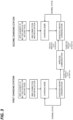
FIG. 3 is a flowchart explaining the operation state of communication means of a battery swapping station. - The present application is a battery swapping station (BSS).
FIG. 1 is a view illustrating the configuration of a typical battery swapping station.FIG. 1 illustrates the general configuration of a battery swapping station, but the configuration of the battery swapping station applicable to this application is not limited toFIG. 1 . - As illustrated in
FIG. 1 , typically, a battery swapping station may include a plurality ofcharging stations 1 to 8 installed to perform charging of a battery module or battery pack, and a plurality of charging stations may exist in the battery swapping station. In addition, the battery swapping station may include adisplay 10 configured to display the battery state of each charging station. - In this battery swapping station, communication means is required to monitor the state of a battery module or battery pack present in each charging station and share information on the state.
- In the present application, at least two types of communication means, specifically, two types of wireless communication means with different usage frequency bands, are applied as the communication means.
- For example, in the present application, as the communication means for communication with a battery management system (BMS) of a battery module or battery pack in each individual charging station when the battery management system and communication means for data transmission and reception between all of the charging stations, separate communications may be used.
- For example, the battery swapping station may include first wireless communication means installed in each individual charging station to be capable of communicating with the battery management system (BMS) of the battery module or battery pack. In the above description, the first wireless communication means may be, for example, a near-field communication (NFC) means. The first wireless communication means may be communication means for communication with the battery management system (BMS) of the battery module or battery pack in each individual charging station.
- As is well known, the near-field communication means is a technology for wireless communication at a relatively short distance using about 13.56 MHz, which is generally utilized in services such as transportation, ticketing, and/or payment. This near-field communication means may be utilized in a contact or non-contact type.
- In the present application, the first wireless communication means may be applied as communication means for communication with the battery management system (BMS) of a battery module or battery pack in each individual charging station to obtain the state of each individual battery module or battery pack.
- The method of performing communication in each individual charging station using the first wireless communication means is not particularly limited, and a general communication method may be used.
-
FIG. 2 is a schematic view illustrating a communication state in one of theindividual charging stations 1 to 8 of the battery swapping station ofFIG. 1 . - For example, when the near-field communication means is applied as the first wireless communication means as illustrated in
FIG. 2 , the communication may be performed by installing a communication chip or transmission/reception means 101 capable of communication in a battery module or battery pack or a battery management system (BMS) of the battery module or battery pack, and installing thesame means 102 in the charging station as well. - The battery swapping station of the present application may include second wireless communication means separate from the first wireless communication means, and the second wireless communication means may be used as means for mutually transmitting/receiving state information of battery modules or battery packs in the plurality of charging stations within the battery swapping station.
- That is, the second wireless communication means may be installed to enable data transmission and reception between the battery management systems of battery modules or battery packs in the plurality of charging stations of the battery swapping station.
- At this time, any communication means may be applicable as the second wireless communication means without particular limitation as long as the communication means is different from the first wireless communication means, but appropriately, second wireless communication means that utilizes a communication frequency of a higher band compared to the first wireless communication means may be applied.
- For example, the second wireless communication means may be second wireless communication means that uses a frequency in the band of about 300 MHz to 10 GHz. Examples of such second wireless communication means include but are not limited to, Bluetooth communication means or Wi-Fi communication means using a frequency of about 2.4 GHz band, Wi-Fi communication means using a frequency of about 5 GHz band, and EnOcean communication using a band of about 315 MHz, a band of 868 MHz, a band of 905 MHz, and/or a band of 902 MHz.
- In the present application, it is possible to provide a battery swapping station suitable for a purpose by controlling the operation methods of the two types of communication means.
- For example, when the battery swapping station is in a normal state, the first wireless communication means may be activated and maintained in a communication state with the battery management system (BMS), and the second wireless communication means may be controlled to be maintained in an inactive state or a reception standby state.
- In the above description, the normal state refers to a state in which an abnormal state does not occur in a battery module or battery pack before, during, or after charging of the battery module or battery pack, and in the above description, the abnormal state includes an abnormal state such as generation of abnormally high temperature or heat, overcharging, or ignition in a battery module or battery pack.
- Meanwhile, in the battery swapping station, when an emergency state occurs in at least one battery module or battery pack, control may be performed such that information on the emergency state is transmitted to the battery management system of another battery module or battery pack by the second wireless communication means.
- In the above description, the emergency state refers to a state in which an abnormal state occurs in a battery module or battery pack before, during, or after charging of the battery module or battery pack, and in the above description, the abnormal state includes an abnormal state such as generation of abnormally high temperature or heat, overcharging, or ignition in a battery module or battery pack.
- In the battery swapping station, when the battery management system in another charging station transmits the emergency state information of the charging station where the emergency state occurs, the operation of the communication means may also be controlled depending on the state of the battery management system that receives the emergency state information.
- For example, when the charging station of the battery management system that receives the emergency state information is in the normal state, the second wireless communication means of the charging station may be controlled to be maintained in an inactive state or a reception standby state. At this time, the communication state of the first wireless communication means of the charging station with the battery management system in the corresponding charging station may be maintained in the active state.
- In addition, when the charging station of the battery management system that receives the emergency state information is in an emergency state, the transmission state of the second wireless communication means of the charging station may be activated, and the information on the emergency state may be transmitted to the battery management system in another charging station by the activated second wireless communication means.
-
FIG. 3 is a flowchart for explaining the states of the communication means as described above. - For example, assuming that the battery swapping station is in a use state, a fully charged battery module or battery pack will be replaced with a discharged battery module or battery pack in at least one charging station of the battery swapping station. In
FIG. 3 , it is assumed that replacement is performed in two charging stations (first and second charging stations) of the battery swapping station. - When the battery module or battery pack is replaced as described above, each charging station may perform connection with the battery management system (BMS) and initialization and then proceed to the charging mode. However, all of the charging stations do not necessarily perform the charging mode, and may proceed to other modes such as a standby mode as needed.
- In the charging mode, the states of the battery modules or packs are diagnosed, and at this time, the first wireless communication means (NFC) is activated in the communication state and is in communication with each individual battery management system. When a battery module or pack is maintained in the normal state where no abnormal state occurs, the charging mode will continue until fully charged. In this normal state, the second wireless communication means is maintained in the inactive state or in the reception standby state.
- In the above situation, when an abnormal state occurs and an emergency station is detected in one of the charging station, transmission of the second wireless communication means is activated. At this time, the transmission states of the first wireless communication means and the second wireless communication means may be activated simultaneously. In
FIG. 3 , it is assumed that an emergency state is detected in the first charging station. When an emergency condition is detected in the first charging station as described above, the second wireless communication means transmits information on the emergency state to another charging station.FIG. 3 illustrates a case where information on the emergency state of the first charging station is transmitted to the second charging station by the second wireless communication means, but the information on the emergency state of the first charging station may be transmitted to at least some or all of the charging stations other than the first charging station in the battery swapping station. - In addition, the information transmitted in this way may also be transmitted to an integrated management system.
- The operation of the communication means of the second charging station that receives the emergency state information of the first charging station may be adjusted differently depending on the state of the second charging station.
- For example, when the second charging station is in the normal state, the first wireless communication means of the second charging station may be controlled to be maintained in the communication state with the battery management system, and the second wireless communication means may be maintained in the reception standby state or the inactive state, or may maintain the inactive state at least in terms of the transmission state.
- In contrast, when the second charging station is in an emergency state, the transmission states of the first and second wireless communication means of the second charging station may both be activated, and information on the emergency state of the second charging station may be transmitted to another charging station via the second wireless communication means.
- In the present application, by properly operating the two types of communication means as described above, it is possible to prevent communication error problems even when battery modules or packs are frequently replaced, and when an emergency state occurs, it is possible to effectively and quickly detect the location or degree of occurrence of the emergency state to cope with the emergency state.
- The present application also relates to a method of using a battery swapping station.
- Specifically, the using method may be a method of using the above-described battery swapping station which includes the plurality of charging stations each configured to perform charging of a battery module or battery pack, the first wireless communication means, and the second wireless communication means.
- The detailed description on the using method is as described in the description of the battery swapping station.
- Accordingly, the using method may include the steps of: communicating with the battery management system of the battery module or battery pack using the first wireless communication means; and controlling the state of the second wireless communication means depending on the state information of the battery module or battery pack.
- In the above description, the communication frequency band of the second wireless communication means may be higher than the communication frequency band of the first wireless communication means.
- In the using method, when the battery module or battery pack is in the normal state, the step of maintaining the second wireless communication means in an inactive state or in a reception standby state may be performed.
- In the using method, when an emergency state occurs in at least one battery module or battery pack, the step of transmitting information on the emergency state to the battery management system of another battery module or battery pack using the second wireless communication means may be performed.
- In the using method, when the charging station of the battery management system that receives the emergency state information is in the normal state when the emergency state information is transmitted, the step of maintaining the second wireless communication means of the charging station of the battery management system that receives the emergency state information in an inactive state or a reception standby state may be performed.
- In the using method, when the charging station of the battery management system that receives the emergency state information is in an emergency state when the emergency state information is transmitted, the step of transmitting the emergency state information to the battery management system of another charging station by the second wireless communication means of the charging station of the battery management system that receives the emergency state information may be performed.
Claims (14)
- A battery swapping station comprising:a plurality of charging stations each configured to perform charging of a battery module or battery pack;a first wireless communication unit installed to communicate with a battery management system of the battery module or battery pack; anda second wireless communication unit installed to enable data transmission and reception between battery management systems in the plurality of charging stations,wherein the first and second wireless communication means have different communication frequency bands.
- The battery swapping station of claim 1, wherein the communication frequency band of the second wireless communication means is higher than the communication frequency band of the first wireless communication means.
- The battery swapping station of claim 1, wherein the first wireless communication means is a non-contact or contact type near-field communication means.
- The battery swapping station of claim 1, wherein the communication frequency band of the second wireless communication means is within a range of 300 MHz to 10 GHz.
- The battery swapping station of claim 1, wherein, when the battery module or battery pack is in a normal state, the first wireless communication means is in a communication state with the battery management system, and the second wireless communication means is controlled to be in a transmission inactive state or a reception standby state.
- The battery swapping station of claim 1, wherein, when at least one battery module or battery pack is in an emergency state, control is performed such that information on the emergency state is transmitted to a battery management system of another charging station by the second wireless communication means.
- The battery swapping station of claim 6, wherein, when the charging station of the battery management system that receives the information on the emergency state is in a normal state, the second wireless communication means of the charging station is controlled to be maintained in a transmission inactive state or a reception standby state.
- The battery swapping station of claim 6, wherein, when the charging station of the battery management system that receives the information on the emergency state is in an emergency state, control is performed such that the information on the emergency state is transmitted to a battery management system in another charging station by the second wireless communication means of the charging station.
- A method of using a battery swapping station including a plurality of charging stations each configured to perform charging of a battery module or battery pack, and including first and second wireless communication means having different communication frequency bands, the method comprising:communicating with the battery management systems of the charging stations using the first wireless communication means; andcontrolling a state of the second wireless communication means according to information on a state of the battery module or battery pack.
- The method of claim 9, wherein the communication frequency band of the second wireless communication means is higher than the communication frequency band of the first wireless communication means.
- The method of claim 9, wherein, when the battery module or battery pack is in a normal state, the second wireless communication means is maintained in a transmission inactive state or a reception standby state.
- The method of claim 9, wherein, when at least one battery module or battery pack is in an emergency state, information on the emergency state is transmitted to a battery management system of another charging station by the second wireless communication means.
- The method of claim 12, wherein, when the charging station of the battery management system that has received the emergency state information is in a normal state, the second wireless communication means of the charging station is maintained in a transmission inactive state or a reception standby state.
- The method of claim 12, wherein, when the charging station of the battery management system that has received the information on the emergency state is in an emergency state, the information on the emergency state is transmitted to the battery management system in another charging station by the second wireless communication means of the charging station.
Applications Claiming Priority (2)
| Application Number | Priority Date | Filing Date | Title |
|---|---|---|---|
| KR1020220065240A KR102819854B1 (en) | 2022-05-27 | 2022-05-27 | Battery Swapping Station |
| PCT/KR2023/007229 WO2023229414A1 (en) | 2022-05-27 | 2023-05-26 | Battery swapping station |
Publications (2)
| Publication Number | Publication Date |
|---|---|
| EP4534333A1 true EP4534333A1 (en) | 2025-04-09 |
| EP4534333A4 EP4534333A4 (en) | 2025-10-01 |
Family
ID=88919729
Family Applications (1)
| Application Number | Title | Priority Date | Filing Date |
|---|---|---|---|
| EP23812188.3A Pending EP4534333A4 (en) | 2022-05-27 | 2023-05-26 | BATTERY CHANGE STATION |
Country Status (6)
| Country | Link |
|---|---|
| US (1) | US20250296468A1 (en) |
| EP (1) | EP4534333A4 (en) |
| JP (1) | JP7806307B2 (en) |
| KR (1) | KR102819854B1 (en) |
| CN (1) | CN119365361A (en) |
| WO (1) | WO2023229414A1 (en) |
Families Citing this family (1)
| Publication number | Priority date | Publication date | Assignee | Title |
|---|---|---|---|---|
| KR102755730B1 (en) * | 2024-04-16 | 2025-01-21 | 주식회사 포엔 | Battery-pack control system using short-ranged wireless communication |
Family Cites Families (11)
| Publication number | Priority date | Publication date | Assignee | Title |
|---|---|---|---|---|
| JP2003123848A (en) | 1997-09-15 | 2003-04-25 | Honda Motor Co Ltd | Battery for electric vehicle |
| KR101102618B1 (en) * | 2009-07-07 | 2012-01-03 | 경원대학교 산학협력단 | Method and system for providing additional service according to battery replacement charging of electric vehicle |
| CN102040010B (en) * | 2010-09-30 | 2014-07-23 | 国家电网公司 | Battery changing device for commercial electric vehicle and electric conversion system |
| US9285944B1 (en) * | 2011-04-22 | 2016-03-15 | Angel A. Penilla | Methods and systems for defining custom vehicle user interface configurations and cloud services for managing applications for the user interface and learned setting functions |
| JP5872354B2 (en) * | 2012-03-29 | 2016-03-01 | 株式会社日立製作所 | Battery system |
| JP6134397B2 (en) * | 2014-02-14 | 2017-05-24 | 株式会社日立製作所 | Battery control system, battery system |
| KR20210050006A (en) * | 2019-10-24 | 2021-05-07 | 주식회사 에임스 | Device for Sharing Battery by Using Near Wireless Communication |
| JP7457939B2 (en) | 2019-11-29 | 2024-03-29 | パナソニックIpマネジメント株式会社 | management system |
| JP7645196B2 (en) | 2019-12-27 | 2025-03-13 | 本田技研工業株式会社 | Control device, power supply device, program, and control method |
| KR102306805B1 (en) * | 2020-06-18 | 2021-09-30 | (주)더존시스템 | Battery exchangeable charging station and shared battery |
| KR20220065240A (en) | 2020-11-13 | 2022-05-20 | 한국전자기술연구원 | method for noise removal of images using kalman filter based on maximum corentropy |
-
2022
- 2022-05-27 KR KR1020220065240A patent/KR102819854B1/en active Active
-
2023
- 2023-05-26 WO PCT/KR2023/007229 patent/WO2023229414A1/en not_active Ceased
- 2023-05-26 EP EP23812188.3A patent/EP4534333A4/en active Pending
- 2023-05-26 CN CN202380043322.1A patent/CN119365361A/en active Pending
- 2023-05-26 JP JP2024570367A patent/JP7806307B2/en active Active
- 2023-05-26 US US18/869,639 patent/US20250296468A1/en active Pending
Also Published As
| Publication number | Publication date |
|---|---|
| WO2023229414A1 (en) | 2023-11-30 |
| JP7806307B2 (en) | 2026-01-26 |
| EP4534333A4 (en) | 2025-10-01 |
| CN119365361A (en) | 2025-01-24 |
| KR102819854B1 (en) | 2025-06-12 |
| JP2025517022A (en) | 2025-05-30 |
| US20250296468A1 (en) | 2025-09-25 |
| KR20230165475A (en) | 2023-12-05 |
Similar Documents
| Publication | Publication Date | Title |
|---|---|---|
| CN102637915B (en) | Battery, battery pack, battery charger and batter-charghing system | |
| KR102550319B1 (en) | Battery system and slave battery management system | |
| US9981559B2 (en) | Battery control system, and battery system | |
| CA2868547C (en) | Power delivery including out-of-band communication | |
| EP2634891A2 (en) | Wireless charging control method and wireless charging apparatus employing the same | |
| US10312746B2 (en) | Power providing equipment, mobile device, operating method of mobile device | |
| US20210311719A1 (en) | Method for controlling a charging station for charging vehicles and a charging station and a vehicle therefor | |
| US20250296468A1 (en) | Battery swapping station | |
| CA2547204C (en) | Inter-processor parameter management in a multiple-processor wireless mobile communication device operating on a processor specific communication network | |
| EP4095977B1 (en) | Slave bms for diagnosing an error of a battery module and battery pack comprising same slave bms | |
| KR102407416B1 (en) | Wireless power transmission and reception system | |
| US9166676B2 (en) | Telematics communication system and method | |
| WO2014098003A1 (en) | On-board equipment, communication method and recording medium | |
| EP2940828B1 (en) | A mobile device and power providing equipment for wireless charging | |
| KR20140025204A (en) | Wireless communication system for vehicle and control method thereof | |
| US12593258B2 (en) | Vehicle control system | |
| CN113071360A (en) | Wireless charging control method and system | |
| US9853710B2 (en) | Relay apparatus specifying frequency offset based on connection history and method thereof | |
| JP2017028960A (en) | Non-contact charging system, charging stand, and vehicle | |
| EP4730907A1 (en) | Communication device, base station, control method, and program | |
| EP4482221B1 (en) | Cell monitoring device, battery management system, measurement data transmission method and measurement data reception method | |
| JP4502794B2 (en) | PHS telephone apparatus and base station abnormality detection method used therefor | |
| KR20180109121A (en) | Magnetic resonance wireless charger, and operating method of the same | |
| US20210126673A1 (en) | Mobile communication device and method for providing uninterrupted power to a mobile communication device | |
| KR20250170952A (en) | Apparatus and method for power management and vehicle including apparatus |
Legal Events
| Date | Code | Title | Description |
|---|---|---|---|
| STAA | Information on the status of an ep patent application or granted ep patent |
Free format text: STATUS: THE INTERNATIONAL PUBLICATION HAS BEEN MADE |
|
| PUAI | Public reference made under article 153(3) epc to a published international application that has entered the european phase |
Free format text: ORIGINAL CODE: 0009012 |
|
| STAA | Information on the status of an ep patent application or granted ep patent |
Free format text: STATUS: REQUEST FOR EXAMINATION WAS MADE |
|
| 17P | Request for examination filed |
Effective date: 20241218 |
|
| AK | Designated contracting states |
Kind code of ref document: A1 Designated state(s): AL AT BE BG CH CY CZ DE DK EE ES FI FR GB GR HR HU IE IS IT LI LT LU LV MC ME MK MT NL NO PL PT RO RS SE SI SK SM TR |
|
| DAV | Request for validation of the european patent (deleted) | ||
| DAX | Request for extension of the european patent (deleted) | ||
| A4 | Supplementary search report drawn up and despatched |
Effective date: 20250901 |
|
| RIC1 | Information provided on ipc code assigned before grant |
Ipc: B60L 53/30 20190101AFI20250826BHEP Ipc: B60L 53/66 20190101ALI20250826BHEP Ipc: B60L 53/53 20190101ALI20250826BHEP Ipc: H04W 4/80 20180101ALI20250826BHEP Ipc: B60L 3/00 20190101ALI20250826BHEP Ipc: B60L 53/67 20190101ALI20250826BHEP Ipc: B60L 53/80 20190101ALI20250826BHEP Ipc: H01M 10/42 20060101ALI20250826BHEP Ipc: H01M 10/48 20060101ALI20250826BHEP Ipc: H02J 7/00 20060101ALI20250826BHEP |
|
| STAA | Information on the status of an ep patent application or granted ep patent |
Free format text: STATUS: EXAMINATION IS IN PROGRESS |