EP4534329A1 - Work vehicle - Google Patents
Work vehicle Download PDFInfo
- Publication number
- EP4534329A1 EP4534329A1 EP23831354.8A EP23831354A EP4534329A1 EP 4534329 A1 EP4534329 A1 EP 4534329A1 EP 23831354 A EP23831354 A EP 23831354A EP 4534329 A1 EP4534329 A1 EP 4534329A1
- Authority
- EP
- European Patent Office
- Prior art keywords
- fuel
- implement
- work vehicle
- work
- type
- Prior art date
- Legal status (The legal status is an assumption and is not a legal conclusion. Google has not performed a legal analysis and makes no representation as to the accuracy of the status listed.)
- Pending
Links
Images







Classifications
-
- B—PERFORMING OPERATIONS; TRANSPORTING
- B60—VEHICLES IN GENERAL
- B60L—PROPULSION OF ELECTRICALLY-PROPELLED VEHICLES; SUPPLYING ELECTRIC POWER FOR AUXILIARY EQUIPMENT OF ELECTRICALLY-PROPELLED VEHICLES; ELECTRODYNAMIC BRAKE SYSTEMS FOR VEHICLES IN GENERAL; MAGNETIC SUSPENSION OR LEVITATION FOR VEHICLES; MONITORING OPERATING VARIABLES OF ELECTRICALLY-PROPELLED VEHICLES; ELECTRIC SAFETY DEVICES FOR ELECTRICALLY-PROPELLED VEHICLES
- B60L50/00—Electric propulsion with power supplied within the vehicle
- B60L50/50—Electric propulsion with power supplied within the vehicle using propulsion power supplied by batteries or fuel cells
- B60L50/70—Electric propulsion with power supplied within the vehicle using propulsion power supplied by batteries or fuel cells using power supplied by fuel cells
-
- A—HUMAN NECESSITIES
- A01—AGRICULTURE; FORESTRY; ANIMAL HUSBANDRY; HUNTING; TRAPPING; FISHING
- A01B—SOIL WORKING IN AGRICULTURE OR FORESTRY; PARTS, DETAILS, OR ACCESSORIES OF AGRICULTURAL MACHINES OR IMPLEMENTS, IN GENERAL
- A01B76/00—Parts, details or accessories of agricultural machines or implements, not provided for in groups A01B51/00 - A01B75/00
-
- B—PERFORMING OPERATIONS; TRANSPORTING
- B60—VEHICLES IN GENERAL
- B60K—ARRANGEMENT OR MOUNTING OF PROPULSION UNITS OR OF TRANSMISSIONS IN VEHICLES; ARRANGEMENT OR MOUNTING OF PLURAL DIVERSE PRIME-MOVERS IN VEHICLES; AUXILIARY DRIVES FOR VEHICLES; INSTRUMENTATION OR DASHBOARDS FOR VEHICLES; ARRANGEMENTS IN CONNECTION WITH COOLING, AIR INTAKE, GAS EXHAUST OR FUEL SUPPLY OF PROPULSION UNITS IN VEHICLES
- B60K35/00—Instruments specially adapted for vehicles; Arrangement of instruments in or on vehicles
- B60K35/10—Input arrangements, i.e. from user to vehicle, associated with vehicle functions or specially adapted therefor
-
- B—PERFORMING OPERATIONS; TRANSPORTING
- B60—VEHICLES IN GENERAL
- B60K—ARRANGEMENT OR MOUNTING OF PROPULSION UNITS OR OF TRANSMISSIONS IN VEHICLES; ARRANGEMENT OR MOUNTING OF PLURAL DIVERSE PRIME-MOVERS IN VEHICLES; AUXILIARY DRIVES FOR VEHICLES; INSTRUMENTATION OR DASHBOARDS FOR VEHICLES; ARRANGEMENTS IN CONNECTION WITH COOLING, AIR INTAKE, GAS EXHAUST OR FUEL SUPPLY OF PROPULSION UNITS IN VEHICLES
- B60K35/00—Instruments specially adapted for vehicles; Arrangement of instruments in or on vehicles
- B60K35/20—Output arrangements, i.e. from vehicle to user, associated with vehicle functions or specially adapted therefor
- B60K35/21—Output arrangements, i.e. from vehicle to user, associated with vehicle functions or specially adapted therefor using visual output, e.g. blinking lights or matrix displays
- B60K35/22—Display screens
-
- B—PERFORMING OPERATIONS; TRANSPORTING
- B60—VEHICLES IN GENERAL
- B60K—ARRANGEMENT OR MOUNTING OF PROPULSION UNITS OR OF TRANSMISSIONS IN VEHICLES; ARRANGEMENT OR MOUNTING OF PLURAL DIVERSE PRIME-MOVERS IN VEHICLES; AUXILIARY DRIVES FOR VEHICLES; INSTRUMENTATION OR DASHBOARDS FOR VEHICLES; ARRANGEMENTS IN CONNECTION WITH COOLING, AIR INTAKE, GAS EXHAUST OR FUEL SUPPLY OF PROPULSION UNITS IN VEHICLES
- B60K35/00—Instruments specially adapted for vehicles; Arrangement of instruments in or on vehicles
- B60K35/20—Output arrangements, i.e. from vehicle to user, associated with vehicle functions or specially adapted therefor
- B60K35/28—Output arrangements, i.e. from vehicle to user, associated with vehicle functions or specially adapted therefor characterised by the type of the output information, e.g. video entertainment or vehicle dynamics information; characterised by the purpose of the output information, e.g. for attracting the attention of the driver
-
- B—PERFORMING OPERATIONS; TRANSPORTING
- B60—VEHICLES IN GENERAL
- B60L—PROPULSION OF ELECTRICALLY-PROPELLED VEHICLES; SUPPLYING ELECTRIC POWER FOR AUXILIARY EQUIPMENT OF ELECTRICALLY-PROPELLED VEHICLES; ELECTRODYNAMIC BRAKE SYSTEMS FOR VEHICLES IN GENERAL; MAGNETIC SUSPENSION OR LEVITATION FOR VEHICLES; MONITORING OPERATING VARIABLES OF ELECTRICALLY-PROPELLED VEHICLES; ELECTRIC SAFETY DEVICES FOR ELECTRICALLY-PROPELLED VEHICLES
- B60L1/00—Supplying electric power to auxiliary equipment of vehicles
-
- B—PERFORMING OPERATIONS; TRANSPORTING
- B60—VEHICLES IN GENERAL
- B60L—PROPULSION OF ELECTRICALLY-PROPELLED VEHICLES; SUPPLYING ELECTRIC POWER FOR AUXILIARY EQUIPMENT OF ELECTRICALLY-PROPELLED VEHICLES; ELECTRODYNAMIC BRAKE SYSTEMS FOR VEHICLES IN GENERAL; MAGNETIC SUSPENSION OR LEVITATION FOR VEHICLES; MONITORING OPERATING VARIABLES OF ELECTRICALLY-PROPELLED VEHICLES; ELECTRIC SAFETY DEVICES FOR ELECTRICALLY-PROPELLED VEHICLES
- B60L1/00—Supplying electric power to auxiliary equipment of vehicles
- B60L1/003—Supplying electric power to auxiliary equipment of vehicles to auxiliary motors, e.g. for pumps, compressors
-
- B—PERFORMING OPERATIONS; TRANSPORTING
- B60—VEHICLES IN GENERAL
- B60L—PROPULSION OF ELECTRICALLY-PROPELLED VEHICLES; SUPPLYING ELECTRIC POWER FOR AUXILIARY EQUIPMENT OF ELECTRICALLY-PROPELLED VEHICLES; ELECTRODYNAMIC BRAKE SYSTEMS FOR VEHICLES IN GENERAL; MAGNETIC SUSPENSION OR LEVITATION FOR VEHICLES; MONITORING OPERATING VARIABLES OF ELECTRICALLY-PROPELLED VEHICLES; ELECTRIC SAFETY DEVICES FOR ELECTRICALLY-PROPELLED VEHICLES
- B60L1/00—Supplying electric power to auxiliary equipment of vehicles
- B60L1/006—Supplying electric power to auxiliary equipment of vehicles to power outlets
-
- B—PERFORMING OPERATIONS; TRANSPORTING
- B60—VEHICLES IN GENERAL
- B60L—PROPULSION OF ELECTRICALLY-PROPELLED VEHICLES; SUPPLYING ELECTRIC POWER FOR AUXILIARY EQUIPMENT OF ELECTRICALLY-PROPELLED VEHICLES; ELECTRODYNAMIC BRAKE SYSTEMS FOR VEHICLES IN GENERAL; MAGNETIC SUSPENSION OR LEVITATION FOR VEHICLES; MONITORING OPERATING VARIABLES OF ELECTRICALLY-PROPELLED VEHICLES; ELECTRIC SAFETY DEVICES FOR ELECTRICALLY-PROPELLED VEHICLES
- B60L3/00—Electric devices on electrically-propelled vehicles for safety purposes; Monitoring operating variables, e.g. speed, deceleration or energy consumption
- B60L3/0023—Detecting, eliminating, remedying or compensating for drive train abnormalities, e.g. failures within the drive train
- B60L3/0046—Detecting, eliminating, remedying or compensating for drive train abnormalities, e.g. failures within the drive train relating to electric energy storage systems, e.g. batteries or capacitors
-
- B—PERFORMING OPERATIONS; TRANSPORTING
- B60—VEHICLES IN GENERAL
- B60L—PROPULSION OF ELECTRICALLY-PROPELLED VEHICLES; SUPPLYING ELECTRIC POWER FOR AUXILIARY EQUIPMENT OF ELECTRICALLY-PROPELLED VEHICLES; ELECTRODYNAMIC BRAKE SYSTEMS FOR VEHICLES IN GENERAL; MAGNETIC SUSPENSION OR LEVITATION FOR VEHICLES; MONITORING OPERATING VARIABLES OF ELECTRICALLY-PROPELLED VEHICLES; ELECTRIC SAFETY DEVICES FOR ELECTRICALLY-PROPELLED VEHICLES
- B60L3/00—Electric devices on electrically-propelled vehicles for safety purposes; Monitoring operating variables, e.g. speed, deceleration or energy consumption
- B60L3/12—Recording operating variables ; Monitoring of operating variables
-
- B—PERFORMING OPERATIONS; TRANSPORTING
- B60—VEHICLES IN GENERAL
- B60L—PROPULSION OF ELECTRICALLY-PROPELLED VEHICLES; SUPPLYING ELECTRIC POWER FOR AUXILIARY EQUIPMENT OF ELECTRICALLY-PROPELLED VEHICLES; ELECTRODYNAMIC BRAKE SYSTEMS FOR VEHICLES IN GENERAL; MAGNETIC SUSPENSION OR LEVITATION FOR VEHICLES; MONITORING OPERATING VARIABLES OF ELECTRICALLY-PROPELLED VEHICLES; ELECTRIC SAFETY DEVICES FOR ELECTRICALLY-PROPELLED VEHICLES
- B60L50/00—Electric propulsion with power supplied within the vehicle
- B60L50/50—Electric propulsion with power supplied within the vehicle using propulsion power supplied by batteries or fuel cells
- B60L50/51—Electric propulsion with power supplied within the vehicle using propulsion power supplied by batteries or fuel cells characterised by AC-motors
-
- B—PERFORMING OPERATIONS; TRANSPORTING
- B60—VEHICLES IN GENERAL
- B60L—PROPULSION OF ELECTRICALLY-PROPELLED VEHICLES; SUPPLYING ELECTRIC POWER FOR AUXILIARY EQUIPMENT OF ELECTRICALLY-PROPELLED VEHICLES; ELECTRODYNAMIC BRAKE SYSTEMS FOR VEHICLES IN GENERAL; MAGNETIC SUSPENSION OR LEVITATION FOR VEHICLES; MONITORING OPERATING VARIABLES OF ELECTRICALLY-PROPELLED VEHICLES; ELECTRIC SAFETY DEVICES FOR ELECTRICALLY-PROPELLED VEHICLES
- B60L50/00—Electric propulsion with power supplied within the vehicle
- B60L50/50—Electric propulsion with power supplied within the vehicle using propulsion power supplied by batteries or fuel cells
- B60L50/70—Electric propulsion with power supplied within the vehicle using propulsion power supplied by batteries or fuel cells using power supplied by fuel cells
- B60L50/71—Arrangement of fuel cells within vehicles specially adapted for electric vehicles
-
- B—PERFORMING OPERATIONS; TRANSPORTING
- B60—VEHICLES IN GENERAL
- B60L—PROPULSION OF ELECTRICALLY-PROPELLED VEHICLES; SUPPLYING ELECTRIC POWER FOR AUXILIARY EQUIPMENT OF ELECTRICALLY-PROPELLED VEHICLES; ELECTRODYNAMIC BRAKE SYSTEMS FOR VEHICLES IN GENERAL; MAGNETIC SUSPENSION OR LEVITATION FOR VEHICLES; MONITORING OPERATING VARIABLES OF ELECTRICALLY-PROPELLED VEHICLES; ELECTRIC SAFETY DEVICES FOR ELECTRICALLY-PROPELLED VEHICLES
- B60L50/00—Electric propulsion with power supplied within the vehicle
- B60L50/50—Electric propulsion with power supplied within the vehicle using propulsion power supplied by batteries or fuel cells
- B60L50/70—Electric propulsion with power supplied within the vehicle using propulsion power supplied by batteries or fuel cells using power supplied by fuel cells
- B60L50/72—Constructional details of fuel cells specially adapted for electric vehicles
-
- B—PERFORMING OPERATIONS; TRANSPORTING
- B60—VEHICLES IN GENERAL
- B60L—PROPULSION OF ELECTRICALLY-PROPELLED VEHICLES; SUPPLYING ELECTRIC POWER FOR AUXILIARY EQUIPMENT OF ELECTRICALLY-PROPELLED VEHICLES; ELECTRODYNAMIC BRAKE SYSTEMS FOR VEHICLES IN GENERAL; MAGNETIC SUSPENSION OR LEVITATION FOR VEHICLES; MONITORING OPERATING VARIABLES OF ELECTRICALLY-PROPELLED VEHICLES; ELECTRIC SAFETY DEVICES FOR ELECTRICALLY-PROPELLED VEHICLES
- B60L50/00—Electric propulsion with power supplied within the vehicle
- B60L50/50—Electric propulsion with power supplied within the vehicle using propulsion power supplied by batteries or fuel cells
- B60L50/75—Electric propulsion with power supplied within the vehicle using propulsion power supplied by batteries or fuel cells using propulsion power supplied by both fuel cells and batteries
-
- B—PERFORMING OPERATIONS; TRANSPORTING
- B60—VEHICLES IN GENERAL
- B60L—PROPULSION OF ELECTRICALLY-PROPELLED VEHICLES; SUPPLYING ELECTRIC POWER FOR AUXILIARY EQUIPMENT OF ELECTRICALLY-PROPELLED VEHICLES; ELECTRODYNAMIC BRAKE SYSTEMS FOR VEHICLES IN GENERAL; MAGNETIC SUSPENSION OR LEVITATION FOR VEHICLES; MONITORING OPERATING VARIABLES OF ELECTRICALLY-PROPELLED VEHICLES; ELECTRIC SAFETY DEVICES FOR ELECTRICALLY-PROPELLED VEHICLES
- B60L53/00—Methods of charging batteries, specially adapted for electric vehicles; Charging stations or on-board charging equipment therefor; Exchange of energy storage elements in electric vehicles
- B60L53/60—Monitoring or controlling charging stations
- B60L53/66—Data transfer between charging stations and vehicles
- B60L53/665—Methods related to measuring, billing or payment
-
- B—PERFORMING OPERATIONS; TRANSPORTING
- B60—VEHICLES IN GENERAL
- B60L—PROPULSION OF ELECTRICALLY-PROPELLED VEHICLES; SUPPLYING ELECTRIC POWER FOR AUXILIARY EQUIPMENT OF ELECTRICALLY-PROPELLED VEHICLES; ELECTRODYNAMIC BRAKE SYSTEMS FOR VEHICLES IN GENERAL; MAGNETIC SUSPENSION OR LEVITATION FOR VEHICLES; MONITORING OPERATING VARIABLES OF ELECTRICALLY-PROPELLED VEHICLES; ELECTRIC SAFETY DEVICES FOR ELECTRICALLY-PROPELLED VEHICLES
- B60L58/00—Methods or circuit arrangements for monitoring or controlling batteries or fuel cells, specially adapted for electric vehicles
- B60L58/10—Methods or circuit arrangements for monitoring or controlling batteries or fuel cells, specially adapted for electric vehicles for monitoring or controlling batteries
- B60L58/12—Methods or circuit arrangements for monitoring or controlling batteries or fuel cells, specially adapted for electric vehicles for monitoring or controlling batteries responding to state of charge [SoC]
-
- B—PERFORMING OPERATIONS; TRANSPORTING
- B60—VEHICLES IN GENERAL
- B60L—PROPULSION OF ELECTRICALLY-PROPELLED VEHICLES; SUPPLYING ELECTRIC POWER FOR AUXILIARY EQUIPMENT OF ELECTRICALLY-PROPELLED VEHICLES; ELECTRODYNAMIC BRAKE SYSTEMS FOR VEHICLES IN GENERAL; MAGNETIC SUSPENSION OR LEVITATION FOR VEHICLES; MONITORING OPERATING VARIABLES OF ELECTRICALLY-PROPELLED VEHICLES; ELECTRIC SAFETY DEVICES FOR ELECTRICALLY-PROPELLED VEHICLES
- B60L58/00—Methods or circuit arrangements for monitoring or controlling batteries or fuel cells, specially adapted for electric vehicles
- B60L58/10—Methods or circuit arrangements for monitoring or controlling batteries or fuel cells, specially adapted for electric vehicles for monitoring or controlling batteries
- B60L58/12—Methods or circuit arrangements for monitoring or controlling batteries or fuel cells, specially adapted for electric vehicles for monitoring or controlling batteries responding to state of charge [SoC]
- B60L58/14—Preventing excessive discharging
-
- B—PERFORMING OPERATIONS; TRANSPORTING
- B60—VEHICLES IN GENERAL
- B60L—PROPULSION OF ELECTRICALLY-PROPELLED VEHICLES; SUPPLYING ELECTRIC POWER FOR AUXILIARY EQUIPMENT OF ELECTRICALLY-PROPELLED VEHICLES; ELECTRODYNAMIC BRAKE SYSTEMS FOR VEHICLES IN GENERAL; MAGNETIC SUSPENSION OR LEVITATION FOR VEHICLES; MONITORING OPERATING VARIABLES OF ELECTRICALLY-PROPELLED VEHICLES; ELECTRIC SAFETY DEVICES FOR ELECTRICALLY-PROPELLED VEHICLES
- B60L58/00—Methods or circuit arrangements for monitoring or controlling batteries or fuel cells, specially adapted for electric vehicles
- B60L58/10—Methods or circuit arrangements for monitoring or controlling batteries or fuel cells, specially adapted for electric vehicles for monitoring or controlling batteries
- B60L58/18—Methods or circuit arrangements for monitoring or controlling batteries or fuel cells, specially adapted for electric vehicles for monitoring or controlling batteries of two or more battery modules
- B60L58/22—Balancing the charge of battery modules
-
- B—PERFORMING OPERATIONS; TRANSPORTING
- B60—VEHICLES IN GENERAL
- B60L—PROPULSION OF ELECTRICALLY-PROPELLED VEHICLES; SUPPLYING ELECTRIC POWER FOR AUXILIARY EQUIPMENT OF ELECTRICALLY-PROPELLED VEHICLES; ELECTRODYNAMIC BRAKE SYSTEMS FOR VEHICLES IN GENERAL; MAGNETIC SUSPENSION OR LEVITATION FOR VEHICLES; MONITORING OPERATING VARIABLES OF ELECTRICALLY-PROPELLED VEHICLES; ELECTRIC SAFETY DEVICES FOR ELECTRICALLY-PROPELLED VEHICLES
- B60L58/00—Methods or circuit arrangements for monitoring or controlling batteries or fuel cells, specially adapted for electric vehicles
- B60L58/30—Methods or circuit arrangements for monitoring or controlling batteries or fuel cells, specially adapted for electric vehicles for monitoring or controlling fuel cells
-
- B—PERFORMING OPERATIONS; TRANSPORTING
- B60—VEHICLES IN GENERAL
- B60Q—ARRANGEMENT OF SIGNALLING OR LIGHTING DEVICES, THE MOUNTING OR SUPPORTING THEREOF OR CIRCUITS THEREFOR, FOR VEHICLES IN GENERAL
- B60Q5/00—Arrangement or adaptation of acoustic signal devices
- B60Q5/005—Arrangement or adaptation of acoustic signal devices automatically actuated
-
- G—PHYSICS
- G07—CHECKING-DEVICES
- G07C—TIME OR ATTENDANCE REGISTERS; REGISTERING OR INDICATING THE WORKING OF MACHINES; GENERATING RANDOM NUMBERS; VOTING OR LOTTERY APPARATUS; ARRANGEMENTS, SYSTEMS OR APPARATUS FOR CHECKING NOT PROVIDED FOR ELSEWHERE
- G07C5/00—Registering or indicating the working of vehicles
- G07C5/004—Indicating the operating range of the engine
-
- B—PERFORMING OPERATIONS; TRANSPORTING
- B60—VEHICLES IN GENERAL
- B60K—ARRANGEMENT OR MOUNTING OF PROPULSION UNITS OR OF TRANSMISSIONS IN VEHICLES; ARRANGEMENT OR MOUNTING OF PLURAL DIVERSE PRIME-MOVERS IN VEHICLES; AUXILIARY DRIVES FOR VEHICLES; INSTRUMENTATION OR DASHBOARDS FOR VEHICLES; ARRANGEMENTS IN CONNECTION WITH COOLING, AIR INTAKE, GAS EXHAUST OR FUEL SUPPLY OF PROPULSION UNITS IN VEHICLES
- B60K2360/00—Indexing scheme associated with groups B60K35/00 or B60K37/00 relating to details of instruments or dashboards
- B60K2360/16—Type of output information
- B60K2360/166—Navigation
-
- B—PERFORMING OPERATIONS; TRANSPORTING
- B60—VEHICLES IN GENERAL
- B60K—ARRANGEMENT OR MOUNTING OF PROPULSION UNITS OR OF TRANSMISSIONS IN VEHICLES; ARRANGEMENT OR MOUNTING OF PLURAL DIVERSE PRIME-MOVERS IN VEHICLES; AUXILIARY DRIVES FOR VEHICLES; INSTRUMENTATION OR DASHBOARDS FOR VEHICLES; ARRANGEMENTS IN CONNECTION WITH COOLING, AIR INTAKE, GAS EXHAUST OR FUEL SUPPLY OF PROPULSION UNITS IN VEHICLES
- B60K2360/00—Indexing scheme associated with groups B60K35/00 or B60K37/00 relating to details of instruments or dashboards
- B60K2360/16—Type of output information
- B60K2360/169—Remaining operating distance or charge
-
- B—PERFORMING OPERATIONS; TRANSPORTING
- B60—VEHICLES IN GENERAL
- B60K—ARRANGEMENT OR MOUNTING OF PROPULSION UNITS OR OF TRANSMISSIONS IN VEHICLES; ARRANGEMENT OR MOUNTING OF PLURAL DIVERSE PRIME-MOVERS IN VEHICLES; AUXILIARY DRIVES FOR VEHICLES; INSTRUMENTATION OR DASHBOARDS FOR VEHICLES; ARRANGEMENTS IN CONNECTION WITH COOLING, AIR INTAKE, GAS EXHAUST OR FUEL SUPPLY OF PROPULSION UNITS IN VEHICLES
- B60K2360/00—Indexing scheme associated with groups B60K35/00 or B60K37/00 relating to details of instruments or dashboards
- B60K2360/16—Type of output information
- B60K2360/178—Warnings
-
- B—PERFORMING OPERATIONS; TRANSPORTING
- B60—VEHICLES IN GENERAL
- B60K—ARRANGEMENT OR MOUNTING OF PROPULSION UNITS OR OF TRANSMISSIONS IN VEHICLES; ARRANGEMENT OR MOUNTING OF PLURAL DIVERSE PRIME-MOVERS IN VEHICLES; AUXILIARY DRIVES FOR VEHICLES; INSTRUMENTATION OR DASHBOARDS FOR VEHICLES; ARRANGEMENTS IN CONNECTION WITH COOLING, AIR INTAKE, GAS EXHAUST OR FUEL SUPPLY OF PROPULSION UNITS IN VEHICLES
- B60K25/00—Auxiliary drives
- B60K25/06—Auxiliary drives from the transmission power take-off
-
- B—PERFORMING OPERATIONS; TRANSPORTING
- B60—VEHICLES IN GENERAL
- B60L—PROPULSION OF ELECTRICALLY-PROPELLED VEHICLES; SUPPLYING ELECTRIC POWER FOR AUXILIARY EQUIPMENT OF ELECTRICALLY-PROPELLED VEHICLES; ELECTRODYNAMIC BRAKE SYSTEMS FOR VEHICLES IN GENERAL; MAGNETIC SUSPENSION OR LEVITATION FOR VEHICLES; MONITORING OPERATING VARIABLES OF ELECTRICALLY-PROPELLED VEHICLES; ELECTRIC SAFETY DEVICES FOR ELECTRICALLY-PROPELLED VEHICLES
- B60L2200/00—Type of vehicles
- B60L2200/40—Working vehicles
-
- B—PERFORMING OPERATIONS; TRANSPORTING
- B60—VEHICLES IN GENERAL
- B60L—PROPULSION OF ELECTRICALLY-PROPELLED VEHICLES; SUPPLYING ELECTRIC POWER FOR AUXILIARY EQUIPMENT OF ELECTRICALLY-PROPELLED VEHICLES; ELECTRODYNAMIC BRAKE SYSTEMS FOR VEHICLES IN GENERAL; MAGNETIC SUSPENSION OR LEVITATION FOR VEHICLES; MONITORING OPERATING VARIABLES OF ELECTRICALLY-PROPELLED VEHICLES; ELECTRIC SAFETY DEVICES FOR ELECTRICALLY-PROPELLED VEHICLES
- B60L2210/00—Converter types
- B60L2210/10—DC to DC converters
-
- B—PERFORMING OPERATIONS; TRANSPORTING
- B60—VEHICLES IN GENERAL
- B60L—PROPULSION OF ELECTRICALLY-PROPELLED VEHICLES; SUPPLYING ELECTRIC POWER FOR AUXILIARY EQUIPMENT OF ELECTRICALLY-PROPELLED VEHICLES; ELECTRODYNAMIC BRAKE SYSTEMS FOR VEHICLES IN GENERAL; MAGNETIC SUSPENSION OR LEVITATION FOR VEHICLES; MONITORING OPERATING VARIABLES OF ELECTRICALLY-PROPELLED VEHICLES; ELECTRIC SAFETY DEVICES FOR ELECTRICALLY-PROPELLED VEHICLES
- B60L2210/00—Converter types
- B60L2210/40—DC to AC converters
-
- B—PERFORMING OPERATIONS; TRANSPORTING
- B60—VEHICLES IN GENERAL
- B60L—PROPULSION OF ELECTRICALLY-PROPELLED VEHICLES; SUPPLYING ELECTRIC POWER FOR AUXILIARY EQUIPMENT OF ELECTRICALLY-PROPELLED VEHICLES; ELECTRODYNAMIC BRAKE SYSTEMS FOR VEHICLES IN GENERAL; MAGNETIC SUSPENSION OR LEVITATION FOR VEHICLES; MONITORING OPERATING VARIABLES OF ELECTRICALLY-PROPELLED VEHICLES; ELECTRIC SAFETY DEVICES FOR ELECTRICALLY-PROPELLED VEHICLES
- B60L2240/00—Control parameters of input or output; Target parameters
- B60L2240/10—Vehicle control parameters
- B60L2240/12—Speed
-
- B—PERFORMING OPERATIONS; TRANSPORTING
- B60—VEHICLES IN GENERAL
- B60L—PROPULSION OF ELECTRICALLY-PROPELLED VEHICLES; SUPPLYING ELECTRIC POWER FOR AUXILIARY EQUIPMENT OF ELECTRICALLY-PROPELLED VEHICLES; ELECTRODYNAMIC BRAKE SYSTEMS FOR VEHICLES IN GENERAL; MAGNETIC SUSPENSION OR LEVITATION FOR VEHICLES; MONITORING OPERATING VARIABLES OF ELECTRICALLY-PROPELLED VEHICLES; ELECTRIC SAFETY DEVICES FOR ELECTRICALLY-PROPELLED VEHICLES
- B60L2240/00—Control parameters of input or output; Target parameters
- B60L2240/10—Vehicle control parameters
- B60L2240/36—Temperature of vehicle components or parts
-
- B—PERFORMING OPERATIONS; TRANSPORTING
- B60—VEHICLES IN GENERAL
- B60L—PROPULSION OF ELECTRICALLY-PROPELLED VEHICLES; SUPPLYING ELECTRIC POWER FOR AUXILIARY EQUIPMENT OF ELECTRICALLY-PROPELLED VEHICLES; ELECTRODYNAMIC BRAKE SYSTEMS FOR VEHICLES IN GENERAL; MAGNETIC SUSPENSION OR LEVITATION FOR VEHICLES; MONITORING OPERATING VARIABLES OF ELECTRICALLY-PROPELLED VEHICLES; ELECTRIC SAFETY DEVICES FOR ELECTRICALLY-PROPELLED VEHICLES
- B60L2240/00—Control parameters of input or output; Target parameters
- B60L2240/40—Drive Train control parameters
- B60L2240/42—Drive Train control parameters related to electric machines
- B60L2240/421—Speed
-
- B—PERFORMING OPERATIONS; TRANSPORTING
- B60—VEHICLES IN GENERAL
- B60L—PROPULSION OF ELECTRICALLY-PROPELLED VEHICLES; SUPPLYING ELECTRIC POWER FOR AUXILIARY EQUIPMENT OF ELECTRICALLY-PROPELLED VEHICLES; ELECTRODYNAMIC BRAKE SYSTEMS FOR VEHICLES IN GENERAL; MAGNETIC SUSPENSION OR LEVITATION FOR VEHICLES; MONITORING OPERATING VARIABLES OF ELECTRICALLY-PROPELLED VEHICLES; ELECTRIC SAFETY DEVICES FOR ELECTRICALLY-PROPELLED VEHICLES
- B60L2240/00—Control parameters of input or output; Target parameters
- B60L2240/40—Drive Train control parameters
- B60L2240/54—Drive Train control parameters related to batteries
- B60L2240/545—Temperature
-
- B—PERFORMING OPERATIONS; TRANSPORTING
- B60—VEHICLES IN GENERAL
- B60L—PROPULSION OF ELECTRICALLY-PROPELLED VEHICLES; SUPPLYING ELECTRIC POWER FOR AUXILIARY EQUIPMENT OF ELECTRICALLY-PROPELLED VEHICLES; ELECTRODYNAMIC BRAKE SYSTEMS FOR VEHICLES IN GENERAL; MAGNETIC SUSPENSION OR LEVITATION FOR VEHICLES; MONITORING OPERATING VARIABLES OF ELECTRICALLY-PROPELLED VEHICLES; ELECTRIC SAFETY DEVICES FOR ELECTRICALLY-PROPELLED VEHICLES
- B60L2240/00—Control parameters of input or output; Target parameters
- B60L2240/40—Drive Train control parameters
- B60L2240/54—Drive Train control parameters related to batteries
- B60L2240/547—Voltage
-
- B—PERFORMING OPERATIONS; TRANSPORTING
- B60—VEHICLES IN GENERAL
- B60L—PROPULSION OF ELECTRICALLY-PROPELLED VEHICLES; SUPPLYING ELECTRIC POWER FOR AUXILIARY EQUIPMENT OF ELECTRICALLY-PROPELLED VEHICLES; ELECTRODYNAMIC BRAKE SYSTEMS FOR VEHICLES IN GENERAL; MAGNETIC SUSPENSION OR LEVITATION FOR VEHICLES; MONITORING OPERATING VARIABLES OF ELECTRICALLY-PROPELLED VEHICLES; ELECTRIC SAFETY DEVICES FOR ELECTRICALLY-PROPELLED VEHICLES
- B60L2240/00—Control parameters of input or output; Target parameters
- B60L2240/40—Drive Train control parameters
- B60L2240/54—Drive Train control parameters related to batteries
- B60L2240/549—Current
-
- B—PERFORMING OPERATIONS; TRANSPORTING
- B60—VEHICLES IN GENERAL
- B60L—PROPULSION OF ELECTRICALLY-PROPELLED VEHICLES; SUPPLYING ELECTRIC POWER FOR AUXILIARY EQUIPMENT OF ELECTRICALLY-PROPELLED VEHICLES; ELECTRODYNAMIC BRAKE SYSTEMS FOR VEHICLES IN GENERAL; MAGNETIC SUSPENSION OR LEVITATION FOR VEHICLES; MONITORING OPERATING VARIABLES OF ELECTRICALLY-PROPELLED VEHICLES; ELECTRIC SAFETY DEVICES FOR ELECTRICALLY-PROPELLED VEHICLES
- B60L2250/00—Driver interactions
- B60L2250/10—Driver interactions by alarm
-
- B—PERFORMING OPERATIONS; TRANSPORTING
- B60—VEHICLES IN GENERAL
- B60L—PROPULSION OF ELECTRICALLY-PROPELLED VEHICLES; SUPPLYING ELECTRIC POWER FOR AUXILIARY EQUIPMENT OF ELECTRICALLY-PROPELLED VEHICLES; ELECTRODYNAMIC BRAKE SYSTEMS FOR VEHICLES IN GENERAL; MAGNETIC SUSPENSION OR LEVITATION FOR VEHICLES; MONITORING OPERATING VARIABLES OF ELECTRICALLY-PROPELLED VEHICLES; ELECTRIC SAFETY DEVICES FOR ELECTRICALLY-PROPELLED VEHICLES
- B60L2250/00—Driver interactions
- B60L2250/16—Driver interactions by display
-
- B—PERFORMING OPERATIONS; TRANSPORTING
- B60—VEHICLES IN GENERAL
- B60L—PROPULSION OF ELECTRICALLY-PROPELLED VEHICLES; SUPPLYING ELECTRIC POWER FOR AUXILIARY EQUIPMENT OF ELECTRICALLY-PROPELLED VEHICLES; ELECTRODYNAMIC BRAKE SYSTEMS FOR VEHICLES IN GENERAL; MAGNETIC SUSPENSION OR LEVITATION FOR VEHICLES; MONITORING OPERATING VARIABLES OF ELECTRICALLY-PROPELLED VEHICLES; ELECTRIC SAFETY DEVICES FOR ELECTRICALLY-PROPELLED VEHICLES
- B60L2260/00—Operating Modes
- B60L2260/40—Control modes
- B60L2260/44—Control modes by parameter estimation
-
- Y—GENERAL TAGGING OF NEW TECHNOLOGICAL DEVELOPMENTS; GENERAL TAGGING OF CROSS-SECTIONAL TECHNOLOGIES SPANNING OVER SEVERAL SECTIONS OF THE IPC; TECHNICAL SUBJECTS COVERED BY FORMER USPC CROSS-REFERENCE ART COLLECTIONS [XRACs] AND DIGESTS
- Y02—TECHNOLOGIES OR APPLICATIONS FOR MITIGATION OR ADAPTATION AGAINST CLIMATE CHANGE
- Y02E—REDUCTION OF GREENHOUSE GAS [GHG] EMISSIONS, RELATED TO ENERGY GENERATION, TRANSMISSION OR DISTRIBUTION
- Y02E60/00—Enabling technologies; Technologies with a potential or indirect contribution to GHG emissions mitigation
- Y02E60/30—Hydrogen technology
- Y02E60/50—Fuel cells
-
- Y—GENERAL TAGGING OF NEW TECHNOLOGICAL DEVELOPMENTS; GENERAL TAGGING OF CROSS-SECTIONAL TECHNOLOGIES SPANNING OVER SEVERAL SECTIONS OF THE IPC; TECHNICAL SUBJECTS COVERED BY FORMER USPC CROSS-REFERENCE ART COLLECTIONS [XRACs] AND DIGESTS
- Y02—TECHNOLOGIES OR APPLICATIONS FOR MITIGATION OR ADAPTATION AGAINST CLIMATE CHANGE
- Y02T—CLIMATE CHANGE MITIGATION TECHNOLOGIES RELATED TO TRANSPORTATION
- Y02T90/00—Enabling technologies or technologies with a potential or indirect contribution to GHG emissions mitigation
- Y02T90/40—Application of hydrogen technology to transportation, e.g. using fuel cells
Definitions
- the present disclosure relates to work vehicles.
- Patent Document 1 discloses a vehicle including a fuel cell, a battery, a drive device to convert power generated by the fuel cell and battery into motive power, and a display device to display an indicator showing the power output from the fuel cell and battery.
- the display device displays information on the indicator showing a threshold used to determine whether to supply power to the drive device from either the fuel cell or battery, or from both the fuel cell and battery.
- a work vehicle includes: a fuel cell module including a fuel cell stack; at least one fuel tank to store fuel to be supplied to the fuel cell stack; a sensor to measure a remaining amount of fuel in the fuel tank; a motor connected to the fuel cell module; a power take-off shaft to be driven by the motor and to which an implement is connected; a display device; and a processing device to estimate, based on the measured remaining amount of fuel and a type of the implement connected to the power take-off shaft and/or a type of work performed by the implement, at least one of a travelable distance, a travelable area, or a travelable time with the work , and to display an estimation result on the display device.
- the computer-readable storage media may include volatile storage media or non-volatile storage media.
- the apparatuses may be configured with a plurality of devices. When the apparatuses are configured with two or more devices, the two or more devices may be arranged within a single equipment or may be arranged separately in two or more pieces of equipment.
- the term "work vehicle” refers to a vehicle used to perform a task at a work site.
- a "work site” includes any place where work is carried out, such as a field, forest, or construction site.
- a “field” refers to any place where agricultural work is performed, such as an orchard, farm, paddy field, grain farm, or pasture.
- a work vehicle may include an agricultural machine such as a tractor, rice planter, combine harvester, riding field management vehicle, or riding mower, as well as a non-agricultural vehicle such as a construction work vehicle or snowplow.
- the work vehicles described in this disclosure may be equipped with an implement (also called a "work machine” or “work device”) attached to at least one of its front and rear portions, depending on the nature of the work. Travel of a work vehicle while performing a task may be referred to as "tasked travel”.
- An “agricultural machine” refers to a machine for agricultural application.
- Examples of agricultural machines include tractors, harvesters, rice planters, riding field management vehicles, vegetable transplanters, mowers, seeders, spreaders, and agricultural mobile robots.
- a work vehicle such as a tractor function as an "agricultural machine” on its own, but also the entire combination of a work vehicle and an implement attached to or towed by the work vehicle may function as an "agricultural machine”.
- An agricultural machine performs agricultural work on the ground in a field, such as tilling, seeding, pest control, fertilizing, planting crops, or harvesting.
- the work vehicle described below includes a motor and a fuel cell power generation system (hereinafter referred to as "FC power generation system”) that is configured to generate the power necessary to drive the motor.
- FC power generation system a fuel cell power generation system
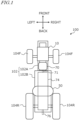
- FIG. 1 is a plan view schematically showing an example of the basic configuration of a work vehicle 100 according to the present disclosure.
- the direction in which the work vehicle 100 travels straight forward is referred to as the "forward direction”
- the direction in which it travels straight backward is referred to as the "backward direction”.
- the direction extending perpendicularly to the right of the "forward direction” is referred to as the "right direction”
- the direction extending perpendicularly to the left is referred to as the "left direction”.
- the "forward direction”, “backward direction”, “right direction”, and “left direction” are indicated by arrows labeled "front”, “back”, “right”, and “left” respectively. Both the forward and backward directions may be collectively referred to as the "front-back direction”.
- the work vehicle 100 like a conventional tractor, includes a vehicle frame 102 that rotatably supports left and right front wheels 104F and left and right rear wheels 104R.
- the vehicle frame 102 includes a front frame 102A, where the front wheels 104F are mounted, and a transmission case 102B, where the rear wheels 104R are mounted.
- the front frame 102A is fixed to the front portion of the transmission case 102B.
- the front wheels 104F and rear wheels 104R may be collectively referred to as wheels 104.
- the wheels 104 refer to wheel rims with tires attached.
- the term "wheel” generally refers to the entire assembly of the "wheel rim and tire”.
- Either or both of the front wheels 104F and rear wheels 104R may be replaced with a plurality of wheels (crawlers) fitted with endless tracks instead of wheeled tires.
- the work vehicle 100 includes a fuel cell module (FC module) 10 and a motor 70, which are directly or indirectly supported by the front frame 102A.
- FC module 10 includes a fuel cell stack (FC stack) and functions as an onboard power generator that generates electricity from fuel, as will be described later.
- FC stack fuel cell stack
- the motor 70 is electrically connected to the FC module 10.
- the motor 70 converts the electric power generated by the FC module 10 into mechanical motion (power) to produce the driving force (traction) necessary for the work vehicle 100 to travel.
- An example of the motor 70 is an AC synchronous motor. Since the FC stack of the FC module 10 generates direct current, when the motor 70 is an AC synchronous motor, a group of electrical circuits, including an inverter device, is installed between the FC stack and the motor 70 to convert the direct current to alternating current. A portion of such electrical circuit group may be inside the FC module 10, while another portion of the electrical circuit group may be attached to the motor 70 as a motor drive circuit.
- a power take-off (PTO) shaft 76 is provided at the rear end of the transmission case 102B.
- the PTO shaft 76 is driven by the motor 70 and implements is configured to be connected to.
- the torque from the output shaft 71 of the motor 70 is transmitted to the PTO shaft 76.
- Implements attached to or towed by the work vehicle 100 are configured to receive power from the PTO shaft 76 to perform various work-related operations.
- the motor 70 and the power transmission system 74 may collectively be referred to as an electric powertrain.
- the work vehicle 100 disclosed herein does not include an internal combustion engine such as a diesel engine, but includes the FC module 10 and the motor 70. Additionally, the output shaft 71 of the motor 70 is mechanically coupled to the power transmission system 74, including the transmission in the transmission case 102B.
- the motor 70 efficiently generates torque over a relatively wide range of rotational speeds compared to an internal combustion engine.
- the power transmission system 74, including the transmission it becomes easier to adjust the torque and rotational speed from the motor 70 over an even wider range by performing multi-stage or continuously variable speed change operations. This configuration allows for efficient execution of not only the travel of the work vehicle 100 but also various operations using implements.
- some functions of the power transmission system 74 may be omitted. For example, a portion or an entirety of the transmission responsible for speed change functions may be omitted.
- the number and mounting position of motors 70 are also not limited to the example shown in FIG. 1 .
- the work vehicle 100 includes at least one fuel tank 50 that stores fuel to be supplied to the FC module 10.
- FIG. 1 shows one fuel tank 50.
- a plurality of fuel tanks 50 may be housed in a tank case to define a fuel tank module.
- the fuel tank 50 is supported by structural elements fixed to the vehicle frame 102A described later.
- the FC module 10 and the fuel tank 50 are connected by piping and open/close valves, and similar components, defining an FC power generation system mounted on a vehicle. The configuration and operation of the FC power generation system will be described later.
- FC power generation system 180 mounted on the work vehicle 100 .
- the FC power generation system 180 shown in FIG. 2 functions as an onboard power generation system in the work vehicle 100 of FIG. 1 .
- the electric power generated by the FC power generation system 180 is used not only for the travel of the work vehicle 100 but also for the operation of implements towed or attached to the work vehicle 100.
- FIG. 2 shows a coolant circulation system including a coolant pump 31 for the FC stack 11, but as described later, cooling circulation systems for other electrical equipment may also be provided. Note that the air compressor 12, fuel circulation pump 24, and coolant pump 31 included in the FC module 10 are driven by individual built-in motors. These motors are also electrical equipment.
- the coolant pump 31 is provided on either the coolant supply pipe 32 or the coolant discharge pipe 33 to pump coolant to the FC stack 11.
- a coolant bypass flow path may be provided between the coolant discharge pipe 33 and the coolant supply pipe 32.
- a flow dividing valve is provided at the branching point at which the coolant bypass flow path branches from the coolant discharge pipe 33. The flow dividing valve is configured to adjust the flow rate of coolant flowing through the bypass flow path.
- the temperature sensor S3 detects the temperature of the coolant flowing through the coolant discharge pipe 33.
- the coolant used to cool the FC stack 11 is circulated through the flow path by an electric coolant pump 31.
- a coolant control valve may be provided downstream of the FC stack 11.
- the coolant control valve adjusts the ratio of coolant flowing to the radiator device 34 and coolant bypassing the radiator device 34, enabling more accurate control of the coolant temperature.
- the liquid delivery amount by the coolant pump it is also possible to control the coolant temperature difference between the inlet and outlet of the FC stack 11 to be within a desired range.
- the temperature of the coolant in the FC stack 11 may be controlled to be around 70°C, for example, which is a temperature where the power generation efficiency of the FC stack 11 is high.
- Electrical connections include both high-voltage and low-voltage systems.
- High-voltage electrical connections provide, for example, the power supply voltage for inverter devices.
- Low-voltage electrical connections provide, for example, the power supply voltage for electronic components that operate at relatively low voltages.
- the torque of the output shaft 71 of the motor 70 is transmitted to the power transmission system 74.
- the power transmission system 74 operates with the motor 70 as the power source and drives the wheels 104R and 104F, and/or the PTO shaft 76 shown in FIG. 1 .
- This power transmission system 74 may have the same or similar structure as the power transmission system in conventional tractors including internal combustion engines such as diesel engines.
- a power transmission system used in agricultural tractors for example, it is possible to reduce the design and manufacturing costs for producing an agricultural work vehicle 100 including an FC power generation system.
- the power transmission system 74 includes a travel power transmission mechanism that transmits power from the motor 70 to the left and right rear wheels 104R through a clutch, transmission, and rear wheel differential device, and a PTO power transmission mechanism that transmits power from the motor 70 to the PTO shaft 76.
- the power transmission system 74 includes a PTO clutch that switches between a state (connected state) in which power from the motor 70 is transmitted to the PTO shaft 76 and a state (disconnected state) in which it is not transmitted.
- the PTO clutch may be manually operated by the driver through the operation of an operating portion such as a clutch pedal.
- the PTO clutch may also be automatically disconnected by control or other means.
- the transmission case 102B in FIG. 1 may be divided into a front case (mission case) housing clutches such as the PTO clutch and transmission, and a rear case (differential gear case) housing the rear wheel differential device.
- the rear case may also be referred to as a rear axle case.
- the work vehicle 100 shown in FIG. 3 includes a temperature control device that cools or heats the FC stack 11 included in the FC power generation system.
- the operation of the temperature control device or alike requires relatively large power.
- the relatively high 24-volt voltage output by the second DC-DC converter 82 is applied to the temperature control device.
- the temperature control device includes the radiator device 34 that releases heat from the coolant cooling the FC stack 11, and the relatively high 24-volt voltage (second voltage) output by the second DC-DC converter 82 is applied to the radiator device 34.
- the temperature control device includes a heater 86 that heats the FC stack 11.
- the relatively high voltage output by the second DC-DC converter 82 may also be applied to the heater.
- the relatively high voltage output by the second DC-DC converter 82 may also be applied to air conditioning devices such as the air conditioning compressor 85.
- the work vehicle 100 may include a third voltage conversion circuit that converts the high voltage output by the FC module 10 to a third voltage higher than the second voltage.
- the third voltage is, for example, 48 volts. If the work vehicle 100 includes another motor in addition to the motor 70, for example, the third voltage may be used as the power source for such other motors.
- the agricultural work vehicle in addition to the electrical equipment necessary for agricultural task, the agricultural work vehicle also includes electrical equipment necessary for the operation of fuel cell power generation, so the appropriate voltage magnitude may differ for each electrical equipment. According to the embodiments of this disclosure, it is possible to supply voltages of appropriate magnitudes.
- a plurality of fuel tanks 50 are housed in a single tank case 51.
- the fuel tank 50 is connected to a supplying port (fueling port) 52 through which fuel is supplied from the outside. This connection is made via piping 21 to flow fuel gas.
- the fuel tank 50 is also connected to the FC module 10 via piping 21, which is equipped with an open/close valve 20.
- the piping 21 may be formed from materials with high resistance to hydrogen embrittlement, such as austenitic stainless steel like SUS316L.
- a valve space 53 is provided in the tank case 51, and various valves including a pressure reducing valve are placed in the valve space 53.
- the piping 21 connects the fuel tank 50 and the FC module 10.
- Fuel gas with reduced pressure by the pressure reducing valve flows through the piping 21 connecting the tank case 51 and the FC module 10.
- the fuel gas is hydrogen gas
- high-pressure hydrogen gas of, for example, 35 megapascals or more may be filled in the fuel tank 50, but the hydrogen gas after passing through the pressure reducing valve may be reduced to about 2 atmospheres or less.
- the fuel tank 50 is equipped with a sensor S4 to measure the remaining amount of fuel in the fuel tank 50. Additionally, a temperature sensor may be provided to measure the temperature inside the fuel tank 50. Examples of sensor S4 include a pressure sensor that measures the pressure of the fuel corresponding to the remaining amount of fuel. The pressure sensor acquires residual pressure data indicating the residual pressure of the fuel remaining in the fuel tank 50.
- the first and second DC-DC converters 81 and 82 are configured to output voltages of different magnitudes. ECUs are also provided for these first and second DC-DC converters 81 and 82 to control each voltage conversion circuit. The relatively low first voltage which the first DC-DC converter 81 outputs is applied to these ECUs, like other ECUs.
- the work vehicle 100 includes a cooling system in which coolant circulates via coolant pumps 31A and 31B. These coolant pumps 31A and 31B are provided inside the FC module 10.
- the cooling system in this example includes a first radiator device 34A responsible for cooling the FC stack 11 and a second radiator device 34B to cool other electrical equipment.
- the cooling system includes a flow path (first flow path) where coolant flows between the FC stack 11 and the first radiator device 34A.
- this cooling system has a flow path (second flow path) where coolant flows between electrical equipment including the motor 70 and the second radiator device 34B.
- a heater core 87 used to heat the cabin is provided, and the coolant flowing through the first radiator device 34A flows through the heater core 87.
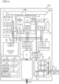
- the user interface 1 includes an operation device 2 such as an accelerator pedal (or accelerator lever) and a main ECU 3 connected to the operation device 2.
- the main ECU 3 is connected to a main meter 4.
- the main meter 4 may display various parameters that identify the travel state or operating state of the work vehicle 100.
- the user interface 1 further includes an FC system ECU 5 configured or programmed to control the FC power generation system.
- the FC system ECU 5 is connected to an FC meter 6.
- the FC meter 6 may display various parameters that identify the operating state of the FC power generation system.
- the user interface 1 includes an operation device 2 such as an accelerator pedal (or accelerator lever) and a main ECU 3 connected to the operation device 2.
- the main ECU 3 is connected to a main meter 4, a storage device 7, an audio output device 8, and other components.
- the main meter 4 may display various parameters that identify the travel state or operating state of the work vehicle 100.
- the user interface 1 further includes an FC system ECU 5 to control the FC power generation system.
- the FC system ECU 5 is connected to an FC meter 6.
- the FC meter 6 may display various parameters that identify the operating state of the FC power generation system.
- the cells of the battery pack 80 are controlled by a Battery Management Unit (BMU).
- BMU Battery Management Unit
- the BMU includes circuits and a CPU (Central Processing Unit) that perform voltage monitoring for each cell of the battery, monitoring of overcharging and overdischarging, and cell balance control. These circuits and CPU may be mounted on a battery controller board.
- CPU Central Processing Unit
- the operation terminal 400 is a terminal for the user to execute operations related to the travel of the work vehicle and the operation of the implement, and is also referred to as a virtual terminal (VT).
- the operation terminal 400 may include a touch screen type display device and/or one or more buttons.
- the display device may be, for example, a display such as a liquid crystal or organic light-emitting diode (OLED).
- OLED organic light-emitting diode
- the operation terminal 400 may be configured to be detachable from the work vehicle 200. A user at a location away from the work vehicle 200 may operate the detached operation terminal 400 to control the operation of the work vehicle 200.
- the input device 410 is a device to convert instructions from the user into data and to input it into the computer.
- the display device 420 may be, for example, a liquid crystal display or an organic EL display.
- the display device 420 includes a touch screen and, in addition to the function of displaying images, also serves as the input device 410.
- the RAM 450 provides a work area for temporarily expanding the control program stored in the ROM 440 at boot time.
- the RAM 450 does not need to be a single storage medium, but may be an aggregate of a plurality of storage media.
- the storage device 460 may be, for example, a magnetic storage device or a semiconductor storage device.
- An example of a magnetic storage device is a hard disk drive (HDD).
- An example of a semiconductor storage device is a solid-state drive (SSD).
- the communication device 470 is a communication module to communicate, for example, with a cloud server that manages agricultural work, a work vehicle, or a terminal device that may be used by a user (such as a farm manager or agricultural worker) via a network.
- the communication device 470 can perform wired communication compliant with communication standards such as IEEE1394 (registered trademark) or Ethernet (registered trademark), for example.
- the communication device 470 may perform wireless communication compliant with Bluetooth (registered trademark) or Wi-Fi standards, or cellular mobile communication such as 3G, 4G, or 5G.
- the work vehicle 200 may further include at least one sensing device that senses the environment around the work vehicle 200, and a processor that processes sensor data output from the at least one sensing device.
- the sensing device may include, for example, a plurality of cameras, a LiDAR sensor, and a plurality of obstacle sensors.
- the sensor data output from the sensing device may be used for positioning, for example.
- Various ECUs mounted on the work vehicle 200 may collaborate to perform calculations and control for realizing autonomous driving based on the sensor data output from the sensing device.
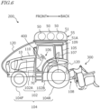
- the fuel tank 50 is supported by a mounting frame 120.
- the mounting frame 120 is fixed to the vehicle frame 102 straddling the driver seat 107.
- the fuel tank 50 is located above the driver seat 107.
- the installation location of the fuel tank 50 is not limited to the illustrated example and may be, for example, inside the front housing 110.
- the mounting frame 120 is an elongated structure such as a pipe fixed to the vehicle frame 102.
- the mounting frame 120 includes two frames positioned on the left and right sides of the work vehicle 200 (refer to FIG. 5 ).
- the front portion of the mounting frame 120 has a curved shape. Note that the shape of the mounting frame 120 shown is just an example, and the shape of the mounting frame 120 is not limited to this example.
- the vehicle frame 102 includes a front frame 102A that rotatably supports the front wheels 104F, and a transmission case 102B that rotatably supports the rear wheels 104R.
- One end (front end) of the mounting frame 120 is fixed to the front frame 102A.
- the other end (rear end) of the mounting frame 120 is fixed to the transmission case 102B.
- fixations may be made by appropriate methods such as welding or bolt joining, depending on the material of the mounting frame 120.
- the mounting frame 120 may be formed from metal, synthetic resin, carbon fiber, or composite materials such as carbon fiber reinforced plastic or glass fiber reinforced plastic.
- the transmission case 102B includes a rear axle case, and the rear end of the mounting frame 120 may be fixed to the rear axle case. When the mounting frame 120 is formed from metal, a portion or entirety of its surface may be covered with synthetic resin.
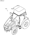
- the work vehicle 200 includes a cabin 105 that surrounds the driver seat 107 between the vehicle frame 102 and the mounting frame 120.
- the driver seat 107 is located in the rear portion of the interior of the cabin 105.
- a steering wheel 106 for changing the direction of the front wheels 104F, and an operation terminal 400 are provided in front of the driver seat 107.
- the cabin 105 includes a cabin frame that forms its skeleton.
- a roof 109 is provided on the upper part of the cabin frame.
- the cabin frame in this embodiment is a 4-pillar style.
- the cabin 105 is supported by the transmission case 102B of the vehicle frame 102, for example, via vibration-isolating mounts.
- the user interface 1 explained with reference to FIG. 4 is provided inside the cabin 105. Since the cabin 105 does not directly support the fuel tank 50, there is no need to specially increase its strength, and a cabin that has been used in conventional tractors can be adopted.
- the work vehicle 200 includes a placement platform 51A that connects the left frame 120 and the right frame 120.
- the fuel tank 50 may be placed on the placement platform 51A.
- the plurality of fuel tanks 50 may be provided in a fuel tank module 55.
- the fuel tank module 55 includes a tank case 51 that houses a plurality of fuel tanks 50.
- the left and right mounting frames 120 may be connected to each other by structural elements other than the placement platform 51A.
- a coupling device 108 is provided at the rear end of the transmission case 102B, which is the rear portion of the vehicle frame 102.
- the coupling device 108 includes, for example, a three-point support device (also referred to as a "three-point link” or “three-point hitch”), a PTO shaft, a universal joint, and a communication cable.
- the implement 300 may be attached to or detached from the work vehicle 200 using the coupling device 108.
- the coupling device 108 can, for example, raise and lower the three-point link by a hydraulic device to change the position or posture of the implement 300.
- power can be transmitted from the work vehicle 200 to the implement 300 via the universal joint.
- the work vehicle 200 can execute predetermined work (agricultural task) with the implement 300 while pulling the implement 300.
- the coupling device 108 may be provided on the front portion of the vehicle frame 102. In that case, the implement 300 can be connected to the front of the work vehicle 200.
- the implement 300 includes, for example, a drive device, a control device, and a communication device.
- the drive device performs the necessary actions for the implement 300 to execute predetermined work.
- the drive device includes, for example, a hydraulic device, an electric motor, or a pump, depending on the application of the implement 300.
- the control device controls the operation of the drive device.
- the control device executes various operations of the drive device in response to signals transmitted from the work vehicle 200 via the communication device. It is also possible to transmit signals corresponding to the state of the implement 300 to the work vehicle 200 from the communication device.
- the implement 300 shown in FIG. 6 is a rotary tiller, but the implement 300 is not limited to a rotary tiller.
- any implement such as a seeder, a spreader (fertilizer applicator), a transplanter, a mower, a rake, a baler, a harvester, a sprayer, or a harrow can be connected to and used with the work vehicle 200.
- the work vehicle 200 shown in FIG. 6 is capable of manned operation, but it may also be adapted for unmanned operation only. In that case, components necessary only for manned operation, such as the cabin 105, steering wheel 106, and driver seat 107, may not be provided on the work vehicle 200.
- the work vehicle 200 which is unmanned can travel by autonomous driving or remote control by the user.
- the types of implements are, as described above, for example, rotary, seeder, or spreader.
- the types of work performed by the implement are, for example, tilling, seeding, or fertilizing. Note that the type of implement and the type of work do not necessarily correspond one-to-one.
- the type of implement when the type of implement is a rotary, the type of work may include a plurality of types such as tilling, puddling, or ridging.
- the processing device acquires identification information of the implement 300 from the implement 300 connected to the PTO shaft 76, and identifies the type of implement 300 based on the identification information.
- the work vehicle 200 and the implement 300 are configured to communicate in compliance with ISOBUS standards such as ISOBUS-TIM. In this manner, the processing device of the work vehicle 200 may obtain the identification information of the implement 300 by communicating with the implement 300.
- the processing device may identify the type of implement 300 connected to the PTO shaft 76 and/or the type of work performed by the implement 300 based on information about the type of implement 300 and/or the type of work input by the user, for example, via the input device 410 of the operation terminal 400.
- the sensor S4 obtains residual data of the fuel in the fuel tank 50.
- the processing device is configured to estimate the remaining amount of fuel based on the residual pressure data output from the sensor S4.
- the remaining amount of fuel estimated in this manner may be referred to as the remaining amount of fuel measured by the sensor S4.
- the remaining amount of fuel may be expressed as a percentage (%) of the remaining amount relative to the tank capacity in a full state.
- the storage device 7 shown in FIG. 4 stores data indicating the relationship between the type of implement and/or the type of work, and the fuel consumption per unit time.
- the processing device in this embodiment estimates at least one of the travelable distance, travelable area, and travelable time with work based on this data.
- the unit of fuel consumption per unit time is, for example, L/h (liters/hour).
- the fuel consumption per unit time is simply referred to as "fuel consumption”.
- FIG. 8 is a diagram showing an example of a table showing the relationship between the type of implement, the type of work, and fuel consumption.
- the types of implements include five types: rotary, spreader, seeder, mower, and harrow
- the types of work include seven types: tilling, puddling, ridging, fertilizing, seeding, mowing, and pulverizing.
- the table lists the corresponding fuel consumption for each combination of implement type and work type. For example, the fuel consumption when the work vehicle 200 is performing tilling work while towing a rotary is C1 L/h, and the fuel consumption when the work vehicle 200 is performing fertilizing work while towing a spreader is C4 L/h.
- the fuel consumption may differ depending on the type of implement. Additionally, even when the type of implement is the same, the fuel consumption may differ depending on the type of work.
- the fuel consumption included in the example table means the combined fuel consumption of the work vehicle and the implement.
- the storage device may store table data that individually associates the fuel consumption of the work vehicle and the fuel consumption of the implement with the type of implement and the type of work.
- the processing device simply adds up the respective fuel consumptions identified by referring to the table.
- the storage device 7 may store the fuel consumption C9 (L/h) when the implement 300 is not driven, that is, when the PTO is not driven.
- the processing device may estimate the travelable time and distance (e.g., km) without work based on the fuel consumption C9 (L/h) and the remaining amount of fuel (L) measured by the sensor S4. It should be noted that the fuel consumption C9 (L/h) when the implement is not driven is smaller than the fuel consumption when the implement is driven (for example, any of C1 to C8 shown in FIG. 8 ).
- FIG. 9A is a diagram schematically showing an example of displaying estimation results on the display device when the implement is driven.
- FIG. 9B is a diagram schematically showing an example of displaying estimation results on the display device when the implement is not driven.
- the display devices exemplified in FIG. 9A and FIG. 9B are the main meter 4 and the FC meter 6.
- each of the main meter 4 and the FC meter 6 is a digital meter.
- a digital meter is not essential.
- the display of the main meter 4 includes, for example, information related to the speed of the work vehicle 200, time, fuel consumption, turn signal indicator, parking brake lamp, charge lamp indicating abnormality in the charging system, and water temperature gauge indicator showing the state of the radiator device (e.g., temperature measured by the temperature sensor S3 ).
- FC meters 6 are placed on both sides of the main meter 4.
- the FC meter 6 may be placed only on one side of the main meter 4, and the shape of each meter is not limited to the illustrated example and can be arbitrary.
- the FC meter 6 displays information related to the operating state of the FC power generation system 180. In this embodiment, the FC meter 6 further displays the estimation results of the processing device described above as prediction information.
- the display of the FC meter 6 on the left side in the examples shown in FIG. 9A and FIG. 9B includes information related to the battery SOC (state of charge) indicating the charging state of the battery pack 80, the remaining amount of fuel (%) in the fuel tank 50, the temperature of the fuel tank (°C), and the value (kPa) of the sensor S4 (pressure sensor) provided in the fuel tank 50.
- the display of the FC meter 6 on the left side further includes the power generation state of the FC stack 11, a warning lamp 9 to warn abnormalities in the fuel tank 50, and indicators corresponding to the battery SOC and the remaining amount of fuel, respectively.
- the FC meter 6 on the right side displays information on the travelable distance and travelable time, which are the estimation results when the implement is not driven.
- a prediction button operation button
- the display of the FC meter 6 on the right side may be configured to switch from the state shown in FIG. 9A to the state shown in FIG. 9B .
- the prediction button is a button to cause the processing device to execute estimation based on the fuel consumption C9.
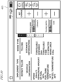
- FIG. 10 is a diagram schematically showing another example of displaying estimation results on the display device.
- the display device exemplified in FIG. 10 is an operation terminal 400.
- the screen of the operation terminal 400 may also display the same or similar information as that which may be displayed on the FC meter 6.
- the screen of the operation terminal 400 exemplified in FIG. 10 displays an input interface to set vehicle speed and plowing depth, and vehicle information, in addition to the type of implement, the type of work, and prediction information.
- the processing device may calculate at least one of a travelable distance, a travelable area, and a travelable time when the operation of the implement 300 is stopped, and display the calculation results on the display device. Compared to operating the implement, stopping the operation of the implement may improve fuel consumption. Therefore, the travelable distance and workable area may expand, and the travelable time may become longer.
- the processing device may estimate at least one of the travelable distance, travelable area, and travelable time based on the fuel consumption or fuel efficiency of the work vehicle 200 and the remaining amount of fuel. This allows, for example, the driver to easily make decisions about stopping the operation of the implement, as they can grasp the prediction information when the operation of the implement is stopped.
- FIG. 11 is a diagram schematically showing an example of a display including information prompting refueling.
- FIG. 11 shows an example of a digital meter display.
- the processing device may display information prompting refueling on the display device when the remaining amount of fuel falls below a threshold value.
- the threshold value may be set to, for example, 10-20%.
- the processing device may display (pop up) a message 401 such as "Refueling is necessary" on the FC meter 6 as shown in FIG. 11 .
- a display can easily prompt, for example, the driver to refuel.
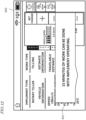
- FIG. 12 is a diagram schematically showing an example of a pop-up display including information on travelable time.
- FIG. 12 shows an example of a display on the screen of the operation terminal 400.
- the processing device may display a pop-up display including prediction information based on the estimation results on the display device.
- the processing device may display (pop up) a message 401 such as "You can work for 15 more minutes with the implement in operation" on the FC meter 6.
- the message is not limited to the illustrated example, and may be, for example, a message notifying that the remaining amount of fuel is low, a message prompting the replacement of the cartridge of the ion exchanger included in the FC module, or a message prompting to stop in case the implement is detached.
- FIG. 13 is a diagram schematically showing an example of a display including map information.
- the map in the example of the display shown in FIG. 13 includes a target route indicated by arrows set within the field.
- the work vehicle 200 may further include a GNSS (Global Navigation Satellite System) receiver used for positioning.
- GNSS Global Navigation Satellite System
- the main ECU 3 of the work vehicle 200 may automatically travel the work vehicle 200 based on the position of the work vehicle 200 and the information of the target route.
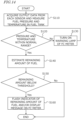
- FIG. 14 is a flowchart showing the processing procedure of an example operation of the processing device.
- the processing device acquires sensor data output from the temperature sensor of the fuel tank 50 and measures the temperature of the fuel tank 50 based on the sensor data.
- the processing device acquires sensor data output from the sensor S4 (pressure sensor) of the fuel tank 50 and measures the pressure of the fuel in the fuel tank 50 based on the sensor data (step S110 ).
- the processing device estimates the remaining amount of fuel based on the fuel pressure as described above (S140).
- the processing device determines whether the remaining amount of fuel is less than a threshold value (S150).
- the processing device may, for example, flash the fuel remaining indicator of the FC meter 6 or display a message prompting refueling on the FC meter 6 (S160).
- the processing device may display the aforementioned travelable distance, time, or workable area on the FC meter 6.
- the present disclosure includes work vehicles as recited in the following Items.
Landscapes
- Engineering & Computer Science (AREA)
- Mechanical Engineering (AREA)
- Transportation (AREA)
- Power Engineering (AREA)
- Life Sciences & Earth Sciences (AREA)
- Sustainable Development (AREA)
- Sustainable Energy (AREA)
- Combustion & Propulsion (AREA)
- Chemical & Material Sciences (AREA)
- Physics & Mathematics (AREA)
- General Physics & Mathematics (AREA)
- Acoustics & Sound (AREA)
- Soil Sciences (AREA)
- Environmental Sciences (AREA)
- Electric Propulsion And Braking For Vehicles (AREA)
- Cooling, Air Intake And Gas Exhaust, And Fuel Tank Arrangements In Propulsion Units (AREA)
Abstract
Description
- The present disclosure relates to work vehicles.
- In the field of motor vehicles, where the main purpose is to transport "people" or "objects", electric vehicles (EVs) are becoming increasingly popular. In these vehicles, the driving force (traction) is generated by an electric motor (hereinafter referred to as "motor") instead of an internal combustion engine.
- On the other hand, there is a need to reduce the amount of carbon dioxide (CO2) emitted by work vehicles, such as tractors used in agricultural fields, to realize a decarbonized society. Unlike typical automobiles, work vehicles such as tractors need to tow implements, which are work machines, to perform agricultural tasks such as plowing. Therefore, to achieve the electrification of work vehicles, there are issues to be solved that differ from those of passenger cars.
-
Patent Document 1 discloses a vehicle including a fuel cell, a battery, a drive device to convert power generated by the fuel cell and battery into motive power, and a display device to display an indicator showing the power output from the fuel cell and battery. The display device displays information on the indicator showing a threshold used to determine whether to supply power to the drive device from either the fuel cell or battery, or from both the fuel cell and battery. - [Patent Document 1]
Japanese Laid-Open Patent Publication No. 2021-123177 - The present disclosure provides technology for improving the convenience of a work vehicle equipped with a fuel cell module.
- A work vehicle according to one aspect of the present disclosure includes: a fuel cell module including a fuel cell stack; at least one fuel tank to store fuel to be supplied to the fuel cell stack; a sensor to measure a remaining amount of fuel in the fuel tank; a motor connected to the fuel cell module; a power take-off shaft to be driven by the motor and to which an implement is connected; a display device; and a processing device to estimate, based on the measured remaining amount of fuel and a type of the implement connected to the power take-off shaft and/or a type of work performed by the implement, at least one of a travelable distance, a travelable area, or a travelable time with the work , and to display an estimation result on the display device.
- Comprehensive or specific aspects of the present disclosure may be achieved by apparatuses, systems, methods, integrated circuits, computer programs, or computer-readable nontransitory storage media, or any combination thereof. The computer-readable storage media may include volatile storage media or non-volatile storage media. The apparatuses may be configured with a plurality of devices. When the apparatuses are configured with two or more devices, the two or more devices may be arranged within a single equipment or may be arranged separately in two or more pieces of equipment.
- According to embodiments of the present disclosure, it becomes possible to improve the convenience of a work vehicle equipped with a fuel cell module.
-
- [
Fig. 1 ] A plan view schematically showing a basic configuration example of a work vehicle according to the present disclosure. - [
Fig. 2 ] A diagram showing a basic configuration example of a fuel cell power generation system mounted on the work vehicle. - [
Fig. 3 ] A block diagram schematically showing an example of electrical connections and power transmission between components of the work vehicle according to the present disclosure. - [
Fig. 4 ] A block diagram schematically showing paths of electrical signals (solid thin lines) and coolant paths (dotted lines) between components of a work vehicle according to the present disclosure. - [
Fig. 5 ] A perspective view schematically showing a configuration example of a work vehicle according to an embodiment of the present disclosure. - [
Fig. 6 ] A side view schematically showing a configuration example of a work vehicle according to an embodiment of the present disclosure. - [
Fig. 7 ] A block diagram showing an example hardware configuration of an operation terminal. - [
Fig. 8 ] A diagram showing an example of a table indicating the relationship between implement types, work types, and fuel consumption. - [
Fig. 9A ] A diagram schematically showing an example of displaying estimation results on the display device when driving an implement. - [
Fig. 9B ] A diagram schematically showing an example of displaying estimation results on the display device when not driving an implement. - [
Fig. 10 ] A diagram schematically showing another example of displaying estimation results on the display device. - [
Fig. 11 ] A diagram schematically showing an example of a display including information prompting fuel replenishment. - [
Fig. 12 ] A diagram schematically showing an example of a popup display including information on travelable time. - [
Fig. 13 ] A diagram schematically showing an example of a display including map information. - [
Fig. 14 ] A flowchart showing an example of the processing procedure for the operation of the processing device. - The following describes embodiments of the present disclosure. However, excessively detailed explanations may be omitted. For example, detailed explanations of well-known matters and repetitive explanations of substantially identical configurations may be omitted. This is to avoid the following description from becoming unnecessarily redundant and to facilitate understanding by those skilled in the art. The inventors provide the attached drawings and the following description to enable those skilled in the art to fully understand this disclosure, and do not intend to limit the subject matter described in the claims by these drawing and description. In the following description, the same reference numerals are used for components with the same or similar functions.
- The following embodiments are illustrative and not limiting. The technologies disclosed herein are not restricted to the following embodiments. For instance, the numerical values, shapes, materials, steps, the order of those steps, screen layouts, and other elements shown in the following embodiments are merely examples. Various modifications can be made as long as no technical contradictions arise. Additionally, different features, elements, characteristics, etc., of the example embodiments may be combined as long as there are no technical contradictions.
- In this disclosure, the term "work vehicle" refers to a vehicle used to perform a task at a work site. A "work site" includes any place where work is carried out, such as a field, forest, or construction site. A "field" refers to any place where agricultural work is performed, such as an orchard, farm, paddy field, grain farm, or pasture. A work vehicle may include an agricultural machine such as a tractor, rice planter, combine harvester, riding field management vehicle, or riding mower, as well as a non-agricultural vehicle such as a construction work vehicle or snowplow. The work vehicles described in this disclosure may be equipped with an implement (also called a "work machine" or "work device") attached to at least one of its front and rear portions, depending on the nature of the work. Travel of a work vehicle while performing a task may be referred to as "tasked travel".
- An "agricultural machine" refers to a machine for agricultural application. Examples of agricultural machines include tractors, harvesters, rice planters, riding field management vehicles, vegetable transplanters, mowers, seeders, spreaders, and agricultural mobile robots. Not only may a work vehicle such as a tractor function as an "agricultural machine" on its own, but also the entire combination of a work vehicle and an implement attached to or towed by the work vehicle may function as an "agricultural machine". An agricultural machine performs agricultural work on the ground in a field, such as tilling, seeding, pest control, fertilizing, planting crops, or harvesting.
- An example of the basic configuration and operation of the work vehicle according to this disclosure will be described. The work vehicle described below includes a motor and a fuel cell power generation system (hereinafter referred to as "FC power generation system") that is configured to generate the power necessary to drive the motor.
-
FIG. 1 is a plan view schematically showing an example of the basic configuration of awork vehicle 100 according to the present disclosure. In this disclosure, the direction in which thework vehicle 100 travels straight forward is referred to as the "forward direction", and the direction in which it travels straight backward is referred to as the "backward direction". In a plane parallel to the ground, the direction extending perpendicularly to the right of the "forward direction" is referred to as the "right direction", and the direction extending perpendicularly to the left is referred to as the "left direction". InFIG. 1 , the "forward direction", "backward direction", "right direction", and "left direction" are indicated by arrows labeled "front", "back", "right", and "left" respectively. Both the forward and backward directions may be collectively referred to as the "front-back direction". - The
work vehicle 100 illustrated in this example is, for instance, a tractor, which defines and functions as an example of agricultural machinery. The technologies disclosed herein are not limited to work vehicles such as tractors and may be applied to other types of work vehicles. Thework vehicle 100 is configured to attach or tow an implement and travel within a field while performing agricultural tasks appropriate to the type of implement. Additionally, thework vehicle 100 is configured to travel both within and outside the field (including on roads) with the implement raised or without an implement attached. - The
work vehicle 100, like a conventional tractor, includes avehicle frame 102 that rotatably supports left and rightfront wheels 104F and left and rightrear wheels 104R. Thevehicle frame 102 includes afront frame 102A, where thefront wheels 104F are mounted, and atransmission case 102B, where therear wheels 104R are mounted. Thefront frame 102A is fixed to the front portion of thetransmission case 102B. Thefront wheels 104F andrear wheels 104R may be collectively referred to aswheels 104. Strictly speaking, thewheels 104 refer to wheel rims with tires attached. In this disclosure, the term "wheel" generally refers to the entire assembly of the "wheel rim and tire". Either or both of thefront wheels 104F andrear wheels 104R may be replaced with a plurality of wheels (crawlers) fitted with endless tracks instead of wheeled tires. - In the example shown in
FIG. 1 , thework vehicle 100 includes a fuel cell module (FC module) 10 and amotor 70, which are directly or indirectly supported by thefront frame 102A. TheFC module 10 includes a fuel cell stack (FC stack) and functions as an onboard power generator that generates electricity from fuel, as will be described later. Hereinafter, the terms "FC module" or "FC stack" may simply be referred to as "fuel cell". - The
motor 70 is electrically connected to theFC module 10. Themotor 70 converts the electric power generated by theFC module 10 into mechanical motion (power) to produce the driving force (traction) necessary for thework vehicle 100 to travel. An example of themotor 70 is an AC synchronous motor. Since the FC stack of theFC module 10 generates direct current, when themotor 70 is an AC synchronous motor, a group of electrical circuits, including an inverter device, is installed between the FC stack and themotor 70 to convert the direct current to alternating current. A portion of such electrical circuit group may be inside theFC module 10, while another portion of the electrical circuit group may be attached to themotor 70 as a motor drive circuit. - The
motor 70 includes anoutput shaft 71 that rotates. The torque of theoutput shaft 71 is transmitted to therear wheels 104R through mechanical components such as a transmission (gearbox) and a rear wheel differential gear device installed inside thetransmission case 102B. In other words, the power generated by themotor 70, which serves as the power source, is transmitted to therear wheels 104R through a power transmission system (drivetrain) 74 including the transmission installed in thetransmission case 102B. For this reason, the "transmission case" may also be referred to as a "mission case". In four-wheel drive mode, a portion of the power of themotor 70 is also transmitted to thefront wheels 104F. The power of themotor 70 may be used not only to drive thework vehicle 100 but also to operate implements. Specifically, a power take-off (PTO)shaft 76 is provided at the rear end of thetransmission case 102B. ThePTO shaft 76 is driven by themotor 70 and implements is configured to be connected to. The torque from theoutput shaft 71 of themotor 70 is transmitted to thePTO shaft 76. Implements attached to or towed by thework vehicle 100 are configured to receive power from thePTO shaft 76 to perform various work-related operations. Themotor 70 and thepower transmission system 74 may collectively be referred to as an electric powertrain. - Thus, the
work vehicle 100 disclosed herein does not include an internal combustion engine such as a diesel engine, but includes theFC module 10 and themotor 70. Additionally, theoutput shaft 71 of themotor 70 is mechanically coupled to thepower transmission system 74, including the transmission in thetransmission case 102B. Themotor 70 efficiently generates torque over a relatively wide range of rotational speeds compared to an internal combustion engine. However, by utilizing thepower transmission system 74, including the transmission, it becomes easier to adjust the torque and rotational speed from themotor 70 over an even wider range by performing multi-stage or continuously variable speed change operations. This configuration allows for efficient execution of not only the travel of thework vehicle 100 but also various operations using implements. - Depending on the application or size of the
work vehicle 100, some functions of thepower transmission system 74 may be omitted. For example, a portion or an entirety of the transmission responsible for speed change functions may be omitted. The number and mounting position ofmotors 70 are also not limited to the example shown inFIG. 1 . - The
work vehicle 100 includes at least onefuel tank 50 that stores fuel to be supplied to theFC module 10. For simplicity,FIG. 1 shows onefuel tank 50. In some embodiments, a plurality offuel tanks 50 may be housed in a tank case to define a fuel tank module. Thefuel tank 50 is supported by structural elements fixed to thevehicle frame 102A described later. TheFC module 10 and thefuel tank 50 are connected by piping and open/close valves, and similar components, defining an FC power generation system mounted on a vehicle. The configuration and operation of the FC power generation system will be described later. - The
work vehicle 100 in the embodiments described later includes a seat for a driver, hereinafter referred to as "a driver seat", supported by thevehicle frame 102. The driver seat may be enclosed by a cabin supported by thevehicle frame 102. In the embodiments described later, theFC module 10 is positioned in front of the driver seat, and thefuel tank 50 is positioned above the driver seat.Such FC module 10 andfuel tank 50 are housed in at least one "enclosure". The "enclosure" functions as a housing, for example, and plays a role in protecting theFC module 10 andfuel tank 50 from sunlight exposure and wind and rain. Additionally, such an enclosure is designed to control the spread of fuel gas into the atmosphere and to facilitate the detection of fuel gas when fuel gas leaks from theFC module 10 orfuel tank 50. - The
FC module 10 may be housed in a front housing called a "bonnet", for example. The front housing is a portion of the "enclosure". The front housing is supported by the front portion of the vehicle frame 102 (front frame 102A). Thefuel tank 50 is housed in a tank case, as mentioned earlier. The tank case is directly or indirectly supported by thevehicle frame 102. - Next, referring to
FIG. 2 , a basic configuration example of the FCpower generation system 180 mounted on thework vehicle 100 will be explained. - The FC
power generation system 180 shown inFIG. 2 functions as an onboard power generation system in thework vehicle 100 ofFIG. 1 . The electric power generated by the FCpower generation system 180 is used not only for the travel of thework vehicle 100 but also for the operation of implements towed or attached to thework vehicle 100. - The FC
power generation system 180 in the illustrated example includes theFC module 10 and at least onefuel tank 50 that stores fuel to be supplied to theFC module 10. The FCpower generation system 180 also includes aradiator device 34 for cooling theFC module 10. - The
FC module 10 includes main components such as a fuel cell stack (FC stack) 11, anair compressor 12, afuel circulation pump 24, acoolant pump 31, aboost circuit 40, and acontrol device 42. These components are housed within the casing of theFC module 10 and are connected to each other through electrical or fluid communication. - The
FC stack 11 generates electric power through an electrochemical reaction between the fuel, referred to as "anode gas" and the oxidizing gas, referred to as "cathode gas". In this example, theFC stack 11 is composed of polymer electrolyte fuel cells. TheFC stack 11 has a stack structure in which a plurality of single cells (fuel cell elements) are stacked. A single cell includes, for example, an electrolyte membrane formed from an ion exchange membrane, an anode electrode formed on one side of the electrolyte membrane, a cathode electrode formed on the other side of the electrolyte membrane, and a pair of separators sandwiching the anode electrode and cathode electrode on both sides. The voltage generated in a single cell is, for example, less than 1 volt. Therefore, in theFC stack 11, for instance, more than 300 single cells are connected in series to generate a voltage of several hundred volts. - Anode gas is supplied to the anode electrode of the
FC stack 11. The anode gas is called "fuel gas" or simply "fuel". In the embodiments of this disclosure, the anode gas (fuel) is hydrogen gas. Cathode gas is supplied to the cathode electrode. The cathode gas is an oxidizing gas such as air. The anode electrode is called the fuel electrode, and the cathode electrode is called the air electrode. - At the anode electrode, the electrochemical reaction shown in the following equation (1) occurs.
2H2 → 4H+ + 4e ... equation (1)
- At the cathode electrode, the electrochemical reaction shown in the following equation (2) occurs.
4H+ + 4e + O2 → 2H2O ... equation (2)
- Overall, the reaction shown in the following equation (3) occurs.
2H2 + O2 → 2H2O ... equation (3)
- The anode gas after being used in the above reaction is called "anode off-gas", and the cathode gas after being used in the reaction is called "cathode off-gas".
- The
air compressor 12 supplies air taken from the outside as cathode gas to the cathode electrode of theFC stack 11. The cathode gas supply system including theair compressor 12 includes a cathodegas supply pipe 13, a cathode off-gas pipe 14, and abypass pipe 15. The cathodegas supply pipe 13 flows cathode gas (air) supplied from theair compressor 12 to the cathode electrode of theFC stack 11. The cathode off-gas pipe 14 flows cathode off-gas discharged from theFC stack 11 to the outside air. Thebypass pipe 15 branches from the cathodegas supply pipe 13 downstream of theair compressor 12, bypasses theFC stack 11, and connects to the cathode off-gas pipe 14. Acontrol valve 16 is provided on thebypass pipe 15 to adjust the flow rate of cathode gas flowing through thebypass pipe 15. A shut-offvalve 17 is provided on the cathodegas supply pipe 13 to selectively block the inflow of cathode gas to theFC stack 11. Apressure regulating valve 18 is provided on the cathode off-gas pipe 14 to adjust the back pressure of the cathode gas. - The cathode gas supply system of the
FC module 10 includes a rotation speed detection sensor S1 that detects the rotation speed of theair compressor 12 and a gas flow rate detection sensor S2 that detects the flow rate of cathode gas flowing through the cathodegas supply pipe 13. Thecontrol valve 16, shut-offvalve 17, andpressure regulating valve 18 are, for example, electromagnetic valves. - The
fuel circulation pump 24 supplies fuel gas (anode gas) sent from thefuel tank 50 to the anode electrode of theFC stack 11. The anode gas supply system including thefuel circulation pump 24 includes an anodegas supply pipe 21, an anode off-gas pipe 22, and acirculation path 23. The anodegas supply pipe 21 flows anode gas supplied from thefuel tank 50 to the anode electrode of theFC stack 11. In the embodiments of this disclosure, thefuel tank 50 is a hydrogen tank that stores high-pressure hydrogen gas. - The anode off-
gas pipe 22 flows anode off-gas discharged from theFC stack 11. The anode off-gas is led through the anode off-gas pipe 22 to a gas-liquid separator 25 in which moisture is removed. The anode off-gas with moisture removed returns to the anodegas supply pipe 21 through thecirculation path 23 by thefuel circulation pump 24. The anode off-gas circulating through thecirculation path 23 can be discharged through the anode off-gas pipe 22 by opening anexhaust valve 26. Moisture accumulated in the gas-liquid separator 25 can be discharged through the anode off-gas pipe 22 by opening theexhaust valve 26. Theexhaust valve 26 is, for example, an electromagnetic valve. In the example shown in the figure, the anode off-gas pipe 22 is connected to the cathode off-gas pipe 14. By adopting this configuration, it is possible to improve the utilization efficiency of the anode gas by circulating the anode off-gas containing unreacted anode gas that did not contribute to the electrochemical reaction and supplying it again to theFC stack 11. - To enhance the performance of the
FC stack 11, temperature control is important. When generating electricity through the reaction of producing water from hydrogen gas and oxygen gas, heat is also generated, necessitating cooling.FIG. 2 shows a coolant circulation system including acoolant pump 31 for theFC stack 11, but as described later, cooling circulation systems for other electrical equipment may also be provided. Note that theair compressor 12,fuel circulation pump 24, andcoolant pump 31 included in theFC module 10 are driven by individual built-in motors. These motors are also electrical equipment. - The coolant circulation system including the
coolant pump 31 shown inFIG. 2 includes acoolant supply pipe 32, acoolant discharge pipe 33, aradiator device 34, and a temperature sensor S3. This coolant circulation system is configured to adjust the temperature of theFC stack 11 within a predetermined range by circulating coolant through theFC stack 11. The coolant is supplied to theFC stack 11 through thecoolant supply pipe 32. The supplied coolant flows through a coolant path between single cells and is discharged into thecoolant discharge pipe 33. The coolant discharged into thecoolant discharge pipe 33 flows to theradiator device 34. Theradiator device 34 performs heat exchange between the incoming coolant and the outside air to release heat from the coolant, and then resupplies the cooled coolant to thecoolant supply pipe 32. - The
coolant pump 31 is provided on either thecoolant supply pipe 32 or thecoolant discharge pipe 33 to pump coolant to theFC stack 11. A coolant bypass flow path may be provided between thecoolant discharge pipe 33 and thecoolant supply pipe 32. In that case, a flow dividing valve is provided at the branching point at which the coolant bypass flow path branches from thecoolant discharge pipe 33. The flow dividing valve is configured to adjust the flow rate of coolant flowing through the bypass flow path. The temperature sensor S3 detects the temperature of the coolant flowing through thecoolant discharge pipe 33. - The coolant used to cool the
FC stack 11 is circulated through the flow path by anelectric coolant pump 31. A coolant control valve may be provided downstream of theFC stack 11. The coolant control valve adjusts the ratio of coolant flowing to theradiator device 34 and coolant bypassing theradiator device 34, enabling more accurate control of the coolant temperature. Furthermore, by controlling the liquid delivery amount by the coolant pump, it is also possible to control the coolant temperature difference between the inlet and outlet of theFC stack 11 to be within a desired range. The temperature of the coolant in theFC stack 11 may be controlled to be around 70°C, for example, which is a temperature where the power generation efficiency of theFC stack 11 is high. - The coolant flowing through the
FC stack 11 preferably has higher insulation properties compared to the coolant used to cool ordinary electrical equipment. Since voltages exceeding 300 volts can occur in theFC stack 11, increasing the electrical resistance of the coolant allows for the suppression of current leakage through the coolant or devices such as theradiator device 34. The electrical resistance of the coolant may decrease as the coolant is used. This is because ions dissolve into the coolant flowing through theFC stack 11. To remove such ions from the coolant and increase insulation property, it is desirable to place an ion exchanger in the coolant flow path. - The
boost circuit 40 is configured to increase the voltage output by theFC stack 11 through power generation to a desired level. The subsequent stage of theboost circuit 40 is connected to the high-voltage electrical circuit including an inverter device for motor drive. Additionally, the subsequent stage of theboost circuit 40 may also be connected in parallel to the low-voltage electrical circuit via a step-down circuit. - The
control device 42 may include an electronic control unit (ECU) configured or programmed to control power generation by theFC module 10. Thecontrol device 42 detects or estimates the operating state of the FCpower generation system 180 based on signals output from various sensors. Thecontrol device 42 is configured or programmed to control power generation by theFC stack 11 by regulating the operation of theair compressor 12,fuel circulation pump 24,coolant pump 31, and various valves, based on the operating state of the FCpower generation system 180 and instructions output from a primary computer or other ECUs. Thecontrol device 42 includes, for example, a processor, a storage device, and an input/output interface. - In the following description, for simplicity, "anode gas" may be referred to as "fuel gas" or "fuel", and "anode gas supply pipe" may be referred to as "piping".
- Next, referring to
FIGS. 3 and4 , a configuration example of the system of thework vehicle 100 according to this disclosure will be described.FIG. 3 is a block diagram schematically showing an example of electrical connections and power transmission between components of thework vehicle 100 according to this disclosure.FIG. 4 is a block diagram showing a more detailed configuration than the example inFIG. 3 .FIG. 4 schematically shows the paths of electrical signals (thin solid lines) and coolant (dotted lines) between components in thework vehicle 100. - First, referring to
FIG. 3 , an example of the electrical connections and power transmission between components will be described. Electrical connections include both high-voltage and low-voltage systems. High-voltage electrical connections provide, for example, the power supply voltage for inverter devices. Low-voltage electrical connections provide, for example, the power supply voltage for electronic components that operate at relatively low voltages. - In the example shown in
FIG. 3 , thework vehicle 100 includes anFC module 10, aninverter device 72, amotor 70, apower transmission system 74, and aPTO shaft 76. The DC voltage of the power generated in theFC stack 11 of theFC module 10 is boosted by theboost circuit 40 and then supplied to theinverter device 72. Theinverter device 72 converts the DC voltage into, for example, a three-phase AC voltage and supplies it to themotor 70. Theinverter device 72 includes a bridge circuit including a plurality of power transistors. Themotor 70 includes a rotating rotor and a stator with a plurality of coils electrically connected to theinverter device 72. The rotor is coupled to theoutput shaft 71, for example, via a reduction gear (speed reducer) or directly. Themotor 70 rotates theoutput shaft 71 with torque and rotational speed controlled according to the waveform of the three-phase AC voltage from theinverter device 72. - The torque of the
output shaft 71 of themotor 70 is transmitted to thepower transmission system 74. Thepower transmission system 74 operates with themotor 70 as the power source and drives thewheels PTO shaft 76 shown inFIG. 1 . Thispower transmission system 74 may have the same or similar structure as the power transmission system in conventional tractors including internal combustion engines such as diesel engines. By adopting a power transmission system used in agricultural tractors, for example, it is possible to reduce the design and manufacturing costs for producing anagricultural work vehicle 100 including an FC power generation system. Thepower transmission system 74 includes a travel power transmission mechanism that transmits power from themotor 70 to the left and rightrear wheels 104R through a clutch, transmission, and rear wheel differential device, and a PTO power transmission mechanism that transmits power from themotor 70 to thePTO shaft 76. Thepower transmission system 74 includes a PTO clutch that switches between a state (connected state) in which power from themotor 70 is transmitted to thePTO shaft 76 and a state (disconnected state) in which it is not transmitted. The PTO clutch may be manually operated by the driver through the operation of an operating portion such as a clutch pedal. The PTO clutch may also be automatically disconnected by control or other means. Thetransmission case 102B inFIG. 1 may be divided into a front case (mission case) housing clutches such as the PTO clutch and transmission, and a rear case (differential gear case) housing the rear wheel differential device. The rear case may also be referred to as a rear axle case. - The
work vehicle 100 includes a secondary battery (battery pack) 80 that temporarily stores electrical energy generated by theFC module 10. An example of thebattery pack 80 includes a pack of lithium-ion batteries. Thebattery pack 80 is configured to supply power to theinverter device 72 at the necessary timing in cooperation with theFC module 10 or independently. Various battery packs used in electric passenger vehicles may be adopted as thebattery pack 80. - The
work vehicle 100 includes various electrical equipment (onboard electronic components) that operates on electricity, in addition to themotor 70 and theinverter device 72. Examples of electrical equipment include electromagnetic valves such as open/close valves 20, air cooling fans of theradiator device 34, electric pumps ofair conditioning compressors 85, and temperature control devices to heat or cool theFC stack 11. The temperature control devices includeelectric heaters 86. First and second DC-DC converters storage batteries 83 may also be included in the electrical equipment. Furthermore, various electronic components not shown (such as lamps, electric motors for hydraulic systems) may be included in the electrical equipment. The electrical equipment may be electronic components similar to electrical equipment installed in conventional agricultural tractors. - In the example of
FIG. 3 , the first DC-DC converter 81 is a circuit that steps down the voltage output from theboost circuit 40 of theFC module 10 to a first voltage, for example, 12 volts. Thestorage battery 83 is, for example, a lead-acid battery and stores electrical energy at the voltage output from the first DC-DC converter 81. Thestorage battery 83 may be used as a power source for various electrical equipment such as lamps. - The
work vehicle 100 shown inFIG. 3 includes not only the first DC-DC converter 81 but also a second DC-DC converter 82 as a voltage conversion circuit that steps down the high voltage output by theFC module 10. The second DC-DC converter 82 is a circuit that steps down the voltage output from theboost circuit 40 of the FC module 10 (for example, several hundred volts) to a second voltage higher than the first voltage, for example, 24 volts. The air cooling fan of theradiator device 34, for example, is configured to operate on the voltage output from the second DC-DC converter 82. Note that although theradiator device 34 is described as a single component inFIG. 3 , onework vehicle 100 may include a plurality ofradiator devices 34. Additionally, the electric pump of theair conditioning compressor 85 and theelectric heater 86 are configured to operate on the voltage output from the second DC-DC converter 82. - The
work vehicle 100 shown inFIG. 3 includes a temperature control device that cools or heats theFC stack 11 included in the FC power generation system. The operation of the temperature control device or alike requires relatively large power. The relatively high 24-volt voltage output by the second DC-DC converter 82 is applied to the temperature control device. In this embodiment, the temperature control device includes theradiator device 34 that releases heat from the coolant cooling theFC stack 11, and the relatively high 24-volt voltage (second voltage) output by the second DC-DC converter 82 is applied to theradiator device 34. The temperature control device includes aheater 86 that heats theFC stack 11. The relatively high voltage output by the second DC-DC converter 82 may also be applied to the heater. The relatively high voltage output by the second DC-DC converter 82 may also be applied to air conditioning devices such as theair conditioning compressor 85. - The
work vehicle 100 may include a third voltage conversion circuit that converts the high voltage output by theFC module 10 to a third voltage higher than the second voltage. The third voltage is, for example, 48 volts. If thework vehicle 100 includes another motor in addition to themotor 70, for example, the third voltage may be used as the power source for such other motors. - In an agricultural work vehicle including a fuel cell power generation system, in addition to the electrical equipment necessary for agricultural task, the agricultural work vehicle also includes electrical equipment necessary for the operation of fuel cell power generation, so the appropriate voltage magnitude may differ for each electrical equipment. According to the embodiments of this disclosure, it is possible to supply voltages of appropriate magnitudes.
- In the example shown in
FIG. 3 , a plurality offuel tanks 50 are housed in asingle tank case 51. Thefuel tank 50 is connected to a supplying port (fueling port) 52 through which fuel is supplied from the outside. This connection is made via piping 21 to flow fuel gas. Thefuel tank 50 is also connected to theFC module 10 via piping 21, which is equipped with an open/close valve 20. When hydrogen is used as the fuel gas, the piping 21 may be formed from materials with high resistance to hydrogen embrittlement, such as austenitic stainless steel like SUS316L. - A
valve space 53 is provided in thetank case 51, and various valves including a pressure reducing valve are placed in thevalve space 53. Through various valves provided in thevalve space 53, the piping 21 connects thefuel tank 50 and theFC module 10. Fuel gas with reduced pressure by the pressure reducing valve flows through the piping 21 connecting thetank case 51 and theFC module 10. When the fuel gas is hydrogen gas, high-pressure hydrogen gas of, for example, 35 megapascals or more may be filled in thefuel tank 50, but the hydrogen gas after passing through the pressure reducing valve may be reduced to about 2 atmospheres or less. - The
fuel tank 50 is equipped with a sensor S4 to measure the remaining amount of fuel in thefuel tank 50. Additionally, a temperature sensor may be provided to measure the temperature inside thefuel tank 50. Examples of sensor S4 include a pressure sensor that measures the pressure of the fuel corresponding to the remaining amount of fuel. The pressure sensor acquires residual pressure data indicating the residual pressure of the fuel remaining in thefuel tank 50. - As mentioned above, the first and second DC-
DC converters DC converters DC converter 81 outputs is applied to these ECUs, like other ECUs. - In the example of
FIG. 4 , thework vehicle 100 includes a cooling system in which coolant circulates viacoolant pumps FC module 10. The cooling system in this example includes afirst radiator device 34A responsible for cooling theFC stack 11 and asecond radiator device 34B to cool other electrical equipment. The cooling system includes a flow path (first flow path) where coolant flows between theFC stack 11 and thefirst radiator device 34A. Furthermore, this cooling system has a flow path (second flow path) where coolant flows between electrical equipment including themotor 70 and thesecond radiator device 34B. In the example ofFIG. 4 , for instance, aheater core 87 used to heat the cabin is provided, and the coolant flowing through thefirst radiator device 34A flows through theheater core 87. - The
user interface 1 includes anoperation device 2 such as an accelerator pedal (or accelerator lever) and amain ECU 3 connected to theoperation device 2. Themain ECU 3 is connected to amain meter 4. Themain meter 4 may display various parameters that identify the travel state or operating state of thework vehicle 100. Theuser interface 1 further includes anFC system ECU 5 configured or programmed to control the FC power generation system. TheFC system ECU 5 is connected to anFC meter 6. TheFC meter 6 may display various parameters that identify the operating state of the FC power generation system. - The
user interface 1 includes anoperation device 2 such as an accelerator pedal (or accelerator lever) and amain ECU 3 connected to theoperation device 2. Themain ECU 3 is connected to amain meter 4, a storage device 7, anaudio output device 8, and other components. Themain meter 4 may display various parameters that identify the travel state or operating state of thework vehicle 100. Theuser interface 1 further includes anFC system ECU 5 to control the FC power generation system. TheFC system ECU 5 is connected to anFC meter 6. TheFC meter 6 may display various parameters that identify the operating state of the FC power generation system. - The storage device 7 includes one or more storage media such as flash memory or magnetic disks. The storage device 7 stores various data generated by the
main ECU 3 andFC system ECU 5. The storage device 7 also stores computer programs that cause themain ECU 3 andFC system ECU 5 to perform desired operations. The computer programs may be provided to thework vehicle 100 via storage media (e.g., semiconductor memory or optical discs) or telecommunication lines (e.g., the Internet). The computer programs may be sold as commercial software. - The
user interface 1 may further include anaudio output device 8. Examples of theaudio output device 8 include a buzzer or a speaker. Theaudio output device 8 may be controlled by themain ECU 3. For example, theaudio output device 8 outputs audio prompting refueling as described later. - The cells of the
battery pack 80 are controlled by a Battery Management Unit (BMU). The BMU includes circuits and a CPU (Central Processing Unit) that perform voltage monitoring for each cell of the battery, monitoring of overcharging and overdischarging, and cell balance control. These circuits and CPU may be mounted on a battery controller board. - Next, referring to
FIG. 5 andFIG. 6 , a basic configuration of an embodiment of the work vehicle according to the present disclosure will be described.FIG. 5 is a perspective view schematically showing an example of the configuration of thework vehicle 200 in this embodiment.FIG. 6 is a side view schematically showing an example of the configuration of thework vehicle 200 in this embodiment. - The
work vehicle 200 in this embodiment includes anFC module 10, afuel tank 50, a sensor S4 (refer toFIG. 3 orFIG. 4 ), amotor 70, adriver seat 107, and avehicle frame 102. Thework vehicle 200 has a configuration similar to the configuration of thework vehicle 100 explained with reference toFIG. 1 . - The
work vehicle 200 in this embodiment further includes a display device, a processing device, and anoperation terminal 400. For example, themain meter 4 and/or theFC meter 6, or theoperation terminal 400 may function as the display device. Themain ECU 3, a primary computer that communicates with themain ECU 3, or a combination of these may function as the processing device. - The
operation terminal 400 is a terminal for the user to execute operations related to the travel of the work vehicle and the operation of the implement, and is also referred to as a virtual terminal (VT). Theoperation terminal 400 may include a touch screen type display device and/or one or more buttons. The display device may be, for example, a display such as a liquid crystal or organic light-emitting diode (OLED). By operating the touch screen of theoperation terminal 400, the user may perform various operations such as inputting information related to the type of implement 300 and/or the type of work, altering control values for thework vehicle 200 such as vehicle speed or engine speed, and switching the implement on/off. Theoperation terminal 400 may be configured to be detachable from thework vehicle 200. A user at a location away from thework vehicle 200 may operate thedetached operation terminal 400 to control the operation of thework vehicle 200. -
FIG. 7 is a block diagram exemplifying the hardware configuration of theoperation terminal 400. Theoperation terminal 400 shown inFIG. 7 includes aninput device 410, adisplay device 420, acontrol device 430, aROM 440, aRAM 450, astorage device 460, and acommunication device 470. These components are communicably connected to each other via a bus. - The
input device 410 is a device to convert instructions from the user into data and to input it into the computer. Thedisplay device 420 may be, for example, a liquid crystal display or an organic EL display. Thedisplay device 420 includes a touch screen and, in addition to the function of displaying images, also serves as theinput device 410. - The
control device 430 includes a processor. The processor may be a semiconductor integrated circuit including, for example, a central processing unit (CPU). The processor may be achieved by a microprocessor or a microcontroller. Alternatively, the processor may also be realized by an FPGA (Field Programmable Gate Array) with a CPU, a GPU (Graphics Processing Unit), an ASIC (Application Specific Integrated Circuit), an ASSP (Application Specific Standard Product), or a combination of two or more circuits selected from these circuits. The processor sequentially executes a computer program describing a group of instructions to execute at least one process stored in theROM 440 to realize the desired processing. - The
ROM 440 is, for example, a writable memory (e.g., PROM), a rewritable memory (e.g., flash memory), or a read-only memory. TheROM 440 stores programs that control the operation of the processor. TheROM 440 does not need to be a single storage medium, but may be an aggregate of a plurality of storage media. Part of the aggregate of a plurality of storage media may be removable memory. - The
RAM 450 provides a work area for temporarily expanding the control program stored in theROM 440 at boot time. TheRAM 450 does not need to be a single storage medium, but may be an aggregate of a plurality of storage media. - The
storage device 460 may be, for example, a magnetic storage device or a semiconductor storage device. An example of a magnetic storage device is a hard disk drive (HDD). An example of a semiconductor storage device is a solid-state drive (SSD). - The
communication device 470 is a communication module to communicate, for example, with a cloud server that manages agricultural work, a work vehicle, or a terminal device that may be used by a user (such as a farm manager or agricultural worker) via a network. Thecommunication device 470 can perform wired communication compliant with communication standards such as IEEE1394 (registered trademark) or Ethernet (registered trademark), for example. Thecommunication device 470 may perform wireless communication compliant with Bluetooth (registered trademark) or Wi-Fi standards, or cellular mobile communication such as 3G, 4G, or 5G. - The
work vehicle 200 may further include at least one sensing device that senses the environment around thework vehicle 200, and a processor that processes sensor data output from the at least one sensing device. The sensing device may include, for example, a plurality of cameras, a LiDAR sensor, and a plurality of obstacle sensors. The sensor data output from the sensing device may be used for positioning, for example. Various ECUs mounted on thework vehicle 200 may collaborate to perform calculations and control for realizing autonomous driving based on the sensor data output from the sensing device. - In this embodiment, the
fuel tank 50 is supported by a mountingframe 120. The mountingframe 120 is fixed to thevehicle frame 102 straddling thedriver seat 107. Thefuel tank 50 is located above thedriver seat 107. However, the installation location of thefuel tank 50 is not limited to the illustrated example and may be, for example, inside thefront housing 110. - In this embodiment, the mounting
frame 120 is an elongated structure such as a pipe fixed to thevehicle frame 102. The mountingframe 120 includes two frames positioned on the left and right sides of the work vehicle 200 (refer toFIG. 5 ). The front portion of the mountingframe 120 has a curved shape. Note that the shape of the mountingframe 120 shown is just an example, and the shape of the mountingframe 120 is not limited to this example. - In this embodiment, the
vehicle frame 102 includes afront frame 102A that rotatably supports thefront wheels 104F, and atransmission case 102B that rotatably supports therear wheels 104R. One end (front end) of the mountingframe 120 is fixed to thefront frame 102A. The other end (rear end) of the mountingframe 120 is fixed to thetransmission case 102B. These fixations may be made by appropriate methods such as welding or bolt joining, depending on the material of the mountingframe 120. The mountingframe 120 may be formed from metal, synthetic resin, carbon fiber, or composite materials such as carbon fiber reinforced plastic or glass fiber reinforced plastic. Thetransmission case 102B includes a rear axle case, and the rear end of the mountingframe 120 may be fixed to the rear axle case. When the mountingframe 120 is formed from metal, a portion or entirety of its surface may be covered with synthetic resin. - As shown in
FIG. 6 , thework vehicle 200 includes acabin 105 that surrounds thedriver seat 107 between thevehicle frame 102 and the mountingframe 120. Thedriver seat 107 is located in the rear portion of the interior of thecabin 105. In front of thedriver seat 107, for example, asteering wheel 106 for changing the direction of thefront wheels 104F, and anoperation terminal 400 are provided. Thecabin 105 includes a cabin frame that forms its skeleton. Aroof 109 is provided on the upper part of the cabin frame. The cabin frame in this embodiment is a 4-pillar style. Thecabin 105 is supported by thetransmission case 102B of thevehicle frame 102, for example, via vibration-isolating mounts. Theuser interface 1 explained with reference toFIG. 4 is provided inside thecabin 105. Since thecabin 105 does not directly support thefuel tank 50, there is no need to specially increase its strength, and a cabin that has been used in conventional tractors can be adopted. - The
work vehicle 200 includes aplacement platform 51A that connects theleft frame 120 and theright frame 120. Thefuel tank 50 may be placed on theplacement platform 51A. When there is a plurality offuel tanks 50, the plurality offuel tanks 50 may be provided in afuel tank module 55. As shown inFIG. 6 , thefuel tank module 55 includes atank case 51 that houses a plurality offuel tanks 50. The left and right mountingframes 120 may be connected to each other by structural elements other than theplacement platform 51A. - A
coupling device 108 is provided at the rear end of thetransmission case 102B, which is the rear portion of thevehicle frame 102. Thecoupling device 108 includes, for example, a three-point support device (also referred to as a "three-point link" or "three-point hitch"), a PTO shaft, a universal joint, and a communication cable. The implement 300 may be attached to or detached from thework vehicle 200 using thecoupling device 108. Thecoupling device 108 can, for example, raise and lower the three-point link by a hydraulic device to change the position or posture of the implement 300. Also, power can be transmitted from thework vehicle 200 to the implement 300 via the universal joint. Thework vehicle 200 can execute predetermined work (agricultural task) with the implement 300 while pulling the implement 300. Thecoupling device 108 may be provided on the front portion of thevehicle frame 102. In that case, the implement 300 can be connected to the front of thework vehicle 200. - The implement 300 includes, for example, a drive device, a control device, and a communication device. The drive device performs the necessary actions for the implement 300 to execute predetermined work. The drive device includes, for example, a hydraulic device, an electric motor, or a pump, depending on the application of the implement 300. The control device controls the operation of the drive device. The control device executes various operations of the drive device in response to signals transmitted from the
work vehicle 200 via the communication device. It is also possible to transmit signals corresponding to the state of the implement 300 to thework vehicle 200 from the communication device. - The implement 300 shown in
FIG. 6 is a rotary tiller, but the implement 300 is not limited to a rotary tiller. For example, any implement such as a seeder, a spreader (fertilizer applicator), a transplanter, a mower, a rake, a baler, a harvester, a sprayer, or a harrow can be connected to and used with thework vehicle 200. - The
work vehicle 200 shown inFIG. 6 is capable of manned operation, but it may also be adapted for unmanned operation only. In that case, components necessary only for manned operation, such as thecabin 105,steering wheel 106, anddriver seat 107, may not be provided on thework vehicle 200. Thework vehicle 200 which is unmanned can travel by autonomous driving or remote control by the user. - The processing device in this embodiment is configured to estimate at least one of travelable distance, travelable area, and travelable time with work based on the remaining amount of fuel measured by the sensor S4 provided in the
fuel tank 50, and the type of implement 300 connected to thePTO shaft 76 and/or the type of work performed by the implement 300, and to display the estimation results on the display device. - The types of implements are, as described above, for example, rotary, seeder, or spreader. The types of work performed by the implement are, for example, tilling, seeding, or fertilizing. Note that the type of implement and the type of work do not necessarily correspond one-to-one. For example, when the type of implement is a rotary, the type of work may include a plurality of types such as tilling, puddling, or ridging.
- The processing device, for example, acquires identification information of the implement 300 from the implement 300 connected to the
PTO shaft 76, and identifies the type of implement 300 based on the identification information. Thework vehicle 200 and the implement 300 are configured to communicate in compliance with ISOBUS standards such as ISOBUS-TIM. In this manner, the processing device of thework vehicle 200 may obtain the identification information of the implement 300 by communicating with the implement 300. Alternatively, the processing device may identify the type of implement 300 connected to thePTO shaft 76 and/or the type of work performed by the implement 300 based on information about the type of implement 300 and/or the type of work input by the user, for example, via theinput device 410 of theoperation terminal 400. - The sensor S4 obtains residual data of the fuel in the
fuel tank 50. The processing device is configured to estimate the remaining amount of fuel based on the residual pressure data output from the sensor S4. In this embodiment, the remaining amount of fuel estimated in this manner may be referred to as the remaining amount of fuel measured by the sensor S4. The remaining amount of fuel may be expressed as a percentage (%) of the remaining amount relative to the tank capacity in a full state. - The storage device 7 shown in
FIG. 4 stores data indicating the relationship between the type of implement and/or the type of work, and the fuel consumption per unit time. The processing device in this embodiment estimates at least one of the travelable distance, travelable area, and travelable time with work based on this data. The unit of fuel consumption per unit time is, for example, L/h (liters/hour). Hereinafter, the fuel consumption per unit time is simply referred to as "fuel consumption". -
FIG. 8 is a diagram showing an example of a table showing the relationship between the type of implement, the type of work, and fuel consumption. In the example of the table (or lookup table) shown inFIG. 8 , the types of implements include five types: rotary, spreader, seeder, mower, and harrow, and the types of work include seven types: tilling, puddling, ridging, fertilizing, seeding, mowing, and pulverizing. The table lists the corresponding fuel consumption for each combination of implement type and work type. For example, the fuel consumption when thework vehicle 200 is performing tilling work while towing a rotary is C1 L/h, and the fuel consumption when thework vehicle 200 is performing fertilizing work while towing a spreader is C4 L/h. The fuel consumption may differ depending on the type of implement. Additionally, even when the type of implement is the same, the fuel consumption may differ depending on the type of work. - The fuel consumption included in the example table means the combined fuel consumption of the work vehicle and the implement. However, the storage device may store table data that individually associates the fuel consumption of the work vehicle and the fuel consumption of the implement with the type of implement and the type of work. In this case, the processing device simply adds up the respective fuel consumptions identified by referring to the table.
- The processing device identifies the fuel consumption corresponding to the type of implement 300 and the type of work by referring to the table. The processing device is configured to estimate the travelable time, travelable distance (e.g., km) with work based on the identified fuel consumption (L/h) and the amount of fuel remaining (L) measured by the sensor S4. For example, the processing device is configured to calculate the time available for work by dividing the remaining amount of fuel by the fuel consumption. The processing device may further calculate the travelable distance by multiplying the time available for work by the speed of the
work vehicle 200. The identification information of the implement 300 may further include information such as the size in the width direction of the implement 300. The processing device may calculate the area of the workable area in the field by multiplying the travelable distance by the size in the width direction of the implement 300. The processing device displays at least one of the distance, area, and time estimated in this manner on the display device. - The storage device 7 may store the fuel consumption C9 (L/h) when the implement 300 is not driven, that is, when the PTO is not driven. In this case, the processing device may estimate the travelable time and distance (e.g., km) without work based on the fuel consumption C9 (L/h) and the remaining amount of fuel (L) measured by the sensor S4. It should be noted that the fuel consumption C9 (L/h) when the implement is not driven is smaller than the fuel consumption when the implement is driven (for example, any of C1 to C8 shown in
FIG. 8 ). -
FIG. 9A is a diagram schematically showing an example of displaying estimation results on the display device when the implement is driven.FIG. 9B is a diagram schematically showing an example of displaying estimation results on the display device when the implement is not driven. - The display devices exemplified in
FIG. 9A andFIG. 9B are themain meter 4 and theFC meter 6. In this example, each of themain meter 4 and theFC meter 6 is a digital meter. However, a digital meter is not essential. The display of themain meter 4 includes, for example, information related to the speed of thework vehicle 200, time, fuel consumption, turn signal indicator, parking brake lamp, charge lamp indicating abnormality in the charging system, and water temperature gauge indicator showing the state of the radiator device (e.g., temperature measured by the temperature sensor S3). - In the examples shown in
FIG. 9A andFIG. 9B ,FC meters 6 are placed on both sides of themain meter 4. However, theFC meter 6 may be placed only on one side of themain meter 4, and the shape of each meter is not limited to the illustrated example and can be arbitrary. TheFC meter 6 displays information related to the operating state of the FCpower generation system 180. In this embodiment, theFC meter 6 further displays the estimation results of the processing device described above as prediction information. - The display of the
FC meter 6 on the left side in the examples shown inFIG. 9A andFIG. 9B includes information related to the battery SOC (state of charge) indicating the charging state of thebattery pack 80, the remaining amount of fuel (%) in thefuel tank 50, the temperature of the fuel tank (°C), and the value (kPa) of the sensor S4 (pressure sensor) provided in thefuel tank 50. The display of theFC meter 6 on the left side further includes the power generation state of theFC stack 11, awarning lamp 9 to warn abnormalities in thefuel tank 50, and indicators corresponding to the battery SOC and the remaining amount of fuel, respectively. - In the example shown in
FIG. 9A , theFC meter 6 on the right side displays information on the travelable distance, travelable (workable) time, and workable area, which are the estimation results when the implement is driven. While the implement is being driven, the PTO clutch is in a connected state. However, not all of this information needs to be displayed. For example, the travelable distance and travelable time may be displayed, and the workable area information may not be displayed. TheFC meter 6 on the right side further displays information on the type of implement and the type of work. - In the example shown in
FIG. 9B , theFC meter 6 on the right side displays information on the travelable distance and travelable time, which are the estimation results when the implement is not driven. When the PTO clutch is in a disconnected state, or even when the PTO clutch is in a connected state, if a prediction button (operation button) provided around the driver seat (e.g., in the cabin) is ON, the display of theFC meter 6 on the right side may be configured to switch from the state shown inFIG. 9A to the state shown inFIG. 9B . The prediction button is a button to cause the processing device to execute estimation based on the fuel consumption C9. - In this manner, by presenting at least one of the information on travelable distance, travelable time, and workable area, which are the estimation results, to, for example, a driver seated in the driver seat or a user utilizing the operation terminal, it may facilitate prompting the driver or user to make decisions such as refueling, stopping the operation of the implement, or changing the work plan. Furthermore, by presenting information related to the operating state of the FC power generation system to the driver or user, it may facilitate prompting the driver or user to inspect the work vehicle or FC power generation system, for example.
-
FIG. 10 is a diagram schematically showing another example of displaying estimation results on the display device. The display device exemplified inFIG. 10 is anoperation terminal 400. The screen of theoperation terminal 400 may also display the same or similar information as that which may be displayed on theFC meter 6. The screen of theoperation terminal 400 exemplified inFIG. 10 displays an input interface to set vehicle speed and plowing depth, and vehicle information, in addition to the type of implement, the type of work, and prediction information. - The processing device may calculate at least one of a travelable distance, a travelable area, and a travelable time when the operation of the implement 300 is stopped, and display the calculation results on the display device. Compared to operating the implement, stopping the operation of the implement may improve fuel consumption. Therefore, the travelable distance and workable area may expand, and the travelable time may become longer. The processing device may estimate at least one of the travelable distance, travelable area, and travelable time based on the fuel consumption or fuel efficiency of the
work vehicle 200 and the remaining amount of fuel. This allows, for example, the driver to easily make decisions about stopping the operation of the implement, as they can grasp the prediction information when the operation of the implement is stopped. -
FIG. 11 is a diagram schematically showing an example of a display including information prompting refueling.FIG. 11 shows an example of a digital meter display. The processing device may display information prompting refueling on the display device when the remaining amount of fuel falls below a threshold value. The threshold value may be set to, for example, 10-20%. For example, when the remaining amount of fuel (%) falls below the threshold value, the processing device may display (pop up) amessage 401 such as "Refueling is necessary" on theFC meter 6 as shown inFIG. 11 . Such a display can easily prompt, for example, the driver to refuel. -
FIG. 12 is a diagram schematically showing an example of a pop-up display including information on travelable time.FIG. 12 shows an example of a display on the screen of theoperation terminal 400. The processing device may display a pop-up display including prediction information based on the estimation results on the display device. As exemplified inFIG. 12 , the processing device may display (pop up) amessage 401 such as "You can work for 15 more minutes with the implement in operation" on theFC meter 6. The message is not limited to the illustrated example, and may be, for example, a message notifying that the remaining amount of fuel is low, a message prompting the replacement of the cartridge of the ion exchanger included in the FC module, or a message prompting to stop in case the implement is detached. - The processing device may cause the audio output device to output audio based on the estimation results, and/or audio prompting refueling. For example, the processing device may cause a speaker to output audio notifying the travelable distance or time based on the estimation results, or audio prompting refueling. Alternatively, the processing device may cause a buzzer to output a buzzer sound prompting refueling.
-
FIG. 13 is a diagram schematically showing an example of a display including map information. The map in the example of the display shown inFIG. 13 includes a target route indicated by arrows set within the field. Thework vehicle 200 may further include a GNSS (Global Navigation Satellite System) receiver used for positioning. For example, themain ECU 3 of thework vehicle 200 may automatically travel thework vehicle 200 based on the position of thework vehicle 200 and the information of the target route. - The processing device may display, based on the estimation results, map information indicating up to which position in the field work can be performed on the display device. The map on the screen of the
operation terminal 400 exemplified inFIG. 13 shows the current location of thework vehicle 200 and the predicted arrival spot based on the estimation results. The processing device determines the coordinates of the predicted arrival spot in the geographic coordinate system based on, for example, the coordinates of the current location in a geographic coordinate system anchored to the earth, the target route, and the estimated travelable distance. The coordinates in the geographic coordinate system are represented by, for example, latitude and longitude. In this manner, by having the processing device display information that visualizes the estimation results on the display device, for example, the driver or user can easily make decisions on continuing work or changing the work plan. - Lastly, an example of the operation of the processing device will be described with reference to
FIG. 14 . -
FIG. 14 is a flowchart showing the processing procedure of an example operation of the processing device. - First, the processing device acquires sensor data output from the temperature sensor of the
fuel tank 50 and measures the temperature of thefuel tank 50 based on the sensor data. The processing device acquires sensor data output from the sensor S4 (pressure sensor) of thefuel tank 50 and measures the pressure of the fuel in thefuel tank 50 based on the sensor data (step S110). - Next, the processing device determines whether each of the temperature of the
fuel tank 50 and the pressure of the fuel is within a normal range (step S120). When each value is within the normal range, the process proceeds to the next step S140 (Yes of step S120). When either of the values of the temperature of thefuel tank 50 and the pressure of the fuel is not within the normal range, the processing device turns on, for example, the warninglamp 9 of the FC meter 6 (refer toFIG. 9A andFIG. 9B ) (No of step S120). - Next, the processing device estimates the remaining amount of fuel based on the fuel pressure as described above (S140). The processing device determines whether the remaining amount of fuel is less than a threshold value (S150). When the remaining amount of fuel is less than the threshold value (Yes of S150), the processing device may, for example, flash the fuel remaining indicator of the
FC meter 6 or display a message prompting refueling on the FC meter 6 (S160). Alternatively, when the remaining amount of fuel is less than the threshold value, the processing device may display the aforementioned travelable distance, time, or workable area on theFC meter 6. - In one aspect, when the implement is being driven (that is, the PTO clutch is in a connected state) and the prediction button is OFF, the processing device estimates the travelable distance, travelable time, and travelable area with work based on the fuel consumption C1 to C8 (L/h) shown in
FIG. 8 , for example. The processing device may display the estimated travelable distance, time, and workable area along with the type of work and the type of implement as shown inFIG. 9A . - In another aspect, when the implement is not being driven (that is, the PTO clutch is in a disconnected state), or even when the implement is being driven, when the prediction button is ON, the processing device estimates the travelable distance and time without work based on the fuel consumption C9 (L/h) when the implement is not driven. The processing device may display the estimated travelable distance and time as shown in
FIG. 9B . - When the remaining amount of fuel is equal to or greater than the threshold value (No of S150), the process ends.
- The configurations and operations of the above embodiments are merely exemplary, and the present disclosure is not limited to the above embodiments. For example, various embodiments may be appropriately combined to configure other embodiments.
- As described above, the present disclosure includes work vehicles as recited in the following Items.
- A work vehicle comprising:
- a fuel cell module including a fuel cell stack;
- at least one fuel tank to store fuel to be supplied to the fuel cell stack;
- a sensor to measure a remaining amount of fuel in the fuel tank;
- a motor connected to the fuel cell module;
- a power take-off shaft to be driven by the motor, the power take-off shaft being connected to an implement;
- a display device; and
- a processing device to estimate, based on the measured remaining amount of fuel and a type of the implement connected to the power take-off shaft and/or a type of work performed by the implement, at least one of a travelable distance, a travelable area, or a travelable time with the work, and to display an estimation result on the display device.
- The work vehicle according to
item 1, wherein the processing device acquires identification information of the implement from the implement connected to the power take-off shaft and identifies the type of the implement and/or the type of work performed by the implement based on the identification information. - The work vehicle according to
item 1, wherein the processing device identifies the type of the implement and/or the type of work performed by the implement based on information related to the type of the implement and/or type of work input by a user via an input device. - The work vehicle according to any one of
items 1 to 3, further comprising a storage device to store data indicating a relationship between the type of the implement and/or the type of work and fuel consumption per unit time;
wherein the processing device estimates the at least one of the travelable distance, the travelable area, and the travelable time based on the data. - The work vehicle according to any one of
items 1 to 4, wherein the processing device further calculates at least one of the travelable distance, the travelable area, and the travelable time when operation of the implement is stopped, and displays a calculation result on the display device. - The work vehicle according to any one of
items 1 to 5, wherein when the remaining amount of fuel falls below a threshold value, the processing device displays information prompting refueling on the display device. - The work vehicle according to any one of
items 1 to 6, wherein the processing device displays, based on the estimation result, map information indicating up to which position in a field the work can be performed on the display device. - The work vehicle according to any one of
items 1 to 7, further comprising an audio output device,
wherein the processing device causes the audio output device to output audio based on the estimation result and/or audio prompting refueling. - The work vehicle according to any one of
items 1 to 8, wherein the sensor includes a pressure sensor to measure pressure of the fuel corresponding to the remaining amount of fuel. - The work vehicle according to any one of
items 1 to 9, wherein the display device includes a meter panel. - The work vehicle according to any one of
items 1 to 10, wherein the work vehicle is an agricultural machine. - The technology of this disclosure can be applied to agricultural machines such as tractors, harvesters, rice planters, riding management vehicles, vegetable transplanting machines, mowers, seeders, fertilizer applicators, or agricultural robots.
- 1: User interface, 2: Operation device, 3: Main ECU, 4: Main meter, 5: FC system ECU, 6: FC meter, 7: Storage device, 8: Audio output device, 10: Fuel cell module, 11: FC stack, 40: Boost circuit, 34: Radiator device, 40: Boost circuit, 50: Fuel tank, 51: Tank case, 70: Motor, 71: Output shaft, 72: Inverter device, 74: Power transmission system, 76: Power take-off (PTO) shaft, 80: Battery pack, 81: First DC-DC converter, 82: Second DC-DC converter, 83: Storage battery, 85: Air conditioning compressor, 86: Heater, 100: Work vehicle, 102: Vehicle frame, 102A: Front frame, 102B: Transmission case, 104: Wheel, 104F: Front wheel, 104R: Rear wheel, 107: Driver seat, 120: Mounting frame
Claims (11)
- A work vehicle comprising:a fuel cell module including a fuel cell stack;at least one fuel tank to store fuel to be supplied to the fuel cell stack;a sensor to measure a remaining amount of fuel in the fuel tank;a motor connected to the fuel cell module;a power take-off shaft to be driven by the motor, the power take-off shaft being connected to an implement;a display device; anda processing device to estimate, based on the measured remaining amount of fuel and a type of the implement connected to the power take-off shaft and/or a type of work performed by the implement, at least one of a travelable distance, a travelable area, or a travelable time with the work, and to display an estimation result on the display device.
- The work vehicle according to claim 1, wherein the processing device acquires identification information of the implement from the implement connected to the power take-off shaft and identifies the type of the implement and/or the type of work performed by the implement based on the identification information.
- The work vehicle according to claim 1, wherein the processing device identifies the type of the implement and/or the type of work performed by the implement based on information related to the type of the implement and/or type of work input by a user via an input device.
- The work vehicle according to claim 1, further comprising a storage device to store data indicating a relationship between the type of the implement and/or the type of work and fuel consumption per unit time;
wherein the processing device estimates the at least one of the travelable distance, the travelable area, and the travelable time based on the data. - The work vehicle according to any one of claims 1 to 4, wherein the processing device further calculates at least one of the travelable distance, the travelable area, and the travelable time when operation of the implement is stopped, and displays a calculation result on the display device.
- The work vehicle according to any one of claims 1 to 4, wherein when the remaining amount of fuel falls below a threshold value, the processing device displays information prompting refueling on the display device.
- The work vehicle according to any one of claims 1 to 4, wherein the processing device displays, based on the estimation result, map information indicating up to which position in a field the work can be performed on the display device.
- The work vehicle according to any one of claims 1 to 4, further comprising an audio output device,
wherein the processing device causes the audio output device to output audio based on the estimation result and/or audio prompting refueling. - The work vehicle according to any one of claims 1 to 4, wherein the sensor includes a pressure sensor to measure pressure of the fuel corresponding to the remaining amount of fuel.
- The work vehicle according to any one of claims 1 to 4, wherein the display device includes a meter panel.
- The work vehicle according to any one of claims 1 to 4, wherein the work vehicle is an agricultural machine.
Applications Claiming Priority (2)
| Application Number | Priority Date | Filing Date | Title |
|---|---|---|---|
| JP2022103775 | 2022-06-28 | ||
| PCT/JP2023/023490 WO2024004912A1 (en) | 2022-06-28 | 2023-06-26 | Work vehicle |
Publications (2)
| Publication Number | Publication Date |
|---|---|
| EP4534329A1 true EP4534329A1 (en) | 2025-04-09 |
| EP4534329A4 EP4534329A4 (en) | 2025-10-29 |
Family
ID=89383054
Family Applications (1)
| Application Number | Title | Priority Date | Filing Date |
|---|---|---|---|
| EP23831354.8A Pending EP4534329A4 (en) | 2022-06-28 | 2023-06-26 | WORK VEHICLE |
Country Status (5)
| Country | Link |
|---|---|
| US (1) | US20250108703A1 (en) |
| EP (1) | EP4534329A4 (en) |
| JP (1) | JPWO2024004912A1 (en) |
| CN (1) | CN119451854A (en) |
| WO (1) | WO2024004912A1 (en) |
Families Citing this family (2)
| Publication number | Priority date | Publication date | Assignee | Title |
|---|---|---|---|---|
| CN119451840A (en) * | 2022-06-28 | 2025-02-14 | 株式会社久保田 | Work vehicles |
| EP4484203A1 (en) * | 2023-06-27 | 2025-01-01 | Joseph Vögele AG | Unit and method for determining an electrical remaining use capacity of an energy supply source of a road construction machine |
Family Cites Families (8)
| Publication number | Priority date | Publication date | Assignee | Title |
|---|---|---|---|---|
| JP5630356B2 (en) * | 2011-03-28 | 2014-11-26 | 株式会社デンソー | Display device |
| JP6340226B2 (en) * | 2014-03-25 | 2018-06-06 | 株式会社タダノ | Work vehicle |
| EP3171241A4 (en) * | 2014-07-16 | 2017-12-13 | Ricoh Company, Ltd. | System, machine, control method, and program |
| EP3827659B1 (en) * | 2018-08-01 | 2022-06-22 | Nanjing Chervon Industry Co., Ltd. | Riding lawn mower |
| CN210133014U (en) * | 2018-10-18 | 2020-03-10 | 丰疆智能科技股份有限公司 | Tractor driven by fuel cell and super capacitor in mixed mode |
| JP2020162281A (en) * | 2019-03-26 | 2020-10-01 | ヤンマーパワーテクノロジー株式会社 | Work vehicle |
| JP2021083422A (en) * | 2019-11-29 | 2021-06-03 | 井関農機株式会社 | Work vehicle |
| JP7314818B2 (en) | 2020-02-03 | 2023-07-26 | トヨタ自動車株式会社 | vehicle |
-
2023
- 2023-06-26 WO PCT/JP2023/023490 patent/WO2024004912A1/en not_active Ceased
- 2023-06-26 EP EP23831354.8A patent/EP4534329A4/en active Pending
- 2023-06-26 CN CN202380050385.XA patent/CN119451854A/en active Pending
- 2023-06-26 JP JP2024530811A patent/JPWO2024004912A1/ja active Pending
-
2024
- 2024-12-12 US US18/978,018 patent/US20250108703A1/en active Pending
Also Published As
| Publication number | Publication date |
|---|---|
| CN119451854A (en) | 2025-02-14 |
| JPWO2024004912A1 (en) | 2024-01-04 |
| WO2024004912A1 (en) | 2024-01-04 |
| US20250108703A1 (en) | 2025-04-03 |
| EP4534329A4 (en) | 2025-10-29 |
Similar Documents
| Publication | Publication Date | Title |
|---|---|---|
| US20250108703A1 (en) | Work vehicle | |
| US9038755B2 (en) | Agricultural vehicle | |
| EP4527675A1 (en) | Work vehicle, work vehicle control device, and control method | |
| US20250108709A1 (en) | Work vehicle | |
| US20250108707A1 (en) | Work vehicle | |
| US20250100373A1 (en) | Work vehicle | |
| US12583362B2 (en) | Agricultural tractor | |
| US20250108711A1 (en) | Work vehicle | |
| US20250108704A1 (en) | Work vehicle | |
| US20250108705A1 (en) | Agricultural work vehicle | |
| US12606032B2 (en) | Work vehicle, and control device and control method for work vehicle | |
| US20250108708A1 (en) | Work vehicle | |
| US20250108684A1 (en) | Work vehicle | |
| EP4544893A1 (en) | Work vehicle | |
| US12533972B2 (en) | Work vehicle | |
| WO2026004540A1 (en) | Work vehicle and motor control method | |
| WO2026004541A1 (en) | Work vehicle and method for controlling motor output | |
| WO2026004542A1 (en) | Drive system, work vehicle, control method, and computer program | |
| WO2026004545A1 (en) | Electric work vehicle, and system and method for controlling electric work vehicle | |
| WO2026004544A1 (en) | Drive system, work vehicle, control device, control method, and computer program | |
| WO2026004539A1 (en) | Work vehicle and motor control method |
Legal Events
| Date | Code | Title | Description |
|---|---|---|---|
| STAA | Information on the status of an ep patent application or granted ep patent |
Free format text: STATUS: THE INTERNATIONAL PUBLICATION HAS BEEN MADE |
|
| PUAI | Public reference made under article 153(3) epc to a published international application that has entered the european phase |
Free format text: ORIGINAL CODE: 0009012 |
|
| STAA | Information on the status of an ep patent application or granted ep patent |
Free format text: STATUS: REQUEST FOR EXAMINATION WAS MADE |
|
| 17P | Request for examination filed |
Effective date: 20241231 |
|
| AK | Designated contracting states |
Kind code of ref document: A1 Designated state(s): AL AT BE BG CH CY CZ DE DK EE ES FI FR GB GR HR HU IE IS IT LI LT LU LV MC ME MK MT NL NO PL PT RO RS SE SI SK SM TR |
|
| DAV | Request for validation of the european patent (deleted) | ||
| DAX | Request for extension of the european patent (deleted) | ||
| A4 | Supplementary search report drawn up and despatched |
Effective date: 20250926 |
|
| RIC1 | Information provided on ipc code assigned before grant |
Ipc: B60L 50/75 20190101AFI20250922BHEP Ipc: A01B 71/02 20060101ALI20250922BHEP Ipc: B60L 58/30 20190101ALI20250922BHEP Ipc: A01B 76/00 20060101ALI20250922BHEP Ipc: B60K 25/06 20060101ALI20250922BHEP Ipc: B60K 35/28 20240101ALI20250922BHEP Ipc: B60L 1/00 20060101ALI20250922BHEP Ipc: B60L 3/00 20190101ALI20250922BHEP Ipc: B60L 3/12 20060101ALI20250922BHEP Ipc: B60L 50/51 20190101ALI20250922BHEP Ipc: B60L 50/71 20190101ALI20250922BHEP Ipc: B60L 50/72 20190101ALI20250922BHEP Ipc: B60L 53/66 20190101ALI20250922BHEP Ipc: B60L 58/12 20190101ALI20250922BHEP Ipc: B60L 58/14 20190101ALI20250922BHEP Ipc: B60L 58/22 20190101ALI20250922BHEP |