EP4534318A1 - Improved torque distributor system among axles of a heavy vehicle - Google Patents
Improved torque distributor system among axles of a heavy vehicle Download PDFInfo
- Publication number
- EP4534318A1 EP4534318A1 EP24203517.8A EP24203517A EP4534318A1 EP 4534318 A1 EP4534318 A1 EP 4534318A1 EP 24203517 A EP24203517 A EP 24203517A EP 4534318 A1 EP4534318 A1 EP 4534318A1
- Authority
- EP
- European Patent Office
- Prior art keywords
- power take
- differential mechanism
- differential
- axles
- support shaft
- Prior art date
- Legal status (The legal status is an assumption and is not a legal conclusion. Google has not performed a legal analysis and makes no representation as to the accuracy of the status listed.)
- Pending
Links
Images



Classifications
-
- F—MECHANICAL ENGINEERING; LIGHTING; HEATING; WEAPONS; BLASTING
- F16—ENGINEERING ELEMENTS AND UNITS; GENERAL MEASURES FOR PRODUCING AND MAINTAINING EFFECTIVE FUNCTIONING OF MACHINES OR INSTALLATIONS; THERMAL INSULATION IN GENERAL
- F16H—GEARING
- F16H57/00—General details of gearing
- F16H57/02—Gearboxes; Mounting gearing therein
- F16H57/033—Series gearboxes, e.g. gearboxes based on the same design being available in different sizes or gearboxes using a combination of several standardised units
-
- B—PERFORMING OPERATIONS; TRANSPORTING
- B60—VEHICLES IN GENERAL
- B60K—ARRANGEMENT OR MOUNTING OF PROPULSION UNITS OR OF TRANSMISSIONS IN VEHICLES; ARRANGEMENT OR MOUNTING OF PLURAL DIVERSE PRIME-MOVERS IN VEHICLES; AUXILIARY DRIVES FOR VEHICLES; INSTRUMENTATION OR DASHBOARDS FOR VEHICLES; ARRANGEMENTS IN CONNECTION WITH COOLING, AIR INTAKE, GAS EXHAUST OR FUEL SUPPLY OF PROPULSION UNITS IN VEHICLES
- B60K17/00—Arrangement or mounting of transmissions in vehicles
- B60K17/34—Arrangement or mounting of transmissions in vehicles for driving both front and rear wheels, e.g. four wheel drive vehicles
- B60K17/344—Arrangement or mounting of transmissions in vehicles for driving both front and rear wheels, e.g. four wheel drive vehicles having a transfer gear
- B60K17/346—Arrangement or mounting of transmissions in vehicles for driving both front and rear wheels, e.g. four wheel drive vehicles having a transfer gear the transfer gear being a differential gear
-
- B—PERFORMING OPERATIONS; TRANSPORTING
- B60—VEHICLES IN GENERAL
- B60K—ARRANGEMENT OR MOUNTING OF PROPULSION UNITS OR OF TRANSMISSIONS IN VEHICLES; ARRANGEMENT OR MOUNTING OF PLURAL DIVERSE PRIME-MOVERS IN VEHICLES; AUXILIARY DRIVES FOR VEHICLES; INSTRUMENTATION OR DASHBOARDS FOR VEHICLES; ARRANGEMENTS IN CONNECTION WITH COOLING, AIR INTAKE, GAS EXHAUST OR FUEL SUPPLY OF PROPULSION UNITS IN VEHICLES
- B60K17/00—Arrangement or mounting of transmissions in vehicles
- B60K17/36—Arrangement or mounting of transmissions in vehicles for driving tandem wheels
-
- B—PERFORMING OPERATIONS; TRANSPORTING
- B60—VEHICLES IN GENERAL
- B60Y—INDEXING SCHEME RELATING TO ASPECTS CROSS-CUTTING VEHICLE TECHNOLOGY
- B60Y2200/00—Type of vehicle
- B60Y2200/10—Road Vehicles
- B60Y2200/14—Trucks; Load vehicles, Busses
-
- B—PERFORMING OPERATIONS; TRANSPORTING
- B60—VEHICLES IN GENERAL
- B60Y—INDEXING SCHEME RELATING TO ASPECTS CROSS-CUTTING VEHICLE TECHNOLOGY
- B60Y2200/00—Type of vehicle
- B60Y2200/20—Off-Road Vehicles
- B60Y2200/22—Agricultural vehicles
- B60Y2200/221—Tractors
-
- F—MECHANICAL ENGINEERING; LIGHTING; HEATING; WEAPONS; BLASTING
- F16—ENGINEERING ELEMENTS AND UNITS; GENERAL MEASURES FOR PRODUCING AND MAINTAINING EFFECTIVE FUNCTIONING OF MACHINES OR INSTALLATIONS; THERMAL INSULATION IN GENERAL
- F16H—GEARING
- F16H48/00—Differential gearings
- F16H48/20—Arrangements for suppressing or influencing the differential action, e.g. locking devices
- F16H48/24—Arrangements for suppressing or influencing the differential action, e.g. locking devices using positive clutches or brakes
-
- F—MECHANICAL ENGINEERING; LIGHTING; HEATING; WEAPONS; BLASTING
- F16—ENGINEERING ELEMENTS AND UNITS; GENERAL MEASURES FOR PRODUCING AND MAINTAINING EFFECTIVE FUNCTIONING OF MACHINES OR INSTALLATIONS; THERMAL INSULATION IN GENERAL
- F16H—GEARING
- F16H48/00—Differential gearings
- F16H48/20—Arrangements for suppressing or influencing the differential action, e.g. locking devices
- F16H48/30—Arrangements for suppressing or influencing the differential action, e.g. locking devices using externally-actuatable means
- F16H48/32—Arrangements for suppressing or influencing the differential action, e.g. locking devices using externally-actuatable means using fluid pressure actuators
Definitions
- the invention relates to a torque distributor system for a heavy vehicle.
- the invention has a preferred, though non-exclusive application in the distribution of torque among axles of a heavy vehicle such as a truck.
- a heavy vehicle such as a truck.
- reference will be made to this application by mere way of example.
- Heavy vehicles comprise, as it is known, a powertrain assembly configured to provide torque to one or more axles of the vehicle.
- a powertrain assembly can be an internal combustion engine, a fuel cell motor or an electric or hybrid motor assembly.
- the torque is distributed by means of a transmission to said one or more axles of the vehicle, as it is known.
- the transmission is specifically designed for one single traction configuration.
- the transmission in case of need to change the traction mode from single axis or multiple axes, the transmission must be redesigned.
- the object of the invention is to fulfil the needs discussed above in an optimized and economic fashion.
- the accompanying figures schematically show a powertrain assembly 1 configured to transmit torque, through a mechanical chain, to a plurality of axles 2a, 2b, 2c and 2d of a heavy vehicle (not shown), such as a tractor or a truck.
- a heavy vehicle not shown
- the powertrain assembly 1 can be an internal combustion engine, a fuel cell system or a hybrid traction system as known in the art.
- the powertrain assembly 1 is connected to at least one axle by means of a transmission 3, designed to select a specific gearbox, a plurality of rotating shafts 4a, 4b, 4c, 4d and a torque distribution system 5 according to the invention.
- Figures 2 and 3 show a configuration with two driving axles 4a, 4b, wherein the torque distributor 5 is connected by a first rotating shaft 4a to the powertrain assembly 1, in the case described herein by means of the transmission 3, and wherein a first axle 2a is connected by a second rotating shaft 4b.
- the torque distributor 5 comprises a casing 6 designed to be supported by a portion fixed to the vehicle frame (not shown) defining a space 7 and a transmission assembly 8 housed inside the space 7.
- the casing 6 advantageously consists of several parts rigidly connected to one another in order to allow the transmission assembly 8 to be assembled in the space 7.
- the casing 6 defines a plurality of openings 9, 10, 11, 12 configured to allow for the passage of respective power take-offs 15, 16, 17, 18, as better described below, connected to one another by the transmission 8.
- the distributor system 5 defines four openings and respective power take-offs, preferably coaxial to one another two by two.
- the first and the second opening 9, 10 and the first and the second power take-off 15, 16 are coaxial to an axis A
- the third and the fourth opening 11, 12 and the third and the fourth power take-off 17, 18 are coaxial to an axis B.
- the axes A and B are parallel to one another and, even more preferably, are parallel to a longitudinal axis of the vehicle.
- the rotating shaft 4a is connected to the power take-off 15 and the power take-off 17 is connected to the axle 2a and to the axle 2b, as described below, by means of the transmission 8.
- the transmission 8 comprises a first support shaft 25 connected to the first power take-off 15 in an integral manner.
- the first support shaft 25 is connected to the second power take-off 16 by means of a first differential mechanism 26.
- the first differential mechanism 26 comprises a plurality of satellites 27 carried by respective pins 28 integral to the first support shaft 25 and connected by a train carrier 29.
- the satellites 27 mesh with a first toothed wheel 31 and with a second toothed wheel 32.
- the second toothed wheel 32 is carried by the first support shaft 25 so as to freely rotate on it and is connected to a second support shaft 33 that can rigidly be connected to the second power take-off 16.
- the first toothed wheel 31 is carried by the first support shaft 25 so as to freely rotate and is operatively connected to the third power take-off 17 by means of a second differential mechanism 36 and to the fourth power take-off 18.
- the second differential mechanism 36 comprises a train carrier 39, which is rigidly connected to pins 38 supporting the satellites 37 in a rotary manner and is connected to the first toothed wheel 31 by means of a toothed coupling thereto.
- the satellites 37 mesh with a first toothed wheel 41 and with a second toothed wheel 42.
- the second toothed wheel 42 is rigidly supported by a third support shaft 43 rigidly connected to the third power take-off 17, whereas the first toothed wheel is rigidly carried by a fourth support shaft 44 operatively connected to the second axle 2b, for example by means of a gear 45.
- the fourth support shaft 44 is carried coaxial to and around the third support shaft 43.
- the train carrier 39 is rigidly connected to a fifth support shaft 46 rigidly connected to the fourth power take-off 18.
- the first support shaft 25 extends along the axis A to a greater extent than the second support shaft 33 and stretches above the second axle 2b on both sides.
- the second and the fourth power take-off 16, 18 are located on the same side of the axle 2b, the third power take-off 17 is located on the opposite side of the axle 2b, whereas the first power take-off 15 is located substantially above the axle 2b.
- the transmission 8 further comprises blocking means 50 configured to block the first and/or second differential mechanism 26, 36.
- the blocking means 50 are housed in the space 7.
- the blocking means 50 comprise a sleeve 51, which is operated by actuator means 52 and is configured to cooperate in contact with an element of the differential 26, 36 in order to block the function thereof, i.e. to cause each element thereof to rotate at the same speed.
- the blocking means 50 for the first differential mechanism 36 comprise a sleeve 51, which can be moved so as to assumed a a first condition, in which it does not cooperate with the train carrier 29, and a second condition, in which it cooperates with the train carrier 29 so as to make it selectively integral to the second toothed wheel 32.
- the blocking means 50 for the second differential mechanism 36 comprise a sleeve 51, which can be moved so as to assume a first condition, in which it does not cooperate with the train carrier 39, and a second condition, in which it cooperates with the train carrier 39 so as to make it selectively integral to the second toothed wheel 42.
- the actuator means 52 shown herein advantageously are pneumatic, i.e. they comprise a compressed-air operated piston, which is held in the position of release of the differential by elastic means, which are not further described for the sake of brevity and are not shown in the drawings.
- the elastic means are configured to keep the sleeve 51 in the condition of non-engagement with the relative aforementioned element of the first or second differential 26, 36.
- the first differential 26 is held in a blocked configuration by means of a blocking screw 53.
- the transmission 8 comprises a first support shaft 25 connected to the first power take-off 15 in an integral manner.
- the first support shaft 25 is connected to the second power take-off 16 by means of a first differential mechanism 26.
- the first differential mechanism 26 comprises a plurality of satellites 27 carried by respective pins 28 integral to the first support shaft 25 and connected by a train carrier 29.
- the satellites 27 mesh with a first toothed wheel 31 and with a second toothed wheel 32.
- the second toothed wheel 32 is carried by the first support shaft 25 so as to freely rotate on it and is connected to a second support shaft 33 that can rigidly be connected to the second power take-off 16.
- the first toothed wheel 31 is carried by the first support shaft 25 so as to freely rotate and is operatively connected to the third power take-off 17 by means of a gearing 60 and, by means of said gearing 60 and of a second differential mechanism 36, to the fourth power take-off 18.
- the second differential mechanism 36 comprises a train carrier 39, which is rigidly connected to pins 38 supporting the satellites 37 in a rotary manner and is connected to the first toothed wheel 31 by means of the aforesaid gearing 60.
- the satellites 37 mesh with a first toothed wheel 41 and with a second toothed wheel 42.
- the second toothed wheel 42 is rigidly supported by a third support shaft 43 rigidly connected to the fourth power take-off 18, whereas the first toothed wheel is rigidly carried by a fourth support shaft 44 operatively connected to the second axle 2b, for example by means of a gear 45.
- the fourth support shaft 44 is carried coaxial to and around the third support shaft 43.
- the train carrier 39 is rigidly connected to a fifth support shaft 46 rigidly connected to the third power take-off 17.
- the gearing 60 advantageously is a parallel-shaft gearing and comprises an intermediate support shaft 61 rigidly supporting a toothed wheel 62 configured to mesh, on one side, with the first toothed wheel 31 of the first differential 26 and, on the other side, with the train carrier 39 of the second differential 36.
- the support shaft 61 could be able to be connected to other operating elements of the vehicle, providing a fifth and sixth power take-off, as shown herein, isolated from the external environment by means of covers.
- the first support shaft 25 extends along the axis A to a smaller extent than the second support shaft 33 and the latter stretches above the second axle 2b on both sides.
- the first and the third power take-off 15, 17 are located on the same side of the axle 2b, the fourth power take-off 18 is located on the opposite side of the axle 2b, whereas the second power take-off 16 is located substantially above the axle 2b.
- the transmission 8 further comprises blocking means 50 configured to block the first and/or second differential mechanism 26, 36.
- the blocking means 50 are housed in the space 7.
- the blocking means 50 comprise a sleeve 51, which is operated by actuator means 52 and is configured to cooperate in contact with an element of the differential 26, 36 in order to block the function thereof, i.e. to cause each element thereof to rotate at the same speed.
- the blocking means 50 for the first differential mechanism 36 comprise a sleeve 51, which can be moved so as to assumed a a first condition, in which it does not cooperate with the train carrier 29, and a second condition, in which it cooperates with the train carrier 29 so as to make it selectively integral to the second toothed wheel 32.
- the blocking means 50 for the second differential mechanism 36 comprise a sleeve 51, which can be moved so as to assume a first condition, in which it does not cooperate with the train carrier 39, and a second condition, in which it cooperates with the train carrier 39 so as to make it selectively integral to the second toothed wheel 41.
- the actuator means 52 shown herein advantageously are pneumatic, i.e. they comprise a compressed-air operated piston, which is held in the position of release of the differential by elastic means, which are not further described for the sake of brevity and are not shown in the drawings.
- the elastic means are configured to keep the sleeve 51 in the condition of non-engagement with the relative aforementioned element of the first or second differential 26, 36.
- the first differential 26 is held in a blocked configuration by means of a blocking screw 53.
- the vehicle comprises three driving axles 2a, 2b and 2c. Consequently, with respect to the embodiment of figures 1 , 2 and 3 , the fourth power take-off 18 is connected to a third rotating shaft 4c, which connects the transmission 8 to the third axle 2c.
- the connection of the third rotating shaft 4c to the axle shafts of the third axle 2c can be made as described above for the second axle 2b.
- the vehicle comprises four driving axles 2a, 2b, 2c and 2d. Consequently, with respect to the embodiment of figures 1 , 2 and 3 , the fourth power take-off 18 is connected to a third rotating shaft 4c, which connects the transmission 8 to the third axle 2c, and the second power take-off 16 is connected to a fourth rotating shaft 4d, which connects the transmission 8 to the fourth axle 2d.
- the connection of the third and of the fourth rotating shaft 4c, 4d to the axle shafts of the third and of the fourth axle 2c, 2d can be made as described above for the second axle 2b.
- the first differential 26 is free, i.e. it is not blocked by the screw 53 like in the previous embodiments.
- the wheels described in the previous description have straight teeth and are carried by the respective shafts, as described above, in a known manner, for example by means of fitting, bushings or other forms of connection that are integral or free in their rotation.
- all shafts are carried by the casing in a rotary manner by means of rolling elements, such as bearings, in different mounting configurations.
- the torque generated by the powertrain 1 is transmitted, through the rotating shaft 4a, to the first power take-off 15 at the first support shaft 25.
- torque is delivered to the satellites 27 by means of the pins 28 of the first differential mechanism 26, which provides torque to the toothed wheels 31 and 32.
- torque is directly supplied to the fourth power take-off 18 and distributed, by means of the toothed wheels 41, 42, to the second axle 2b and to the third power take-off 17.
- the second and the fourth power take-off 16, 18 rotate in an idle manner and protected by the respective covers 21a, 21b, whereas the third power take-off is connected, by means of the second rotating shaft 4b, to the first axle 2a, which is a driving axle.
- the blocking means 50 can be activated for the second differential mechanism 36 so as to cause the shafts 43 and 44 to rotate at the same speed, whereas the first mechanism 26 is kept blocked by the screw 53.
- the torque generated by the powertrain 1 is transmitted, through the rotating shaft 4a, to the first power take-off 15 at the first support shaft 25.
- torque is delivered to the satellites 27 by means of the pins 28 of the first differential mechanism 26, which provides torque to the toothed wheels 31 and 32.
- torque is directly supplied to the fourth power take-off 18 and distributed, by means of the toothed wheels 41, 42, to the second axle 2b and to the third power take-off 17.
- the second and the fourth power take-off 16, 18 rotate in an idle manner and protected by the respective covers 21a, 21b, whereas the third power take-off is connected, by means of the second rotating shaft 4b, to the first axle 2a, which is a driving axle.
- the blocking means 50 can be activated for the second differential mechanism 36 so as to cause the shafts 43 and 44 to rotate at the same speed, whereas the first mechanism 26 is kept blocked by the screw 53.
- the fourth power take-off 18 is connected, by means of the third rotating shaft 4c, to a third driving axle 2c and the torque is provided, as discussed above, by the second power take-off.
- the operation is otherwise similar to that described in relation to figures 2 and 3 .
- the second power take-off 16 is connected, by means of the fourth rotating shaft 4d, to a fourth driving axle 2d and the torque is provided, as discussed above, by the second power take-off.
- the operation is otherwise similar to that described in relation to figures 2 and 3 , in particular the first differential 26, in this case, effectively distributes the torque between the wheels 31, 32.
- the distributor system disclosed herein allows for a distribution, in a versatile manner, to different axles of a vehicle, thus allowing manufacturers, with the same system, to obtain different vehicle configurations of driving axles.
- the distributor system according to the invention is particularly versatile, i.e. it is suitable for a wide variety of purposes, reducing manufacturing costs and permitting a high customisation of the vehicle.
- the transmission is housed within a single space, and the fact that the power take-offs can be isolated when they are not used increase the useful life of the transmission.
- toothed wheels with straight teeth were described, there could be different types of toothed wheels and of teeth.
- further constructive elements omitted from the description and merely outlined in the drawings for the sake of brevity could be present so as to allow shafts and toothed wheels to be correctly mounted.
Landscapes
- Engineering & Computer Science (AREA)
- Mechanical Engineering (AREA)
- General Engineering & Computer Science (AREA)
- Chemical & Material Sciences (AREA)
- Combustion & Propulsion (AREA)
- Transportation (AREA)
- Retarders (AREA)
Abstract
Torque distributor system (5) for distributing the torque coming from a powertrain (1) of a vehicle to a plurality of axles (2a, 2b, 2c, 2d) of the vehicle, comprising a casing (6) designed to define a space (7) configured to house a transmission (8), the casing (6) defining a plurality of openings (9, 10, 11, 12, 13, 14) configured to house respective power take-offs (15, 16, 17, 18, 19, 20) connected to one another by the transmission (8), a first power take-off (15) of the power take-offs (15, 16, 17, 18, 19, 20) being able to be connected to the powertrain (1) and at least a second one (19) of the power take-offs (15, 16, 17, 18, 19, 20) being able to be connected to one or more of the axles (2a, 2b, 2c, 2d), the power take-offs (15, 16, 17, 18) being operatively connected to one another by a first and by a second differential mechanism (26, 36).
Description
- This patent application claims priority from
Italian patent application no. 102023000020277 filed on October 2, 2023 - The invention relates to a torque distributor system for a heavy vehicle.
- The invention has a preferred, though non-exclusive application in the distribution of torque among axles of a heavy vehicle such as a truck. Hereinafter reference will be made to this application by mere way of example.
- Heavy vehicles comprise, as it is known, a powertrain assembly configured to provide torque to one or more axles of the vehicle. An example of such a powertrain assembly can be an internal combustion engine, a fuel cell motor or an electric or hybrid motor assembly.
- In particular, the torque is distributed by means of a transmission to said one or more axles of the vehicle, as it is known. However, the transmission is specifically designed for one single traction configuration.
- Hence, in case of need to change the traction mode from single axis or multiple axes, the transmission must be redesigned.
- Furthermore, current transmissions are particularly bulky and heavy, if they need to split the torque to a plurality of axles.
- Therefore, there is a need to provide a system for distributing torque from a powertrain of a vehicle to one or more axles, which is versatile, compact and economic.
- The object of the invention is to fulfil the needs discussed above in an optimized and economic fashion.
- The aforesaid object is reached by a torque distributor system as claimed in the appended claims.
- The invention will be best understood upon perusal of the following detailed description of a preferred embodiment, which is provided by way of non-limiting example, with reference to the accompanying drawings, wherein:
-
figure 1 is a schematic view of a powertrain system for a heavy vehicle used in a configuration with two driving axles; -
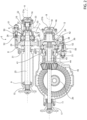
figure 2 is a cross-section view of a distributor system according to a first embodiment of the invention in the configuration offigure 1 ; -
figure 3 is a cross-section view of a distributor system according to a second embodiment of the invention in the configuration offigure 1 ; -
figure 4 is a schematic view of a powertrain system for a heavy vehicle used in a configuration with three driving axles; -
figure 5 is a cross-section view of a distributor system according to a first embodiment of the invention in the configuration offigure 4 ; -
figure 6 is a cross-section view of a distributor system according to a second embodiment of the invention in the configuration offigure 4 ; -
figure 7 is a schematic view of a powertrain system for a heavy vehicle used in a configuration with three driving axles; -
figure 8 is a cross-section view of a distributor system according to a first embodiment of the invention in the configuration offigure 7 ; and -
figure 9 is a cross-section view of a distributor system according to a second embodiment of the invention in the configuration offigure 7 . - The accompanying figures schematically show a powertrain assembly 1 configured to transmit torque, through a mechanical chain, to a plurality of
axles - The powertrain assembly 1 can be an internal combustion engine, a fuel cell system or a hybrid traction system as known in the art.
- The powertrain assembly 1 is connected to at least one axle by means of a
transmission 3, designed to select a specific gearbox, a plurality of rotatingshafts torque distribution system 5 according to the invention. -
Figures 2 and3 show a configuration with two drivingaxles torque distributor 5 is connected by a first rotatingshaft 4a to the powertrain assembly 1, in the case described herein by means of thetransmission 3, and wherein afirst axle 2a is connected by a second rotatingshaft 4b. - In both embodiments, the
torque distributor 5 comprises acasing 6 designed to be supported by a portion fixed to the vehicle frame (not shown) defining aspace 7 and atransmission assembly 8 housed inside thespace 7. - Clearly, the
casing 6 advantageously consists of several parts rigidly connected to one another in order to allow thetransmission assembly 8 to be assembled in thespace 7. - The
casing 6 defines a plurality ofopenings offs transmission 8. - More in detail, the
distributor system 5 defines four openings and respective power take-offs, preferably coaxial to one another two by two. In particular, the first and the second opening 9, 10 and the first and the second power take-off off - Advantageously, the axes A and B are parallel to one another and, even more preferably, are parallel to a longitudinal axis of the vehicle.
- In the embodiment of
figures 2 and3 , corresponding to the embodiment offigure 1 , where there are two traction axles, two power take-offs offs casing 6 by means of connection means 22, such as threaded elements. - In particular, in the configuration described herein, the rotating
shaft 4a is connected to the power take-off 15 and the power take-off 17 is connected to theaxle 2a and to theaxle 2b, as described below, by means of thetransmission 8. - According to the embodiment of
figure 2 , thetransmission 8 comprises afirst support shaft 25 connected to the first power take-off 15 in an integral manner. Thefirst support shaft 25 is connected to the second power take-off 16 by means of a firstdifferential mechanism 26. - In particular, the first
differential mechanism 26 comprises a plurality ofsatellites 27 carried byrespective pins 28 integral to thefirst support shaft 25 and connected by atrain carrier 29. - In particular, the
satellites 27 mesh with a firsttoothed wheel 31 and with a secondtoothed wheel 32. The secondtoothed wheel 32 is carried by thefirst support shaft 25 so as to freely rotate on it and is connected to asecond support shaft 33 that can rigidly be connected to the second power take-off 16. - The first
toothed wheel 31 is carried by thefirst support shaft 25 so as to freely rotate and is operatively connected to the third power take-off 17 by means of a seconddifferential mechanism 36 and to the fourth power take-off 18. - In detail, the second
differential mechanism 36 comprises atrain carrier 39, which is rigidly connected topins 38 supporting thesatellites 37 in a rotary manner and is connected to the firsttoothed wheel 31 by means of a toothed coupling thereto. - The
satellites 37 mesh with a firsttoothed wheel 41 and with a secondtoothed wheel 42. The secondtoothed wheel 42 is rigidly supported by athird support shaft 43 rigidly connected to the third power take-off 17, whereas the first toothed wheel is rigidly carried by afourth support shaft 44 operatively connected to thesecond axle 2b, for example by means of agear 45. - In particular, the
fourth support shaft 44 is carried coaxial to and around thethird support shaft 43. - The
train carrier 39 is rigidly connected to afifth support shaft 46 rigidly connected to the fourth power take-off 18. - With reference to
figure 2 , thefirst support shaft 25 extends along the axis A to a greater extent than thesecond support shaft 33 and stretches above thesecond axle 2b on both sides. - As a result of this arrangement, the second and the fourth power take-
off axle 2b, the third power take-off 17 is located on the opposite side of theaxle 2b, whereas the first power take-off 15 is located substantially above theaxle 2b. - The
transmission 8 further comprises blocking means 50 configured to block the first and/or seconddifferential mechanism space 7. - In particular, the blocking means 50 comprise a
sleeve 51, which is operated by actuator means 52 and is configured to cooperate in contact with an element of thedifferential - In the embodiment shown herein, the blocking means 50 for the first
differential mechanism 36 comprise asleeve 51, which can be moved so as to assumed a a first condition, in which it does not cooperate with thetrain carrier 29, and a second condition, in which it cooperates with thetrain carrier 29 so as to make it selectively integral to the secondtoothed wheel 32. - On the other hand, the blocking means 50 for the second
differential mechanism 36 comprise asleeve 51, which can be moved so as to assume a first condition, in which it does not cooperate with thetrain carrier 39, and a second condition, in which it cooperates with thetrain carrier 39 so as to make it selectively integral to the secondtoothed wheel 42. - The actuator means 52 shown herein advantageously are pneumatic, i.e. they comprise a compressed-air operated piston, which is held in the position of release of the differential by elastic means, which are not further described for the sake of brevity and are not shown in the drawings. In particular, the elastic means are configured to keep the
sleeve 51 in the condition of non-engagement with the relative aforementioned element of the first orsecond differential - In particular, in this configuration, the
first differential 26 is held in a blocked configuration by means of ablocking screw 53. - According to the embodiment of
figure 3 , thetransmission 8 comprises afirst support shaft 25 connected to the first power take-off 15 in an integral manner. Thefirst support shaft 25 is connected to the second power take-off 16 by means of a firstdifferential mechanism 26. - In particular, the
first differential mechanism 26 comprises a plurality ofsatellites 27 carried byrespective pins 28 integral to thefirst support shaft 25 and connected by atrain carrier 29. - In particular, the
satellites 27 mesh with a firsttoothed wheel 31 and with a secondtoothed wheel 32. The secondtoothed wheel 32 is carried by thefirst support shaft 25 so as to freely rotate on it and is connected to asecond support shaft 33 that can rigidly be connected to the second power take-off 16. - The first
toothed wheel 31 is carried by thefirst support shaft 25 so as to freely rotate and is operatively connected to the third power take-off 17 by means of agearing 60 and, by means of saidgearing 60 and of asecond differential mechanism 36, to the fourth power take-off 18. - In detail, the
second differential mechanism 36 comprises atrain carrier 39, which is rigidly connected topins 38 supporting thesatellites 37 in a rotary manner and is connected to the firsttoothed wheel 31 by means of theaforesaid gearing 60. - The
satellites 37 mesh with a firsttoothed wheel 41 and with a secondtoothed wheel 42. The secondtoothed wheel 42 is rigidly supported by athird support shaft 43 rigidly connected to the fourth power take-off 18, whereas the first toothed wheel is rigidly carried by afourth support shaft 44 operatively connected to thesecond axle 2b, for example by means of agear 45. - In particular, the
fourth support shaft 44 is carried coaxial to and around thethird support shaft 43. - The
train carrier 39 is rigidly connected to afifth support shaft 46 rigidly connected to the third power take-off 17. - The
gearing 60 advantageously is a parallel-shaft gearing and comprises anintermediate support shaft 61 rigidly supporting atoothed wheel 62 configured to mesh, on one side, with the firsttoothed wheel 31 of the first differential 26 and, on the other side, with thetrain carrier 39 of the second differential 36. - Advantageously, the
support shaft 61 could be able to be connected to other operating elements of the vehicle, providing a fifth and sixth power take-off, as shown herein, isolated from the external environment by means of covers. - With reference to
figure 3 , thefirst support shaft 25 extends along the axis A to a smaller extent than thesecond support shaft 33 and the latter stretches above thesecond axle 2b on both sides. - As a result of this arrangement, the first and the third power take-
off axle 2b, the fourth power take-off 18 is located on the opposite side of theaxle 2b, whereas the second power take-off 16 is located substantially above theaxle 2b. - The
transmission 8 further comprises blocking means 50 configured to block the first and/or seconddifferential mechanism space 7. - In particular, the blocking means 50 comprise a
sleeve 51, which is operated by actuator means 52 and is configured to cooperate in contact with an element of the differential 26, 36 in order to block the function thereof, i.e. to cause each element thereof to rotate at the same speed. - In the embodiment shown herein, the blocking means 50 for the
first differential mechanism 36 comprise asleeve 51, which can be moved so as to assumed a a first condition, in which it does not cooperate with thetrain carrier 29, and a second condition, in which it cooperates with thetrain carrier 29 so as to make it selectively integral to the secondtoothed wheel 32. - On the other hand, the blocking means 50 for the
second differential mechanism 36 comprise asleeve 51, which can be moved so as to assume a first condition, in which it does not cooperate with thetrain carrier 39, and a second condition, in which it cooperates with thetrain carrier 39 so as to make it selectively integral to the secondtoothed wheel 41. - The actuator means 52 shown herein advantageously are pneumatic, i.e. they comprise a compressed-air operated piston, which is held in the position of release of the differential by elastic means, which are not further described for the sake of brevity and are not shown in the drawings. In particular, the elastic means are configured to keep the
sleeve 51 in the condition of non-engagement with the relative aforementioned element of the first or second differential 26, 36. - In particular, in this configuration, the first differential 26 is held in a blocked configuration by means of a blocking
screw 53. - In the embodiment of
figures 4 ,5 and6 , the vehicle comprises three drivingaxles figures 1 ,2 and3 , the fourth power take-off 18 is connected to a thirdrotating shaft 4c, which connects thetransmission 8 to thethird axle 2c. The connection of the thirdrotating shaft 4c to the axle shafts of thethird axle 2c can be made as described above for thesecond axle 2b. - In the embodiment of
figures 7 ,8 and9 , the vehicle comprises four drivingaxles figures 1 ,2 and3 , the fourth power take-off 18 is connected to a thirdrotating shaft 4c, which connects thetransmission 8 to thethird axle 2c, and the second power take-off 16 is connected to a fourthrotating shaft 4d, which connects thetransmission 8 to thefourth axle 2d. The connection of the third and of the fourthrotating shaft fourth axle second axle 2b. In this configuration, the first differential 26 is free, i.e. it is not blocked by thescrew 53 like in the previous embodiments. - The wheels described in the previous description have straight teeth and are carried by the respective shafts, as described above, in a known manner, for example by means of fitting, bushings or other forms of connection that are integral or free in their rotation. Clearly, although not expressly described, all shafts are carried by the casing in a rotary manner by means of rolling elements, such as bearings, in different mounting configurations.
- The operation of the embodiments disclosed above is the following.
- In the embodiment of
figure 2 , the torque generated by the powertrain 1 is transmitted, through therotating shaft 4a, to the first power take-off 15 at thefirst support shaft 25. Here, torque is delivered to thesatellites 27 by means of thepins 28 of thefirst differential mechanism 26, which provides torque to thetoothed wheels train carrier 39 of the second differential 36, torque is directly supplied to the fourth power take-off 18 and distributed, by means of thetoothed wheels second axle 2b and to the third power take-off 17. In this case, the second and the fourth power take-off respective covers rotating shaft 4b, to thefirst axle 2a, which is a driving axle. - If necessary, the blocking means 50 can be activated for the
second differential mechanism 36 so as to cause theshafts first mechanism 26 is kept blocked by thescrew 53. - In the embodiment of
figure 3 , the torque generated by the powertrain 1 is transmitted, through therotating shaft 4a, to the first power take-off 15 at thefirst support shaft 25. Here, torque is delivered to thesatellites 27 by means of thepins 28 of thefirst differential mechanism 26, which provides torque to thetoothed wheels train carrier 39 of the second differential 36, torque is directly supplied to the fourth power take-off 18 and distributed, by means of thetoothed wheels second axle 2b and to the third power take-off 17. In this case, the second and the fourth power take-off respective covers rotating shaft 4b, to thefirst axle 2a, which is a driving axle. - If necessary, the blocking means 50 can be activated for the
second differential mechanism 36 so as to cause theshafts first mechanism 26 is kept blocked by thescrew 53. - In the embodiment of
figures 5 and6 , the fourth power take-off 18 is connected, by means of the thirdrotating shaft 4c, to athird driving axle 2c and the torque is provided, as discussed above, by the second power take-off. The operation is otherwise similar to that described in relation tofigures 2 and3 . - In the embodiment of
figures 8 and9 , in addition to the information disclosed forfigures 5 and6 , the second power take-off 16 is connected, by means of the fourthrotating shaft 4d, to afourth driving axle 2d and the torque is provided, as discussed above, by the second power take-off. The operation is otherwise similar to that described in relation tofigures 2 and3 , in particular the first differential 26, in this case, effectively distributes the torque between thewheels - Owing to the above, the advantages of a torque distributor system according to the invention are evident.
- The distributor system disclosed herein allows for a distribution, in a versatile manner, to different axles of a vehicle, thus allowing manufacturers, with the same system, to obtain different vehicle configurations of driving axles.
- Therefore, the distributor system according to the invention is particularly versatile, i.e. it is suitable for a wide variety of purposes, reducing manufacturing costs and permitting a high customisation of the vehicle.
- Furthermore, the fact that the transmission is housed within a single space, and the fact that the power take-offs can be isolated when they are not used increase the useful life of the transmission.
- The use of two differentials connected by one or more gears also allows manufacturers to have axles with equal traction that can be used in the conditions required by specific load and/or terrain situations.
- Furthermore, the special arrangement of the shafts astride the axle interposed between the two parts of the transmission makes it possible to obtain a particularly compact distributor.
- Finally, the torque distributor system according to the invention can be subjected to changes and variants, which, though, do not go beyond the scope of protection set forth in the appended claims.
- Clearly, further mechanical elements can be provided, which are not described herein for the sake of brevity.
- The reduction module and the differential mechanisms or the blocking means could comprise elements with a different shape.
- Similarly, the arrangement of the power take-offs could change and further reduction stages could be provided between them.
- Clearly, although toothed wheels with straight teeth were described, there could be different types of toothed wheels and of teeth. In addition, further constructive elements omitted from the description and merely outlined in the drawings for the sake of brevity could be present so as to allow shafts and toothed wheels to be correctly mounted.
Claims (15)
- Torque distributor system (5) for distributing the torque coming from a powertrain (1) of a vehicle to a plurality of axles (2a, 2b, 2c, 2d) of said vehicle,
said distributor system (5) comprising a casing (6) suitable for defining a space (7) configured to house a transmission (8), said casing (6) defining a plurality of openings (9, 10, 11, 12) configured for housing respective power take-offs (15, 16, 17, 18) connected to each other by said transmission (8), a first power take-off (15) of said power take-offs 15, 16, 17, 18) being connectable to said powerplant (1) and at least one second (19) of said power take-offs (15, 16, 17, 18) being connectable to one or more of said axles (2a, 2b, 2c, 2d), said power take-offs (15, 16, 17, 18) being coaxial in pairs along respective axes (A, B),
said transmission (8) comprising a first differential mechanism (26) operationally interposed between said first and second power take-offs (15, 16) and a second differential mechanism (36), each respectively comprising a plurality of satellites (27, 37 ) carried by pins (28, 38) connected to a train carrier (29, 39), said satellites (27, 37) meshing with respective first and second toothed wheels (31, 32, 41, 42), said second differential mechanism (36) being operationally interposed between one of said third and fourth power take-offs (17, 18) and said first power take-off (15), said second differential mechanism (36) being operationally connected to said first gear wheel (31) of said first differential (26). - System according to claim 1, in which said second gear wheel (32) of said first differential (26) is rigidly connected to said second power take-off (16).
- System according to claim 1 or 2, in which said second differential mechanism (36) is operationally interposed between said third power take-off (17) and said first power take-off (36), said fourth power take-off (18 ) being operationally connected to said toothed wheel (31).
- System according to one of claims 1 to 3, in which said transmission (8) includes a first support shaft (25) rigidly connected to said first power take-off (15), said first support shaft (25) said pins of said first differential mechanism (26), said first gear wheel (31) being operationally connected to said train holder (39) of said second differential mechanism (36).
- System according to claim 4, in which said train carrier (39) of said second differential mechanism (36) is rigidly connected to said fourth power take-off (18).
- System according to claim 4 or 5, in which said first toothed wheel (41) of said second differential mechanism (36) is operationally connected to one of said axles (2b), said second toothed wheel (42) of said second differential mechanism (36) is rigidly connected to said third power take-off (17).
- System according to claim 4, in which said train carrier (39) of said second differential mechanism (36) is rigidly connected to said third power take-off (17).
- System according to claim 4 or 7, in which said first toothed wheel (41) of said second differential mechanism (36) is operationally connected to one of said axles (2b), said second toothed wheel (42) of said second differential mechanism (36) is rigidly connected to said fourth power take-off (18).
- System according to one of claims 4 to 8, in which said first gear wheel (31) is operationally connected to said train carrier (39) of said second differential (36) via a gearing (60).
- System according to claim 9, in which said gearing (60) has parallel shafts.
- System according to claim 9 or 10, wherein said gearing (60) comprises a support shaft (61) rigidly supporting a gear wheel (62), said gear wheel (62) meshing with said first gear wheel (31) of said first differential (26) and said train carrier (39) of said second differential (36).
- System according to one of claims 4 to 11, wherein said first differential mechanism (26) includes a locking screw (53) rigidly connecting said second gear wheel (32) to said first support shaft (25).
- System according to one of claims 4 to 12, in which said first support shaft (25) is carried vertically above said one of said axles (2a, 2b, 2c, 2d).
- System according to claims one of the previous claims, wherein said transmission (8) includes blocking means (50) for blocking said first and second differential mechanisms (26, 36).
- Vehicle comprising a powerplant (1) capable of generating torque, a plurality of axles (2a, 2b, 2c, 2d) and a torque distributor (5) according to one of the previous claims and operationally interposed between said powerplant (1) and said axles (2a, 2b, 2c, 2d).
Applications Claiming Priority (1)
| Application Number | Priority Date | Filing Date | Title |
|---|---|---|---|
| IT102023000020277A IT202300020277A1 (en) | 2023-10-02 | 2023-10-02 | IMPROVED TORQUE DISTRIBUTION SYSTEM BETWEEN HEAVY DUTY VEHICLE AXLES |
Publications (1)
| Publication Number | Publication Date |
|---|---|
| EP4534318A1 true EP4534318A1 (en) | 2025-04-09 |
Family
ID=89157976
Family Applications (1)
| Application Number | Title | Priority Date | Filing Date |
|---|---|---|---|
| EP24203517.8A Pending EP4534318A1 (en) | 2023-10-02 | 2024-09-30 | Improved torque distributor system among axles of a heavy vehicle |
Country Status (2)
| Country | Link |
|---|---|
| EP (1) | EP4534318A1 (en) |
| IT (1) | IT202300020277A1 (en) |
Citations (1)
| Publication number | Priority date | Publication date | Assignee | Title |
|---|---|---|---|---|
| EP4238802A1 (en) * | 2022-02-09 | 2023-09-06 | Iveco S.P.A. | Improved torque distributor system among axles of a heavy vehicle |
-
2023
- 2023-10-02 IT IT102023000020277A patent/IT202300020277A1/en unknown
-
2024
- 2024-09-30 EP EP24203517.8A patent/EP4534318A1/en active Pending
Patent Citations (1)
| Publication number | Priority date | Publication date | Assignee | Title |
|---|---|---|---|---|
| EP4238802A1 (en) * | 2022-02-09 | 2023-09-06 | Iveco S.P.A. | Improved torque distributor system among axles of a heavy vehicle |
Also Published As
| Publication number | Publication date |
|---|---|
| IT202300020277A1 (en) | 2025-04-02 |
Similar Documents
| Publication | Publication Date | Title |
|---|---|---|
| CN110154647B (en) | Drive axle assembly with clutch collar | |
| US20200189375A1 (en) | Vehicle electric drive system | |
| CN112644273B (en) | Axle assembly with differential assembly | |
| US20240270067A1 (en) | Vehicle driving assembly and vehicle | |
| EP3789223B1 (en) | Electric modular traction system | |
| US7074149B2 (en) | Transmission for wheel type working vehicle | |
| KR20060043850A (en) | Dual speed all-wheel drive system | |
| KR20220141450A (en) | Power transmission device for vehicle having electric-axle | |
| CN115704462A (en) | Transmission for a vehicle and drive train having such a transmission | |
| EP4399111B1 (en) | Traction assembly for a vehicle | |
| EP4422898B1 (en) | Traction assembly for a vehicle | |
| EP4534318A1 (en) | Improved torque distributor system among axles of a heavy vehicle | |
| EP4238802B1 (en) | Improved torque distributor system among axles of a heavy vehicle | |
| US12128760B2 (en) | Powertrain for a vehicle and a vehicle | |
| EP4257389A1 (en) | Improved torque distribution system among axles of a heavy vehicle | |
| EP4257388A1 (en) | Improved torque distributor system among axles of a heavy vehicle | |
| EP4257401A1 (en) | Improved torque distributor system among axles of a heavy vehicle | |
| EP4202261B1 (en) | Improved hybrid driving front axle for an agricultural vehicle | |
| CN112555378B (en) | Axle assembly with gear mechanism | |
| CN115704461A (en) | Transmission for a vehicle and drive train having such a transmission | |
| US12606019B2 (en) | Electric traction axle/beam | |
| EP4144552B1 (en) | Traction assembly for a vehicle | |
| EP4541629A1 (en) | Improved electric traction axle | |
| EP4144554A1 (en) | Traction assembly for a vehicle | |
| CN223890781U (en) | Driving device for all-wheel drive vehicle and vehicle |
Legal Events
| Date | Code | Title | Description |
|---|---|---|---|
| PUAI | Public reference made under article 153(3) epc to a published international application that has entered the european phase |
Free format text: ORIGINAL CODE: 0009012 |
|
| STAA | Information on the status of an ep patent application or granted ep patent |
Free format text: STATUS: THE APPLICATION HAS BEEN PUBLISHED |
|
| AK | Designated contracting states |
Kind code of ref document: A1 Designated state(s): AL AT BE BG CH CY CZ DE DK EE ES FI FR GB GR HR HU IE IS IT LI LT LU LV MC ME MK MT NL NO PL PT RO RS SE SI SK SM TR |
|
| STAA | Information on the status of an ep patent application or granted ep patent |
Free format text: STATUS: REQUEST FOR EXAMINATION WAS MADE |
|
| 17P | Request for examination filed |
Effective date: 20251007 |