EP4534315A1 - Fuel tank for vehicles - Google Patents
Fuel tank for vehicles Download PDFInfo
- Publication number
- EP4534315A1 EP4534315A1 EP24204182.0A EP24204182A EP4534315A1 EP 4534315 A1 EP4534315 A1 EP 4534315A1 EP 24204182 A EP24204182 A EP 24204182A EP 4534315 A1 EP4534315 A1 EP 4534315A1
- Authority
- EP
- European Patent Office
- Prior art keywords
- fuel tank
- ring
- container
- coupling flange
- ring gasket
- Prior art date
- Legal status (The legal status is an assumption and is not a legal conclusion. Google has not performed a legal analysis and makes no representation as to the accuracy of the status listed.)
- Pending
Links
Images


Classifications
-
- B—PERFORMING OPERATIONS; TRANSPORTING
- B60—VEHICLES IN GENERAL
- B60K—ARRANGEMENT OR MOUNTING OF PROPULSION UNITS OR OF TRANSMISSIONS IN VEHICLES; ARRANGEMENT OR MOUNTING OF PLURAL DIVERSE PRIME-MOVERS IN VEHICLES; AUXILIARY DRIVES FOR VEHICLES; INSTRUMENTATION OR DASHBOARDS FOR VEHICLES; ARRANGEMENTS IN CONNECTION WITH COOLING, AIR INTAKE, GAS EXHAUST OR FUEL SUPPLY OF PROPULSION UNITS IN VEHICLES
- B60K15/00—Arrangement in connection with fuel supply of combustion engines or other fuel consuming energy converters, e.g. fuel cells; Mounting or construction of fuel tanks
- B60K15/03—Fuel tanks
-
- B—PERFORMING OPERATIONS; TRANSPORTING
- B60—VEHICLES IN GENERAL
- B60K—ARRANGEMENT OR MOUNTING OF PROPULSION UNITS OR OF TRANSMISSIONS IN VEHICLES; ARRANGEMENT OR MOUNTING OF PLURAL DIVERSE PRIME-MOVERS IN VEHICLES; AUXILIARY DRIVES FOR VEHICLES; INSTRUMENTATION OR DASHBOARDS FOR VEHICLES; ARRANGEMENTS IN CONNECTION WITH COOLING, AIR INTAKE, GAS EXHAUST OR FUEL SUPPLY OF PROPULSION UNITS IN VEHICLES
- B60K15/00—Arrangement in connection with fuel supply of combustion engines or other fuel consuming energy converters, e.g. fuel cells; Mounting or construction of fuel tanks
- B60K15/03—Fuel tanks
- B60K15/04—Tank inlets
- B60K15/0406—Filler caps for fuel tanks
-
- B—PERFORMING OPERATIONS; TRANSPORTING
- B60—VEHICLES IN GENERAL
- B60K—ARRANGEMENT OR MOUNTING OF PROPULSION UNITS OR OF TRANSMISSIONS IN VEHICLES; ARRANGEMENT OR MOUNTING OF PLURAL DIVERSE PRIME-MOVERS IN VEHICLES; AUXILIARY DRIVES FOR VEHICLES; INSTRUMENTATION OR DASHBOARDS FOR VEHICLES; ARRANGEMENTS IN CONNECTION WITH COOLING, AIR INTAKE, GAS EXHAUST OR FUEL SUPPLY OF PROPULSION UNITS IN VEHICLES
- B60K15/00—Arrangement in connection with fuel supply of combustion engines or other fuel consuming energy converters, e.g. fuel cells; Mounting or construction of fuel tanks
- B60K15/03—Fuel tanks
- B60K15/04—Tank inlets
- B60K15/0406—Filler caps for fuel tanks
- B60K2015/0432—Filler caps for fuel tanks having a specific connection between the cap and the vehicle or tank opening
- B60K2015/0438—Filler caps for fuel tanks having a specific connection between the cap and the vehicle or tank opening using screw or bayonet
-
- B—PERFORMING OPERATIONS; TRANSPORTING
- B60—VEHICLES IN GENERAL
- B60K—ARRANGEMENT OR MOUNTING OF PROPULSION UNITS OR OF TRANSMISSIONS IN VEHICLES; ARRANGEMENT OR MOUNTING OF PLURAL DIVERSE PRIME-MOVERS IN VEHICLES; AUXILIARY DRIVES FOR VEHICLES; INSTRUMENTATION OR DASHBOARDS FOR VEHICLES; ARRANGEMENTS IN CONNECTION WITH COOLING, AIR INTAKE, GAS EXHAUST OR FUEL SUPPLY OF PROPULSION UNITS IN VEHICLES
- B60K15/00—Arrangement in connection with fuel supply of combustion engines or other fuel consuming energy converters, e.g. fuel cells; Mounting or construction of fuel tanks
- B60K15/03—Fuel tanks
- B60K15/04—Tank inlets
- B60K15/0406—Filler caps for fuel tanks
- B60K2015/0451—Sealing means in the closure cap
Definitions
- the present invention relates to a fuel tank for vehicles.
- the present invention relates to a fuel tank for vehicles of the type comprising a container for storing fuel; a supply pump mounted inside the container; and a closing plate for the container.
- the container has an opening provided with an inner coupling flange configured to be coupled in a fluid-tight manner, through the interposition of a ring gasket, to an outer coupling flange obtained on the closing plate.
- the tank further comprises a locking ring for axially locking the closing plate on the inner coupling flange of the container with the interposition of the mentioned ring gasket.
- the known fuel tanks for vehicles of the type described above have some drawbacks mainly deriving from the fact that the mentioned ring gasket is unable to limit the leakage between the locking ring and the inner and outer coupling flanges of the vapours generated by the fuel inside the container.
- the object of the present invention is to provide a fuel tank for vehicles which is exempt from the drawbacks set forth above and which is simple and cost-effective to manufacture.
- a fuel tank for vehicles is provided as claimed in the appended claims.
- reference numeral 1 indicates, as a whole, a fuel tank for vehicles comprising a container 2 for storing fuel provided with an upper opening 3 having, in this case, a circular shape.
- the opening 3 has a longitudinal axis 4, is axially limited by a substantially flat upper surface 5 coaxial to the axis 4, and is provided with an inner coupling flange 6 radially protruding inwards from the opening 3.
- the flange 6 has an annular, in this case circular, shape and is axially limited by an upper surface 7 and a lower surface 8 substantially parallel to each other and perpendicular to the axis 4.
- the opening 3 is closed by a closing plate 9, in this case having a circular shape, which is mounted inside the opening 3 coaxial to the axis 4, and is provided with an outer coupling flange 10 configured to be coupled to the flange 6.
- the flange 10 has an annular, in this case circular, shape and is axially limited by a lower surface 11 facing the surface 7 and by an upper surface 12 substantially coplanar to the surface 5 of the opening 3.
- the flange 6 is provided with an annular cavity 13, which extends coaxial to the axis 4, opens outwards at the surface 7, and accommodates, on the inside, a ring gasket 14 configured to couple the flanges 6 and 10 to each other in a fluid-tight manner.
- the tank 1 further comprises a locking ring 15, which extends coaxial to the axis 4, and is screwed on the surface 5 of the opening 3 for axially locking the flange 10 on the flange 6 with the interposition of the gasket 14.
- the ring 15 is axially limited by a lower surface 16 facing both the surface 5 of the opening 3, and the surface 12 of the flange 10, and is provided with an annular cavity 17, which extends coaxial to the axis 4, opens outwards at the surface 16, and is limited by a bottom wall 18 substantially perpendicular to the axis 4.
- the cavity 17 accommodates, on the inside, a ring gasket 19 configured to couple the opening 3, the flange 10, and the ring 15 to one another in a fluid-tight manner.
- the gasket 19 is provided with a plurality of coupling teeth 20, which are distributed around the axis 4, and are configured to be coupled through interference to corresponding recesses (not illustrated) obtained on the wall 18 so as to hook the gasket 19 to the ring 15.
- the gasket 19 is further provided with two annular teeth 21, 22, which are coaxial to each other and to the axis 4, and are configured to be coupled to the surface 5 of the opening 3 and to the surface 12 of the flange 10, respectively, in a fluid-tight manner.
- the gasket 19 is overmoulded inside the cavity 17 of the ring 15.
- the tank 1 further comprises a known supply pump not shown, which is housed inside the container 2, and is connected to a fitting 23 obtained on the plate 9 by means of a supply duct housed inside the container 2.
- the tank 1 has some advantages mainly deriving from the fact that the presence of the gaskets 14 and 19 allows at least limiting the leakage between the opening 3, the closing plate 9, and the locking ring 15 of the vapours generated by the fuel inside the container 2.
Landscapes
- Engineering & Computer Science (AREA)
- Life Sciences & Earth Sciences (AREA)
- Sustainable Development (AREA)
- Sustainable Energy (AREA)
- Chemical & Material Sciences (AREA)
- Combustion & Propulsion (AREA)
- Transportation (AREA)
- Mechanical Engineering (AREA)
- Cooling, Air Intake And Gas Exhaust, And Fuel Tank Arrangements In Propulsion Units (AREA)
- Closures For Containers (AREA)
Abstract
A fuel tank for vehicles is provided with a container (2) for storing fuel having an opening (3) limited by an inner coupling flange (6), with a closing plate (9) for the container (2) limited by an outer coupling flange (10) configured to be coupled to the inner coupling flange (6) in a fluid-tight manner through the interposition of a first ring gasket (14), and with a second ring gasket (19) to couple the opening (3), the closing plate (9), and a locking ring (15) of the closing plate (9) on the container (2) to one another in a fluid-tight manner.
Description
- This patent application claims priority from
Italian patent application no. 102023000020535 filed on October 4, 2023 - The present invention relates to a fuel tank for vehicles.
- In particular, the present invention relates to a fuel tank for vehicles of the type comprising a container for storing fuel; a supply pump mounted inside the container; and a closing plate for the container.
- The container has an opening provided with an inner coupling flange configured to be coupled in a fluid-tight manner, through the interposition of a ring gasket, to an outer coupling flange obtained on the closing plate.
- The tank further comprises a locking ring for axially locking the closing plate on the inner coupling flange of the container with the interposition of the mentioned ring gasket.
- The known fuel tanks for vehicles of the type described above have some drawbacks mainly deriving from the fact that the mentioned ring gasket is unable to limit the leakage between the locking ring and the inner and outer coupling flanges of the vapours generated by the fuel inside the container.
- The object of the present invention is to provide a fuel tank for vehicles which is exempt from the drawbacks set forth above and which is simple and cost-effective to manufacture.
- According to the present invention, a fuel tank for vehicles is provided as claimed in the appended claims.
- The present invention will now be described with reference to the accompanying drawings, which illustrate a non-limiting example embodiment thereof, wherein:
-
Figure 1 is a schematic perspective view, with parts removed for clarity, of a preferred embodiment of the fuel tank of the present invention; -
Figure 2 is an exploded schematic perspective view, with parts removed for clarity, of a detail of the fuel tank ofFigure 1 ; and -
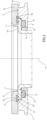
Figure 3 is a schematic longitudinal section, with parts removed for clarity, of the detail ofFigure 2 . - With reference to
Figures 1 ,2 , and3 , reference numeral 1 indicates, as a whole, a fuel tank for vehicles comprising acontainer 2 for storing fuel provided with anupper opening 3 having, in this case, a circular shape. - The
opening 3 has a longitudinal axis 4, is axially limited by a substantially flatupper surface 5 coaxial to the axis 4, and is provided with an inner coupling flange 6 radially protruding inwards from theopening 3. - The flange 6 has an annular, in this case circular, shape and is axially limited by an
upper surface 7 and alower surface 8 substantially parallel to each other and perpendicular to the axis 4. - The
opening 3 is closed by aclosing plate 9, in this case having a circular shape, which is mounted inside the opening 3 coaxial to the axis 4, and is provided with anouter coupling flange 10 configured to be coupled to the flange 6. - The
flange 10 has an annular, in this case circular, shape and is axially limited by alower surface 11 facing thesurface 7 and by anupper surface 12 substantially coplanar to thesurface 5 of theopening 3. - The flange 6 is provided with an
annular cavity 13, which extends coaxial to the axis 4, opens outwards at thesurface 7, and accommodates, on the inside, aring gasket 14 configured to couple theflanges 6 and 10 to each other in a fluid-tight manner. - The tank 1 further comprises a
locking ring 15, which extends coaxial to the axis 4, and is screwed on thesurface 5 of theopening 3 for axially locking theflange 10 on the flange 6 with the interposition of thegasket 14. - The
ring 15 is axially limited by alower surface 16 facing both thesurface 5 of theopening 3, and thesurface 12 of theflange 10, and is provided with anannular cavity 17, which extends coaxial to the axis 4, opens outwards at thesurface 16, and is limited by abottom wall 18 substantially perpendicular to the axis 4. - The
cavity 17 accommodates, on the inside, aring gasket 19 configured to couple theopening 3, theflange 10, and thering 15 to one another in a fluid-tight manner. - The
gasket 19 is provided with a plurality ofcoupling teeth 20, which are distributed around the axis 4, and are configured to be coupled through interference to corresponding recesses (not illustrated) obtained on thewall 18 so as to hook thegasket 19 to thering 15. - The
gasket 19 is further provided with twoannular teeth surface 5 of theopening 3 and to thesurface 12 of theflange 10, respectively, in a fluid-tight manner. - According to a variation not shown, the
gasket 19 is overmoulded inside thecavity 17 of thering 15. - The tank 1 further comprises a known supply pump not shown, which is housed inside the
container 2, and is connected to afitting 23 obtained on theplate 9 by means of a supply duct housed inside thecontainer 2. - The tank 1 has some advantages mainly deriving from the fact that the presence of the
gaskets opening 3, theclosing plate 9, and thelocking ring 15 of the vapours generated by the fuel inside thecontainer 2.
Claims (10)
- A fuel tank for vehicles comprising a container (2) for storing fuel having an opening (3) provided with an inner coupling flange (6); a pumping device mounted inside the container (2); a closing plate (9) for the container (2) provided with an outer coupling flange (10) configured to be coupled to the inner coupling flange (6); a first ring gasket (14) to couple the inner and outer coupling flanges (6, 10) to each other in a fluid-tight manner; and a locking ring (15) to axially lock the closing plate (9) on the container (2) with the interposition of the first ring gasket (14); and characterized in that it further comprises a second ring gasket (19) to couple the opening (3), the closing plate (9) and the locking ring (15) to one another in a fluid-tight manner.
- The fuel tank according to claim 1, wherein the first ring gasket (14) is mounted between the inner coupling flange (6) and the outer coupling flange (10).
- The fuel tank according to claim 1 or 2, wherein the second ring gasket (19) is mounted between the opening (3), the outer coupling flange (10) and the locking ring (15) .
- The fuel tank according to any one of the preceding claims, wherein the inner coupling flange (6) has a first annular seat (13) configured to house, on the inside, the first ring gasket (14).
- The fuel tank according to any one of the preceding claims, wherein the locking ring (15) has a second annular seat (17) configured to house, on the inside, the second ring gasket (19).
- The fuel tank according to any one of the preceding claims, wherein the second ring gasket (19) is coupled to the locking ring (15) through interference.
- The fuel tank according to claim 6, wherein the second ring gasket (19) has a plurality of coupling teeth (20) coupled, through interference, to corresponding recesses obtained on the locking ring (15).
- The fuel tank according to any one of the claims from 1 to 5, wherein the second ring gasket (19) is overmoulded on the locking ring (15).
- The fuel tank according to any one of the preceding claims, wherein the second ring gasket (19) is provided with a first annular tooth (21) configured to be coupled to the opening (3) in a fluid-tight manner and with a second annular tooth (22) configured to be coupled to the outer coupling flange (10) in a fluid-tight manner.
- The fuel tank according to any one of the preceding claims and further comprising a supply duct mounted inside the container (2) so as to connect the pumping device and a fitting (23) obtained on the closing plate (9) to each other.
Applications Claiming Priority (1)
| Application Number | Priority Date | Filing Date | Title |
|---|---|---|---|
| IT102023000020535A IT202300020535A1 (en) | 2023-10-04 | 2023-10-04 | FUEL TANK FOR VEHICLES |
Publications (1)
| Publication Number | Publication Date |
|---|---|
| EP4534315A1 true EP4534315A1 (en) | 2025-04-09 |
Family
ID=89158535
Family Applications (1)
| Application Number | Title | Priority Date | Filing Date |
|---|---|---|---|
| EP24204182.0A Pending EP4534315A1 (en) | 2023-10-04 | 2024-10-02 | Fuel tank for vehicles |
Country Status (2)
| Country | Link |
|---|---|
| EP (1) | EP4534315A1 (en) |
| IT (1) | IT202300020535A1 (en) |
Citations (4)
| Publication number | Priority date | Publication date | Assignee | Title |
|---|---|---|---|---|
| US20040069782A1 (en) * | 2002-10-09 | 2004-04-15 | Natsushi Miura | Filler neck |
| US9694673B2 (en) * | 2015-09-25 | 2017-07-04 | Nissan North America, Inc. | Tank assembly with retaining ring |
| US20170334286A1 (en) * | 2016-05-23 | 2017-11-23 | Yamaha Hatsudoki Kabushiki Kaisha | Fuel tank |
| US20230256813A1 (en) * | 2020-07-06 | 2023-08-17 | KÖHLER AUTOMOBILTECHNIK GmbH | Tank Closure for Motor Vehicles |
-
2023
- 2023-10-04 IT IT102023000020535A patent/IT202300020535A1/en unknown
-
2024
- 2024-10-02 EP EP24204182.0A patent/EP4534315A1/en active Pending
Patent Citations (4)
| Publication number | Priority date | Publication date | Assignee | Title |
|---|---|---|---|---|
| US20040069782A1 (en) * | 2002-10-09 | 2004-04-15 | Natsushi Miura | Filler neck |
| US9694673B2 (en) * | 2015-09-25 | 2017-07-04 | Nissan North America, Inc. | Tank assembly with retaining ring |
| US20170334286A1 (en) * | 2016-05-23 | 2017-11-23 | Yamaha Hatsudoki Kabushiki Kaisha | Fuel tank |
| US20230256813A1 (en) * | 2020-07-06 | 2023-08-17 | KÖHLER AUTOMOBILTECHNIK GmbH | Tank Closure for Motor Vehicles |
Also Published As
| Publication number | Publication date |
|---|---|
| IT202300020535A1 (en) | 2025-04-04 |
Similar Documents
| Publication | Publication Date | Title |
|---|---|---|
| US6182693B1 (en) | Vapor canister and fuel tank assembly | |
| US8857643B2 (en) | Vessel for storing a fuel and/or operating medium for vehicles | |
| CN101952134B (en) | Fuel tank for motor vehicles made of thermoplastic plastic | |
| JP4937236B2 (en) | Fuel tank connector and check valve | |
| KR102240601B1 (en) | Keyed thread engagement on spin-on filter element | |
| JP2004515687A (en) | Apparatus for fueling internal combustion engines | |
| JP2009501104A (en) | Tank supply pipe | |
| EP3402689B1 (en) | Closure assembly for fuel-tank filler neck | |
| KR102587123B1 (en) | Connector assemblies, plates for use with such assemblies, and cooling systems incorporating such assemblies. | |
| KR20130014680A (en) | Neck assembly | |
| EP4534315A1 (en) | Fuel tank for vehicles | |
| US7228847B2 (en) | Cover assembly for fuel tank | |
| CA2368603A1 (en) | Fuel tank with lid | |
| CN108136894B (en) | container including reinforcement | |
| US20130114920A1 (en) | Shaft Penetration of a Housing of an Internal Combustion Engine and Bearing of a Shaft Penetration | |
| US6189716B1 (en) | Secondary sealing of a fuel tank | |
| CN105026659A (en) | Tap aerator comprising a mounting housing | |
| KR20220050225A (en) | pipe joint member | |
| US20090134088A1 (en) | Fluid filter for automatic transmission and installation method for the same | |
| CA3063573C (en) | Spin-on filter assembly with nut plate | |
| JP2021133759A (en) | Fuel filler | |
| US20160159565A1 (en) | Double wall liquid storage tank with sealing gasket and compression fitting | |
| EP1862667B1 (en) | Holding member for fuel injection valve | |
| US3648730A (en) | Pressurized fluid storage tank | |
| US20160061312A1 (en) | Transmission shipping plug and method of assembly |
Legal Events
| Date | Code | Title | Description |
|---|---|---|---|
| PUAI | Public reference made under article 153(3) epc to a published international application that has entered the european phase |
Free format text: ORIGINAL CODE: 0009012 |
|
| STAA | Information on the status of an ep patent application or granted ep patent |
Free format text: STATUS: THE APPLICATION HAS BEEN PUBLISHED |
|
| AK | Designated contracting states |
Kind code of ref document: A1 Designated state(s): AL AT BE BG CH CY CZ DE DK EE ES FI FR GB GR HR HU IE IS IT LI LT LU LV MC ME MK MT NL NO PL PT RO RS SE SI SK SM TR |
|
| STAA | Information on the status of an ep patent application or granted ep patent |
Free format text: STATUS: REQUEST FOR EXAMINATION WAS MADE |
|
| 17P | Request for examination filed |
Effective date: 20251006 |