EP4534299A1 - Information recording body, printed article, and reading device for information recording body - Google Patents
Information recording body, printed article, and reading device for information recording body Download PDFInfo
- Publication number
- EP4534299A1 EP4534299A1 EP23811797.2A EP23811797A EP4534299A1 EP 4534299 A1 EP4534299 A1 EP 4534299A1 EP 23811797 A EP23811797 A EP 23811797A EP 4534299 A1 EP4534299 A1 EP 4534299A1
- Authority
- EP
- European Patent Office
- Prior art keywords
- pattern
- information recording
- recording medium
- partial
- ink layer
- Prior art date
- Legal status (The legal status is an assumption and is not a legal conclusion. Google has not performed a legal analysis and makes no representation as to the accuracy of the status listed.)
- Pending
Links
Images








Classifications
-
- G—PHYSICS
- G07—CHECKING-DEVICES
- G07D—HANDLING OF COINS OR VALUABLE PAPERS, e.g. TESTING, SORTING BY DENOMINATIONS, COUNTING, DISPENSING, CHANGING OR DEPOSITING
- G07D7/00—Testing specially adapted to determine the identity or genuineness of valuable papers or for segregating those which are unacceptable, e.g. banknotes that are alien to a currency
- G07D7/06—Testing specially adapted to determine the identity or genuineness of valuable papers or for segregating those which are unacceptable, e.g. banknotes that are alien to a currency using wave or particle radiation
- G07D7/12—Visible light, infrared or ultraviolet radiation
-
- B—PERFORMING OPERATIONS; TRANSPORTING
- B42—BOOKBINDING; ALBUMS; FILES; SPECIAL PRINTED MATTER
- B42D—BOOKS; BOOK COVERS; LOOSE LEAVES; PRINTED MATTER CHARACTERISED BY IDENTIFICATION OR SECURITY FEATURES; PRINTED MATTER OF SPECIAL FORMAT OR STYLE NOT OTHERWISE PROVIDED FOR; DEVICES FOR USE THEREWITH AND NOT OTHERWISE PROVIDED FOR; MOVABLE-STRIP WRITING OR READING APPARATUS
- B42D25/00—Information-bearing cards or sheet-like structures characterised by identification or security features; Manufacture thereof
- B42D25/30—Identification or security features, e.g. for preventing forgery
- B42D25/305—Associated digital information
-
- B—PERFORMING OPERATIONS; TRANSPORTING
- B42—BOOKBINDING; ALBUMS; FILES; SPECIAL PRINTED MATTER
- B42D—BOOKS; BOOK COVERS; LOOSE LEAVES; PRINTED MATTER CHARACTERISED BY IDENTIFICATION OR SECURITY FEATURES; PRINTED MATTER OF SPECIAL FORMAT OR STYLE NOT OTHERWISE PROVIDED FOR; DEVICES FOR USE THEREWITH AND NOT OTHERWISE PROVIDED FOR; MOVABLE-STRIP WRITING OR READING APPARATUS
- B42D25/00—Information-bearing cards or sheet-like structures characterised by identification or security features; Manufacture thereof
- B42D25/30—Identification or security features, e.g. for preventing forgery
- B42D25/351—Translucent or partly translucent parts, e.g. windows
-
- B—PERFORMING OPERATIONS; TRANSPORTING
- B42—BOOKBINDING; ALBUMS; FILES; SPECIAL PRINTED MATTER
- B42D—BOOKS; BOOK COVERS; LOOSE LEAVES; PRINTED MATTER CHARACTERISED BY IDENTIFICATION OR SECURITY FEATURES; PRINTED MATTER OF SPECIAL FORMAT OR STYLE NOT OTHERWISE PROVIDED FOR; DEVICES FOR USE THEREWITH AND NOT OTHERWISE PROVIDED FOR; MOVABLE-STRIP WRITING OR READING APPARATUS
- B42D25/00—Information-bearing cards or sheet-like structures characterised by identification or security features; Manufacture thereof
- B42D25/30—Identification or security features, e.g. for preventing forgery
- B42D25/36—Identification or security features, e.g. for preventing forgery comprising special materials
- B42D25/378—Special inks
- B42D25/382—Special inks absorbing or reflecting infrared light
-
- B—PERFORMING OPERATIONS; TRANSPORTING
- B42—BOOKBINDING; ALBUMS; FILES; SPECIAL PRINTED MATTER
- B42D—BOOKS; BOOK COVERS; LOOSE LEAVES; PRINTED MATTER CHARACTERISED BY IDENTIFICATION OR SECURITY FEATURES; PRINTED MATTER OF SPECIAL FORMAT OR STYLE NOT OTHERWISE PROVIDED FOR; DEVICES FOR USE THEREWITH AND NOT OTHERWISE PROVIDED FOR; MOVABLE-STRIP WRITING OR READING APPARATUS
- B42D25/00—Information-bearing cards or sheet-like structures characterised by identification or security features; Manufacture thereof
- B42D25/30—Identification or security features, e.g. for preventing forgery
- B42D25/36—Identification or security features, e.g. for preventing forgery comprising special materials
- B42D25/378—Special inks
- B42D25/387—Special inks absorbing or reflecting ultraviolet light
-
- G—PHYSICS
- G07—CHECKING-DEVICES
- G07D—HANDLING OF COINS OR VALUABLE PAPERS, e.g. TESTING, SORTING BY DENOMINATIONS, COUNTING, DISPENSING, CHANGING OR DEPOSITING
- G07D7/00—Testing specially adapted to determine the identity or genuineness of valuable papers or for segregating those which are unacceptable, e.g. banknotes that are alien to a currency
- G07D7/004—Testing specially adapted to determine the identity or genuineness of valuable papers or for segregating those which are unacceptable, e.g. banknotes that are alien to a currency using digital security elements, e.g. information coded on a magnetic thread or strip
- G07D7/0043—Testing specially adapted to determine the identity or genuineness of valuable papers or for segregating those which are unacceptable, e.g. banknotes that are alien to a currency using digital security elements, e.g. information coded on a magnetic thread or strip using barcodes
-
- G—PHYSICS
- G07—CHECKING-DEVICES
- G07D—HANDLING OF COINS OR VALUABLE PAPERS, e.g. TESTING, SORTING BY DENOMINATIONS, COUNTING, DISPENSING, CHANGING OR DEPOSITING
- G07D7/00—Testing specially adapted to determine the identity or genuineness of valuable papers or for segregating those which are unacceptable, e.g. banknotes that are alien to a currency
- G07D7/06—Testing specially adapted to determine the identity or genuineness of valuable papers or for segregating those which are unacceptable, e.g. banknotes that are alien to a currency using wave or particle radiation
- G07D7/12—Visible light, infrared or ultraviolet radiation
- G07D7/1205—Testing spectral properties
-
- B—PERFORMING OPERATIONS; TRANSPORTING
- B41—PRINTING; LINING MACHINES; TYPEWRITERS; STAMPS
- B41M—PRINTING, DUPLICATING, MARKING, OR COPYING PROCESSES; COLOUR PRINTING
- B41M3/00—Printing processes to produce particular kinds of printed work, e.g. patterns
- B41M3/008—Sequential or multiple printing, e.g. on previously printed background; Mirror printing; Recto-verso printing; using a combination of different printing techniques; Printing of patterns visible in reflection and by transparency; by superposing printed artifacts
-
- B—PERFORMING OPERATIONS; TRANSPORTING
- B41—PRINTING; LINING MACHINES; TYPEWRITERS; STAMPS
- B41M—PRINTING, DUPLICATING, MARKING, OR COPYING PROCESSES; COLOUR PRINTING
- B41M3/00—Printing processes to produce particular kinds of printed work, e.g. patterns
- B41M3/14—Security printing
Definitions
- the present invention relates to an information recording medium that is difficult to counterfeit, and an anti-counterfeiting printed material that includes such an information recording medium.
- Patent Document 1 discloses a printed material utilizing electronic watermark technology, in which an information recording medium is provided with a composite image including an image printed on a lustrous layer and another image formed on the image and printed as a transparent layer. With this information recording medium, the two images are printed with inks that reflect different amounts of light in accordance with the observation angle, allowing one of the images of the composite image to be recognized depending on the observation angle.
- the image printed on the lustrous layer is an image with regularity in the feature points in the spatial frequency domain
- the other image printed on the transparent layer is an image where the feature points in the spatial frequency domain are arranged in positions that disrupt this regularity.
- Patent Document 1 Japanese Unexamined Patent Application, Publication No. 2016-93895
- the image information printed on the lustrous layer of the printed material which has regularity in the feature points in the spatial frequency domain, can be read and decoded.
- the reading device in order to decode the information embedded using electronic watermark technology, the reading device generally needs to be equipped with a decoding application program with a dedicated algorithm, which could make it difficult to easily use a general-purpose reading device such as a smartphone.
- the appearance of the image information to be read on the printed material is difficult to visually recognize, making it hard to visually determine where to read the image information, which could affect convenience.
- examples of codes that can be read by general-purpose reading devices include OCR characters, barcodes, or two-dimensional codes. However, these codes are easily duplicated or counterfeited, and using such codes as-is may cause problems in determining the authenticity or ensuring the security of the printed material.
- the second pattern may be composed of a plurality of partial patterns.
- only part of the plurality of partial patterns may include information convertible into the specific code.
- the second pattern may be composed of a plurality of partial patterns, each including one or more finder patterns, and all of the finder patterns may be two-dimensional codes arranged at edges of the second pattern.
- the second pattern may be composed of a plurality of partial patterns, and when the plurality of partial patterns are defined as a first partial pattern, a second partial pattern, and a third partial pattern sandwiched between the first and second partial patterns, a first finder pattern arranged on a side of the first partial pattern facing the second partial pattern and a second finder pattern arranged on a side of the second partial pattern facing the first partial pattern may compose at least two finder patterns of the third partial pattern, and the third partial pattern may compose dummy information inconvertible into the specific code.
- the first pattern may include information convertible into a specific code different from the specific code of the second pattern.
- the third printed layer may be composed of the transparent ink that emits visible light when excited by infrared or ultraviolet radiation, an ink containing an infrared-absorbing material, or an ink containing a polarizing material.
- a reading device that reads the information recording medium includes: an illumination light source; a reading unit; and a control unit, in which the reading unit is capable of reading information of the first pattern of the information recording medium by turning on the illumination light source at a first light intensity including an off-state, and is capable of reading information of the second pattern by turning on the illumination light source at a second light intensity greater than the first light intensity, and the control unit activates the reading unit, turns on the illumination light source at the second light intensity while the reading unit is in a readable state, causes the reading unit to read the information of the second pattern while the illumination light source is turned on, and converts the information of the second pattern read by the reading unit into the specific code.
- An authenticity determination device including the reading device further includes: a storage unit that stores comparison information for determining authenticity of the information recording medium; and an authenticity determination unit that compares the specific code with the comparison information, and determines that the information recording medium is authentic when both match, or determines that the information recording medium is not authentic when both do not match.
- the reading unit is capable of reading information of the first pattern of the information recording medium by turning on the illumination light source at a first light intensity including an off-state, and information of the second pattern by turning on the illumination light source at a second light intensity greater than the first light intensity.
- the code identification unit may further include a position identification unit that converts the information of the first pattern and the second pattern read by the reading unit into a first specific code and the second specific code, respectively, and identifies a position of reading the second pattern by the first specific code.
- the authenticity determination device may further include: a storage unit that stores comparison information for determining authenticity of the information recording medium; and an authenticity determination unit that compares the second specific code with the comparison information, and determines that the information recording medium is authentic when both match, or determines that the information recording medium is not authentic when both do not match.
- An authenticity determination system is an authenticity determination system, in which the reading device and a server are communicatively connected to each other, and the server may include: a storage unit that stores comparison information for determining authenticity of the information recording medium; and an authenticity determination unit that compares the second specific code read by the reading device with the comparison information, and determines that the information recording medium is authentic when both match, or determines that the information recording medium is not authentic when both do not match.
- a method for reading the information recording medium includes the steps of: reading the information of the first pattern of the information recording medium that can be read by turning on the illumination light source at a first light intensity including an off-state; converting the read information of the first pattern into a first specific code; identifying a position for reading the second pattern based on the first specific code; reading the information of the second pattern of the information recording medium that can be ready by turning on the illumination light source at a second light intensity greater than the first light intensity; and converting the read information of the second pattern into a second specific code.
- a method for determining the authenticity of the information recording medium further includes, in addition to the aforementioned reading method, the steps of comparing the second specific code with comparison information for authenticity determination, and determining that the information recording medium is authentic when both match, or determining that the information recording medium is not authentic when both do not match.
- an information recording medium and a printed material that are easy to read and decode with general-purpose reading devices and are difficult to duplicate or counterfeit, and a reading device for the information recording medium.
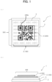
- FIG. 1(a) is a plan view illustrating an information recording medium 1 according to the first embodiment
- FIG. 1(b) is a side view thereof.
- the information recording medium 1 includes a base material 2 and a lustrous ink layer 5 formed by a lustrous ink on one surface of the base material 2.
- a colored ink layer 3 formed with colored ink, and a transparent ink layer 4 formed with transparent ink that has a property of reflecting different amounts of light depending on the observation angle, both partially covering the lustrous ink layer 5, are provided on a surface side of the lustrous ink layer 5 facing opposite to the base material 2.
- the base material 2 has printability and coating suitability for forming the lustrous ink layer 5, the colored ink layer 3, and the transparent ink layer 4. Any film base material is used for supporting these layers.
- the base material 2 include polyester films such as polyethylene terephthalate films, polyethylene films, polypropylene films, polyfluorinated ethylene films, polyvinylidene fluoride films, polyvinyl chloride films, polyvinylidene chloride films, ethylene-vinyl alcohol films, polyvinyl alcohol films, polymethyl methacrylate films, polyethersulfone films, polyether ether ketone films, polyamide films, tetrafluoroethylene-perfluoroalkyl vinyl ether copolymer films, and polyimide films.
- the base material 2 may also be a paper sheet such as paper for use in seals and labels.
- the colored ink constituting the colored ink layer 3 is composed of printing ink used in general design formation printing and the like, and any non-transparent color that allows process colors to be visually recognized as a pattern or design is sufficient.
- the colored ink does not contain lustrous materials.
- the colored ink layer 3 need only camouflage the patterns of overlapping the transparent ink layer 4 to some extent by allowing the colored ink layer 3 itself to be visually recognized or perceived.
- examples of such inks include inks formed by mixing organic or inorganic coloring pigments such as titanium oxide, phthalocyanine, and carbon black into resins such as acrylic, polyester, polyurethane, or epoxy.
- the transparent ink constituting the transparent ink layer 4 can be, for example, a transparent varnish, ink varnish, transparent ink, or medium ink, all of which do not use coloring pigments.
- the transparent ink may be of various types, such as ultraviolet-curable, oxidation-polymerizable, permeable, heat-dryable, or evaporation-dryable.
- the transparent ink layer 4 with such transparent ink has a property such that the ratio of emitted light to incident light varies in the direction of specular reflection, in which the incident angle and the exit angle are substantially equal. In other words, the transparent ink layer 4 reduces the ratio of emitted light to incident light in the direction in which the relationship of the exit angle with respect to the incident angle from the illumination light source is specular reflection.
- the printing methods of forming the lustrous ink layer 5, the colored ink layer 3, and the transparent ink layer 4 may include gravure printing, wet offset printing, dry offset printing, letterpress printing, waterless lithographic printing, flexographic printing, screen printing, intaglio printing, or inkjet printing, and electrostatic printing. Melt transfer or sublimation transfer using an ink ribbon may also be employed.
- the second pattern 200 is a QR code (registered trademark) of Model 2.
- the outer contour of the second pattern 200 is approximately square, and three corners are arranged with finder patterns 200p, each composed of a small square surrounded by a slightly larger outer square.
- the finder patterns also known as position detection patterns, are used to determine the position and orientation of the pattern when read by the reading device.
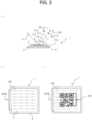
- FIG. 2(a) illustrates a situation where the information recording medium 1 with the pattern image 300 formed thereon is placed on a flat surface (not illustrated) and white light is emitted from an illumination light source 21 arranged at an angle to the direction normal to the main surface of the information recording medium 1.
- the exit angle of the light from the illumination light source 21 is an angle ⁇ with respect to the direction normal to the main surface of the information recording medium 1.
- the pattern image visually recognizable on the information recording medium 1 is the pattern image 300a illustrated in FIG. 2(b) . That is, from the viewpoint 22a at the position P1, where the observation angle is ⁇ 1, only the first pattern 100 is visually recognizable clearly.
- the pattern image visually recognizable on the information recording medium 1 is the same as the pattern image 300a illustrated in FIG. 2(b) . That is, the appearance is similar to that observed from the viewpoint 22a at the position P1, where the observation angle is ⁇ 1. The reason for this is the same as when the observation angle is ⁇ 1.
- the pattern image 300b formed on the information recording medium 1 illustrated in FIG. 2(c) is read by the reading device from the viewpoint 22b at the position P2.
- the reflectance of the light reflected at the portions of the lustrous ink layer 5 that serves as the background of the pattern image 300b and the first pattern 100, with respect to the original white light from the illumination light source 21, is denoted as Re21 (%).
- the reflectance of the light reflected at the second pattern 200, with respect to the original white light from the illumination light source 21, is denoted as Re22 (%).
- the reflectance of the light reflected at the portions of the lustrous ink layer 5 with respect to the white light is denoted as Re211 (%), and the reflectance of the light reflected at the first pattern 100 with respect to the original white light from the illumination light source 21 is denoted as Re212 (%).
- Re211 is greater than Re212.
- Re21 represents the reflectance including both Re211 and Re212.
- the threshold value Re23 of the reflectance for the binarization processing by the reading device is set to be smaller than Re21 and greater than Re22, in which pixels with an incident light reflectance equal to or greater than this threshold value are determined as 1 or white, and pixels with an incident light reflectance below this threshold value are determined as 0 or black.
- the reading device recognizes the portions of the lustrous ink layer 5 serving as the background of the pattern image 300b and the portions of the first pattern 100 as 1 or white, and recognizes the portions of the second pattern 200 as 0 or black. This allows the second pattern 200 to be extracted with good contrast and converted into the specific code accurately.
- the illumination light source 21 is turned off, or the illumination light source 21 is turned on by significantly reducing the light intensity.
- the information recording medium 1 is predominantly illuminated by diffuse light, with no strong parallel light incident, so most of the incident light passes through the transparent ink layer 4.
- the second pattern 200 is not visually recognizable, and only the portions of the lustrous ink layer 5 and the first pattern 100 are visually recognizable due to the effect of diffuse reflection. That is, the pattern image 300a in FIG. 2(b) is visually recognizable.
- the pattern image 300 on the information recording medium 1 can appear in two ways as the pattern images 300a and 300b.
- the same visual effects can be achieved by changing only the light intensity of the illumination light source 21 between an off-state and an on-state, or changing between the on-state at low intensity and the on-state at higher intensity, without changing the positional relationship between the illumination light source 21 and the observation angle.
- the above description holds even when the arrangement of the illumination light source 21 and the observation angle are both aligned with the normal direction in FIG. 2(a) , that is, when both of the angle ⁇ and the angle ⁇ 2 are 0°.
- the first pattern 100 is easily visually recognizable, while the second pattern 200 is difficult to visually recognize unless the incident angle of the light from the illumination light source and the observation angle are in a predetermined relationship. Therefore, the presence of the second pattern 200, which contains information convertible into a specific code, can be kept hidden from third parties, thereby enhancing security. Furthermore, when the pattern image 300 on one surface of the information recording medium 1 is copied using a copier, the illumination light source of the copier differs from the fixed-position constant light irradiation, making it difficult to extract the second pattern 200 formed by the transparent ink layer 4.
- the reading device 30 includes an illumination light source and a two-dimensional code reading function. As illustrated in FIG. 3A , the reading device 30 includes a reading unit 33 such as a camera, the illumination light source 21, an operation unit 35 for various operations, and a display unit 36 that is a display screen for various displays. The reading device 30 includes a control unit 31 for inputting and outputting operation instructions and information for each of these components, and a storage unit 32.
- a reading unit 33 such as a camera
- the illumination light source 21 an operation unit 35 for various operations
- a display unit 36 that is a display screen for various displays.
- the reading device 30 includes a control unit 31 for inputting and outputting operation instructions and information for each of these components, and a storage unit 32.
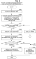
- the reading device 30 activates the reading unit 33, such as a camera (Step S401 in FIG. 4 ).
- the reading device 30 positions the pattern image 300 of the information recording medium 1 within the field of view of the reading unit 33.
- the reading unit 33 can effectively capture the second pattern 200.
- the image acquisition unit 44 acquires the image of the second pattern 200 from the reading unit 33, and the code identification unit 45 converts the image into a specific code (Step S402).
- the illumination light source 21 and the reading unit 33 are provided at substantially the same position in many cases. In this case, the illumination light source 21 and the reading unit 33 should both be positioned to face the direction normal to the main surface of the information recording medium 1.
- the threshold value for binarization processing to extract the two-dimensional code from the captured image is usually automatically adjusted to optimize the reading of the two-dimensional code.
- the threshold value refers to a reference luminance value used to distinguish between the background image that is determined as 1, and the two-dimensional code image that is determined as 0.
- Step S403 and S404 if the conversion to the specific code by the code identification unit 45 is successful, this is displayed on the display unit 36 of the reading device 30 (Steps S403 and S404). On the other hand, if the conversion to the specific code fails, this is also displayed on the display unit 36 (Steps S403 and S408).
- the identified specific code can be considered an authentication number for a financial transaction, allowing the transaction to proceed if the code is deemed authentic.
- the information recording medium 1 may be determined not to be authentic, and the processing can be terminated.
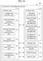
- an authenticity determination device 60 differs from the reading device 30 in that a control unit 31a further includes an authenticity determination unit 46, and a storage unit 32a stores authenticity determination information 53 in addition to the program storage unit 38.
- the authenticity determination unit 46 has the function of determining whether the code converted and identified by the code identification unit 45 from the second pattern 200 in the reading device 30 is authentic through comparison with the authenticity determination information 53 stored in the storage unit 32a. That is, the authenticity determination information 53 serves as comparison information for determining the authenticity of the information recording medium 1.
- a computer refers to an information processing device equipped with a control unit, storage device, and other components
- the authenticity determination device 60 is an information processing device equipped with a control unit 31a, a storage unit 32a, and other components, falling under the concept of a computer.
- the authenticity determination information 53 stored in the storage unit 32a may be a value that matches the code converted from the second pattern 200, or may be a value encrypted with a predetermined encryption key.
- the authenticity determination unit 46 may be equipped with the predetermined encryption key, calculate the value decrypted with its own encryption key from the value of the referenced authenticity determination information 53, and compare this with the code identified from the second pattern 200 to determine authenticity. This reduces the risk of the authenticity determination information 53 being illicitly read or tampered with from outside.
- the authenticity determination device 60 may be composed of a personal computer or server equipped with the functions of the control unit 31a and the storage unit 32a, a CCD camera being the reading unit 33, the illumination light source 21, the operation unit 35, and the display unit 36. Each device may be communicatively connected to each other via cables, or may be communicatively connected to each other via a network such as the Internet. In this case, the authenticity determination device 60 constitutes an authenticity determination system where each device is communicatively connected to each other.
- the authenticity determination device 60 may also be a device integrated with the aforementioned functions, such as a smartphone.
- the stacked configuration of the information recording medium 1a according to the second embodiment, illustrated in FIG. 5(a) is the same as the stacked configuration of the information recording medium 1 according to the first embodiment illustrated in FIG. 1(b) .
- the information recording medium 1a includes a pattern image 301 superimposed on the lustrous ink layer 5 on one surface side of the base material 2.
- the pattern image 301 includes a first pattern 101 formed by the colored ink layer 3 and a second pattern 200 formed by the transparent ink layer 4.
- the first pattern 101 constituting the pattern image 301 is not a pattern composed of characters or the like, but both the first pattern 101 and the second pattern 200 are two-dimensional codes, which differs from the first embodiment.
- a general reading device equipped with a two-dimensional code reading function can individually read both the first pattern 101 and the second pattern 200 and convert them into unique specific codes.
- the transparent ink constituting the second pattern 200 is preferably difficult to visually recognize, and the alignment when reading with a machine (e.g., a camera) is executed while visually checking the first pattern 101 that is easily visually recognizable. With this configuration, alignment can be easily executed while visually checking through the machine.
- a machine e.g., a camera
- the colored ink layer 3 constituting the first pattern 101 may have the same configuration as in the first embodiment, and the colored ink used to form the colored ink layer 3 is preferably formed as halftone dots with a halftone dot area ratio between 35% and 55% inclusive, and more preferably formed as halftone dots with a halftone dot area ratio between 40% and 50% inclusive. This is because the same effects as in the first embodiment can be expected even when the first pattern 101 is a two-dimensional code.
- both the first pattern 101 and the second pattern 200 are QR codes (registered trademark) of Model 2.
- both of the patterns have an approximately square outer contour, and finder patterns 101p and 200p, each composed of a small square surrounded by a slightly larger square outer frame, are arranged at three corners.
- the two patterns are preferably arranged such that the finder patterns 101p of the first pattern 101 do not overlap with the second pattern 200. This improves the readability of the first pattern 101.
- the following describes a situation where the information recording medium 1a with the pattern image 301 formed thereon is placed on a flat surface (not illustrated), and white light is emitted from an illumination light source 21 arranged at an angle to the direction normal to the main surface of the information recording medium 1a.
- the pattern image visually recognizable on the information recording medium 1 is the pattern image 301a illustrated in FIG. 5(b) .
- the appearance is similar to that observed from the viewpoint 22a at the position P1, where the observation angle is ⁇ 1.
- the pattern image 301a formed on the information recording medium 1 illustrated in FIG. 5(b) is read by a two-dimensional code reading device from the viewpoint 22a at the position P1 or the viewpoint 22c at the position P3.
- the reflectance of the light reflected at the lustrous ink layer 5 that serves as the background of the pattern image 301a, with respect to the original white light from the illumination light source 21, is denoted as Re211 (%).
- the reflectance of the light reflected at the first pattern 101, with respect to the original white light from the illumination light source 21, is denoted as Re212 (%). That is, the same definitions as in the first embodiment apply.
- the reading device executes binarization processing for each pixel, based on the amount of incident light on the CCD elements.
- the first threshold value Re13 is set to be greater than Re212 and smaller than Re211, in which pixels with an incident light reflectance equal to or greater than this threshold value are determined as 1 or white, and pixels with an incident light reflectance below this threshold value are determined as 0 or black.
- the reading device recognizes the portions of the lustrous ink layer 5 serving as the background of the pattern image 300a as 1 or white, and recognizes the portions of the first pattern 101 as 0 or black, thereby allowing the first pattern 101 to be extracted with good contrast and converted into a specific code accurately.
- the lustrous ink layer 5 is slightly exposed through the gaps of the first pattern 101 that serves as the background of the pattern image 301b, as described above, the cell size of the two-dimensional code in the first pattern 101 is sufficiently small, minimizing the risk of the lustrous ink layer 5 hindering the reading of the second pattern 200.
- the foregoing has described that the pattern image 301 appears in two ways as the pattern image 301a or 301b, depending on the relationship between the position of the illumination light source 21 and the observation angle; however, such differences in appearance can be created even without changing the relationship between the position of the illumination light source 21 and the observation angle. This aspect is similar to the first embodiment.
- the first pattern 101 is easily visually recognizable, while the second pattern 200 is difficult to visually recognize, whereby the presence of the second pattern 200, which contains information convertible into a specific code, can be kept hidden from third parties, thereby enhancing security.
- the illumination light source of the copier differs from the fixed-position constant light irradiation, making it difficult to extract the second pattern 200 formed by the transparent ink layer 4.
- the first pattern 101 composed of the colored ink layer 3 on the diffusely reflecting portions of the underlying lustrous ink layer 5, is likely to be extracted. This achieves an anti-copying effect, making it difficult to replicate the information recording medium 1a, which further improves security.
- both the first pattern 101 and the second pattern 200 which constitute the pattern image 301, are patterns that can be read by a general reading device equipped with a two-dimensional code reading function under predetermined conditions and can each be converted into a unique specific code.
- the first pattern 101 is provided solely for camouflage, and the specific code converted from the first pattern 101 may be a meaningless dummy code.
- the second pattern 200 can be read under predetermined conditions, converted into a specific code, or used for authenticity determination.
- the reading device may be configured to read the first pattern 101 constituting the pattern image 301 under a predetermined first condition, and to read the second pattern 200 constituting the pattern image 301 under a predetermined second condition.
- the predetermined first condition may be when the illumination of the reading device is turned off
- the predetermined second condition may be when the illumination of the reading device is turned on.
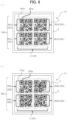
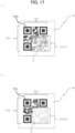
- the information recording medium 1b according to the third embodiment, illustrated in FIG. 6(a) includes a pattern image 302 superimposed on the lustrous ink layer 5 on one surface side of the base material 2.
- the pattern image 302 includes a first pattern 101 formed by the colored ink layer 3 and a second pattern 201 formed by the transparent ink layer 4.
- the second pattern 201 which is formed by the transparent ink layer 4 on the information recording medium 1b, consists of a plurality of partial patterns 201a, 201b, 201c, and 201d, which are separately arranged at four locations: the upper left, upper right, lower left, and lower right.
- This aspect differs from the information recording media 1 and 1a of the first and second embodiments.
- Each partial pattern is arranged in a matrix of two vertical columns and two horizontal rows.
- all four partial patterns constituting the second pattern 201 are the two-dimensional codes of the same pattern. That is, when a general reading device equipped with a two-dimensional code reading function can separately read each of the partial patterns constituting the first pattern 101 and the second pattern 201, the reading device can convert the patterns into unique specific codes.
- the partial patterns 201a, 201b, 201c, and 201d are each converted into the same code.
- the four partial patterns are arranged at predetermined intervals so as to be oriented in the same direction.
- the finder patterns 201p of the plurality of partial patterns are arranged so as not to overlap with each other, with the finder patterns 201p being arranged at the upper left, upper right, and lower left of each partial pattern.
- the information recording medium 1b of the third embodiment incorporates all the features of the information recording media 1 and 1a of the first and second embodiments, while also including the second pattern 201 that is formed by the transparent ink layer 4 and consists of a plurality of partial patterns separately arranged at four locations. Furthermore, each partial pattern is converted into the same code.
- This configuration of the information recording medium 1b can improve the quality of the information recording medium 1b and enhance the adaptability to different reading environments.
- halation may arise in part of the second pattern 201.
- the correct specific code can be decoded. Therefore, the reading conditions of the reading device can be relaxed while still ensuring accurate authenticity determination.
- the configuration of the information recording medium 1c according to the fourth embodiment, illustrated in FIG. 6(b) , is almost identical to that of the information recording medium 1b according to the third embodiment.
- the information recording medium 1c includes a pattern image 303 superimposed on the lustrous ink layer 5 on one surface side of the base material 2.
- the pattern image 303 includes a first pattern 101 formed by the colored ink layer 3 and a second pattern 202 formed by the transparent ink layer 4.
- the second pattern 202, formed by the transparent ink layer 4 on the information recording medium 1c consists of different partial patterns, with each partial pattern capable of being converted into a different specific code, which is distinguished from the third embodiment.
- the reading device 30a differs from the reading device 30 in that the reading device 30a includes a storage unit 32b, and the storage unit 32b stores first pattern position identification information 51 and second pattern position identification information 52, in addition to the program storage unit 38.
- the reading device 30a also differs from the reading device 30 in the following.
- the control unit 31b includes a first pattern position identification unit 42 that identifies the position and range for reading the first pattern 101 by referencing the first pattern position identification information 51 in the storage unit 32b.
- the control unit 31b includes a second pattern position identification unit 43 that identifies the position and range for reading the second pattern 202 by referencing the second pattern position identification information 52.
- the storage of the first pattern position identification information 51 is optional, and is applicable to a case where the first pattern 101 of the information recording medium 1c is separately arranged at the plurality of partial patterns, each of which is convertible into a different specific code.
- the first pattern position identification information 51 includes the arrangement information of the partial pattern containing the authentic code. In the present embodiment, this information may not be necessary, since the first pattern 101 is convertible into a single code.
- the second pattern position identification information 52 includes the arrangement information of the partial pattern containing the authentic code among the plurality of partial patterns constituting the second pattern 202 of the information recording medium 1b. For example, the information indicates that the partial pattern 202a arranged in the upper left is authentic.
- the reading device 30a may be composed of, for example, a personal computer or server equipped with the functions of the control unit 31b and the storage unit 32b, a CCD camera being the reading unit 33, the illumination light source 21, the operation unit 35, and the display unit 36. Each device may be communicatively connected to each other via cables, or may be communicatively connected to each other via a network such as the Internet.
- the reading device 30a may also be a device integrated with the aforementioned functions, such as a smartphone.
- the reading device 30a activates the reading unit 33, such as a camera (Step S421 in FIG. 8 ).
- the reading device 30a sets the pattern image 303 of the information recording medium 1c within the field of view of the reading unit 33.
- the control unit 31b references this information, and the first pattern position identification unit 42 identifies the position and range of the first pattern 101 that needs to be read within the pattern image 303 by the reading unit 33 (Step S422).
- this operation is unnecessary since the first pattern 101 is a single two-dimensional code, and the finder pattern 101p can be used to identify the position and range for reading the first pattern 101.
- the illumination control unit 41 of the reading device 30a turns off the illumination light source 21, such that the reading unit 33 can capture only the first pattern 101 from the pattern image 303 of the information recording medium 1c.
- the illumination light source 21 By turning off the illumination light source 21, no intense parallel light is incident on the information recording medium 1b from a specific direction, and the information recording medium 1c predominantly receives diffuse light overall.
- the reading unit 33 the light reflected from the lustrous ink layer 5 of the information recording medium 1c increases relative to the light reflected from the colored ink layer 3, thus the contrast between the lustrous ink layer 5 and the first pattern 100 of the colored ink layer 3 becomes clear. This allows only the first pattern 101 to be captured well.
- the image acquisition unit 44 acquires the image of the first pattern 100 from the reading unit 33, and the code identification unit 45 converts the image into a specific code (Step S423).
- the state in which the reading unit 33 can capture only the first pattern 101 from the pattern image 303 of the information recording medium 1c is not limited to the case where the illumination light source 21 is turned off.
- such a state is also feasible in a case where the illumination light source 21 is turned on by significantly reducing the light intensity.
- Steps S424 and S425 if the conversion to the specific code by the code identification unit 45 is successful, this is displayed on the display unit 36 of the reading device 30a (Steps S424 and S425). On the other hand, if the conversion to the specific code fails, this is also displayed on the display unit 36 (Steps S424 and S426). In the former case, the processing proceeds to processing B, where the position and range for reading the second pattern 202 are identified based on the code identified from the first pattern 101. In the latter case, the processing proceeds to processing C.
- the illumination control unit 41 of the reading device 30a turns on the illumination light source 21 such that the reading unit 33 can capture only the second pattern 202 from the pattern image 303 of the information recording medium 1c.
- the reading unit 33 can receive the specular reflection light from the information recording medium 1c.
- the light reflected from the transparent ink layer 4 of the information recording medium 1c is reduced compared to the light reflected from the lustrous ink layer 5 and the colored ink layer 3.
- the contrast becomes clear between the second pattern 202 formed by the transparent ink layer 4 and the background consisting of the portions of the lustrous ink layer 5 and the first pattern 101 formed by the colored ink layer 3.
- the reading unit 33 can capture the second pattern 202 clearly.
- the image acquisition unit 44 acquires the image of the partial pattern 202a from the second pattern 202 through the reading unit 33, and the code identification unit 45 converts the image into a specific code (Step S442).
- Steps S443 and S444 If the conversion to the specific code by the code identification unit 45 is successful, this is displayed on the display unit 36 of the reading device 30a (Steps S443 and S444). On the other hand, if the conversion to the specific code fails, this is also displayed on the display unit 36 (Steps S443 and S445). In the former case, the other processing as described above can be continued based on the code identified from the partial pattern 202a of the second pattern 202.
- the authenticity determination device 60a differs from the authenticity determination device 60 in that the authenticity determination device 60a includes a storage unit 32c, and the storage unit 32c stores the first pattern position identification information 51 and the second pattern position identification information 52, in addition to the program storage unit 38 and the authenticity determination information 53.
- the control unit 31c includes a first pattern position identification unit 42 that identifies the position and range for reading the first pattern 101 by referencing the first pattern position identification information 51 in the storage unit 32c.
- control unit 31c includes a second pattern position identification unit 43 that identifies the position and range for reading the second pattern 202 by referencing the second pattern position identification information 52.
- the storage unit 32c stores the authenticity determination information 53 as comparative information for determining the authenticity of the information recording medium 1b.
- the authenticity determination device 60a may be composed of, for example, a personal computer or server equipped with the functions of the control unit 31c and the storage unit 32c, a CCD camera being the reading unit 33, the illumination light source 21, the operation unit 35, and the display unit 36. Each device may be communicatively connected to each other via cables, or may be communicatively connected to each other via a network such as the Internet. In this case, the authenticity determination device 60a constitutes an authenticity determination system, in which each device is communicatively connected to each other.
- the authenticity determination device 60a may also be a device integrated with the aforementioned functions, such as a smartphone.
- the authenticity determination device 60a executes the steps from activating the reading unit 33 (Step S421 in FIG. 8 ) to identifying the code by reading the first pattern 101 (Step S424), and displays the result (Step S425). This is similar to the method of identifying the code from the first pattern 101 by the reading device 30a.
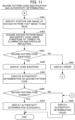
- the authenticity determination device 60a executes Steps S461 to S464 as illustrated in FIG. 11 , corresponding to Steps S441 to S444 for the reading device 30a as illustrated in FIG. 9 .
- the authenticity determination unit 46 determines the authenticity of the code identified from the partial pattern 202a by the code identification unit 45 (Step S466). If the code is determined to be authentic, this is displayed (Step S467), or if the code is determined not to be authentic, this is also displayed (Step S469), and the processing ends. If the first pattern 101 could not be converted into a specific code (Step S424 and Step S426 in FIG. 8 ) and the processing did not proceed to the step of identifying the code of the second pattern 202, the processing also ends after executing Step S469.
- the information recording medium 1c of the fourth embodiment can be read such that the first pattern 101 formed by the colored ink layer 3 is convertible into a specific code.
- the second pattern 202 formed by the transparent ink layer 4 consists of four partial patterns 202a, 202b, 202c, and 202d, each of which can be read so as to be convertible into a specific code. Furthermore, at least one of these partial patterns is convertible into a code different from the others.
- the first pattern 101 is convertible into the first specific code
- the specific partial pattern 202a is convertible into the second specific code.
- the first specific code includes information on the position and range of the specific partial pattern 202a whose code should be identified, within the second pattern 202.
- the first specific code can be first extracted by reading the first pattern 100, then the position and range of the specific partial pattern 202a to be read within the second pattern 202 can be identified based on the code, and the second specific code can be extracted from the specific partial pattern 202a.
- the second specific code may be any one of the partial patterns 202a to 202d, or may be a combination of codes read from the plurality of partial patterns.
- the first pattern 101 and the second pattern 202 are difficult to correctly read separately. Furthermore, even if the first pattern 101 and all of the four partial patterns of the second pattern 202 are read using a general-purpose reading device, it is difficult to determine which of the codes identified from these patterns represents the authenticity of the information recording medium 1b. This enhances the security provided by the information recording medium 1c.
- the information recording medium 1d according to the fifth embodiment, illustrated in FIG. 12(a) includes a pattern image 304 superimposed on the lustrous ink layer 5 on one surface of the base material 2.
- the pattern image 304 includes a first pattern 101 formed by the colored ink layer 3 and a second pattern 203 formed by the transparent ink layer 4.
- the configuration of the information recording medium 1d is almost identical to the first pattern 101 and the information recording medium 1b of the third embodiment, except that the orientation of the plurality of partial patterns, separately arranged at four locations of the second pattern 203 formed by the transparent ink layer 4, differs from that of the second pattern 201.
- the partial pattern 203c is arranged as rotated 90° counterclockwise relative to the partial pattern 203a.
- the partial pattern 203d is arranged as rotated 180° clockwise or counterclockwise relative to the partial pattern 203a. Consequently, the partial pattern 203a is arranged with the finder patterns 203p at the top left, top right, and bottom left thereof, while the partial pattern 203b is arranged with the finder patterns 203p at the top left, top right, and bottom right thereof.
- each partial pattern has three finder patterns 203p, but this can also be applied to a case where each partial pattern has only one finder pattern.
- the finder pattern of the top left partial pattern is arranged at the top left
- the finder patterns of the top right, bottom left, and bottom right partial patterns are positioned at the top right, bottom left, and bottom right, respectively.
- the information recording medium 1e according to the sixth embodiment, illustrated in FIG. 12(b) includes a pattern image 305 superimposed on the lustrous ink layer 5 on one surface of the base material 2.
- the pattern image 305 includes a first pattern 101 formed by the colored ink layer 3 and a second pattern 204 formed by the transparent ink layer 4.
- the configuration of the information recording medium 1e is similar to that of the information recording medium 1d according to the fifth embodiment, except that the second pattern 204 formed by the transparent ink layer 4 includes a plurality of partial patterns separately arranged at nine locations, rather than four.
- the finder patterns 204p of the partial patterns arranged at the four corners of the second pattern 204 are arranged at the edges along the outer perimeter of the second pattern 204.
- This configuration of the information recording medium 1e can further improve the quality of the information recording medium 1e and further enhance the adaptability to various reading environments.
- the information recording medium 1f according to the seventh embodiment, illustrated in FIG. 13 includes a pattern image 306 superimposed on the lustrous ink layer 5 on one surface of the base material 2.
- the pattern image 306 includes a first pattern 101 formed by the colored ink layer 3 and a second pattern 205 formed by the transparent ink layer 4.
- the configuration of the information recording medium 1f is similar to that of the information recording medium 1e according to the sixth embodiment.
- the second pattern 205 formed by the transparent ink layer 4 includes partial patterns arranged at the four corners.
- the second pattern 205 includes a total of nine partial patterns including: four partial patterns interposed between the first and second partial patterns, sharing the finder patterns 205p; and a partial pattern arranged at the center (third partial pattern).
- the partial patterns 205a, 205c, 205g, and 205i are arranged at the corners of the substantially square second pattern 205, specifically at the top left, top right, bottom left, and bottom right corners, respectively. Furthermore, dummy patterns, which cannot be converted into specific codes or are not intended to be converted, are embedded between the partial patterns 205a and 205c, between 205a and 205g, between 205c and 205i, and between 205g and 205i. These dummy patterns share the finder patterns 205p of the partial patterns arranged to the left, right, or above and below, thereby forming dummy partial patterns that artfully disguise as a two-dimensional code.
- dummy partial patterns 205b, 205d, 205f, and 205h are formed between the partial patterns 205a and 205c, 205a and 205g, 205c and 205i, and 205g and 205i, respectively.
- a dummy partial pattern 205e is also embedded in the center, surrounded by the partial patterns 205a, 205c, 205g, and 205i.
- the partial patterns 205a, 205c, 205g, and 205i of the second pattern 205 are convertible into specific codes, with 205c, 205g, and 205i being convertible into the same specific code, while 205a is convertible into a different specific code.
- the second pattern 205 of the information recording medium 1f appears to include nine partial patterns.
- the partial patterns 205a, 205c, 205g, and 205i arranged at the four corners are two-dimensional codes convertible into specific codes, while the others are merely dummy partial patterns that cannot be converted into specific codes.
- the four partial patterns include patterns convertible into different specific codes, with only the partial pattern 205a being convertible into an authentic specific code.
- the information recording medium 1g according to the eighth embodiment, illustrated in FIG. 14 includes a pattern image 308 superimposed on the lustrous ink layer 5 on one surface of the base material 2.
- the pattern image 308 includes a first pattern 102 formed by the colored ink layer 3 and a second pattern 208 formed by the transparent ink layer 4.
- the configuration of the information recording medium 1g is similar to that of the information recording medium 1f according to the seventh embodiment.
- the second pattern 208 formed by the transparent ink layer 4 appears to be two-dimensional codes arranged in a matrix of three vertical columns and five horizontal rows, consisting of a plurality of partial patterns and dummy partial patterns.
- a dummy partial pattern 208a, a partial pattern 208b, a dummy partial pattern 208c, a partial pattern 208d, and a dummy partial pattern 208e are sequentially arranged from left to right.
- a dummy partial pattern 208k, a partial pattern 208l, a dummy partial pattern 208m, a partial pattern 208n, and a dummy partial pattern 208o which are sequentially arranged from left to right in the third row.
- the second pattern 208 of the information recording medium 1g appears to include fifteen partial patterns.
- the partial patterns in the second and fourth columns from the left are convertible into specific codes, while the rest are composed of meaningless dummy patterns.
- some or all of the six partial patterns convertible into specific codes are converted into different codes, thereby making it even more difficult to extract and correctly read only the authentic code.
- only the partial pattern 208b is convertible into the authentic code.
- both the first and second patterns are two-dimensional codes.
- the first and second patterns of the information recording medium according to the present disclosure are not limited to two-dimensional codes; a case where at least the second pattern contains information convertible into a specific code by a reading device is applicable.
- the ninth embodiment, where the first and second patterns are barcodes, and the tenth embodiment, where the first and second patterns are alphanumeric characters, will be briefly described.
- Printed material including an information recording medium refers to, for example, tickets or admission passes for movies, concerts, amusement parks, etc., or cards, to which the information recording medium is attached.
- Printed material including an information recording medium has monetary value in itself, but copies made by color photocopying or similar means naturally do not have any monetary value.
- An example of the printed material including the information recording medium may include the printed material 10 being an admission pass illustrated in FIG. 16(a) .
- the printed material 10 includes a sheet 11 and the information recording medium 1 of the first embodiment, where part of the sheet 11 is regarded as the base material 2.
- the sheet 11 has a printed portion 12 formed with printed information indicating the type of ticket, purchaser, serial number, etc.
- the sheet 11 is the base material of the printed material 10 and is typically a white paper sheet, but may be high-quality paper or coated paper as well, and may also be made of plastic other than paper. Alternatively, the sheet may be a composite or stacked material of paper and plastic. In any case, the sheet 11 need only be capable of supporting the information recording medium 1 and carrying various printed designs indicating ticket types, etc.
- the printed material including the information recording medium is particularly difficult to forge or misuse through copying with a photocopier. This is more cost-effective in terms of materials and processing, and easier to deploy, as compared to holograms with equivalent anti-counterfeiting effects.
- a general-purpose two-dimensional code reading device it is possible to easily read specific codes and execute authenticity determination while maintaining high security, thereby improving convenience.
- the printed material including the information recording medium of the present embodiment is also applicable to cases of replacement with any one of the information recording media according to the embodiments other than the first embodiment or the modifications thereof.
- the feature described in the first embodiment is common to all the second through eleventh embodiments, where the first pattern of the information recording medium is easily visually recognizable, but the second pattern is difficult to visually recognize, and the presence of the second pattern containing information convertible into a specific code is difficult for a third party to recognize, thereby enhancing security.
- the first pattern 111 alone cannot be read as a specific code, but can be read as a specific code when read together with the basic pattern 511 as a whole.
- the basic pattern 511 and the first pattern 111 form, for example, a two-dimensional code as a whole. While the first region was described as having the basic pattern 511 directly formed on the base material 2 using colored ink or the like, the same configuration as the second region can also be applied, where the lustrous ink layer 5 is formed on one surface of the base material 2, and the basic pattern 511 is formed thereon using black or other colored inks.
- another information recording medium 1p has a third region and a fourth region on one surface of the base material 2, with the entire surface forming a pattern image 312.
- a basic pattern 512 is formed on one surface of the base material 2 using, for example, black-colored ink.
- the basic pattern 512 is configured in a manner similar to that of the information recording medium 1n as described above.
- a lustrous ink layer 5 is formed on one surface of the base material 2, and a second pattern 212 is formed thereon using the transparent ink layer 4 without interposing a colored ink layer or other layers.
- the conditions of the lustrous ink layer 5, the colored ink layer 3, and the transparent ink layer 4 in this case are the same as those described in the first embodiment.
- the second pattern 212 alone cannot be read as a specific code, but can be read as a specific code when read together with the basic pattern 512 as a whole.
- the basic pattern 512 and the second pattern 212 together form, for example, a two-dimensional code as a whole.
- the reading and authenticity determination using these two types of information recording media 1n and 1p can be executed as follows.
- the illumination light source of the reading device is turned off, and the pattern image 311 of the information recording medium 1n is read.
- the basic pattern 511 in the first region and the first pattern 111 in the second region correspond to the conditions where the incident angle and the observation angle of the illumination light source result in diffuse reflection.
- each pattern achieves good contrast with the underlying base material 2 or the lustrous ink layer 5, allowing the patterns to be read together as one specific code that is a composite of the patterns.
- the illumination light source of the reading device is turned on, and the pattern image 312 of the information recording medium 1p is read.
- the basic pattern 512 in the third region and the second pattern 212 in the fourth region correspond to the conditions where the incident angle and the observation angle of the illumination light source result in specular reflection.
- each pattern achieves good contrast with the underlying base material 2 or the lustrous ink layer 5, allowing the patterns to be read together as one specific code that is a composite of the patterns.
- Up-conversion luminescent material Materials that emit visible light when excited by infrared radiation are also known as up-conversion luminescent material. Examples include materials containing at least one rare-earth element selected from the group consisting of erbium (Er), holmium (Ho), praseodymium (Pr), thulium (Tm), neodymium (Nd), gadolinium (Gd), europium (Eu), samarium (Sm), terbium (Tb), dysprosium (Dy), and cerium (Ce), with the base material of the phosphor particles being a halide or the like. Some of these materials overlap with those disclosed in Japanese Unexamined Patent Application, Publication No. 7-297475 .
- the ink used to form the transparent ink layer 4j of the information recording medium 1j with a transparent material ink that emits visible light when excited by infrared or ultraviolet radiation, the following effects can be achieved. Specifically, the accuracy of the anti-counterfeiting function of the present disclosure, which utilizes the difference in appearance between the first pattern 100 composed of the colored ink layer 3 and the second pattern 200 composed of the transparent ink layer 4j due to the relationship between the illumination angle and the observation angle of visible light, can be improved and supplemented.
- the visibility of the transparent ink layer 4j can be enhanced only when irradiated with infrared or ultraviolet radiation in a specific wavelength range, almost without being affected by the lustrous ink layer 5 or the colored ink layer 3. This ensures even greater difficulty in reading and duplicating the pattern.
- the transparent material ink may also be configured by mixing both materials that emit visible light when excited by infrared radiation and materials that emit visible light when excited by ultraviolet radiation. This allows the visibility of the transparent ink layer 4j to be improved with any one of the two types of invisible light, thereby enhancing convenience.
- the transparent ink layer 4j emits visible light by irradiating the transparent ink layer 4j with infrared or ultraviolet radiation during or after forming the transparent ink layer 4j, whereby the presence of the second pattern 200 can be easily confirmed. Therefore, this contributes to quality improvement of the information recording medium 1j.
- the transparent ink layer 4k by irradiating the transparent ink layer 4k with infrared radiation in a specific wavelength range during or after forming the transparent ink layer 4k, the state of absorbing or reflecting the infrared radiation can be visualized through an infrared camera or the like. Therefore, the formation state of the transparent ink layer 4k, which is difficult to visually confirm with the naked eye, can be easily checked through an infrared camera or the like, contributing to improving the quality of the information recording medium 1k.
- the polarizer solution is applied over the alignment film to a predetermined thickness using the micro-gravure method, thereby forming a coating film.
- annealing treatment is executed on the coating film, followed by UV irradiation in an oxygen atmosphere to cure the coating film, thereby forming the transparent ink layer 4m, including the polarizing function with a transmission axis aligned in a predetermined direction.
- a laser with a specific wavelength can be used to irradiate the areas without pattern images to thermally disrupt the liquid crystal molecules in the areas, thereby imparting the polarizing function only to the areas with pattern images.
- effects similar to those of the first and second modifications can be achieved by configuring the ink used to form the transparent ink layer 4m of the information recording medium 1m with a transparent material ink containing a polarizing material.
- the visibility of the transparent ink layer 4m can be enhanced only when a specific polarizing film is used, almost without being affected by the lustrous ink layer 5 or the colored ink layer 3. This ensures even greater difficulty in reading and duplicating the pattern.
- the authenticity determination device 60 which executes the authentication of the information recording medium 1 described in the first embodiment, can fulfill the functions of the authenticity determination device 60 by causing the control unit 31a to execute a predetermined program.
- a program executed by the computer of the authenticity determination device 60, reads the information of the first pattern of the information recording medium when the illumination light source is turned on at the first light intensity including the off-state, and converts the read information of the first pattern into a first specific code.
- the program identifies the position of reading the second pattern, reads the information of the second pattern of the information recording medium when the illumination light source is turned on at the second light intensity greater than the first light intensity, and converts the read information of the second pattern into a second specific code.
- the program compares the second specific code with comparison information for authenticity determination, determines that the information recording medium is authentic in a case where the codes match, and determines that the information recording medium is not authentic in a case where the codes do not match.
Landscapes
- Physics & Mathematics (AREA)
- Health & Medical Sciences (AREA)
- General Health & Medical Sciences (AREA)
- Toxicology (AREA)
- General Physics & Mathematics (AREA)
- Spectroscopy & Molecular Physics (AREA)
- Engineering & Computer Science (AREA)
- Computer Security & Cryptography (AREA)
- Printing Methods (AREA)
- Credit Cards Or The Like (AREA)
Abstract
Description
- The present invention relates to an information recording medium that is difficult to counterfeit, and an anti-counterfeiting printed material that includes such an information recording medium.
- Conventionally, electronic watermark technology has been used, in which information that cannot be visually recognized by the human eye is embedded in printed materials and the like. This technology allows the embedded information to be read by a reading device without compromising the aesthetic appearance of the printed material.
-
Patent Document 1 discloses a printed material utilizing electronic watermark technology, in which an information recording medium is provided with a composite image including an image printed on a lustrous layer and another image formed on the image and printed as a transparent layer. With this information recording medium, the two images are printed with inks that reflect different amounts of light in accordance with the observation angle, allowing one of the images of the composite image to be recognized depending on the observation angle. The image printed on the lustrous layer is an image with regularity in the feature points in the spatial frequency domain, while the other image printed on the transparent layer is an image where the feature points in the spatial frequency domain are arranged in positions that disrupt this regularity. - Patent Document 1:
Japanese Unexamined Patent Application, Publication No. 2016-93895 - In this case, by adjusting the observation angle of a dedicated reading device, the image information printed on the lustrous layer of the printed material, which has regularity in the feature points in the spatial frequency domain, can be read and decoded. However, in order to decode the information embedded using electronic watermark technology, the reading device generally needs to be equipped with a decoding application program with a dedicated algorithm, which could make it difficult to easily use a general-purpose reading device such as a smartphone. Furthermore, the appearance of the image information to be read on the printed material is difficult to visually recognize, making it hard to visually determine where to read the image information, which could affect convenience. On the other hand, examples of codes that can be read by general-purpose reading devices include OCR characters, barcodes, or two-dimensional codes. However, these codes are easily duplicated or counterfeited, and using such codes as-is may cause problems in determining the authenticity or ensuring the security of the printed material.
- The present disclosure has been made in view of such circumstances, and aims to provide an information recording medium and a printed material that are easy to read and decode with general-purpose reading devices and are difficult to duplicate or counterfeit, and a reading device for the information recording medium.
- The information recording medium according to an embodiment of the present disclosure includes: a base material; a first printed layer formed by a lustrous ink on one surface of the base material; a second printed layer formed by a colored ink that is not a lustrous ink, on the same side as the one surface; and a third printed layer formed by a transparent ink on the same side as the one surface, in which the second printed layer forms a first pattern, the third printed layer forms a second pattern, in a plan view, an entire region of the first pattern and the second pattern overlaps with a region where the first printed layer is formed, and the second pattern includes information convertible into a specific code, with at least part thereof overlapping with the first pattern.
- In the information recording medium according to another embodiment of the present disclosure, the first printed layer may be formed either as a solid print, halftone dots with a halftone dot area ratio of 80% or more, or lines.
- In the information recording medium according to another embodiment of the present disclosure, the second pattern may be composed of a plurality of partial patterns.
- In the information recording medium according to another embodiment of the present disclosure, only part of the plurality of partial patterns may include information convertible into the specific code.
- In the information recording medium according to another embodiment of the present disclosure, the second pattern may be composed of a plurality of partial patterns, each including one or more finder patterns, and all of the finder patterns may be two-dimensional codes arranged at edges of the second pattern.
- In the information recording medium according to another embodiment of the present disclosure, the second pattern may be composed of a plurality of partial patterns, and when the plurality of partial patterns are defined as a first partial pattern, a second partial pattern, and a third partial pattern sandwiched between the first and second partial patterns, a first finder pattern arranged on a side of the first partial pattern facing the second partial pattern and a second finder pattern arranged on a side of the second partial pattern facing the first partial pattern may compose at least two finder patterns of the third partial pattern, and the third partial pattern may compose dummy information inconvertible into the specific code.
- In the information recording medium according to another embodiment of the present disclosure, the first pattern may include information convertible into a specific code different from the specific code of the second pattern.
- In the information recording medium according to another embodiment of the present disclosure, the third printed layer may be composed of the transparent ink that emits visible light when excited by infrared or ultraviolet radiation, an ink containing an infrared-absorbing material, or an ink containing a polarizing material.
- The printed material according to another embodiment of the present disclosure may include the information recording medium according to any one of the aforementioned embodiments.
- A reading device that reads the information recording medium according to any one of the aforementioned embodiments of the present disclosure includes: an illumination light source; a reading unit; and a control unit, in which the reading unit is capable of reading information of the first pattern of the information recording medium by turning on the illumination light source at a first light intensity including an off-state, and is capable of reading information of the second pattern by turning on the illumination light source at a second light intensity greater than the first light intensity, and the control unit activates the reading unit, turns on the illumination light source at the second light intensity while the reading unit is in a readable state, causes the reading unit to read the information of the second pattern while the illumination light source is turned on, and converts the information of the second pattern read by the reading unit into the specific code.
- An authenticity determination device including the reading device according to an embodiment of the present disclosure further includes: a storage unit that stores comparison information for determining authenticity of the information recording medium; and an authenticity determination unit that compares the specific code with the comparison information, and determines that the information recording medium is authentic when both match, or determines that the information recording medium is not authentic when both do not match.
- In the reading device according to another embodiment of the present disclosure, the reading unit is capable of reading information of the first pattern of the information recording medium by turning on the illumination light source at a first light intensity including an off-state, and information of the second pattern by turning on the illumination light source at a second light intensity greater than the first light intensity. When the specific code is defined as a second specific code, the code identification unit may further include a position identification unit that converts the information of the first pattern and the second pattern read by the reading unit into a first specific code and the second specific code, respectively, and identifies a position of reading the second pattern by the first specific code.
- The authenticity determination device according to another embodiment of the present disclosure may further include: a storage unit that stores comparison information for determining authenticity of the information recording medium; and an authenticity determination unit that compares the second specific code with the comparison information, and determines that the information recording medium is authentic when both match, or determines that the information recording medium is not authentic when both do not match.
- An authenticity determination system according to another embodiment of the present disclosure is an authenticity determination system, in which the reading device and a server are communicatively connected to each other, and the server may include: a storage unit that stores comparison information for determining authenticity of the information recording medium; and an authenticity determination unit that compares the second specific code read by the reading device with the comparison information, and determines that the information recording medium is authentic when both match, or determines that the information recording medium is not authentic when both do not match.
- A method for reading the information recording medium according to an embodiment of the present disclosure includes the steps of: reading the information of the first pattern of the information recording medium that can be read by turning on the illumination light source at a first light intensity including an off-state; converting the read information of the first pattern into a first specific code; identifying a position for reading the second pattern based on the first specific code; reading the information of the second pattern of the information recording medium that can be ready by turning on the illumination light source at a second light intensity greater than the first light intensity; and converting the read information of the second pattern into a second specific code.
- A program for causing a computer to determine the authenticity of the information recording medium according to an embodiment of the present disclosure may read the information of the first pattern of the information recording medium when the illumination light source is turned on at a first light intensity including an off-state, convert the read information of the first pattern into a first specific code, identify the position for reading the second pattern based on the first specific code, read the information of the second pattern of the information recording medium when the illumination light source is turned on at a second light intensity greater than the first light intensity, convert the read information of the second pattern into a second specific code, compare the second specific code with comparison information for authenticity determination, and determine that the information recording medium is authentic when both match, or determine that the information recording medium is not authentic when both do not match.
- A method for determining the authenticity of the information recording medium according to an embodiment of the present disclosure further includes, in addition to the aforementioned reading method, the steps of comparing the second specific code with comparison information for authenticity determination, and determining that the information recording medium is authentic when both match, or determining that the information recording medium is not authentic when both do not match.
- According to an embodiment of the present disclosure, it is possible to provide an information recording medium and a printed material that are easy to read and decode with general-purpose reading devices and are difficult to duplicate or counterfeit, and a reading device for the information recording medium.
-
-
FIG. 1 is a plan view and a side view of the information recording medium according to a first embodiment; -
FIG. 2 is a diagram illustrating the difference in appearance of the information recording medium depending on the observation angle; -
FIG. 3 is a configuration diagram illustrating the structure of the reading device and the authenticity determination device of the information recording medium according to the present disclosure; -
FIG. 4 is a flowchart related to the code identification and authenticity determination of the second pattern; -
FIG. 5 is a plan view of the information recording medium according to a second embodiment and a diagram illustrating the difference in appearance depending on the observation angle; -
FIG. 6 is a plan view of the information recording medium according to a third embodiment; -
FIG. 7 is a configuration diagram illustrating the structure of the reading device according to a fourth embodiment; -
FIG. 8 is a flowchart related to the code identification of the first pattern; -
FIG. 9 is a flowchart related to the code identification of the second pattern; -
FIG. 10 is a configuration diagram illustrating the structure of the authenticity determination device according to the fourth embodiment; -
FIG. 11 is a flowchart related to the code identification and authenticity determination of the second pattern; -
FIG. 12 is a plan view of the information recording medium according to fifth and sixth embodiments; -
FIG. 13 is a plan view of the information recording medium according to a seventh embodiment; -
FIG. 14 is a plan view of the information recording medium according to an eighth embodiment; -
FIG. 15 is a plan view of the information recording medium according to ninth and tenth embodiments; -
FIG. 16 is a plan view and a side view of the printed material including the information recording medium according to an eleventh embodiment; -
FIG. 17 is a plan view of the information recording medium according to a twelfth embodiment; -
FIG. 18 is a table illustrating the performance comparison of the halftone dot area ratio of colored ink; and -
FIG. 19 is a diagram illustrating a method of calculating the halftone dot area ratio of colored ink. - Hereinafter, an example of the information recording medium, the printed material, and the authenticity determination device of the present disclosure will be described with reference to the drawings and the like. However, the information recording medium and the like of the present disclosure are not limited to the embodiments and examples described below.
- The various drawings illustrated below are schematic representations. Therefore, the sizes and shapes of the respective parts are appropriately exaggerated for ease of understanding. In the drawings, hatching indicating the cross-sections of components is omitted as necessary. The numerical values of dimensions and material names for each component described in this specification are merely examples in the embodiments and are not limited thereto, and may be selected and used as appropriate. In this specification, terms used to specify shapes and geometric conditions, such as parallel, orthogonal, vertical, and so forth, are intended to include both the strict definitions and the substantially same states.
- A first embodiment of the information recording medium according to the present disclosure will be described.
FIG. 1(a) is a plan view illustrating aninformation recording medium 1 according to the first embodiment, andFIG. 1(b) is a side view thereof. Theinformation recording medium 1 includes abase material 2 and alustrous ink layer 5 formed by a lustrous ink on one surface of thebase material 2. On the same surface side, acolored ink layer 3 formed with colored ink, and atransparent ink layer 4 formed with transparent ink that has a property of reflecting different amounts of light depending on the observation angle, both partially covering thelustrous ink layer 5, are provided on a surface side of thelustrous ink layer 5 facing opposite to thebase material 2. - When the
information recording medium 1 is viewed in plan from the thickness direction, the entire areas of thefirst pattern 100 formed by thecolored ink layer 3 and thesecond pattern 200 formed by thetransparent ink layer 4 overlap with the area where thelustrous ink layer 5 is formed. Thesecond pattern 200 includes information convertible into a specific code, and at least part of thesecond pattern 200 overlaps with thefirst pattern 100. Thelustrous ink layer 5, thecolored ink layer 3, and thetransparent ink layer 4 are examples of the first printed layer, the second printed layer, and the third printed layer, respectively. - The
base material 2 has printability and coating suitability for forming thelustrous ink layer 5, thecolored ink layer 3, and thetransparent ink layer 4. Any film base material is used for supporting these layers. Examples of thebase material 2 include polyester films such as polyethylene terephthalate films, polyethylene films, polypropylene films, polyfluorinated ethylene films, polyvinylidene fluoride films, polyvinyl chloride films, polyvinylidene chloride films, ethylene-vinyl alcohol films, polyvinyl alcohol films, polymethyl methacrylate films, polyethersulfone films, polyether ether ketone films, polyamide films, tetrafluoroethylene-perfluoroalkyl vinyl ether copolymer films, and polyimide films. Thebase material 2 may also be a paper sheet such as paper for use in seals and labels. - The
base material 2 may be opaque or transparent, and may be colored or colorless. In the present embodiment, thebase material 2 is, for example, colored white. The thickness of thebase material 2 can be arbitrarily determined depending on the intended use of theinformation recording medium 1, and may be thin enough to have moderate flexibility or thick enough to have almost no flexibility. In the former case, the thickness can be set to, for example, between 0.1 µm and 1 mm inclusive, and in the latter case, the thickness can be set to be thicker than 1 mm. - The lustrous ink constituting the
lustrous ink layer 5 may include, for example, an ink containing a lustrous material that exhibits a silvery color, bluish-gold color, or reddish-gold color, such as powder of aluminum, copper, zinc, or tin, or ferric phosphide. Thelustrous ink layer 5 with such lustrous ink mainly has a property of diffusely reflecting light when receiving white light or the like from an illumination light source. - On the other hand, the colored ink constituting the
colored ink layer 3 is composed of printing ink used in general design formation printing and the like, and any non-transparent color that allows process colors to be visually recognized as a pattern or design is sufficient. The colored ink does not contain lustrous materials. Thecolored ink layer 3 need only camouflage the patterns of overlapping thetransparent ink layer 4 to some extent by allowing thecolored ink layer 3 itself to be visually recognized or perceived. Examples of such inks include inks formed by mixing organic or inorganic coloring pigments such as titanium oxide, phthalocyanine, and carbon black into resins such as acrylic, polyester, polyurethane, or epoxy. The colored ink may be of various types, such as ultraviolet-curable, oxidation-polymerizable, permeable, heat-dryable, or evaporation-dryable. The reflection properties of thecolored ink layer 3 including such a colored ink when receiving white light or the like from an illumination light source are also influenced by the surface texture of thecolored ink layer 3, but usually, the property of diffuse reflection tends to be dominant. - The transparent ink constituting the
transparent ink layer 4 can be, for example, a transparent varnish, ink varnish, transparent ink, or medium ink, all of which do not use coloring pigments. The transparent ink may be of various types, such as ultraviolet-curable, oxidation-polymerizable, permeable, heat-dryable, or evaporation-dryable. In the case of receiving white light or the like from an illumination light source, thetransparent ink layer 4 with such transparent ink has a property such that the ratio of emitted light to incident light varies in the direction of specular reflection, in which the incident angle and the exit angle are substantially equal. In other words, thetransparent ink layer 4 reduces the ratio of emitted light to incident light in the direction in which the relationship of the exit angle with respect to the incident angle from the illumination light source is specular reflection. - This is because the light absorption by the
transparent ink layer 4 increases under the conditions of specular reflection. On the other hand, thetransparent ink layer 4 allows most of the incident light to pass through in the direction in which the relationship of the exit angle with respect to the incident angle of the illumination light source is not specular reflection. Therefore, in this case, the incident light almost never attenuates while passing through thetransparent ink layer 4, and the light emitted upon reflection from the underlyinglustrous ink layer 5 orcolored ink layer 3 is almost entirely emitted from thetransparent ink layer 4. - The printing methods of forming the
lustrous ink layer 5, thecolored ink layer 3, and thetransparent ink layer 4 may include gravure printing, wet offset printing, dry offset printing, letterpress printing, waterless lithographic printing, flexographic printing, screen printing, intaglio printing, or inkjet printing, and electrostatic printing. Melt transfer or sublimation transfer using an ink ribbon may also be employed. - The
lustrous ink layer 5 is uniformly formed in a predetermined area on one surface of thebase material 2 without forming any particular pattern. Thelustrous ink layer 5 may be formed, for example, as a solid print. On the other hand, thecolored ink layer 3 and thetransparent ink layer 4 respectively form thefirst pattern 100 and thesecond pattern 200, which are predetermined pattern images, and are formed in positions overlapping with thelustrous ink layer 5 on one surface of thebase material 2. As a result, although the appearance varies depending on the observation angle, apredetermined pattern image 300, which is a composite of thefirst pattern 100 and thesecond pattern 200, is formed on the one surface of theinformation recording medium 1. - In the present embodiment, the
first pattern 100 is composed of a pattern with the characters "ABC" as the smallest unit, which are continuously arranged in the horizontal direction and further repeated in parallel in the vertical direction. On the other hand, thesecond pattern 200 is a two-dimensional code. Specifically, thefirst pattern 100 is a pattern that can be read visually, while thesecond pattern 200 is a pattern that is readable by a general-purpose reading device equipped with a two-dimensional code reading function and convertible into a unique specific code. The specific code refers to a representation architecture for useful information necessary for the user, which can be converted by the reading device or the authenticity determination device described later. - The
first pattern 100 need only be visually readable as characters or recognizable as some kind of design, preferably in a manner that moderately hinders the visibility and readability of thesecond pattern 200. On the other hand, the transparent ink constituting thesecond pattern 200 should preferably be difficult to visually read, ensuring greater difficulty in reading. - The cell size refers to the length of one side of a square referred to as a cell, which is the smallest unit that constitutes a two-dimensional code. A two-dimensional code forms a pattern corresponding to a specific code as a whole by arranging or not arranging the cells in a matrix pattern. For reference, in the case of a QR code (registered trademark) of
Model 2,Version 25, with an overall size of 20 mm square, the corresponding cell size is approximately 0.17 mm, and forVersion 30, the corresponding cell size is approximately 0.15 mm. - In the case where the
lustrous ink layer 5 is formed using an ink containing a silvery lustrous material, the layer is preferably formed with halftone dots with a halftone dot area ratio of at least 80%, or lines, and more preferably formed with halftone dots with an area ratio of 100%, namely a solid print. The halftone dot area ratio of 80% or more improves the visibility of thefirst pattern 100 and the machine readability of thesecond pattern 200, while the area ratio of 100% further enhances such effects (visibility and machine readability). The halftone dots of thelustrous ink layer 5 are, for example, regular halftone dots such as consistent halftone dots, as opposed to irregular halftone dots such as those found in an FM screen image. The halftone dot area ratio represents the percentage of the area occupied by the halftone dots within a unit area in a halftone dot scale. An example of the method of calculating the halftone dot area ratio is described later. - The
colored ink layer 3 that constitutes thefirst pattern 100 may be composed of white ink, black ink, or gray ink obtained by mixing or overlaying these inks. Alternatively, the ink may be composed of process color inks such as yellow (Y), magenta (M), cyan (C), and other black or spot color inks, selected and mixed or overlaid as appropriate. Thecolored ink layer 3 is a layer composed of a non-transparent, colored ink that is either achromatic or chromatic, in which the colored ink used to form thecolored ink layer 3 is preferably formed as halftone dots with a halftone dot area ratio between 35% and 55% inclusive, and more preferably formed as halftone dots with a halftone dot area ratio between 40% and 50% inclusive. - The table 80 in
FIG. 18 illustrates the halftone dot area ratios of the colored ink. The table 80 inFIG. 18 illustrates the halftone dot area ratios of the colored ink in the rows, in which the halftone dot area ratios range from 25% to 60% in increments of 5% points. The table 80 inFIG. 18 illustrates various performance metrics in the columns, including the machine readability of the two-dimensional code in the colored ink, the machine readability of the two-dimensional code in the transparent ink, the visibility of the colored ink, and the anti-copy properties. The intersections of the rows and columns represent the evaluations in three levels, in which the performance is rated as good (o), intermediate (Δ), or poor (×). The symbols "o", "Δ", and "×" represent "good", "intermediate", and "poor", respectively. In view of the table 80, no performance evaluations are rated as poor within therange 81 of the halftone dots, in which the halftone dot area ratio falls within the range between 35% and 55% inclusive. The performance evaluation is even better within therange 82 of the halftone dots, in which the halftone dot area ratio falls within the range between 40% and 50% inclusive. The optimal dot area ratio is around 45%, in which all performance evaluations are rated as good. In the case where the colored ink (first pattern 100) is not intended for machine reading (only for the function of camouflaging the second pattern 200), there are no poor ratings in which the halftone dots fall within the halftone dot area ratio between 30% and 55% inclusive. - Here, the halftone dot area ratio of the colored ink was measured using the following two measurement methods.
- Equipment: Portable spectrophotometer (eXact Advance) by X-Rite
- Measurement lighting condition: M1 (compliant with ISO 13655)
- Color calculation parameters: D50/2
- Measurement was conducted on the portion where the colored ink is overlaid on the lustrous ink. Cyan (C) was used as the colored ink, and the cyan value was read from the CMYK color (K: black) in the measurement (measurement of halftone dot %). -> The above equipment was placed at the desired measurement location, the density was measured, and the measurement result was recorded as the halftone dot %.
- Equipment: Microscope (Keyence MHX500F)
Halftone dot density was measured and calculated based on the pitch and size of the halftone dots (actual measurement). The printed material was printed at 150 lines per inch with a resolution of 2400 dpi. InMethod 2, as illustrated inFIG. 19 , the halftone dot area ratio can be calculated based on the size of thehalftone dots 92 within the 150-line pitch area 91, surrounded by thelines 90a at 150 lines per inch on the printedmaterial 90, which is the measurement medium. - By setting the halftone dot area ratio of the colored ink within the aforementioned range, the amount of light reflected from the underlying
lustrous ink layer 5 passing through the gaps in the halftone dots of the colored ink can be increased with respect to the amount of light incident from the outside. Consequently, a greater contrast can be achieved between thetransparent ink layer 4 constituting thesecond pattern 200 and the underlyinglustrous ink layer 5 andcolored ink layer 3 under specific conditions, thereby improving the readability of thesecond pattern 200 by the reading device. With the halftone dot area ratio of the colored ink within the latter range, the readability of thesecond pattern 200 is further enhanced, leading to stable readability that is less affected by individual differences in the illumination intensity and other factors of different reading devices. - On the other hand, there are no particular constraints on the two-dimensional code of the
second pattern 200 illustrated inFIG. 1(a) , and the cell size is preferably as large as possible while keeping the overall size of the two-dimensional code as small as possible. For reference, in the case of a QR code (registered trademark) ofModel 2 with an overall size of 12 mm square, the version is preferably 10 or lower, and more preferably 3 or lower. This is to improve the readability of thesecond pattern 200. - Assume that the
second pattern 200 is a QR code (registered trademark) ofModel 2. In this case, the outer contour of thesecond pattern 200 is approximately square, and three corners are arranged withfinder patterns 200p, each composed of a small square surrounded by a slightly larger outer square. The finder patterns, also known as position detection patterns, are used to determine the position and orientation of the pattern when read by the reading device. - In the present embodiment, the
first pattern 100 is a visually readable pattern, and thesecond pattern 200 is a two-dimensional code. Therefore, only thesecond pattern 200 is convertible into a unique specific code by the reading device. However, thefirst pattern 100 may be a random or meaningless pattern that cannot be visually read, or may be a design intended solely for aesthetic purposes. Thefirst pattern 100 need only provide the minimum effect of camouflaging the presence of thesecond pattern 200. - Next, how the
pattern image 300 formed on theinformation recording medium 1 appears depending on the observation angle will be described.FIG. 2(a) illustrates a situation where theinformation recording medium 1 with thepattern image 300 formed thereon is placed on a flat surface (not illustrated) and white light is emitted from anillumination light source 21 arranged at an angle to the direction normal to the main surface of theinformation recording medium 1. The exit angle of the light from theillumination light source 21 is an angle α with respect to the direction normal to the main surface of theinformation recording medium 1. - In this case, when observed from a
viewpoint 22a at a position P1, which is tilted at an angle β1 smaller than the angle α on the opposite side of theillumination light source 21 with respect to the normal direction, the pattern image visually recognizable on theinformation recording medium 1 is the pattern image 300a illustrated inFIG. 2(b) . That is, from theviewpoint 22a at the position P1, where the observation angle is β1, only thefirst pattern 100 is visually recognizable clearly. - The portion of the underlying
lustrous ink layer 5 diffusely reflects light regardless of the observation angle, as described above, and thefirst pattern 100 formed by thecolored ink layer 3 also tends to diffusely reflect light in almost all directions, although not as much as thelustrous ink layer 5 does. Therefore, light incident at the angle α will also be reflected at the exit angle β1 different from the angle α. On the other hand, thesecond pattern 200 formed by thetransparent ink layer 4 allows most of the incident light to pass through at positions that are not near the observation angle corresponding to the exit angle of the specular reflection. Therefore, thesecond pattern 200 is difficult to visually recognize under these conditions. - When observed from a
viewpoint 22b at a position P2, which is tilted at an angle β2 approximately equal to the angle α on the opposite side of theillumination light source 21 with respect to the normal direction, the pattern image visually recognizable on theinformation recording medium 1 is thepattern image 300b illustrated inFIG. 2(c) . That is, from theviewpoint 22b at the position P2, where the observation angle is β2, both thefirst pattern 100 and thesecond pattern 200 are visually recognizable, with thesecond pattern 200 being particularly clearly visually recognizable. As described above, the portions of thelustrous ink layer 5 and thefirst pattern 100 formed by thecolored ink layer 3 diffusely reflect light regardless of the observation angle. In contrast, thesecond pattern 200 formed by thetransparent ink layer 4 has a reduced ratio of reflected light to incident light near the observation angle corresponding to the exit angle of specular reflection compared to other observation angles, resulting in sufficient contrast between thesecond pattern 200 and the portions of thelustrous ink layer 5 and thefirst pattern 100. - When observed from a
viewpoint 22c at a position P3, which is tilted at an angle β3 larger than the angle α on the opposite side of theillumination light source 21 with respect to the normal direction, the pattern image visually recognizable on theinformation recording medium 1 is the same as the pattern image 300a illustrated inFIG. 2(b) . That is, the appearance is similar to that observed from theviewpoint 22a at the position P1, where the observation angle is β1. The reason for this is the same as when the observation angle is β1. - Assume that the
pattern image 300b formed on theinformation recording medium 1 illustrated inFIG. 2(c) is read by the reading device from theviewpoint 22b at the position P2. Here, among the light reflected from theinformation recording medium 1 and entering the reading device, the reflectance of the light reflected at the portions of thelustrous ink layer 5 that serves as the background of thepattern image 300b and thefirst pattern 100, with respect to the original white light from theillumination light source 21, is denoted as Re21 (%). The reflectance of the light reflected at thesecond pattern 200, with respect to the original white light from theillumination light source 21, is denoted as Re22 (%). The reflectance of the light reflected at the portions of thelustrous ink layer 5 with respect to the white light is denoted as Re211 (%), and the reflectance of the light reflected at thefirst pattern 100 with respect to the original white light from theillumination light source 21 is denoted as Re212 (%). Normally, Re211 is greater than Re212. Re21 represents the reflectance including both Re211 and Re212. - In this case, the threshold value Re23 of the reflectance for the binarization processing by the reading device is set to be smaller than Re21 and greater than Re22, in which pixels with an incident light reflectance equal to or greater than this threshold value are determined as 1 or white, and pixels with an incident light reflectance below this threshold value are determined as 0 or black. Through such processing, the reading device recognizes the portions of the
lustrous ink layer 5 serving as the background of thepattern image 300b and the portions of thefirst pattern 100 as 1 or white, and recognizes the portions of thesecond pattern 200 as 0 or black. This allows thesecond pattern 200 to be extracted with good contrast and converted into the specific code accurately. - When the colored ink forming the
colored ink layer 3 is formed as halftone dots with a halftone dot area ratio between 35% and 55% inclusive, thelustrous ink layer 5 is slightly exposed through the gaps in the halftone dots of thefirst pattern 100 that serves as the background of thepattern image 300b. Therefore, the local decrease in reflectance in the portions of thefirst pattern 100 may not hinder the reading of thesecond pattern 200. The foregoing has described that thepattern image 300 may appear in two ways as thepattern image 300a or 300b, depending on the relationship between the position of theillumination light source 21 and the observation angle; however, such differences in appearance can be created even without changing the relationship between the position of theillumination light source 21 and the observation angle. - For example, in
FIG. 2(a) , observation is made from theviewpoint 22b at the position P2, which is tilted at the angle β2 approximately equal to the angle α. Here, theillumination light source 21 is turned off, or theillumination light source 21 is turned on by significantly reducing the light intensity. In this case, theinformation recording medium 1 is predominantly illuminated by diffuse light, with no strong parallel light incident, so most of the incident light passes through thetransparent ink layer 4. As a result, thesecond pattern 200 is not visually recognizable, and only the portions of thelustrous ink layer 5 and thefirst pattern 100 are visually recognizable due to the effect of diffuse reflection. That is, the pattern image 300a inFIG. 2(b) is visually recognizable. - On the other hand, under the same conditions, when the
illumination light source 21 is turned on at sufficient light intensity, relatively strong parallel light is incident on theinformation recording medium 1 at the angle α, allowing thesecond pattern 200 to be clearly visually recognized along with
the portions of thelustrous ink layer 5 and thefirst pattern 100. That is, thepattern image 300b inFIG. 2(c) is visually recognizable. This is because most of the incident light is absorbed by thetransparent ink layer 4, reducing the ratio of emitted light. - As described above, by keeping the light intensity of the
illumination light source 21 constant and changing the observation angle, it is possible to cause thepattern image 300 on theinformation recording medium 1 to appear in two ways as thepattern images 300a and 300b. Similarly, the same visual effects can be achieved by changing only the light intensity of theillumination light source 21 between an off-state and an on-state, or changing between the on-state at low intensity and the on-state at higher intensity, without changing the positional relationship between theillumination light source 21 and the observation angle. The above description holds even when the arrangement of theillumination light source 21 and the observation angle are both aligned with the normal direction inFIG. 2(a) , that is, when both of the angle α and the angle β2 are 0°. - The
transparent ink layer 4 constituting thesecond pattern 200 need only have sufficient transparency to satisfy the above conditions based on the observation angle. Specifically, the transmittance of visible light with a wavelength between 380 nm and 780 nm inclusive is preferably 50% or more, and more preferably 80% or more, under conditions where the incident angle of the light from the illumination light source and the observation angle are not in a specular reflection condition. With a transmittance of 50% or more, thefirst pattern 100 becomes more easily visually recognizable from the outside, thereby enhancing the effect of camouflaging thesecond pattern 200. Furthermore, with a transmittance of 80% or more, thesecond pattern 200 formed by thetransparent ink layer 4 becomes more difficult to visually recognize, thereby improving security. - As a result, on one surface of the
information recording medium 1, thefirst pattern 100 is easily visually recognizable, while thesecond pattern 200 is difficult to visually recognize unless the incident angle of the light from the illumination light source and the observation angle are in a predetermined relationship. Therefore, the presence of thesecond pattern 200, which contains information convertible into a specific code, can be kept hidden from third parties, thereby enhancing security. Furthermore, when thepattern image 300 on one surface of theinformation recording medium 1 is copied using a copier, the illumination light source of the copier differs from the fixed-position constant light irradiation, making it difficult to extract thesecond pattern 200 formed by thetransparent ink layer 4. As a result, only thefirst pattern 100 is likely to be extracted due to the contrast between the diffusely reflecting portions of thelustrous ink layer 5 and thefirst pattern 100. This achieves an anti-copying effect, making it difficult to replicate theinformation recording medium 1, which further improves security. - By turning on the illumination light source at sufficient light intensity and arranging the reading device at an observation angle that satisfies the specular reflection condition with respect to the incident light from the illumination light source, even a commercially available, inexpensive reading device with a basic two-dimensional code reading function can easily extract the
second pattern 200 and decode the specific code. - In this case, when the illumination light source is turned off, or turned on at reduced light intensity, the surrounding light will be predominantly influenced by diffuse light, making only the
first pattern 100 on theinformation recording medium 1 clearly visually recognizable to the reading device, while thesecond pattern 200 becomes difficult to read. Therefore, unless the reading conditions are appropriately set, thesecond pattern 200 cannot be read, which significantly enhances the reliability of authenticity determination and security of theinformation recording medium 1. By making thesecond pattern 200 smaller than thefirst pattern 100, even if there is a slight misalignment between the printing positions of thefirst pattern 100 and thesecond pattern 200 when overprinted, the machine readability will not be affected. - However, the
second pattern 200 may be provided in a size approximately equal to thefirst pattern 100. That is, the outer contour of thesecond pattern 200 may be set to substantially match the outer contour of thefirst pattern 100. As a result, the area where thesecond pattern 200 is arranged can be easily estimated using the visually recognizablefirst pattern 100 as a guide, thereby simplifying the alignment of the reading device. The outer contours of thesecond pattern 200 and thefirst pattern 100 may also partially match, and this configuration also provides the aforementioned effect. - Next, the configuration of the reading device for reading the information from the information recording medium according to the present disclosure will be described. The
reading device 30 includes an illumination light source and a two-dimensional code reading function. As illustrated inFIG. 3A , thereading device 30 includes areading unit 33 such as a camera, theillumination light source 21, anoperation unit 35 for various operations, and adisplay unit 36 that is a display screen for various displays. Thereading device 30 includes acontrol unit 31 for inputting and outputting operation instructions and information for each of these components, and astorage unit 32. - The
reading unit 33 may be a CCD camera or the like, in which a color CCD sensor is arrayed in a plane corresponding to a captured image in each pixel unit. Thereading unit 33 can output gradation information in 256 levels from 0 to 255 for each of the RGB colors to theimage acquisition unit 44 for each pixel depending on the amount of incident light. Theillumination light source 21 may be an LED light or the like with the light intensity being adjustable. Thedisplay unit 36 may be a liquid crystal display (LCD), an organic EL display, or the like, and theoperation unit 35 may be a capacitive touch panel integrated with the display, allowing necessary operations by swiping a finger on the touch panel. Thereading unit 33 may also be a monochrome CCD camera or the like, and may output gradation information in 256 grayscale levels from 0 to 255 to theimage acquisition unit 44 depending on the amount of incident light for each pixel. - The
control unit 31 includes a CPU or MPU and an input/output interface with various components, executes various calculations and determinations, and inputs and outputs information including instructions to various components. Thecontrol unit 31 includes: anillumination control unit 41 that controls the on/off state and the light intensity of theillumination light source 21; animage acquisition unit 44 that acquires images captured by thereading unit 33; and acode identification unit 45 that identifies a specific code from a two-dimensional code image or the like acquired by theimage acquisition unit 44. Thestorage unit 32 is a storage area such as a semiconductor memory device for storing programs, data, and other information necessary for thecontrol unit 31 to execute various processing. Thestorage unit 32 stores aprogram storage unit 38. Theprogram storage unit 38 stores programs for executing various functions of thecontrol unit 31. The program for executing various functions of thecontrol unit 31 may be composed of a single program or a plurality of programs. The program may allow for being embedded in other programs. - The
reading device 30 may be composed of, for example, a personal computer or server equipped with the functions of thecontrol unit 31 and thestorage unit 32, a CCD camera being thereading unit 33, theillumination light source 21, theoperation unit 35, and thedisplay unit 36. Each device may be communicatively connected to each other via cables, or may be communicatively connected to each other via a network such as the Internet. Thereading device 30 may also be a device integrated with the aforementioned functions, such as a smartphone. A computer refers to an information processing device equipped with a control unit, storage device, and other components, and thereading device 30 is an information processing device equipped with acontrol unit 31, astorage unit 32, and other components, falling under the concept of a computer. - Next, the method of reading the information from the
information recording medium 1 according to the present embodiment will be mainly described with reference toFIG. 4 . First, thereading device 30 activates thereading unit 33, such as a camera (Step S401 inFIG. 4 ). Next, thereading device 30 positions thepattern image 300 of theinformation recording medium 1 within the field of view of thereading unit 33. - Subsequently, the
illumination control unit 41 of thereading device 30 turns on theillumination light source 21, enabling thereading unit 33 to capture not only thefirst pattern 100 but also thesecond pattern 200 from thepattern image 300 of theinformation recording medium 1. By turning on theillumination light source 21, strong parallel light from the illumination light source is incident on theinformation recording medium 1, and by directing thereading device 30 at an appropriate observation angle, thereading unit 33 can receive specular reflection light from theinformation recording medium 1. In this case, in thereading unit 33, the light reflected from thetransparent ink layer 4 of theinformation recording medium 1 is reduced compared to the light reflected from thelustrous ink layer 5 and thecolored ink layer 3. As a result, the contrast between the portions of thelustrous ink layer 5 and thefirst pattern 100 of thecolored ink layer 3, which serve as the background, and thesecond pattern 200 of thetransparent ink layer 4 becomes clear. - As a result, a large amount of light reflected from the
lustrous ink layer 5 is incident, and a smaller amount of light reflected from thecolored ink layer 3 is also incident. That is, thereading unit 33 can effectively capture thesecond pattern 200. In this state, theimage acquisition unit 44 acquires the image of thesecond pattern 200 from thereading unit 33, and thecode identification unit 45 converts the image into a specific code (Step S402). - In a case where the
reading device 30 is a smartphone, theillumination light source 21 and thereading unit 33 are provided at substantially the same position in many cases. In this case, theillumination light source 21 and thereading unit 33 should both be positioned to face the direction normal to the main surface of theinformation recording medium 1. In general-purpose two-dimensional code reading application programs available for smartphones, the threshold value for binarization processing to extract the two-dimensional code from the captured image is usually automatically adjusted to optimize the reading of the two-dimensional code. In this context, the threshold value refers to a reference luminance value used to distinguish between the background image that is determined as 1, and the two-dimensional code image that is determined as 0. - Here, if the conversion to the specific code by the
code identification unit 45 is successful, this is displayed on thedisplay unit 36 of the reading device 30 (Steps S403 and S404). On the other hand, if the conversion to the specific code fails, this is also displayed on the display unit 36 (Steps S403 and S408). This completes the flow of the reading method illustrated inFIG. 4 . In the former case, further processing can continue based on the code identified from thesecond pattern 200. For example, the identified specific code can be considered an authentication number for a financial transaction, allowing the transaction to proceed if the code is deemed authentic. In the latter case, theinformation recording medium 1 may be determined not to be authentic, and the processing can be terminated. - Next, the configuration of the authenticity determination device for determining the authenticity of the
information recording medium 1 according to the present embodiment will be described. As illustrated inFIG. 3B , anauthenticity determination device 60 differs from thereading device 30 in that acontrol unit 31a further includes anauthenticity determination unit 46, and astorage unit 32a storesauthenticity determination information 53 in addition to theprogram storage unit 38. Theauthenticity determination unit 46 has the function of determining whether the code converted and identified by thecode identification unit 45 from thesecond pattern 200 in thereading device 30 is authentic through comparison with theauthenticity determination information 53 stored in thestorage unit 32a. That is, theauthenticity determination information 53 serves as comparison information for determining the authenticity of theinformation recording medium 1. A computer refers to an information processing device equipped with a control unit, storage device, and other components, and theauthenticity determination device 60 is an information processing device equipped with acontrol unit 31a, astorage unit 32a, and other components, falling under the concept of a computer. - Next, the following describes the method of determining the authenticity of the information from the
information recording medium 1 according to the present embodiment, as the steps following the reading method described above inFIG. 4 . After successfully converting to the specific code by thecode identification unit 45 and displaying this on thedisplay unit 36 of the reading device 30 (Steps S403 and S404), theauthenticity determination unit 46 executes authenticity determination of the code identified from thesecond pattern 200 by the code identification unit 45 (Step S405). If the code is determined to be authentic, this is displayed (Steps S406 and S407), or if the code is determined not to be authentic, this is also displayed (Steps S406 and S409), and the processing ends. If thesecond pattern 200 cannot be converted into a specific code (Steps S403 and S408) and the processing proceeds to processing A, the processing also ends after Step S409. - Here, the
authenticity determination information 53 stored in thestorage unit 32a may be a value that matches the code converted from thesecond pattern 200, or may be a value encrypted with a predetermined encryption key. In this case, theauthenticity determination unit 46 may be equipped with the predetermined encryption key, calculate the value decrypted with its own encryption key from the value of the referencedauthenticity determination information 53, and compare this with the code identified from thesecond pattern 200 to determine authenticity. This reduces the risk of theauthenticity determination information 53 being illicitly read or tampered with from outside. - The
authenticity determination information 53 may be stored not in thestorage unit 32a of theauthenticity determination device 60 but in the storage unit of a separate management server. In this case, theauthenticity determination device 60 is preferably equipped with the function to communicate with the management server via the Internet or a wide-area network for mobile phones. - The
reading device 30 and theauthenticity determination device 60 correctly extract the required specific code from theinformation recording medium 1 and determine authenticity. This allows the correct information to be securely identified from theinformation recording medium 1 and used as a condition for financial transactions, making it easier to detect forgery or unauthorized use of the information recording medium. - The
authenticity determination device 60 may be composed of a personal computer or server equipped with the functions of thecontrol unit 31a and thestorage unit 32a, a CCD camera being thereading unit 33, theillumination light source 21, theoperation unit 35, and thedisplay unit 36. Each device may be communicatively connected to each other via cables, or may be communicatively connected to each other via a network such as the Internet. In this case, theauthenticity determination device 60 constitutes an authenticity determination system where each device is communicatively connected to each other. Theauthenticity determination device 60 may also be a device integrated with the aforementioned functions, such as a smartphone. - Next, the second embodiment of the information recording medium according to the present disclosure will be described. The stacked configuration of the information recording medium 1a according to the second embodiment, illustrated in
FIG. 5(a) , is the same as the stacked configuration of theinformation recording medium 1 according to the first embodiment illustrated inFIG. 1(b) . This also applies to other embodiments and modifications described later, except for the twelfth embodiment. Theinformation recording medium 1a includes apattern image 301 superimposed on thelustrous ink layer 5 on one surface side of thebase material 2. Thepattern image 301 includes afirst pattern 101 formed by thecolored ink layer 3 and asecond pattern 200 formed by thetransparent ink layer 4. - With the information recording medium 1a of the second embodiment, the
first pattern 101 constituting thepattern image 301 is not a pattern composed of characters or the like, but both thefirst pattern 101 and thesecond pattern 200 are two-dimensional codes, which differs from the first embodiment. In other words, a general reading device equipped with a two-dimensional code reading function can individually read both thefirst pattern 101 and thesecond pattern 200 and convert them into unique specific codes. - The transparent ink constituting the
second pattern 200 is preferably difficult to visually recognize, and the alignment when reading with a machine (e.g., a camera) is executed while visually checking thefirst pattern 101 that is easily visually recognizable. With this configuration, alignment can be easily executed while visually checking through the machine. - The
colored ink layer 3 constituting thefirst pattern 101 may have the same configuration as in the first embodiment, and the colored ink used to form thecolored ink layer 3 is preferably formed as halftone dots with a halftone dot area ratio between 35% and 55% inclusive, and more preferably formed as halftone dots with a halftone dot area ratio between 40% and 50% inclusive. This is because the same effects as in the first embodiment can be expected even when thefirst pattern 101 is a two-dimensional code. - Assume that both the
first pattern 101 and thesecond pattern 200 are QR codes (registered trademark) ofModel 2. In this case, both of the patterns have an approximately square outer contour, andfinder patterns first pattern 101 needs to be converted into a specific code, the two patterns are preferably arranged such that thefinder patterns 101p of thefirst pattern 101 do not overlap with thesecond pattern 200. This improves the readability of thefirst pattern 101. - Next, how the
pattern image 301 formed on theinformation recording medium 1 appears depending on the observation angle will be described. The following describes a situation where theinformation recording medium 1a with thepattern image 301 formed thereon is placed on a flat surface (not illustrated), and white light is emitted from anillumination light source 21 arranged at an angle to the direction normal to the main surface of theinformation recording medium 1a. - In this case, when observed from the
viewpoint 22a at the position P1, which is tilted at the angle β1 smaller than the angle α on the opposite side of theillumination light source 21 with respect to the normal direction, the pattern image visually recognizable on theinformation recording medium 1a is the pattern image 301a illustrated inFIG. 5(b) . That is, from theviewpoint 22a at the position P1, where the observation angle is β1, only thefirst pattern 101 is clearly visually recognizable. When observed from aviewpoint 22b at the position P2, which is tilted at an angle β2 approximately equal to angle α on the opposite side of theillumination light source 21 with respect to the normal direction, the pattern image visually recognizable on theinformation recording medium 1a is thepattern image 301b illustrated inFIG. 5(c) . That is, from theviewpoint 22b at the position P2, where the observation angle is β2, both thefirst pattern 101 and thesecond pattern 200 are visually recognizable, with thesecond pattern 200 being particularly clearly visually recognizable. - When observed from a
viewpoint 22c at the position P3, which is tilted at an angle β3 larger than the angle α on the opposite side of theillumination light source 21 with respect to the normal direction, the pattern image visually recognizable on theinformation recording medium 1 is the pattern image 301a illustrated inFIG. 5(b) . In other words, the appearance is similar to that observed from theviewpoint 22a at the position P1, where the observation angle is β1. - Assume that the pattern image 301a formed on the
information recording medium 1 illustrated inFIG. 5(b) is read by a two-dimensional code reading device from theviewpoint 22a at the position P1 or theviewpoint 22c at the position P3. Here, among the light reflected from theinformation recording medium 1 and entering the reading device, the reflectance of the light reflected at thelustrous ink layer 5 that serves as the background of the pattern image 301a, with respect to the original white light from theillumination light source 21, is denoted as Re211 (%). The reflectance of the light reflected at thefirst pattern 101, with respect to the original white light from theillumination light source 21, is denoted as Re212 (%). That is, the same definitions as in the first embodiment apply. - In this case, the reading device executes binarization processing for each pixel, based on the amount of incident light on the CCD elements. The first threshold value Re13 is set to be greater than Re212 and smaller than Re211, in which pixels with an incident light reflectance equal to or greater than this threshold value are determined as 1 or white, and pixels with an incident light reflectance below this threshold value are determined as 0 or black. Through such processing, the reading device recognizes the portions of the
lustrous ink layer 5 serving as the background of the pattern image 300a as 1 or white, and recognizes the portions of thefirst pattern 101 as 0 or black, thereby allowing thefirst pattern 101 to be extracted with good contrast and converted into a specific code accurately. - Similarly, assume that the
pattern image 301b formed on theinformation recording medium 1a illustrated inFIG. 5(c) is read by the reading device from theviewpoint 22b at the position P2. Here, among the light reflected from theinformation recording medium 1a and entering the reading device, the reflectance of the light reflected at the portions of thelustrous ink layer 5 that serves as the background of thepattern image 301b and thefirst pattern 101, with respect to the original white light from theillumination light source 21, is denoted as Re21 (%), as described above. Re21 includes both Re211 and Re212. The reflectance of the light reflected at thesecond pattern 200, with respect to the original white light from theillumination light source 21, is defined as Re22 (%). - In this case, the second threshold value Re23 of the reflectance for the binarization processing by the reading device is set to be smaller than Re21 and greater than Re22, in which pixels with an incident light reflectance equal to or greater than this threshold value are determined as 1 or white, and pixels with an incident light reflectance below this threshold value are determined as 0 or black. Through such processing, the reading device recognizes the portions of the
lustrous ink layer 5 and thefirst pattern 101, which serve as the background of thepattern image 301b, as 1 or white, and recognizes the portions of thesecond pattern 200 as 0 or black. This allows thesecond pattern 200 to be extracted with good contrast and converted into a specific code accurately. - Although the
lustrous ink layer 5 is slightly exposed through the gaps of thefirst pattern 101 that serves as the background of thepattern image 301b, as described above, the cell size of the two-dimensional code in thefirst pattern 101 is sufficiently small, minimizing the risk of thelustrous ink layer 5 hindering the reading of thesecond pattern 200. The foregoing has described that thepattern image 301 appears in two ways as thepattern image 301a or 301b, depending on the relationship between the position of theillumination light source 21 and the observation angle; however, such differences in appearance can be created even without changing the relationship between the position of theillumination light source 21 and the observation angle. This aspect is similar to the first embodiment. - As a result, on one surface of the
information recording medium 1a, thefirst pattern 101 is easily visually recognizable, while thesecond pattern 200 is difficult to visually recognize, whereby the presence of thesecond pattern 200, which contains information convertible into a specific code, can be kept hidden from third parties, thereby enhancing security. Furthermore, when thepattern image 301 on one surface of theinformation recording medium 1 is copied using a copier, the illumination light source of the copier differs from the fixed-position constant light irradiation, making it difficult to extract thesecond pattern 200 formed by thetransparent ink layer 4. As a result, only thefirst pattern 101, composed of thecolored ink layer 3 on the diffusely reflecting portions of the underlyinglustrous ink layer 5, is likely to be extracted. This achieves an anti-copying effect, making it difficult to replicate theinformation recording medium 1a, which further improves security. - In the present embodiment, both the
first pattern 101 and thesecond pattern 200, which constitute thepattern image 301, are patterns that can be read by a general reading device equipped with a two-dimensional code reading function under predetermined conditions and can each be converted into a unique specific code. Thefirst pattern 101 is provided solely for camouflage, and the specific code converted from thefirst pattern 101 may be a meaningless dummy code. In this case, as in the first embodiment, thesecond pattern 200 can be read under predetermined conditions, converted into a specific code, or used for authenticity determination. - However, the present embodiment is not limited to the above configuration; for example, the reading device may be configured to read the
first pattern 101 constituting thepattern image 301 under a predetermined first condition, and to read thesecond pattern 200 constituting thepattern image 301 under a predetermined second condition. In this case, if thefirst pattern 101 and thesecond pattern 200 are each converted into a specific code, and the codes respectively match the two types ofauthenticity determination information 53 stored in thestorage unit 32a, thepattern image 301 may be determined to be authentic. In this case, the predetermined first condition may be when the illumination of the reading device is turned off, and the predetermined second condition may be when the illumination of the reading device is turned on. - Next, the third embodiment of the information recording medium according to the present disclosure will be described. The
information recording medium 1b according to the third embodiment, illustrated inFIG. 6(a) , includes apattern image 302 superimposed on thelustrous ink layer 5 on one surface side of thebase material 2. Thepattern image 302 includes afirst pattern 101 formed by thecolored ink layer 3 and asecond pattern 201 formed by thetransparent ink layer 4. Thesecond pattern 201, which is formed by thetransparent ink layer 4 on theinformation recording medium 1b, consists of a plurality ofpartial patterns information recording media - In the present embodiment, all four partial patterns constituting the
second pattern 201 are the two-dimensional codes of the same pattern. That is, when a general reading device equipped with a two-dimensional code reading function can separately read each of the partial patterns constituting thefirst pattern 101 and thesecond pattern 201, the reading device can convert the patterns into unique specific codes. Thepartial patterns - The four partial patterns are arranged at predetermined intervals so as to be oriented in the same direction. Specifically, the
finder patterns 201p of the plurality of partial patterns are arranged so as not to overlap with each other, with thefinder patterns 201p being arranged at the upper left, upper right, and lower left of each partial pattern. - Thus, the information recording medium 1b of the third embodiment incorporates all the features of the
information recording media second pattern 201 that is formed by thetransparent ink layer 4 and consists of a plurality of partial patterns separately arranged at four locations. Furthermore, each partial pattern is converted into the same code. - This configuration of the
information recording medium 1b can improve the quality of theinformation recording medium 1b and enhance the adaptability to different reading environments. In other words, in cases of manufacturing defects such as a missing part of thesecond pattern 201 formed by thetransparent ink layer 4, or excessively intense illumination of theinformation recording medium 1b by the illumination light source, halation may arise in part of thesecond pattern 201. Even in such cases, as long as any one of the four partial patterns can be fully read, the correct specific code can be decoded. Therefore, the reading conditions of the reading device can be relaxed while still ensuring accurate authenticity determination. - Next, the fourth embodiment of the information recording medium according to the present disclosure will be described. The configuration of the information recording medium 1c according to the fourth embodiment, illustrated in
FIG. 6(b) , is almost identical to that of the information recording medium 1b according to the third embodiment. The information recording medium 1c includes apattern image 303 superimposed on thelustrous ink layer 5 on one surface side of thebase material 2. Thepattern image 303 includes afirst pattern 101 formed by thecolored ink layer 3 and asecond pattern 202 formed by thetransparent ink layer 4. Thesecond pattern 202, formed by thetransparent ink layer 4 on the information recording medium 1c, consists of different partial patterns, with each partial pattern capable of being converted into a different specific code, which is distinguished from the third embodiment. - The plurality of
partial patterns second pattern 202, all have the same arrangement offinder patterns 202p but are different two-dimensional code patterns. Therefore, when read by a reading device, each partial pattern is converted into a different specific code. For example, thepartial patterns first pattern 101 is convertible into "ABC12345". - With this configuration of the information recording medium 1c, four types of different information can be stored in the
second pattern 202, and by associating these pieces of information with each other, the security related to the reading of the information recording medium can be further enhanced. For example, the configuration may allow only the code converted frompartial pattern 202a to be the authentic code, while the codes converted from the otherpartial patterns first pattern 101 may include the arrangement information and specific information on the correct partial pattern. - Next, the configuration of the
reading device 30a for reading the information recorded on the information recording medium 1c of the present embodiment will be described, focusing on the differences from the previously described reading device 30 (seeFIG. 3A ). As illustrated inFIG. 7 , thereading device 30a differs from thereading device 30 in that thereading device 30a includes astorage unit 32b, and thestorage unit 32b stores first patternposition identification information 51 and second patternposition identification information 52, in addition to theprogram storage unit 38. Thereading device 30a also differs from thereading device 30 in the following. Specifically, thecontrol unit 31b includes a first patternposition identification unit 42 that identifies the position and range for reading thefirst pattern 101 by referencing the first patternposition identification information 51 in thestorage unit 32b. Furthermore, thecontrol unit 31b includes a second patternposition identification unit 43 that identifies the position and range for reading thesecond pattern 202 by referencing the second patternposition identification information 52. - The storage of the first pattern
position identification information 51 is optional, and is applicable to a case where thefirst pattern 101 of the information recording medium 1c is separately arranged at the plurality of partial patterns, each of which is convertible into a different specific code. In this case, the first patternposition identification information 51 includes the arrangement information of the partial pattern containing the authentic code. In the present embodiment, this information may not be necessary, since thefirst pattern 101 is convertible into a single code. The second patternposition identification information 52 includes the arrangement information of the partial pattern containing the authentic code among the plurality of partial patterns constituting thesecond pattern 202 of theinformation recording medium 1b. For example, the information indicates that thepartial pattern 202a arranged in the upper left is authentic. - The
reading device 30a may be composed of, for example, a personal computer or server equipped with the functions of thecontrol unit 31b and thestorage unit 32b, a CCD camera being thereading unit 33, theillumination light source 21, theoperation unit 35, and thedisplay unit 36. Each device may be communicatively connected to each other via cables, or may be communicatively connected to each other via a network such as the Internet. Thereading device 30a may also be a device integrated with the aforementioned functions, such as a smartphone. - Next, the method of reading the information recorded on the information recording medium 1c of the present embodiment will be described, primarily based on
FIGS. 8 and9 . First, thereading device 30a activates thereading unit 33, such as a camera (Step S421 inFIG. 8 ). Next, thereading device 30a sets thepattern image 303 of the information recording medium 1c within the field of view of thereading unit 33. Here, in a case where the first patternposition identification information 51 is stored in thestorage unit 32b, thecontrol unit 31b references this information, and the first patternposition identification unit 42 identifies the position and range of thefirst pattern 101 that needs to be read within thepattern image 303 by the reading unit 33 (Step S422). In the present embodiment, this operation is unnecessary since thefirst pattern 101 is a single two-dimensional code, and thefinder pattern 101p can be used to identify the position and range for reading thefirst pattern 101. - Next, the
illumination control unit 41 of thereading device 30a turns off theillumination light source 21, such that thereading unit 33 can capture only thefirst pattern 101 from thepattern image 303 of the information recording medium 1c. By turning off theillumination light source 21, no intense parallel light is incident on the information recording medium 1b from a specific direction, and the information recording medium 1c predominantly receives diffuse light overall. As a result, in thereading unit 33, the light reflected from thelustrous ink layer 5 of the information recording medium 1c increases relative to the light reflected from thecolored ink layer 3, thus the contrast between thelustrous ink layer 5 and thefirst pattern 100 of thecolored ink layer 3 becomes clear. This allows only thefirst pattern 101 to be captured well. In this state, theimage acquisition unit 44 acquires the image of thefirst pattern 100 from thereading unit 33, and thecode identification unit 45 converts the image into a specific code (Step S423). - The state in which the
reading unit 33 can capture only thefirst pattern 101 from thepattern image 303 of the information recording medium 1c is not limited to the case where theillumination light source 21 is turned off. For example, such a state is also feasible in a case where theillumination light source 21 is turned on by significantly reducing the light intensity. - Here, if the conversion to the specific code by the
code identification unit 45 is successful, this is displayed on thedisplay unit 36 of thereading device 30a (Steps S424 and S425). On the other hand, if the conversion to the specific code fails, this is also displayed on the display unit 36 (Steps S424 and S426). In the former case, the processing proceeds to processing B, where the position and range for reading thesecond pattern 202 are identified based on the code identified from thefirst pattern 101. In the latter case, the processing proceeds to processing C. - In the processing B, the second pattern
position identification unit 43 of thecontrol unit 31b references the second patternposition identification information 52 stored in thestorage unit 32b. Then, from among thesecond pattern 202 read from thepattern image 303 by thereading unit 33, the position and range for reading, specifically, the position and range of the partial pattern that needs to be read, i.e., that should be acquired by theimage acquisition unit 44 are identified (Step S441 inFIG. 9 ). In the present embodiment, when reading the fourpartial patterns second pattern 202, thepartial pattern 202a arranged in the upper left is identified as a partial pattern that should be acquired by theimage acquisition unit 44. - Next, the
illumination control unit 41 of thereading device 30a turns on theillumination light source 21 such that thereading unit 33 can capture only thesecond pattern 202 from thepattern image 303 of the information recording medium 1c. By turning on theillumination light source 21, intense parallel light from the illumination source is incident on the information recording medium 1c, and by orienting thereading device 30a at an appropriate observation angle, thereading unit 33 can receive the specular reflection light from the information recording medium 1c. In this case, in thereading unit 33, the light reflected from thetransparent ink layer 4 of the information recording medium 1c is reduced compared to the light reflected from thelustrous ink layer 5 and thecolored ink layer 3. As a result, the contrast becomes clear between thesecond pattern 202 formed by thetransparent ink layer 4 and the background consisting of the portions of thelustrous ink layer 5 and thefirst pattern 101 formed by thecolored ink layer 3. - Consequently, a large amount of light reflected from the
lustrous ink layer 5 and thecolored ink layer 3 is received, while a smaller amount of light reflected from thetransparent ink layer 4 is received. Thus, thereading unit 33 can capture thesecond pattern 202 clearly. In this state, theimage acquisition unit 44 acquires the image of thepartial pattern 202a from thesecond pattern 202 through thereading unit 33, and thecode identification unit 45 converts the image into a specific code (Step S442). - If the conversion to the specific code by the
code identification unit 45 is successful, this is displayed on thedisplay unit 36 of thereading device 30a (Steps S443 and S444). On the other hand, if the conversion to the specific code fails, this is also displayed on the display unit 36 (Steps S443 and S445). In the former case, the other processing as described above can be continued based on the code identified from thepartial pattern 202a of thesecond pattern 202. - Next, the configuration of the
authenticity determination device 60a for determining the authenticity of the information recorded on the information recording medium 1b of the present embodiment will be described, focusing on the differences from the previously describedauthenticity determination device 60. As illustrated inFIG. 10 , theauthenticity determination device 60a differs from theauthenticity determination device 60 in that theauthenticity determination device 60a includes astorage unit 32c, and thestorage unit 32c stores the first patternposition identification information 51 and the second patternposition identification information 52, in addition to theprogram storage unit 38 and theauthenticity determination information 53. With theauthenticity determination device 60a, thecontrol unit 31c includes a first patternposition identification unit 42 that identifies the position and range for reading thefirst pattern 101 by referencing the first patternposition identification information 51 in thestorage unit 32c. Furthermore, thecontrol unit 31c includes a second patternposition identification unit 43 that identifies the position and range for reading thesecond pattern 202 by referencing the second patternposition identification information 52. Thestorage unit 32c stores theauthenticity determination information 53 as comparative information for determining the authenticity of theinformation recording medium 1b. - The
authenticity determination device 60a may be composed of, for example, a personal computer or server equipped with the functions of thecontrol unit 31c and thestorage unit 32c, a CCD camera being thereading unit 33, theillumination light source 21, theoperation unit 35, and thedisplay unit 36. Each device may be communicatively connected to each other via cables, or may be communicatively connected to each other via a network such as the Internet. In this case, theauthenticity determination device 60a constitutes an authenticity determination system, in which each device is communicatively connected to each other. Theauthenticity determination device 60a may also be a device integrated with the aforementioned functions, such as a smartphone. - Next, the method of determining the authenticity of the information recorded on the information recording medium 1c of the present embodiment will be described, primarily based on
FIGS. 8 and11 . As described above, theauthenticity determination device 60a executes the steps from activating the reading unit 33 (Step S421 inFIG. 8 ) to identifying the code by reading the first pattern 101 (Step S424), and displays the result (Step S425). This is similar to the method of identifying the code from thefirst pattern 101 by thereading device 30a. Next, theauthenticity determination device 60a executes Steps S461 to S464 as illustrated inFIG. 11 , corresponding to Steps S441 to S444 for thereading device 30a as illustrated inFIG. 9 . - Subsequently, the
authenticity determination unit 46 determines the authenticity of the code identified from thepartial pattern 202a by the code identification unit 45 (Step S466). If the code is determined to be authentic, this is displayed (Step S467), or if the code is determined not to be authentic, this is also displayed (Step S469), and the processing ends. If thefirst pattern 101 could not be converted into a specific code (Step S424 and Step S426 inFIG. 8 ) and the processing did not proceed to the step of identifying the code of thesecond pattern 202, the processing also ends after executing Step S469. - The information recording medium 1c of the fourth embodiment can be read such that the
first pattern 101 formed by thecolored ink layer 3 is convertible into a specific code. Thesecond pattern 202 formed by thetransparent ink layer 4 consists of fourpartial patterns first pattern 101 is convertible into the first specific code, and the specificpartial pattern 202a is convertible into the second specific code. The first specific code includes information on the position and range of the specificpartial pattern 202a whose code should be identified, within thesecond pattern 202. - Thus, the first specific code can be first extracted by reading the
first pattern 100, then the position and range of the specificpartial pattern 202a to be read within thesecond pattern 202 can be identified based on the code, and the second specific code can be extracted from the specificpartial pattern 202a. The second specific code may be any one of thepartial patterns 202a to 202d, or may be a combination of codes read from the plurality of partial patterns. - With this configuration of the information recording medium 1c, the
first pattern 101 and thesecond pattern 202 are difficult to correctly read separately. Furthermore, even if thefirst pattern 101 and all of the four partial patterns of thesecond pattern 202 are read using a general-purpose reading device, it is difficult to determine which of the codes identified from these patterns represents the authenticity of theinformation recording medium 1b. This enhances the security provided by the information recording medium 1c. - Next, the fifth embodiment of the information recording medium according to the present disclosure will be described. The
information recording medium 1d according to the fifth embodiment, illustrated inFIG. 12(a) , includes apattern image 304 superimposed on thelustrous ink layer 5 on one surface of thebase material 2. Thepattern image 304 includes afirst pattern 101 formed by thecolored ink layer 3 and asecond pattern 203 formed by thetransparent ink layer 4. The configuration of theinformation recording medium 1d is almost identical to thefirst pattern 101 and the information recording medium 1b of the third embodiment, except that the orientation of the plurality of partial patterns, separately arranged at four locations of thesecond pattern 203 formed by thetransparent ink layer 4, differs from that of thesecond pattern 201. - Specifically, the four
partial patterns second pattern 203, are all the same two-dimensional code pattern. However, when theinformation recording medium 1d is viewed in plan from the one surface, thepartial pattern 203b is arranged as rotated 90° clockwise relative to thepartial pattern 202a. - Similarly, the
partial pattern 203c is arranged as rotated 90° counterclockwise relative to the partial pattern 203a. Furthermore, thepartial pattern 203d is arranged as rotated 180° clockwise or counterclockwise relative to the partial pattern 203a. Consequently, the partial pattern 203a is arranged with thefinder patterns 203p at the top left, top right, and bottom left thereof, while thepartial pattern 203b is arranged with thefinder patterns 203p at the top left, top right, and bottom right thereof. - The
partial pattern 203c is arranged with thefinder patterns 202p at the top left, bottom left, and bottom right thereof, while thepartial pattern 203d is arranged withfinder patterns 203p arranged at the top right, bottom left, and bottom right thereof. - In other words, the
second pattern 203 of theinformation recording medium 1d is composed of a plurality of partial patterns, each having at least onefinder pattern 203p, with allfinder patterns 203p arranged at the edge so as to face outward from thesecond pattern 203. Conversely, within each partial pattern, thefinder patterns 203p are oriented so as not to face the center of thesecond pattern 203. - In the present embodiment, each partial pattern has three
finder patterns 203p, but this can also be applied to a case where each partial pattern has only one finder pattern. In this case, the finder pattern of the top left partial pattern is arranged at the top left, and the finder patterns of the top right, bottom left, and bottom right partial patterns are positioned at the top right, bottom left, and bottom right, respectively. - This configuration of the
information recording medium 1d can improve the quality of theinformation recording medium 1d and enhance the adaptability to reading environments. Specifically, depending on the adjustment of the illumination light source, when the illumination of theinformation recording medium 1d is too intense, the central area of thesecond pattern 203 may experience significant halation (phenomenon where areas being hit by intense light appear white and blurred). In such cases, in each partial pattern constituting thesecond pattern 203, part of the partial pattern near the center of thesecond pattern 203 cannot be read by the reading device. - However, the
finder patterns 203p serving as reference points for detecting the position of the partial patterns are arranged along the periphery of thesecond pattern 203, allowing for reducing errors in reading by the reading device detecting the positions of the partial patterns. - On the other hand, since two-dimensional codes have a certain redundancy in their information, even if areas other than the finder patterns are partially missing, the error correction function often allows the code to be restored. Therefore, with the information recording medium 1d of the present embodiment, partial patterns can be reliably read even in suboptimal reading environments.
- The
information recording medium 1d may be configured such that thefirst pattern 101 is convertible into a specific code, and some or all of the fourpartial patterns second pattern 203 are convertible into different specific codes. In this case, the information recording medium combines the functions and effects of both the present embodiment and the fourth embodiment, and thereading devices authenticity determination devices - Next, the sixth embodiment of the information recording medium according to the present disclosure will be described. The
information recording medium 1e according to the sixth embodiment, illustrated inFIG. 12(b) , includes a pattern image 305 superimposed on thelustrous ink layer 5 on one surface of thebase material 2. The pattern image 305 includes afirst pattern 101 formed by thecolored ink layer 3 and asecond pattern 204 formed by thetransparent ink layer 4. The configuration of theinformation recording medium 1e is similar to that of theinformation recording medium 1d according to the fifth embodiment, except that thesecond pattern 204 formed by thetransparent ink layer 4 includes a plurality of partial patterns separately arranged at nine locations, rather than four. - Specifically, the plurality of
partial patterns second pattern 204 and are separately arranged at nine locations, are all the same two-dimensional code pattern. These partial patterns are arranged in a matrix of three vertical columns and three horizontal rows. When theinformation recording medium 1e is viewed in plan from the one surface, thepartial patterns second pattern 204, specifically at the top left, top right, bottom left, and bottom right corners, respectively. Thepartial patterns partial patterns - Each partial pattern includes three
finder patterns 204p arranged at each corner. Among these, thepartial patterns second pattern 204, have their threefinder patterns 204p arranged along the outer perimeter of thesecond pattern 204. - The other
partial patterns second pattern 204 are oriented in the same direction as thepartial pattern 204a, with thefinder patterns 204p thereof arranged at the top left, top right, and bottom left. However, the partial patterns arranged in locations other than the corners of thesecond pattern 204 may be arranged in any orientation. - The same configuration can be applied even in a case where each partial pattern has only one finder pattern. Furthermore, the number of partial patterns constituting the
second pattern 204 is not limited to nine locations, and may be increased to sixteen, twenty-five, or any other number, and the rows and columns may be arranged differently in number. - As described above, in the
information recording medium 1e according to the sixth embodiment, among the partial patterns of thesecond pattern 204, thefinder patterns 204p of the partial patterns arranged at the four corners of thesecond pattern 204 are arranged at the edges along the outer perimeter of thesecond pattern 204. This configuration of theinformation recording medium 1e can further improve the quality of theinformation recording medium 1e and further enhance the adaptability to various reading environments. - Next, the seventh embodiment of the information recording medium according to the present disclosure will be described. The
information recording medium 1f according to the seventh embodiment, illustrated inFIG. 13 , includes apattern image 306 superimposed on thelustrous ink layer 5 on one surface of thebase material 2. Thepattern image 306 includes afirst pattern 101 formed by thecolored ink layer 3 and asecond pattern 205 formed by thetransparent ink layer 4. The configuration of theinformation recording medium 1f is similar to that of theinformation recording medium 1e according to the sixth embodiment. Thesecond pattern 205 formed by thetransparent ink layer 4 includes partial patterns arranged at the four corners. Thesecond pattern 205 includes a total of nine partial patterns including: four partial patterns interposed between the first and second partial patterns, sharing thefinder patterns 205p; and a partial pattern arranged at the center (third partial pattern). - When the
information recording medium 1f is viewed in plan from the one surface, thepartial patterns second pattern 205, specifically at the top left, top right, bottom left, and bottom right corners, respectively. Furthermore, dummy patterns, which cannot be converted into specific codes or are not intended to be converted, are embedded between thepartial patterns finder patterns 205p of the partial patterns arranged to the left, right, or above and below, thereby forming dummy partial patterns that artfully disguise as a two-dimensional code. - For example, dummy
partial patterns partial patterns partial pattern 205e is also embedded in the center, surrounded by thepartial patterns partial patterns second pattern 205 are convertible into specific codes, with 205c, 205g, and 205i being convertible into the same specific code, while 205a is convertible into a different specific code. - In the present embodiment, the
second pattern 205 of theinformation recording medium 1f appears to include nine partial patterns. However, in reality, only thepartial patterns partial pattern 205a being convertible into an authentic specific code. - In order to create the print data for such a
second pattern 205, first, the dummy patterns that form portions other than the finder patterns of the dummypartial patterns partial patterns second pattern 205 in this manner, thepartial patterns - Thus, with the information recording medium 1f of the seventh embodiment, each of the partial patterns of the
second pattern 205 is divided into partial patterns that can correctly be converted into specific codes and dummy partial patterns that cannot be converted into specific codes. Therefore, even if thepattern image 306 of thesecond pattern 205 is captured, it is difficult to distinguish between the correct patterns and the dummy patterns. Moreover, even if a plurality of partial patterns that can be correctly converted into codes are identified, it is difficult to determine which one is convertible into an authentic code. - The
information recording medium 1f of the present embodiment may be modified such that thefinder patterns 205p of the partial patterns arranged at the four corners of thesecond pattern 205 are arranged at the edge along the outer perimeter of thesecond pattern 205, similar to the information recording medium 1e of the sixth embodiment. Alternatively, all the partial patterns arranged at the four corners of thesecond pattern 205 may be the same pattern, or may all be different patterns. Naturally, theinformation recording medium 1f can also be applied to thereading devices authenticity determination devices - Next, the eighth embodiment of the information recording medium according to the present disclosure will be described. The information recording medium 1g according to the eighth embodiment, illustrated in
FIG. 14 , includes a pattern image 308 superimposed on thelustrous ink layer 5 on one surface of thebase material 2. The pattern image 308 includes afirst pattern 102 formed by thecolored ink layer 3 and asecond pattern 208 formed by thetransparent ink layer 4. The configuration of the information recording medium 1g is similar to that of theinformation recording medium 1f according to the seventh embodiment. Thesecond pattern 208 formed by thetransparent ink layer 4 appears to be two-dimensional codes arranged in a matrix of three vertical columns and five horizontal rows, consisting of a plurality of partial patterns and dummy partial patterns. For example, in the topmost row, a dummy partial pattern 208a, apartial pattern 208b, a dummypartial pattern 208c, apartial pattern 208d, and a dummypartial pattern 208e are sequentially arranged from left to right. - Here, the partial patterns and the dummy partial patterns each include three finder patterns, but the adjacent partial patterns and dummy partial patterns share their
respective finder patterns 208p with each other in the horizontal direction. Furthermore, only the non-adjacentpartial patterns partial patterns finder patterns 208p and cannot be converted into specific codes. The same applies to a dummy partial patterns 208f, a partial pattern 208g, a dummypartial pattern 208h, apartial pattern 208i, and a dummypartial pattern 208j, which are sequentially arranged from left to right in the second row of thesecond pattern 208. Similarly, the same applies to a dummypartial pattern 208k, a partial pattern 208l, a dummypartial pattern 208m, apartial pattern 208n, and a dummy partial pattern 208o, which are sequentially arranged from left to right in the third row. - In the present embodiment, among the
partial patterns second pattern 208 of the information recording medium 1g appears to include fifteen partial patterns. However, in reality, only the partial patterns in the second and fourth columns from the left are convertible into specific codes, while the rest are composed of meaningless dummy patterns. Moreover, some or all of the six partial patterns convertible into specific codes are converted into different codes, thereby making it even more difficult to extract and correctly read only the authentic code. For example, in the present embodiment, only thepartial pattern 208b is convertible into the authentic code. - However, the plurality of partial patterns, other than the dummy partial patterns, may be of the same pattern. As a result, while it remains difficult to extract the partial patterns convertible into the authentic code, the conversion to a specific code can be achieved as long as any one of the plurality of partial patterns is correctly read. This increases the convenience of operation by reducing the performance requirements of the reading device. One example of a dummy partial pattern is a finder pattern having a defect. When a finder pattern has a defect, the dummy partial pattern cannot be identified by the reading device.
- Thus far, embodiments have primarily been illustrated where both the first and second patterns are two-dimensional codes. However, the first and second patterns of the information recording medium according to the present disclosure are not limited to two-dimensional codes; a case where at least the second pattern contains information convertible into a specific code by a reading device is applicable. As examples, the ninth embodiment, where the first and second patterns are barcodes, and the tenth embodiment, where the first and second patterns are alphanumeric characters, will be briefly described.
- The
information recording medium 1h according to the ninth embodiment, illustrated inFIG. 15(a) , includes apattern image 307 superimposed on thelustrous ink layer 5 on one surface of thebase material 2. Thepattern image 307 includes afirst pattern 103 formed by thecolored ink layer 3 and a second pattern 206 formed by thetransparent ink layer 4. The configuration of theinformation recording medium 1h is such that thefirst pattern 103 includes a barcode formed horizontally and continuously arranged in the vertical direction, minimizing the exposed portions of the surface of theunderlying base material 2. Superimposed on this, the second pattern 206, which is a horizontally formed barcode, is arranged in two locations as partial patterns 206a and 206b in the vertical direction. Both the first pattern 106 and the second pattern 206 are barcodes of the CODE39 type. - Similarly, the information recording medium 1i according to the tenth embodiment, illustrated in
FIG. 15(b) , includes apattern image 309 superimposed on thelustrous ink layer 5 on one surface of thebase material 2. Thepattern image 309 includes afirst pattern 104 formed by thecolored ink layer 3 and a second pattern 207 formed by thetransparent ink layer 4. The configuration of the information recording medium 1i is such that thefirst pattern 104 includes an alphanumeric combination "ABC12345" written horizontally and continuously arranged both horizontally and vertically, minimizing the exposed portions of the surface of theunderlying base material 2. - Superimposed on this, the second pattern 207, which is a horizontally written alphanumeric combination "XYZ67890", is arranged at two locations as partial patterns 207a and 207b in the vertical direction. Both the first pattern 107 and the second pattern 207 are created using the Century font, but other fonts or OCR characters may also be used. Such
information recording media 1h and 1i can also achieve the same effects and functions as described in the first embodiment and other embodiments. - Next, as the eleventh embodiment of the present disclosure, an example of a printed material including an information recording medium will be described. Printed material including an information recording medium refers to, for example, tickets or admission passes for movies, concerts, amusement parks, etc., or cards, to which the information recording medium is attached. Printed material including an information recording medium has monetary value in itself, but copies made by color photocopying or similar means naturally do not have any monetary value. An example of the printed material including the information recording medium may include the printed
material 10 being an admission pass illustrated inFIG. 16(a) . The printedmaterial 10 includes asheet 11 and theinformation recording medium 1 of the first embodiment, where part of thesheet 11 is regarded as thebase material 2. Thesheet 11 has a printedportion 12 formed with printed information indicating the type of ticket, purchaser, serial number, etc. - Here, the
sheet 11 is the base material of the printedmaterial 10 and is typically a white paper sheet, but may be high-quality paper or coated paper as well, and may also be made of plastic other than paper. Alternatively, the sheet may be a composite or stacked material of paper and plastic. In any case, thesheet 11 need only be capable of supporting theinformation recording medium 1 and carrying various printed designs indicating ticket types, etc. - The printed
material 10 including theinformation recording medium 1 has a layered structure as illustrated in the cross-sectional view ofFIG. 16(b). FIG. 16(b) is a cross-sectional view of the printedmaterial 10 illustrated inFIG. 16(a) , taken along the A-A line passing horizontally through approximately the vertical center of theinformation recording medium 1, and viewed from the lower side. Theinformation recording medium 1 is formed on one surface of thesheet 11 of the printedmaterial 10, with thesheet 11 regarded as thebase material 2; and thelustrous ink layer 5, thecolored ink layer 3, and thetransparent ink layer 4 are sequentially stacked from the side closer to the surface of thesheet 11. Thecolored ink layer 3 and thetransparent ink layer 4 respectively form thefirst pattern 100 and thesecond pattern 200, as described above. - The printed material including the information recording medium is particularly difficult to forge or misuse through copying with a photocopier. This is more cost-effective in terms of materials and processing, and easier to deploy, as compared to holograms with equivalent anti-counterfeiting effects. By using a general-purpose two-dimensional code reading device, it is possible to easily read specific codes and execute authenticity determination while maintaining high security, thereby improving convenience. The printed material including the information recording medium of the present embodiment is also applicable to cases of replacement with any one of the information recording media according to the embodiments other than the first embodiment or the modifications thereof.
- The feature described in the first embodiment is common to all the second through eleventh embodiments, where the first pattern of the information recording medium is easily visually recognizable, but the second pattern is difficult to visually recognize, and the presence of the second pattern containing information convertible into a specific code is difficult for a third party to recognize, thereby enhancing security. The same applies to another feature, where the second pattern formed by the transparent ink layer is difficult to extract when the pattern image of the information recording medium is copied by a photocopier, and only the first pattern formed by the colored ink layer that is likely to diffusely reflect is easily extracted, thereby achieving an anti-copying effect.
- Thus far, the information recording media, in which the
lustrous ink layer 5, thecolored ink layer 3, and thetransparent ink layer 4 are sequentially stacked on thebase material 2, have been described. However, the essence of the present invention is not limited to such aspects. As an example of another aspect, the twelfth embodiment will be described, where the first pattern and the second pattern are combined with a basic pattern that forms part of a separate code, allowing the entirety to be read or authenticated as a specific code. - The information recording medium 1n according to the twelfth embodiment, illustrated in
FIG. 17(a) , includes a first region and a second region on one surface of thebase material 2, with the entire surface forming apattern image 311. In the first region, abasic pattern 511 is formed on one surface of thebase material 2 using, for example, black-colored ink. Thebasic pattern 511 constitutes part of a two-dimensional code that can be read as a specific code in its entirety. On the other hand, in the second region, alustrous ink layer 5 is formed over almost the entire surface of one side of thebase material 2, and afirst pattern 111 is formed thereon by thecolored ink layer 3 using colored ink, such as blue or red, different from that in the first region. The conditions of thelustrous ink layer 5 and thecolored ink layer 3 in this case are the same as those described in the first embodiment. - The
first pattern 111 alone cannot be read as a specific code, but can be read as a specific code when read together with thebasic pattern 511 as a whole. Thebasic pattern 511 and thefirst pattern 111 form, for example, a two-dimensional code as a whole. While the first region was described as having thebasic pattern 511 directly formed on thebase material 2 using colored ink or the like, the same configuration as the second region can also be applied, where thelustrous ink layer 5 is formed on one surface of thebase material 2, and thebasic pattern 511 is formed thereon using black or other colored inks. - On the other hand, another
information recording medium 1p according to the twelfth embodiment, illustrated inFIG. 17(b) , has a third region and a fourth region on one surface of thebase material 2, with the entire surface forming apattern image 312. In the third region, abasic pattern 512 is formed on one surface of thebase material 2 using, for example, black-colored ink. Thebasic pattern 512 is configured in a manner similar to that of the information recording medium 1n as described above. In the fourth region, alustrous ink layer 5 is formed on one surface of thebase material 2, and asecond pattern 212 is formed thereon using thetransparent ink layer 4 without interposing a colored ink layer or other layers. The conditions of thelustrous ink layer 5, thecolored ink layer 3, and thetransparent ink layer 4 in this case are the same as those described in the first embodiment. - The
second pattern 212 alone cannot be read as a specific code, but can be read as a specific code when read together with thebasic pattern 512 as a whole. Thebasic pattern 512 and thesecond pattern 212 together form, for example, a two-dimensional code as a whole. - The reading and authenticity determination using these two types of
information recording media 1n and 1p can be executed as follows. First, as described in the fourth embodiment, the illumination light source of the reading device is turned off, and thepattern image 311 of the information recording medium 1n is read. In this case, thebasic pattern 511 in the first region and thefirst pattern 111 in the second region correspond to the conditions where the incident angle and the observation angle of the illumination light source result in diffuse reflection. As a result, each pattern achieves good contrast with theunderlying base material 2 or thelustrous ink layer 5, allowing the patterns to be read together as one specific code that is a composite of the patterns. - Next, the illumination light source of the reading device is turned on, and the
pattern image 312 of theinformation recording medium 1p is read. In this case, thebasic pattern 512 in the third region and thesecond pattern 212 in the fourth region correspond to the conditions where the incident angle and the observation angle of the illumination light source result in specular reflection. As a result, each pattern achieves good contrast with theunderlying base material 2 or thelustrous ink layer 5, allowing the patterns to be read together as one specific code that is a composite of the patterns. - As described above, by reading both the
information recording media 1n and 1p, while changing the conditions of the illumination light source of the reading device, only in a case where the specific codes read from each are correct, authentication can be executed to determine that theinformation recording media 1n and 1p are authentic. Alternatively, only in a case where the codes obtained from both the information recording medium 1n and theinformation recording medium 1p are input together, the necessary information corresponding to the codes may be allowed to be accessed. By using such two types ofinformation recording media 1n and 1p, a system can be constructed where the correct reading of the codes is only possible when the conditions of the illumination light source of the reading device are appropriately changed. In other words, since theinformation recording medium 1p cannot be correctly read under the conditions where the incident angle and the observation angle of the illumination light source result in diffuse reflection, the reliability of authenticity determination can be enhanced. - Although not illustrated, the following describes information recording media according to modifications of the first embodiment of the
information recording medium 1 of the present disclosure. However, the following modifications are not limited to theinformation recording medium 1 of the first embodiment but also applicable as modifications of other embodiments. - The information recording medium 1j according to the first modification is configured by mixing an authenticity determination material that emits visible light when excited by infrared or ultraviolet radiation, into at least part of the ink used to form the transparent ink layer 4j, thereby creating the transparent material ink. Specifically, when the ink forming the transparent ink layer 4j is irradiated with light in the infrared or ultraviolet wavelength range, the electrons in the luminescent material contained in the ink become excited, and when the excited electrons return to their ground state, the electrons release excess energy as visible light. The infrared wavelength range can be, for example, between 0.78 µm and 1 mm inclusive, and the ultraviolet wavelength range can be, for example, between 0.01 µm and 0.38 µm inclusive. However, the ink need only emit visible light regardless of whether wavelengths are longer than infrared radiation or shorter than ultraviolet radiation, such as terahertz waves, millimeter waves, X-rays, or gamma rays.
- Materials that emit visible light when excited by infrared radiation are also known as up-conversion luminescent material. Examples include materials containing at least one rare-earth element selected from the group consisting of erbium (Er), holmium (Ho), praseodymium (Pr), thulium (Tm), neodymium (Nd), gadolinium (Gd), europium (Eu), samarium (Sm), terbium (Tb), dysprosium (Dy), and cerium (Ce), with the base material of the phosphor particles being a halide or the like. Some of these materials overlap with those disclosed in
Japanese Unexamined Patent Application, Publication No. 7-297475 - Examples of materials that emit visible light when excited by ultraviolet radiation include fluorescent dyes such as fluorescein-based, coumarin-based, and rhodamine-based fluorescent dyes. Examples of inorganic pigments include europium/manganese-activated barium magnesium aluminate, manganese-activated zinc silicate, europium-activated yttrium oxide, europium-activated yttrium sulfide, zinc oxide, manganese-activated zinc germanate, and europium-activated lithium vanadate yttrium.
- Thus, by configuring the ink used to form the transparent ink layer 4j of the information recording medium 1j with a transparent material ink that emits visible light when excited by infrared or ultraviolet radiation, the following effects can be achieved. Specifically, the accuracy of the anti-counterfeiting function of the present disclosure, which utilizes the difference in appearance between the
first pattern 100 composed of thecolored ink layer 3 and thesecond pattern 200 composed of the transparent ink layer 4j due to the relationship between the illumination angle and the observation angle of visible light, can be improved and supplemented. - In addition to the difficulty in reading and duplicating the
second pattern 200 under visible light illumination conditions, the visibility of the transparent ink layer 4j can be enhanced only when irradiated with infrared or ultraviolet radiation in a specific wavelength range, almost without being affected by thelustrous ink layer 5 or thecolored ink layer 3. This ensures even greater difficulty in reading and duplicating the pattern. The transparent material ink may also be configured by mixing both materials that emit visible light when excited by infrared radiation and materials that emit visible light when excited by ultraviolet radiation. This allows the visibility of the transparent ink layer 4j to be improved with any one of the two types of invisible light, thereby enhancing convenience. - Furthermore, in the manufacturing process of the information recording medium 1j, it is difficult to visually confirm whether the
transparent ink layer 4 correctly forms the predeterminedsecond pattern 200. However, in the present embodiment, the transparent ink layer 4j emits visible light by irradiating the transparent ink layer 4j with infrared or ultraviolet radiation during or after forming the transparent ink layer 4j, whereby the presence of thesecond pattern 200 can be easily confirmed. Therefore, this contributes to quality improvement of the information recording medium 1j. - Next, the information recording medium 1k according to the second modification is configured by mixing an infrared-absorbing material, which serves as an authenticity determination material, into at least part of the ink used to form the transparent ink layer 4k, thereby creating the transparent material ink. Examples of organic dyes with absorption property in the infrared wavelength range include polymethine, phthalocyanine, azo, and anthraquinone compounds, while examples of inorganic infrared absorbers include antimony-doped tin oxide and tin-doped indium oxide.
- Thus, effects similar to those of the first modification can be achieved by configuring the ink used to form the transparent ink layer 4k of the information recording medium 1k with a transparent material ink that contains infrared-absorbing materials. Specifically, the difficulty in reading and duplicating the
second pattern 200 under visible light illumination conditions can be ensured. In addition, thesecond pattern 200 in the transparent ink layer 4k can be clearly recognized with measurement means, such as an infrared camera, only when irradiated with infrared radiation in a specific wavelength range, almost without being affected by thelustrous ink layer 5 or thecolored ink layer 3. This can further ensure the difficulty in reading and duplicating the pattern. - Furthermore, in the present embodiment, by irradiating the transparent ink layer 4k with infrared radiation in a specific wavelength range during or after forming the transparent ink layer 4k, the state of absorbing or reflecting the infrared radiation can be visualized through an infrared camera or the like. Therefore, the formation state of the transparent ink layer 4k, which is difficult to visually confirm with the naked eye, can be easily checked through an infrared camera or the like, contributing to improving the quality of the information recording medium 1k.
- Further, the information recording medium 1m according to the third modification is configured by using a transparent material ink containing a polarizing material, which serves as an authenticity determination material, in at least part of the ink used to form the transparent ink layer 4m. Examples of such polarizing materials include absorption-type polarizers, such as those made by impregnating polyvinyl alcohol with iodine or dichroic dyes and then stretching to orient the molecules, absorption-type polarizers obtained by orienting dichroic dyes on an alignment film, reflective circular polarizers obtained by orienting cholesteric liquid crystals on a base material, and reflective polarizers formed by stacking birefringent multilayer films. In addition to these, any element that can extract polarized light components in a specific direction from reflected or transmitted light can be used.
- The transparent ink layer 4m containing the polarizing material as such can be formed using methods disclosed in, for example,
Japanese Patent No. 6519582 base material 2 using a micro-gravure method, with masking to cover areas other than the intended pattern image, thereby forming a coating film. Next, the coating film is rubbed along a predetermined direction using a rubbing cloth to achieve alignment treatment, thereby forming an alignment film. Additionally, a polarizer solution is prepared by adding a dichroic dye to a UV-curable liquid crystal. - Subsequently, the polarizer solution is applied over the alignment film to a predetermined thickness using the micro-gravure method, thereby forming a coating film. Them, annealing treatment is executed on the coating film, followed by UV irradiation in an oxygen atmosphere to cure the coating film, thereby forming the transparent ink layer 4m, including the polarizing function with a transmission axis aligned in a predetermined direction. Alternatively, after forming the transparent ink layer 4m over the entire surface of a predetermined region of the
base material 2 without masking, a laser with a specific wavelength can be used to irradiate the areas without pattern images to thermally disrupt the liquid crystal molecules in the areas, thereby imparting the polarizing function only to the areas with pattern images. - Thus, effects similar to those of the first and second modifications can be achieved by configuring the ink used to form the transparent ink layer 4m of the information recording medium 1m with a transparent material ink containing a polarizing material. Specifically, in addition to the difficulty in reading and duplicating the
second pattern 200 under visible light illumination conditions, the visibility of the transparent ink layer 4m can be enhanced only when a specific polarizing film is used, almost without being affected by thelustrous ink layer 5 or thecolored ink layer 3. This ensures even greater difficulty in reading and duplicating the pattern. - Furthermore, the transparent ink layer may be configured to include any or all of the materials described in the first through third modifications. For example, the ink used to form the transparent ink layer may include both materials that emit visible light when excited by infrared or ultraviolet radiation and infrared-absorbing materials. Alternatively, the ink used to form the transparent ink layer may include both infrared-absorbing materials and polarizing materials. This allows for an increased number of verification methods for authentication, further contributing to ensuring the difficulty in reading and duplicating the pattern.
- In the present embodiment, the formation state of the transparent ink layer 4m, which is difficult to visually confirm with the naked eye, can be easily checked using a specific polarizing film during or after forming the transparent ink layer 4m, thereby contributing to the quality improvement of the information recording medium 1m.
- The
authenticity determination device 60, which executes the authentication of theinformation recording medium 1 described in the first embodiment, can fulfill the functions of theauthenticity determination device 60 by causing thecontrol unit 31a to execute a predetermined program. Such a program, executed by the computer of theauthenticity determination device 60, reads the information of the first pattern of the information recording medium when the illumination light source is turned on at the first light intensity including the off-state, and converts the read information of the first pattern into a first specific code. Based on the first specific code, the program identifies the position of reading the second pattern, reads the information of the second pattern of the information recording medium when the illumination light source is turned on at the second light intensity greater than the first light intensity, and converts the read information of the second pattern into a second specific code. Furthermore, the program compares the second specific code with comparison information for authenticity determination, determines that the information recording medium is authentic in a case where the codes match, and determines that the information recording medium is not authentic in a case where the codes do not match. - 1, 1a, 1b, 1c, 1d, 1e, 1f, 1g, 1h, 1i, 1j, 1k, 1m, 1n,
- 1p: information recording medium
- 2: base material
- 3: colored ink layer
- 4, 4j, 4k, 4m: transparent ink layer
- 5: lustrous ink layer
- 10: printed material
- 11: sheet
- 12: printed portion
- 21: illumination light source
- 22: viewpoint
- 22a: viewpoint at position P1
- 22b: viewpoint at position P2
- 22c: viewpoint at position P3
- 30, 30a: reading device
- 31, 31a, 31b, 31c: control unit
- 32, 32a, 32b, 32c: storage unit
- 33: reading unit
- 35: operation unit
- 36: display unit
- 41: illumination control unit
- 42: first pattern position identification unit
- 43: second pattern position identification unit
- 44: image acquisition unit
- 45: code identification unit
- 46: authenticity determination unit
- 51: first pattern position identification information
- 52: second pattern position identification information
- 53: authenticity determination information
- 60, 60a: authenticity determination device
- 100, 101, 102, 103, 104, 111: first pattern
- 101p: finder pattern
- 200, 201, 202, 203, 204, 205, 206, 207, 208, 212: second pattern
- 201a, 201b, 201c, 201d, 202a, 202b, 202c, 202d, 203a, 203b,
- 203c, 203d, 204a, 204b, 204c, 204d, 204e, 204f, 204g, 204h,
- 204i, 205a, 205c, 205g, 205i, 206a, 206b, 207a, 207b, 208b,
- 208d, 208g, 208i, 208l, 208n: partial pattern
- 200p, 201p, 202p, 203p, 204p, 205p, 208p: finder pattern
- 205b, 205d, 205e, 205f, 205h, 208a, 208c, 208e, 208f, 208h,
- 208j, 208k, 208m, 208o: dummy partial pattern
- 300, 300a, 300b, 301, 302, 303, 304, 305, 306, 307, 308, 309,
- 311, 312: pattern image
- 500p, 501p: finder pattern
- 511, 512: basic pattern
Claims (12)
- An information recording medium, comprising:a base material;a first printed layer formed by a lustrous ink on one surface of the base material;a second printed layer formed by a colored ink that is not a lustrous ink, on same side as the one surface; anda third printed layer formed by a transparent ink on the same side as the one surface, whereinthe second printed layer forms a first pattern,the third printed layer forms a second pattern,in a plan view, an entire region of the first pattern and the second pattern overlaps with a region where the first printed layer is formed, andthe second pattern includes information convertible into a specific code, with at least part thereof overlapping with the first pattern.
- The information recording medium according to claim 1, wherein the first printed layer is formed either as a solid print, halftone dots with a halftone dot area ratio of 80% or more, or lines.
- The information recording medium according to claim 1, wherein the second pattern is composed of a plurality of partial patterns.
- The information recording medium according to claim 3, wherein only part of the plurality of partial patterns include information convertible into the specific code.
- The information recording medium according to claim 1, wherein the second pattern is composed of a plurality of partial patterns, each including one or more finder patterns, and all of the finder patterns are two-dimensional codes arranged at edges of the second pattern.
- The information recording medium according to claim 5, whereinthe second pattern is composed of a plurality of partial patterns, andwhen the plurality of partial patterns are defined as a first partial pattern, a second partial pattern, and a third partial pattern sandwiched between the first and second partial patterns,a first finder pattern arranged on a side of the first partial pattern facing the second partial pattern and a second finder pattern arranged on a side of the second partial pattern facing the first partial pattern compose at least two finder patterns of the third partial pattern, and the third partial pattern composes dummy information inconvertible into the specific code.
- The information recording medium according to any one of claims 1 to 5, wherein the first pattern includes information convertible into a specific code, different from the second pattern.
- The information recording medium according to any one of claims 1 to 5, wherein the third printed layer is composed of the transparent ink that emits visible light when excited by infrared or ultraviolet radiation.
- The information recording medium according to any one of claims 1 to 5, wherein the third printed layer is composed of an ink containing an infrared-absorbing material.
- The information recording medium according to any one of claims 1 to 5, wherein the third printed layer is composed of an ink containing a polarizing material.
- A printed material comprising the information recording medium according to any one of claims 1 to 5.
- A reading device that reads the information recording medium according to any one of claims 1 to 5, the reading device comprising:an illumination light source;a reading unit; anda control unit, whereinthe reading unit is capable of reading information of the first pattern of the information recording medium by turning on the illumination light source at a first light intensity including an off-state, and is capable of reading information of the second pattern by turning on the illumination light source at a second light intensity greater than the first light intensity, andthe control unit activates the reading unit, turns on the illumination light source at the second light intensity while the reading unit is in a readable state, causes the reading unit to read the information of the second pattern while the illumination light source is turned on, and converts the information of the second pattern read by the reading unit into the specific code.
Applications Claiming Priority (2)
| Application Number | Priority Date | Filing Date | Title |
|---|---|---|---|
| JP2022085251 | 2022-05-25 | ||
| PCT/JP2023/019057 WO2023228925A1 (en) | 2022-05-25 | 2023-05-23 | Information recording body, printed article, and reading device for information recording body |
Publications (2)
| Publication Number | Publication Date |
|---|---|
| EP4534299A1 true EP4534299A1 (en) | 2025-04-09 |
| EP4534299A4 EP4534299A4 (en) | 2026-06-10 |
Family
ID=88919298
Family Applications (1)
| Application Number | Title | Priority Date | Filing Date |
|---|---|---|---|
| EP23811797.2A Pending EP4534299A4 (en) | 2022-05-25 | 2023-05-23 | INFORMATION RECORDING BODY, PRINTED ARTICLE AND READING DEVICE FOR AN INFORMATION RECORDING BODY |
Country Status (3)
| Country | Link |
|---|---|
| EP (1) | EP4534299A4 (en) |
| JP (1) | JP7393591B1 (en) |
| WO (1) | WO2023228925A1 (en) |
Families Citing this family (2)
| Publication number | Priority date | Publication date | Assignee | Title |
|---|---|---|---|---|
| JP7829124B2 (en) * | 2023-05-08 | 2026-03-13 | 電算紙株式会社 | Anti-counterfeiting packaging, authenticity determination device, authenticity determination system, and authenticity determination method |
| WO2025110158A1 (en) * | 2023-11-21 | 2025-05-30 | 大日本印刷株式会社 | Information recording body, printed matter, and reading device and reading method for information recording body |
Family Cites Families (9)
| Publication number | Priority date | Publication date | Assignee | Title |
|---|---|---|---|---|
| US5492776A (en) | 1994-01-25 | 1996-02-20 | Eastman Kodak Company | Highly oriented metal fluoride thin film waveguide articles on a substrate |
| JP2013004025A (en) * | 2011-06-21 | 2013-01-07 | Kobayashi Create Co Ltd | Optical reading business form and its authenticity determination method |
| EP3124282B1 (en) | 2014-03-26 | 2019-12-18 | Toppan Printing Co., Ltd. | Counterfeit prevention medium, and method for manufacturing same |
| JP6631000B2 (en) | 2014-11-12 | 2020-01-15 | 大日本印刷株式会社 | Information recording medium |
| JP2017065185A (en) * | 2015-10-01 | 2017-04-06 | 独立行政法人 国立印刷局 | Forgery preventive printed matter |
| JP7070577B2 (en) * | 2017-09-15 | 2022-05-18 | 大日本印刷株式会社 | Information recorder, medium and booklet |
| JP6966746B2 (en) * | 2018-10-09 | 2021-11-17 | 独立行政法人 国立印刷局 | Anti-counterfeit printed matter |
| JP7351108B2 (en) * | 2019-06-21 | 2023-09-27 | 大日本印刷株式会社 | Information records, media and booklets |
| JP7459588B2 (en) * | 2020-03-17 | 2024-04-02 | 大日本印刷株式会社 | Information recording body and printed matter comprising information recording body |
-
2023
- 2023-05-23 WO PCT/JP2023/019057 patent/WO2023228925A1/en not_active Ceased
- 2023-05-23 JP JP2023543205A patent/JP7393591B1/en active Active
- 2023-05-23 EP EP23811797.2A patent/EP4534299A4/en active Pending
Also Published As
| Publication number | Publication date |
|---|---|
| JP7393591B1 (en) | 2023-12-06 |
| EP4534299A4 (en) | 2026-06-10 |
| WO2023228925A1 (en) | 2023-11-30 |
| JPWO2023228925A1 (en) | 2023-11-30 |
Similar Documents
| Publication | Publication Date | Title |
|---|---|---|
| JP7107467B1 (en) | Information recording medium, information recording medium reader, program, reading method and system | |
| ES2658823T3 (en) | System and method to authenticate an article | |
| RU2267406C2 (en) | Method of producing data carrier printed by means of laser, data carrier produced by the method and blank for the carrier | |
| CN101678699B (en) | Data carrier with security marking | |
| EP2991834B1 (en) | Security elements exhibiting a dynamic visual motion | |
| US10730336B2 (en) | Secure item comprising a combined image and/or a revealing screen | |
| DK2643162T3 (en) | Value document and / or security document as well as method for making the same | |
| US10780728B2 (en) | Secure article comprising a combined image and/or a revelation screen | |
| US20210260909A1 (en) | Security devices and methods of authentication thereof | |
| AU2013346725B2 (en) | Security element for a document of value and/or a security document | |
| JP7393591B1 (en) | Reading devices for information recording bodies, printed matter, and information recording bodies | |
| US9842451B2 (en) | Security feature and value product and/or security product containing the security feature | |
| JP2014127140A (en) | Information recording matter | |
| EP3595907A1 (en) | Method for optimizing a colour laser image and document on which a colour laser image is produced in this way | |
| US10710394B2 (en) | Secure item comprising a revealing screen and a combined image | |
| US8323780B1 (en) | Ink coatings for identifying objects | |
| US7633651B2 (en) | Generating a non-reproducible printed image | |
| JP7800773B2 (en) | Information recording medium reading device and reading method | |
| EP4079816A1 (en) | Laminate, medium, and method | |
| JP5597875B2 (en) | Latent image printed matter | |
| AU2021397868A9 (en) | Security device and method of manufacture thereof | |
| JP2021146550A (en) | Information recording body and printed matter comprising the same | |
| WO2024235464A1 (en) | Tactile latent information in an inkjet printed layer on identiy cards | |
| WO2024235461A1 (en) | Latent information on a transparent layer on identity cards | |
| ZA200206801B (en) | Generating a non-reproducible printed image. |
Legal Events
| Date | Code | Title | Description |
|---|---|---|---|
| STAA | Information on the status of an ep patent application or granted ep patent |
Free format text: STATUS: THE INTERNATIONAL PUBLICATION HAS BEEN MADE |
|
| PUAI | Public reference made under article 153(3) epc to a published international application that has entered the european phase |
Free format text: ORIGINAL CODE: 0009012 |
|
| STAA | Information on the status of an ep patent application or granted ep patent |
Free format text: STATUS: REQUEST FOR EXAMINATION WAS MADE |
|
| 17P | Request for examination filed |
Effective date: 20241219 |
|
| AK | Designated contracting states |
Kind code of ref document: A1 Designated state(s): AL AT BE BG CH CY CZ DE DK EE ES FI FR GB GR HR HU IE IS IT LI LT LU LV MC ME MK MT NL NO PL PT RO RS SE SI SK SM TR |
|
| DAV | Request for validation of the european patent (deleted) | ||
| DAX | Request for extension of the european patent (deleted) | ||
| REG | Reference to a national code |
Ref country code: DE Ref legal event code: R079 Free format text: PREVIOUS MAIN CLASS: B41M0003140000 Ipc: B42D0025300000 |
|
| A4 | Supplementary search report drawn up and despatched |
Effective date: 20260513 |
|
| RIC1 | Information provided on ipc code assigned before grant |
Ipc: B42D 25/30 20140101AFI20260507BHEP Ipc: B42D 25/382 20140101ALI20260507BHEP Ipc: B42D 25/391 20140101ALI20260507BHEP Ipc: B42D 25/26 20140101ALI20260507BHEP Ipc: B41M 3/14 20060101ALI20260507BHEP Ipc: G07D 7/12 20160101ALI20260507BHEP |