EP4534276A1 - Windenergieanlagen-rotorblatt-hinterkantenkamm und verfahren zum herstellen eines windenergieanlagen-rotorblattes - Google Patents
Windenergieanlagen-rotorblatt-hinterkantenkamm und verfahren zum herstellen eines windenergieanlagen-rotorblattes Download PDFInfo
- Publication number
- EP4534276A1 EP4534276A1 EP23201792.1A EP23201792A EP4534276A1 EP 4534276 A1 EP4534276 A1 EP 4534276A1 EP 23201792 A EP23201792 A EP 23201792A EP 4534276 A1 EP4534276 A1 EP 4534276A1
- Authority
- EP
- European Patent Office
- Prior art keywords
- trailing edge
- wind turbine
- rotor blade
- adhesive tape
- adhesive
- Prior art date
- Legal status (The legal status is an assumption and is not a legal conclusion. Google has not performed a legal analysis and makes no representation as to the accuracy of the status listed.)
- Pending
Links
Images

Classifications
-
- F—MECHANICAL ENGINEERING; LIGHTING; HEATING; WEAPONS; BLASTING
- F03—MACHINES OR ENGINES FOR LIQUIDS; WIND, SPRING, OR WEIGHT MOTORS; PRODUCING MECHANICAL POWER OR A REACTIVE PROPULSIVE THRUST, NOT OTHERWISE PROVIDED FOR
- F03D—WIND MOTORS
- F03D1/00—Wind motors with rotation axis substantially parallel to the air flow entering the rotor
- F03D1/06—Rotors
- F03D1/0608—Rotors characterised by their aerodynamic shape
- F03D1/0633—Rotors characterised by their aerodynamic shape of the blades
- F03D1/06495—Aerodynamic elements attached to or formed with the blade, e.g. flaps, vortex generators or noise reducers
-
- B—PERFORMING OPERATIONS; TRANSPORTING
- B29—WORKING OF PLASTICS; WORKING OF SUBSTANCES IN A PLASTIC STATE IN GENERAL
- B29D—PRODUCING PARTICULAR ARTICLES FROM PLASTICS OR FROM SUBSTANCES IN A PLASTIC STATE
- B29D99/00—Subject matter not provided for in other groups of this subclass
- B29D99/0025—Producing blades or the like, e.g. blades for turbines, propellers, or wings
- B29D99/0028—Producing blades or the like, e.g. blades for turbines, propellers, or wings hollow blades
-
- C—CHEMISTRY; METALLURGY
- C08—ORGANIC MACROMOLECULAR COMPOUNDS; THEIR PREPARATION OR CHEMICAL WORKING-UP; COMPOSITIONS BASED THEREON
- C08J—WORKING-UP; GENERAL PROCESSES OF COMPOUNDING; AFTER-TREATMENT NOT COVERED BY SUBCLASSES C08B, C08C, C08F, C08G or C08H
- C08J5/00—Manufacture of articles or shaped materials containing macromolecular substances
- C08J5/12—Bonding of a preformed macromolecular material to the same or other solid material such as metal, glass, leather, e.g. using adhesives
-
- F—MECHANICAL ENGINEERING; LIGHTING; HEATING; WEAPONS; BLASTING
- F03—MACHINES OR ENGINES FOR LIQUIDS; WIND, SPRING, OR WEIGHT MOTORS; PRODUCING MECHANICAL POWER OR A REACTIVE PROPULSIVE THRUST, NOT OTHERWISE PROVIDED FOR
- F03D—WIND MOTORS
- F03D1/00—Wind motors with rotation axis substantially parallel to the air flow entering the rotor
- F03D1/06—Rotors
- F03D1/065—Rotors characterised by their construction elements
- F03D1/0675—Rotors characterised by their construction elements of the blades
- F03D1/069—Rotors characterised by their construction elements of the blades of the trailing edge region
-
- B—PERFORMING OPERATIONS; TRANSPORTING
- B29—WORKING OF PLASTICS; WORKING OF SUBSTANCES IN A PLASTIC STATE IN GENERAL
- B29C—SHAPING OR JOINING OF PLASTICS; SHAPING OF MATERIAL IN A PLASTIC STATE, NOT OTHERWISE PROVIDED FOR; AFTER-TREATMENT OF THE SHAPED PRODUCTS, e.g. REPAIRING
- B29C65/00—Joining or sealing of preformed parts, e.g. welding of plastics materials; Apparatus therefor
- B29C65/48—Joining or sealing of preformed parts, e.g. welding of plastics materials; Apparatus therefor using adhesives, i.e. using supplementary joining material; solvent bonding
- B29C65/50—Joining or sealing of preformed parts, e.g. welding of plastics materials; Apparatus therefor using adhesives, i.e. using supplementary joining material; solvent bonding using adhesive tape, e.g. thermoplastic tape; using threads or the like
- B29C65/5057—Joining or sealing of preformed parts, e.g. welding of plastics materials; Apparatus therefor using adhesives, i.e. using supplementary joining material; solvent bonding using adhesive tape, e.g. thermoplastic tape; using threads or the like positioned between the surfaces to be joined
-
- B—PERFORMING OPERATIONS; TRANSPORTING
- B29—WORKING OF PLASTICS; WORKING OF SUBSTANCES IN A PLASTIC STATE IN GENERAL
- B29C—SHAPING OR JOINING OF PLASTICS; SHAPING OF MATERIAL IN A PLASTIC STATE, NOT OTHERWISE PROVIDED FOR; AFTER-TREATMENT OF THE SHAPED PRODUCTS, e.g. REPAIRING
- B29C66/00—General aspects of processes or apparatus for joining preformed parts
- B29C66/01—General aspects dealing with the joint area or with the area to be joined
- B29C66/05—Particular design of joint configurations
- B29C66/10—Particular design of joint configurations particular design of the joint cross-sections
- B29C66/11—Joint cross-sections comprising a single joint-segment, i.e. one of the parts to be joined comprising a single joint-segment in the joint cross-section
- B29C66/112—Single lapped joints
- B29C66/1122—Single lap to lap joints, i.e. overlap joints
-
- B—PERFORMING OPERATIONS; TRANSPORTING
- B29—WORKING OF PLASTICS; WORKING OF SUBSTANCES IN A PLASTIC STATE IN GENERAL
- B29C—SHAPING OR JOINING OF PLASTICS; SHAPING OF MATERIAL IN A PLASTIC STATE, NOT OTHERWISE PROVIDED FOR; AFTER-TREATMENT OF THE SHAPED PRODUCTS, e.g. REPAIRING
- B29C66/00—General aspects of processes or apparatus for joining preformed parts
- B29C66/01—General aspects dealing with the joint area or with the area to be joined
- B29C66/345—Progressively making the joint, e.g. starting from the middle
-
- B—PERFORMING OPERATIONS; TRANSPORTING
- B29—WORKING OF PLASTICS; WORKING OF SUBSTANCES IN A PLASTIC STATE IN GENERAL
- B29C—SHAPING OR JOINING OF PLASTICS; SHAPING OF MATERIAL IN A PLASTIC STATE, NOT OTHERWISE PROVIDED FOR; AFTER-TREATMENT OF THE SHAPED PRODUCTS, e.g. REPAIRING
- B29C66/00—General aspects of processes or apparatus for joining preformed parts
- B29C66/50—General aspects of joining tubular articles; General aspects of joining long products, i.e. bars or profiled elements; General aspects of joining single elements to tubular articles, hollow articles or bars; General aspects of joining several hollow-preforms to form hollow or tubular articles
- B29C66/51—Joining tubular articles, profiled elements or bars; Joining single elements to tubular articles, hollow articles or bars; Joining several hollow-preforms to form hollow or tubular articles
- B29C66/53—Joining single elements to tubular articles, hollow articles or bars
- B29C66/532—Joining single elements to the wall of tubular articles, hollow articles or bars
-
- B—PERFORMING OPERATIONS; TRANSPORTING
- B29—WORKING OF PLASTICS; WORKING OF SUBSTANCES IN A PLASTIC STATE IN GENERAL
- B29C—SHAPING OR JOINING OF PLASTICS; SHAPING OF MATERIAL IN A PLASTIC STATE, NOT OTHERWISE PROVIDED FOR; AFTER-TREATMENT OF THE SHAPED PRODUCTS, e.g. REPAIRING
- B29C66/00—General aspects of processes or apparatus for joining preformed parts
- B29C66/50—General aspects of joining tubular articles; General aspects of joining long products, i.e. bars or profiled elements; General aspects of joining single elements to tubular articles, hollow articles or bars; General aspects of joining several hollow-preforms to form hollow or tubular articles
- B29C66/51—Joining tubular articles, profiled elements or bars; Joining single elements to tubular articles, hollow articles or bars; Joining several hollow-preforms to form hollow or tubular articles
- B29C66/53—Joining single elements to tubular articles, hollow articles or bars
- B29C66/532—Joining single elements to the wall of tubular articles, hollow articles or bars
- B29C66/5326—Joining single elements to the wall of tubular articles, hollow articles or bars said single elements being substantially flat
-
- B—PERFORMING OPERATIONS; TRANSPORTING
- B29—WORKING OF PLASTICS; WORKING OF SUBSTANCES IN A PLASTIC STATE IN GENERAL
- B29C—SHAPING OR JOINING OF PLASTICS; SHAPING OF MATERIAL IN A PLASTIC STATE, NOT OTHERWISE PROVIDED FOR; AFTER-TREATMENT OF THE SHAPED PRODUCTS, e.g. REPAIRING
- B29C66/00—General aspects of processes or apparatus for joining preformed parts
- B29C66/69—General aspects of joining filaments
-
- B—PERFORMING OPERATIONS; TRANSPORTING
- B29—WORKING OF PLASTICS; WORKING OF SUBSTANCES IN A PLASTIC STATE IN GENERAL
- B29C—SHAPING OR JOINING OF PLASTICS; SHAPING OF MATERIAL IN A PLASTIC STATE, NOT OTHERWISE PROVIDED FOR; AFTER-TREATMENT OF THE SHAPED PRODUCTS, e.g. REPAIRING
- B29C66/00—General aspects of processes or apparatus for joining preformed parts
- B29C66/70—General aspects of processes or apparatus for joining preformed parts characterised by the composition, physical properties or the structure of the material of the parts to be joined; Joining with non-plastics material
- B29C66/72—General aspects of processes or apparatus for joining preformed parts characterised by the composition, physical properties or the structure of the material of the parts to be joined; Joining with non-plastics material characterised by the structure of the material of the parts to be joined
- B29C66/721—Fibre-reinforced materials
-
- B—PERFORMING OPERATIONS; TRANSPORTING
- B29—WORKING OF PLASTICS; WORKING OF SUBSTANCES IN A PLASTIC STATE IN GENERAL
- B29L—INDEXING SCHEME ASSOCIATED WITH SUBCLASS B29C, RELATING TO PARTICULAR ARTICLES
- B29L2031/00—Other particular articles
- B29L2031/08—Blades for rotors, stators, fans, turbines or the like, e.g. screw propellers
- B29L2031/082—Blades, e.g. for helicopters
- B29L2031/085—Wind turbine blades
-
- F—MECHANICAL ENGINEERING; LIGHTING; HEATING; WEAPONS; BLASTING
- F03—MACHINES OR ENGINES FOR LIQUIDS; WIND, SPRING, OR WEIGHT MOTORS; PRODUCING MECHANICAL POWER OR A REACTIVE PROPULSIVE THRUST, NOT OTHERWISE PROVIDED FOR
- F03D—WIND MOTORS
- F03D1/00—Wind motors with rotation axis substantially parallel to the air flow entering the rotor
- F03D1/06—Rotors
- F03D1/0608—Rotors characterised by their aerodynamic shape
- F03D1/0633—Rotors characterised by their aerodynamic shape of the blades
- F03D1/0645—Rotors characterised by their aerodynamic shape of the blades of the trailing edge region
-
- F—MECHANICAL ENGINEERING; LIGHTING; HEATING; WEAPONS; BLASTING
- F05—INDEXING SCHEMES RELATING TO ENGINES OR PUMPS IN VARIOUS SUBCLASSES OF CLASSES F01-F04
- F05B—INDEXING SCHEME RELATING TO WIND, SPRING, WEIGHT, INERTIA OR LIKE MOTORS, TO MACHINES OR ENGINES FOR LIQUIDS COVERED BY SUBCLASSES F03B, F03D AND F03G
- F05B2260/00—Function
- F05B2260/96—Preventing, counteracting or reducing vibration or noise
- F05B2260/962—Preventing, counteracting or reducing vibration or noise by means creating "anti-noise"
Definitions
- a trailing edge separation (Trailing Edge Separation) is provided at the trailing edge of a rotor blade.
- This trailing edge separation typically has a plurality of teeth.
- the presence of the trailing edge separation reduces the noise generated by the wind turbine, and in particular by the rotor blade.
- the production of such rotor blades is complex and costly.
- a method for manufacturing a wind turbine rotor blade having a trailing edge is provided.
- An adhesive tape having a first and second adhesive surface is provided.
- a plurality of pultruded rods are adhered to the second adhesive surface of the adhesive tape, and the trailing edge comb is adhered to or at a trailing edge of the rotor blade by means of the first adhesive surface.
- a rotor blade With such a trailing edge comb, a rotor blade can be easily modified to reduce the noise generated by the rotor blade.
- the handling of such a trailing edge comb, consisting of an adhesive tape, is particularly advantageous because the adhesive tape is flexible and thus allows for easy installation on the rotor blade.
- the pultruded rods can be manufactured in advance and aligned next to each other, for example, using a separating machine, and bonded to one side of the double-sided adhesive tape. Since only one of the two adhesive sides of the adhesive tape is covered with the majority of pultruded rods, and the other side is covered with a corresponding cover, the adhesive tape can be wound up with the pultruded rods on it. This significantly improves the handling of the trailing edge comb.
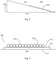
- Fig. 2 shows a schematic representation of a rotor blade of a wind turbine.
- the rotor blade 200 has a leading edge 210, a trailing edge 220, a rotor blade root 230, and a rotor blade tip 240.
- a trailing edge ridge 300 is provided in the region of the trailing edge 220.
Landscapes
- Engineering & Computer Science (AREA)
- Chemical & Material Sciences (AREA)
- Mechanical Engineering (AREA)
- Life Sciences & Earth Sciences (AREA)
- Fluid Mechanics (AREA)
- Physics & Mathematics (AREA)
- General Engineering & Computer Science (AREA)
- Combustion & Propulsion (AREA)
- Sustainable Energy (AREA)
- Sustainable Development (AREA)
- Health & Medical Sciences (AREA)
- Organic Chemistry (AREA)
- Polymers & Plastics (AREA)
- Medicinal Chemistry (AREA)
- Chemical Kinetics & Catalysis (AREA)
- Materials Engineering (AREA)
- Manufacturing & Machinery (AREA)
- Wind Motors (AREA)
Abstract
Description
- Die vorliegende Erfindung betrifft ein Verfahren zum Herstellen eines Windenergieanlagen-Rotorblattes und einen Windenergieanlagen-Rotorblatt-Hinterkantenkamm.
- Zur Reduzierung des durch die Rotorblätter einer Windenergieanlage erzeugten Lärms wird ein Hinterkantenkamm (trailing edge separation) an der Hinterkante eines Rotorblattes vorgesehen. Dieser Hinterkantenkamm weist typischerweise eine Mehrzahl von Zacken auf. Das Vorhandensein des Hinterkantenkamms bewirkt, dass der durch die Windenergieanlage und insbesondere durch das Rotorblatt erzeugte Lärm reduziert werden kann. Die Herstellung derartiger Rotorblätter ist jedoch aufwändig und kostenintensiv.
- Es ist daher eine Aufgabe der vorliegenden Erfindung, Verfahren zum Herstellen eines Windenergieanlagen-Rotorblattes mit einem verbesserten Hinterkantenkamm sowie ein Rotorblatt mit einem entsprechend verbesserten Hinterkantenkamm vorzusehen.
- Diese Aufgabe wird durch Verfahren zum Herstellen eines Windenergieanlagen-Rotorblattes nach Anspruch 1, einen Windenergieanlagen-Rotorblatt-Hinterkantenkamm gemäß Anspruch 3 gelöst.
- Somit wird ein Verfahren zum Herstellen eines Windenergieanlagen-Rotorblattes vorgesehen, welches eine Hinterkante aufweist. Ein Klebeband mit einer ersten und zweiten Klebefläche wird vorgesehen. Eine Mehrzahl von pultrudierten Stäben wird auf der zweiten Klebefläche des Klebebandes aufgeklebt, und der Hinterkantenkamm wird auf oder an einer Hinterkante des Rotorblattes mittels der ersten Klebefläche aufgeklebt.
- Gemäß einem Aspekt der Erfindung kann das Klebeband, nachdem die Mehrzahl der pultrudierten Stäbe auf der zweiten Klebeseite platziert sind, aufgerollt und das aufgerollte Klebeband beim Aufkleben auf die Hinterkante des Rotorblattes abgerollt werden.
- Ferner wird ein Windenergieanlagen-Rotorblatt-Hinterkantenkamm mit einem doppelseitigen Klebeband mit einer ersten und zweiten Klebeseite vorgesehen. Auf der ersten Klebeseite des doppelseitigen Klebebandes wird eine Mehrzahl von pultrudierten Stäben platziert. Die zweite Klebeseite dient dazu, den Hinterkantenkamm auf eine Hinterkante eines Rotorblattes zu kleben.
- Mit einem derartigen Hinterkantenkamm kann ein Rotorblatt auf einfache Art und Weise modifiziert werden, um den durch das Rotorblatt erzeugten Schall zu reduzieren. Insbesondere ist die Handhabung eines derartigen Hinterkantenkamms bestehend aus einem Klebeband vorteilhaft, weil das Klebeband flexibel ist und damit eine einfache Montage auf dem Rotorblatt erlaubt.
- Die pultrudierten Stäbe können vorab hergestellt und z.B. mittels einer Separiermaschine nebeneinander ausgerichtet und auf einer Klebeseite des doppelseitigen Klebebandes geklebt werden. Da lediglich eine der beiden Klebeseiten des Klebebandes mit der Mehrzahl von pultrudierten Stäben belegt ist und die andere Klebeseite mittels einer entsprechenden Abdeckung nicht klebt, kann das Klebeband mit den sich darauf befindlichen pultrudierten Stäben aufgewickelt werden. Dies führt zu einer erheblichen Verbesserung der Handhabbarkeit des Hinterkantenkamms.
- Somit kann ein flexibler Hinterkantenkamm erreicht werden, der auf einfache Art und Weise montiert werden kann.
- Dadurch, dass lediglich ein Klebeband verwendet wird, führt ein Aufbringen des Hinterkantenkamms an der Hinterkante des Rotorblattes nicht zu Steifigkeitssprüngen oder einer anderen strukturellen Beeinträchtigung.
- Mit dem Hinterkantenkamm kann ein als Borsten ausgestalteter Hinterkantenkamm auf einfache Art und Weise hergestellt und montiert werden.
- Die Erfindung betrifft ebenfalls ein Windenergieanlagen-Rotorblatt mit einem entsprechenden Hinterkantenkamm bestehend aus einem doppelseitigen Klebeband sowie einer Mehrzahl von pultrudierten Stäben auf einer Seite des Klebebandes. Der Hinterkantenkamm kann dann mittels der zweiten Klebeseite auf der Hinterkante des Rotorblattes platziert werden.
- Weitere Ausgestaltungen der Erfindung sind Gegenstand der Unteransprüche.
- Vorteile und Ausführungsbeispiele der Erfindung werden nachstehend unter Bezugnahme auf die Zeichnung näher erläutert.
- Fig. 1
- zeigt eine schematische Darstellung einer Windenergieanlage,
- Fig. 2
- zeigt eine schematische Darstellung eines Rotorblattes einer Windenergieanlage, und
- Fig. 3
- zeigt eine schematische Darstellung eines Hinterkantenkamms für ein Rotorblatt einer Windenergieanlage.
-
Fig. 1 zeigt eine schematische Darstellung einer Windenergieanlage gemäß der Erfindung. Die Windenergieanlage 100 weist einen Turm 102 und eine Gondel 104 auf dem Turm 102 auf. An der Gondel 104 ist ein aerodynamischer Rotor 106 mit drei Rotorblättern 200 und einem Spinner 110 vorgesehen. Der aerodynamische Rotor 106 wird im Betrieb der Windenergieanlage durch den Wind in eine Drehbewegung versetzt und dreht somit auch einen Rotor oder Läufer eines Generators, welcher direkt oder indirekt mit dem aerodynamischen Rotor 106 gekoppelt ist. Der elektrische Generator ist in der Gondel 104 angeordnet und erzeugt elektrische Energie. Die Pitchwinkel der Rotorblätter 200 können durch Pitchmotoren an den Rotorblattwurzeln der jeweiligen Rotorblätter 200 verändert werden. -
Fig. 2 zeigt eine schematische Darstellung eines Rotorblattes einer Windenergieanlage. Das Rotorblatt 200 weist eine Vorderkante 210, eine Hinterkante 220, eine Rotorblattwurzel 230 und eine Rotorblattspitze 240 auf. Im Bereich der Hinterkante 220 ist ein Hinterkantenkamm 300 vorgesehen. -
Fig. 3 zeigt eine schematische Darstellung eines Hinterkantenkamms für ein Rotorblatt einer Windenergieanlage. Der Hinterkantenkamm 300 weist ein (doppelseitiges) Klebeband 310 mit einer ersten und zweiten Klebeseite oder Klebefläche 311, 312 auf. Auf der zweiten Klebeseite 312 ist eine Mehrzahl von pultrudierten Stäben 320 platziert. Die erste Klebeseite 311 dient dazu, den Hinterkantenkamm 300 an einer Hinterkante 220 der Windenergieanlage zu befestigen bzw. zu kleben. - Die Länge der Stäbe kann gleich lang sein. Alternativ dazu können die Längen der Stäbe so variieren, dass es zu einer Zackenausbildung der Stäbe (analog zu den herkömmlichen Hinterkantenkämmen) kommt. Die Länge der Stäbe kann auch zur Rotorblattspitze hin abnehmen.
- Beispielsweis können die Stäbe einen Durchmesser von ca. zwischen 0,5 mm und 4 mm, vorzugsweise 1 mm aufweisen. Beispielsweise können die Stäbe 60 mm bis 100 mm, insbesondere ca. 80 mm über die Endkante hinausragen.
Claims (4)
- Verfahren zum Herstellen eines Windenergieanlagen-Rotorblattes (200), welches eine Hinterkante (220) aufweist, mit den Schritten:Vorsehen eines Klebebandes (310) mit einer ersten und zweiten Klebefläche (311, 312),Aufkleben einer Mehrzahl von pultrudierten Stäben (320) auf der zweiten Klebefläche (312) des Klebebandes (310), undAufkleben des Hinterkantenkamms (300) auf oder an einer Hinterkante (220) des Rotorblattes (200) mittels der ersten Klebefläche (311).
- Verfahren nach Anspruch 1, wobei
das Klebeband (310), nachdem die Mehrzahl der pultrudierten Stäbe (320) auf der zweiten Klebeseite (312) platziert sind, aufgerollt wird und das aufgerollte Klebeband (310) beim Aufkleben auf die Hinterkante (220) des Rotorblattes (200) abgerollt wird. - Windenergieanlagen-Rotorblatt-Hinterkantenkamm (300), miteinem Klebeband (310) mit einer ersten und zweiten Klebefläche (311, 312), undeiner Mehrzahl von pultrudierten Stäben (320) auf der zweiten Klebefläche (312),wobei die erste Klebefläche (311) dazu ausgestaltet ist, den Hinterkantenkamm (300) an einer Hinterkante eines Rotorblattes aufzukleben, so dass die pultrudierten Stäbe (320) über die Hinterkante (220) hinausragen.
- Windenergieanlagen-Rotorblatt (200), mit
einem Hinterkantenkamm (300) nach Anspruch 3, welcher mittels der ersten Klebefläche (311) des Klebebandes (310) auf einer Hinterkante (220) des Rotorblattes (200) aufgeklebt ist.
Priority Applications (1)
| Application Number | Priority Date | Filing Date | Title |
|---|---|---|---|
| EP23201792.1A EP4534276A1 (de) | 2023-10-05 | 2023-10-05 | Windenergieanlagen-rotorblatt-hinterkantenkamm und verfahren zum herstellen eines windenergieanlagen-rotorblattes |
Applications Claiming Priority (1)
| Application Number | Priority Date | Filing Date | Title |
|---|---|---|---|
| EP23201792.1A EP4534276A1 (de) | 2023-10-05 | 2023-10-05 | Windenergieanlagen-rotorblatt-hinterkantenkamm und verfahren zum herstellen eines windenergieanlagen-rotorblattes |
Publications (1)
| Publication Number | Publication Date |
|---|---|
| EP4534276A1 true EP4534276A1 (de) | 2025-04-09 |
Family
ID=88290768
Family Applications (1)
| Application Number | Title | Priority Date | Filing Date |
|---|---|---|---|
| EP23201792.1A Pending EP4534276A1 (de) | 2023-10-05 | 2023-10-05 | Windenergieanlagen-rotorblatt-hinterkantenkamm und verfahren zum herstellen eines windenergieanlagen-rotorblattes |
Country Status (1)
| Country | Link |
|---|---|
| EP (1) | EP4534276A1 (de) |
Citations (3)
| Publication number | Priority date | Publication date | Assignee | Title |
|---|---|---|---|---|
| US20070077150A1 (en) * | 2005-09-22 | 2007-04-05 | Gamesa Eolica, S.A. | Wind turbine with noise-reducing blade rotor |
| US20140072440A1 (en) * | 2012-09-11 | 2014-03-13 | General Electric Company | Attachment system for a wind turbine rotor blade accessory |
| US20170276117A1 (en) * | 2014-08-05 | 2017-09-28 | Ryan Church | Structure with rigid projections adapted to traverse a fluid environment |
-
2023
- 2023-10-05 EP EP23201792.1A patent/EP4534276A1/de active Pending
Patent Citations (3)
| Publication number | Priority date | Publication date | Assignee | Title |
|---|---|---|---|---|
| US20070077150A1 (en) * | 2005-09-22 | 2007-04-05 | Gamesa Eolica, S.A. | Wind turbine with noise-reducing blade rotor |
| US20140072440A1 (en) * | 2012-09-11 | 2014-03-13 | General Electric Company | Attachment system for a wind turbine rotor blade accessory |
| US20170276117A1 (en) * | 2014-08-05 | 2017-09-28 | Ryan Church | Structure with rigid projections adapted to traverse a fluid environment |
Similar Documents
| Publication | Publication Date | Title |
|---|---|---|
| DE102014206345A1 (de) | Verfahren zum Anbringen einer Zackenhinterkante an einer Blatthinterkante eines Rotorblattes | |
| DE102012109989A1 (de) | Windkraftturbinenrotorblatt mit Hinterkantenerweiterung und Befestigungsverfahren | |
| DE102012108124A1 (de) | Integriertes Blitzaufnehmersystem und Hinterkantengeräuschminderer für ein Windkraftanlagen-Rotorblatt | |
| DE102008042242A1 (de) | Verfahren zum Herstellen eines Ankerläufers eines Kommutatormotors, einen Kommutatormotor, und Antiblockierbremsvorrichtung | |
| WO2017085088A1 (de) | Windenergieanlagen-rotorblatt und windenergieanlage | |
| EP3634730B1 (de) | Verfahren zum herstellen eines windenergieanlagen-rotorblattes | |
| WO2018046519A1 (de) | Windenergieanlagen-rotorblatt | |
| DE19826086A1 (de) | Verfahren zum Herstellen eines Rotorblatts für Windkraftanlagen und Rotorblatt für Windkraftanlagen | |
| WO2014177363A2 (de) | Synchrongenerator-stator und synchrongenerator | |
| EP3740377A1 (de) | Verfahren zum herstellen von komponenten einer windenergieanlage, insbesondere eines windenergieanlagen-rotorblattes | |
| DE102015217331A1 (de) | Verfahren zum Nachrüsten einer Zackeneinheit an einer Hinterkante eines Windenergieanlagen-Rotorblattes und Zacken-Nachrüsteinheit für ein Windenergieanlagen-Rotorblatt | |
| EP4219934B1 (de) | Verfahren zur reduzierung einer geräuschemission eines windenergieanlagen-rotorblattes und windenergieanlagen-rotorblatt | |
| EP3564523B1 (de) | Flanschanschluss für ein windenergieanlagenrotorblatt, versteifungslage für einen flanschanschluss, flanscheinleger, windenergieanlagenrotorblatt, windenergieanlage sowie verfahren zum herstellen eines flanschanschlusses | |
| DE102018108906A1 (de) | Windenergieanlagen-Rotorblatt und Windenergieanlage | |
| EP4070890B1 (de) | Verfahren zum auftragen eines materials auf eine oberfläche eines windenergieanlagen-rotorblattes und material-applikator | |
| DE102013206121A1 (de) | Synchrongenerator-Polpaket | |
| WO2017042193A1 (de) | Verfahren zum nachrüsten einer zacken-nachrüsteinheit an einer hinterkante eines windenergieanlagen-rotorblattes und zacken-nachrüsteinheit für ein windenergieanlagen-rotorblatt | |
| EP3615792B1 (de) | Windenergieanlagen-rotorblatt und verfahren zum herstellen eines windenergieanlagen-rotorblattes | |
| EP4628288A1 (de) | Verfahren zum herstellen eines windenergieanlagen-rotorblattes | |
| EP3825550A1 (de) | Turmsegment und herstellungsverfahren | |
| EP4545281A1 (de) | Verfahren zum herstellen eines windenergieanlagen-rotorblattes | |
| DE102016101485A1 (de) | Verfahren zum Nachrüsten einer Zacken-Nachrüsteinheit an einer Hinterkante eines Windenergieanlagen-Rotorblattes und Zacken-Nachrüsteinheit für ein Windenergieanlagen-Rotorblatt | |
| EP3848574A1 (de) | Verfahren zum herstellen eines windenergieanlagen-rotorblattes | |
| DE29810364U1 (de) | Rotor für eine Windkraftanlage sowie Windkraftanlage | |
| DE102017126970A1 (de) | Rotorblatt und Rotor für eine Windenergieanlage, Windenergieanlage, Verfahren zur Herstellung eines Rotorblatts, zur Verbindung eines Rotorblatts mit einer Rotornabe und zur Reparatur eines Rotors einer Windenergieanlage |
Legal Events
| Date | Code | Title | Description |
|---|---|---|---|
| PUAI | Public reference made under article 153(3) epc to a published international application that has entered the european phase |
Free format text: ORIGINAL CODE: 0009012 |
|
| STAA | Information on the status of an ep patent application or granted ep patent |
Free format text: STATUS: THE APPLICATION HAS BEEN PUBLISHED |
|
| AK | Designated contracting states |
Kind code of ref document: A1 Designated state(s): AL AT BE BG CH CY CZ DE DK EE ES FI FR GB GR HR HU IE IS IT LI LT LU LV MC ME MK MT NL NO PL PT RO RS SE SI SK SM TR |
|
| STAA | Information on the status of an ep patent application or granted ep patent |
Free format text: STATUS: REQUEST FOR EXAMINATION WAS MADE |
|
| 17P | Request for examination filed |
Effective date: 20251009 |
|
| REG | Reference to a national code |
Ref country code: DE Ref legal event code: R079 Free format text: PREVIOUS MAIN CLASS: B29C0065500000 Ipc: F03D0001060000 |
|
| RIC1 | Information provided on ipc code assigned before grant |
Ipc: F03D 1/06 20060101AFI20260401BHEP Ipc: B29D 99/00 20100101ALI20260401BHEP Ipc: C08J 5/12 20060101ALI20260401BHEP Ipc: B29L 31/08 20060101ALN20260401BHEP Ipc: B29C 65/50 20060101ALN20260401BHEP |
|
| GRAP | Despatch of communication of intention to grant a patent |
Free format text: ORIGINAL CODE: EPIDOSNIGR1 |
|
| STAA | Information on the status of an ep patent application or granted ep patent |
Free format text: STATUS: GRANT OF PATENT IS INTENDED |