EP4534271A1 - Injection molding device - Google Patents
Injection molding device Download PDFInfo
- Publication number
- EP4534271A1 EP4534271A1 EP23815817.4A EP23815817A EP4534271A1 EP 4534271 A1 EP4534271 A1 EP 4534271A1 EP 23815817 A EP23815817 A EP 23815817A EP 4534271 A1 EP4534271 A1 EP 4534271A1
- Authority
- EP
- European Patent Office
- Prior art keywords
- plunger
- distributor
- fluid communication
- posture
- runner
- Prior art date
- Legal status (The legal status is an assumption and is not a legal conclusion. Google has not performed a legal analysis and makes no representation as to the accuracy of the status listed.)
- Pending
Links
Images





Classifications
-
- B—PERFORMING OPERATIONS; TRANSPORTING
- B29—WORKING OF PLASTICS; WORKING OF SUBSTANCES IN A PLASTIC STATE IN GENERAL
- B29C—SHAPING OR JOINING OF PLASTICS; SHAPING OF MATERIAL IN A PLASTIC STATE, NOT OTHERWISE PROVIDED FOR; AFTER-TREATMENT OF THE SHAPED PRODUCTS, e.g. REPAIRING
- B29C45/00—Injection moulding, i.e. forcing the required volume of moulding material through a nozzle into a closed mould; Apparatus therefor
- B29C45/16—Making multilayered or multicoloured articles
- B29C45/1684—Injecting parison-like articles
-
- B—PERFORMING OPERATIONS; TRANSPORTING
- B29—WORKING OF PLASTICS; WORKING OF SUBSTANCES IN A PLASTIC STATE IN GENERAL
- B29C—SHAPING OR JOINING OF PLASTICS; SHAPING OF MATERIAL IN A PLASTIC STATE, NOT OTHERWISE PROVIDED FOR; AFTER-TREATMENT OF THE SHAPED PRODUCTS, e.g. REPAIRING
- B29C45/00—Injection moulding, i.e. forcing the required volume of moulding material through a nozzle into a closed mould; Apparatus therefor
- B29C45/17—Component parts, details or accessories; Auxiliary operations
- B29C45/76—Measuring, controlling or regulating
- B29C45/77—Measuring, controlling or regulating of velocity or pressure of moulding material
-
- B—PERFORMING OPERATIONS; TRANSPORTING
- B29—WORKING OF PLASTICS; WORKING OF SUBSTANCES IN A PLASTIC STATE IN GENERAL
- B29B—PREPARATION OR PRETREATMENT OF THE MATERIAL TO BE SHAPED; MAKING GRANULES OR PREFORMS; RECOVERY OF PLASTICS OR OTHER CONSTITUENTS OF WASTE MATERIAL CONTAINING PLASTICS
- B29B11/00—Making preforms
- B29B11/06—Making preforms by moulding the material
- B29B11/08—Injection moulding
-
- B—PERFORMING OPERATIONS; TRANSPORTING
- B29—WORKING OF PLASTICS; WORKING OF SUBSTANCES IN A PLASTIC STATE IN GENERAL
- B29B—PREPARATION OR PRETREATMENT OF THE MATERIAL TO BE SHAPED; MAKING GRANULES OR PREFORMS; RECOVERY OF PLASTICS OR OTHER CONSTITUENTS OF WASTE MATERIAL CONTAINING PLASTICS
- B29B11/00—Making preforms
- B29B11/14—Making preforms characterised by structure or composition
-
- B—PERFORMING OPERATIONS; TRANSPORTING
- B29—WORKING OF PLASTICS; WORKING OF SUBSTANCES IN A PLASTIC STATE IN GENERAL
- B29C—SHAPING OR JOINING OF PLASTICS; SHAPING OF MATERIAL IN A PLASTIC STATE, NOT OTHERWISE PROVIDED FOR; AFTER-TREATMENT OF THE SHAPED PRODUCTS, e.g. REPAIRING
- B29C45/00—Injection moulding, i.e. forcing the required volume of moulding material through a nozzle into a closed mould; Apparatus therefor
- B29C45/0001—Injection moulding, i.e. forcing the required volume of moulding material through a nozzle into a closed mould; Apparatus therefor characterised by the choice of material
-
- B—PERFORMING OPERATIONS; TRANSPORTING
- B29—WORKING OF PLASTICS; WORKING OF SUBSTANCES IN A PLASTIC STATE IN GENERAL
- B29C—SHAPING OR JOINING OF PLASTICS; SHAPING OF MATERIAL IN A PLASTIC STATE, NOT OTHERWISE PROVIDED FOR; AFTER-TREATMENT OF THE SHAPED PRODUCTS, e.g. REPAIRING
- B29C45/00—Injection moulding, i.e. forcing the required volume of moulding material through a nozzle into a closed mould; Apparatus therefor
- B29C45/03—Injection moulding apparatus
- B29C45/12—Injection moulding apparatus using two or more fixed moulds, e.g. in tandem
- B29C45/125—Injection moulding apparatus using two or more fixed moulds, e.g. in tandem using a material distributing system
-
- B—PERFORMING OPERATIONS; TRANSPORTING
- B29—WORKING OF PLASTICS; WORKING OF SUBSTANCES IN A PLASTIC STATE IN GENERAL
- B29C—SHAPING OR JOINING OF PLASTICS; SHAPING OF MATERIAL IN A PLASTIC STATE, NOT OTHERWISE PROVIDED FOR; AFTER-TREATMENT OF THE SHAPED PRODUCTS, e.g. REPAIRING
- B29C45/00—Injection moulding, i.e. forcing the required volume of moulding material through a nozzle into a closed mould; Apparatus therefor
- B29C45/03—Injection moulding apparatus
- B29C45/13—Injection moulding apparatus using two or more injection units co-operating with a single mould
-
- B—PERFORMING OPERATIONS; TRANSPORTING
- B29—WORKING OF PLASTICS; WORKING OF SUBSTANCES IN A PLASTIC STATE IN GENERAL
- B29C—SHAPING OR JOINING OF PLASTICS; SHAPING OF MATERIAL IN A PLASTIC STATE, NOT OTHERWISE PROVIDED FOR; AFTER-TREATMENT OF THE SHAPED PRODUCTS, e.g. REPAIRING
- B29C45/00—Injection moulding, i.e. forcing the required volume of moulding material through a nozzle into a closed mould; Apparatus therefor
- B29C45/16—Making multilayered or multicoloured articles
-
- B—PERFORMING OPERATIONS; TRANSPORTING
- B29—WORKING OF PLASTICS; WORKING OF SUBSTANCES IN A PLASTIC STATE IN GENERAL
- B29C—SHAPING OR JOINING OF PLASTICS; SHAPING OF MATERIAL IN A PLASTIC STATE, NOT OTHERWISE PROVIDED FOR; AFTER-TREATMENT OF THE SHAPED PRODUCTS, e.g. REPAIRING
- B29C45/00—Injection moulding, i.e. forcing the required volume of moulding material through a nozzle into a closed mould; Apparatus therefor
- B29C45/17—Component parts, details or accessories; Auxiliary operations
- B29C45/18—Feeding the material into the injection moulding apparatus, i.e. feeding the non-plastified material into the injection unit
- B29C45/1866—Feeding multiple materials
-
- B—PERFORMING OPERATIONS; TRANSPORTING
- B29—WORKING OF PLASTICS; WORKING OF SUBSTANCES IN A PLASTIC STATE IN GENERAL
- B29C—SHAPING OR JOINING OF PLASTICS; SHAPING OF MATERIAL IN A PLASTIC STATE, NOT OTHERWISE PROVIDED FOR; AFTER-TREATMENT OF THE SHAPED PRODUCTS, e.g. REPAIRING
- B29C45/00—Injection moulding, i.e. forcing the required volume of moulding material through a nozzle into a closed mould; Apparatus therefor
- B29C45/17—Component parts, details or accessories; Auxiliary operations
- B29C45/20—Injection nozzles
-
- B—PERFORMING OPERATIONS; TRANSPORTING
- B29—WORKING OF PLASTICS; WORKING OF SUBSTANCES IN A PLASTIC STATE IN GENERAL
- B29C—SHAPING OR JOINING OF PLASTICS; SHAPING OF MATERIAL IN A PLASTIC STATE, NOT OTHERWISE PROVIDED FOR; AFTER-TREATMENT OF THE SHAPED PRODUCTS, e.g. REPAIRING
- B29C45/00—Injection moulding, i.e. forcing the required volume of moulding material through a nozzle into a closed mould; Apparatus therefor
- B29C45/17—Component parts, details or accessories; Auxiliary operations
- B29C45/26—Moulds
- B29C45/27—Sprue channels ; Runner channels or runner nozzles
-
- B—PERFORMING OPERATIONS; TRANSPORTING
- B29—WORKING OF PLASTICS; WORKING OF SUBSTANCES IN A PLASTIC STATE IN GENERAL
- B29C—SHAPING OR JOINING OF PLASTICS; SHAPING OF MATERIAL IN A PLASTIC STATE, NOT OTHERWISE PROVIDED FOR; AFTER-TREATMENT OF THE SHAPED PRODUCTS, e.g. REPAIRING
- B29C45/00—Injection moulding, i.e. forcing the required volume of moulding material through a nozzle into a closed mould; Apparatus therefor
- B29C45/17—Component parts, details or accessories; Auxiliary operations
- B29C45/26—Moulds
- B29C45/27—Sprue channels ; Runner channels or runner nozzles
- B29C45/2701—Details not specific to hot or cold runner channels
- B29C45/2703—Means for controlling the runner flow, e.g. runner switches, adjustable runners or gates
-
- B—PERFORMING OPERATIONS; TRANSPORTING
- B29—WORKING OF PLASTICS; WORKING OF SUBSTANCES IN A PLASTIC STATE IN GENERAL
- B29C—SHAPING OR JOINING OF PLASTICS; SHAPING OF MATERIAL IN A PLASTIC STATE, NOT OTHERWISE PROVIDED FOR; AFTER-TREATMENT OF THE SHAPED PRODUCTS, e.g. REPAIRING
- B29C45/00—Injection moulding, i.e. forcing the required volume of moulding material through a nozzle into a closed mould; Apparatus therefor
- B29C45/17—Component parts, details or accessories; Auxiliary operations
- B29C45/46—Means for plasticising or homogenising the moulding material or forcing it into the mould
- B29C45/53—Means for plasticising or homogenising the moulding material or forcing it into the mould using injection ram or piston
- B29C45/54—Means for plasticising or homogenising the moulding material or forcing it into the mould using injection ram or piston and plasticising screw
-
- B—PERFORMING OPERATIONS; TRANSPORTING
- B29—WORKING OF PLASTICS; WORKING OF SUBSTANCES IN A PLASTIC STATE IN GENERAL
- B29C—SHAPING OR JOINING OF PLASTICS; SHAPING OF MATERIAL IN A PLASTIC STATE, NOT OTHERWISE PROVIDED FOR; AFTER-TREATMENT OF THE SHAPED PRODUCTS, e.g. REPAIRING
- B29C45/00—Injection moulding, i.e. forcing the required volume of moulding material through a nozzle into a closed mould; Apparatus therefor
- B29C45/17—Component parts, details or accessories; Auxiliary operations
- B29C45/46—Means for plasticising or homogenising the moulding material or forcing it into the mould
- B29C45/58—Details
- B29C45/586—Injection or transfer plungers
-
- B—PERFORMING OPERATIONS; TRANSPORTING
- B29—WORKING OF PLASTICS; WORKING OF SUBSTANCES IN A PLASTIC STATE IN GENERAL
- B29C—SHAPING OR JOINING OF PLASTICS; SHAPING OF MATERIAL IN A PLASTIC STATE, NOT OTHERWISE PROVIDED FOR; AFTER-TREATMENT OF THE SHAPED PRODUCTS, e.g. REPAIRING
- B29C45/00—Injection moulding, i.e. forcing the required volume of moulding material through a nozzle into a closed mould; Apparatus therefor
- B29C45/17—Component parts, details or accessories; Auxiliary operations
- B29C45/76—Measuring, controlling or regulating
-
- B—PERFORMING OPERATIONS; TRANSPORTING
- B29—WORKING OF PLASTICS; WORKING OF SUBSTANCES IN A PLASTIC STATE IN GENERAL
- B29C—SHAPING OR JOINING OF PLASTICS; SHAPING OF MATERIAL IN A PLASTIC STATE, NOT OTHERWISE PROVIDED FOR; AFTER-TREATMENT OF THE SHAPED PRODUCTS, e.g. REPAIRING
- B29C45/00—Injection moulding, i.e. forcing the required volume of moulding material through a nozzle into a closed mould; Apparatus therefor
- B29C45/17—Component parts, details or accessories; Auxiliary operations
- B29C45/26—Moulds
- B29C45/27—Sprue channels ; Runner channels or runner nozzles
- B29C45/30—Flow control means disposed within the sprue channel, e.g. "torpedo" construction
- B29C2045/308—Mixing or stirring devices
-
- B—PERFORMING OPERATIONS; TRANSPORTING
- B29—WORKING OF PLASTICS; WORKING OF SUBSTANCES IN A PLASTIC STATE IN GENERAL
- B29C—SHAPING OR JOINING OF PLASTICS; SHAPING OF MATERIAL IN A PLASTIC STATE, NOT OTHERWISE PROVIDED FOR; AFTER-TREATMENT OF THE SHAPED PRODUCTS, e.g. REPAIRING
- B29C45/00—Injection moulding, i.e. forcing the required volume of moulding material through a nozzle into a closed mould; Apparatus therefor
- B29C45/17—Component parts, details or accessories; Auxiliary operations
- B29C45/46—Means for plasticising or homogenising the moulding material or forcing it into the mould
- B29C45/53—Means for plasticising or homogenising the moulding material or forcing it into the mould using injection ram or piston
- B29C45/54—Means for plasticising or homogenising the moulding material or forcing it into the mould using injection ram or piston and plasticising screw
- B29C2045/545—Means for plasticising or homogenising the moulding material or forcing it into the mould using injection ram or piston and plasticising screw alternately operating injection plungers
-
- B—PERFORMING OPERATIONS; TRANSPORTING
- B29—WORKING OF PLASTICS; WORKING OF SUBSTANCES IN A PLASTIC STATE IN GENERAL
- B29C—SHAPING OR JOINING OF PLASTICS; SHAPING OF MATERIAL IN A PLASTIC STATE, NOT OTHERWISE PROVIDED FOR; AFTER-TREATMENT OF THE SHAPED PRODUCTS, e.g. REPAIRING
- B29C2945/00—Indexing scheme relating to injection moulding, i.e. forcing the required volume of moulding material through a nozzle into a closed mould
- B29C2945/76—Measuring, controlling or regulating
- B29C2945/76003—Measured parameter
- B29C2945/76056—Flow rate
-
- B—PERFORMING OPERATIONS; TRANSPORTING
- B29—WORKING OF PLASTICS; WORKING OF SUBSTANCES IN A PLASTIC STATE IN GENERAL
- B29C—SHAPING OR JOINING OF PLASTICS; SHAPING OF MATERIAL IN A PLASTIC STATE, NOT OTHERWISE PROVIDED FOR; AFTER-TREATMENT OF THE SHAPED PRODUCTS, e.g. REPAIRING
- B29C2945/00—Indexing scheme relating to injection moulding, i.e. forcing the required volume of moulding material through a nozzle into a closed mould
- B29C2945/76—Measuring, controlling or regulating
- B29C2945/76003—Measured parameter
- B29C2945/76083—Position
-
- B—PERFORMING OPERATIONS; TRANSPORTING
- B29—WORKING OF PLASTICS; WORKING OF SUBSTANCES IN A PLASTIC STATE IN GENERAL
- B29C—SHAPING OR JOINING OF PLASTICS; SHAPING OF MATERIAL IN A PLASTIC STATE, NOT OTHERWISE PROVIDED FOR; AFTER-TREATMENT OF THE SHAPED PRODUCTS, e.g. REPAIRING
- B29C2945/00—Indexing scheme relating to injection moulding, i.e. forcing the required volume of moulding material through a nozzle into a closed mould
- B29C2945/76—Measuring, controlling or regulating
- B29C2945/76177—Location of measurement
- B29C2945/7618—Injection unit
- B29C2945/762—Injection unit injection piston
-
- B—PERFORMING OPERATIONS; TRANSPORTING
- B29—WORKING OF PLASTICS; WORKING OF SUBSTANCES IN A PLASTIC STATE IN GENERAL
- B29C—SHAPING OR JOINING OF PLASTICS; SHAPING OF MATERIAL IN A PLASTIC STATE, NOT OTHERWISE PROVIDED FOR; AFTER-TREATMENT OF THE SHAPED PRODUCTS, e.g. REPAIRING
- B29C2945/00—Indexing scheme relating to injection moulding, i.e. forcing the required volume of moulding material through a nozzle into a closed mould
- B29C2945/76—Measuring, controlling or regulating
- B29C2945/76177—Location of measurement
- B29C2945/76254—Mould
- B29C2945/76274—Mould runners, nozzles
-
- B—PERFORMING OPERATIONS; TRANSPORTING
- B29—WORKING OF PLASTICS; WORKING OF SUBSTANCES IN A PLASTIC STATE IN GENERAL
- B29C—SHAPING OR JOINING OF PLASTICS; SHAPING OF MATERIAL IN A PLASTIC STATE, NOT OTHERWISE PROVIDED FOR; AFTER-TREATMENT OF THE SHAPED PRODUCTS, e.g. REPAIRING
- B29C2945/00—Indexing scheme relating to injection moulding, i.e. forcing the required volume of moulding material through a nozzle into a closed mould
- B29C2945/76—Measuring, controlling or regulating
- B29C2945/76177—Location of measurement
- B29C2945/76287—Moulding material
-
- B—PERFORMING OPERATIONS; TRANSPORTING
- B29—WORKING OF PLASTICS; WORKING OF SUBSTANCES IN A PLASTIC STATE IN GENERAL
- B29C—SHAPING OR JOINING OF PLASTICS; SHAPING OF MATERIAL IN A PLASTIC STATE, NOT OTHERWISE PROVIDED FOR; AFTER-TREATMENT OF THE SHAPED PRODUCTS, e.g. REPAIRING
- B29C2945/00—Indexing scheme relating to injection moulding, i.e. forcing the required volume of moulding material through a nozzle into a closed mould
- B29C2945/76—Measuring, controlling or regulating
- B29C2945/76344—Phase or stage of measurement
- B29C2945/76351—Feeding
- B29C2945/76354—Feeding raw materials
-
- B—PERFORMING OPERATIONS; TRANSPORTING
- B29—WORKING OF PLASTICS; WORKING OF SUBSTANCES IN A PLASTIC STATE IN GENERAL
- B29C—SHAPING OR JOINING OF PLASTICS; SHAPING OF MATERIAL IN A PLASTIC STATE, NOT OTHERWISE PROVIDED FOR; AFTER-TREATMENT OF THE SHAPED PRODUCTS, e.g. REPAIRING
- B29C2945/00—Indexing scheme relating to injection moulding, i.e. forcing the required volume of moulding material through a nozzle into a closed mould
- B29C2945/76—Measuring, controlling or regulating
- B29C2945/76494—Controlled parameter
- B29C2945/76568—Position
-
- B—PERFORMING OPERATIONS; TRANSPORTING
- B29—WORKING OF PLASTICS; WORKING OF SUBSTANCES IN A PLASTIC STATE IN GENERAL
- B29C—SHAPING OR JOINING OF PLASTICS; SHAPING OF MATERIAL IN A PLASTIC STATE, NOT OTHERWISE PROVIDED FOR; AFTER-TREATMENT OF THE SHAPED PRODUCTS, e.g. REPAIRING
- B29C2945/00—Indexing scheme relating to injection moulding, i.e. forcing the required volume of moulding material through a nozzle into a closed mould
- B29C2945/76—Measuring, controlling or regulating
- B29C2945/76655—Location of control
- B29C2945/76732—Mould
- B29C2945/76752—Mould runners, nozzles
- B29C2945/76755—Mould runners, nozzles nozzles
-
- B—PERFORMING OPERATIONS; TRANSPORTING
- B29—WORKING OF PLASTICS; WORKING OF SUBSTANCES IN A PLASTIC STATE IN GENERAL
- B29K—INDEXING SCHEME ASSOCIATED WITH SUBCLASSES B29B, B29C OR B29D, RELATING TO MOULDING MATERIALS OR TO MATERIALS FOR MOULDS, REINFORCEMENTS, FILLERS OR PREFORMED PARTS, e.g. INSERTS
- B29K2105/00—Condition, form or state of moulded material or of the material to be shaped
- B29K2105/26—Scrap or recycled material
-
- Y—GENERAL TAGGING OF NEW TECHNOLOGICAL DEVELOPMENTS; GENERAL TAGGING OF CROSS-SECTIONAL TECHNOLOGIES SPANNING OVER SEVERAL SECTIONS OF THE IPC; TECHNICAL SUBJECTS COVERED BY FORMER USPC CROSS-REFERENCE ART COLLECTIONS [XRACs] AND DIGESTS
- Y02—TECHNOLOGIES OR APPLICATIONS FOR MITIGATION OR ADAPTATION AGAINST CLIMATE CHANGE
- Y02W—CLIMATE CHANGE MITIGATION TECHNOLOGIES RELATED TO WASTEWATER TREATMENT OR WASTE MANAGEMENT
- Y02W30/00—Technologies for solid waste management
- Y02W30/50—Reuse, recycling or recovery technologies
- Y02W30/62—Plastics recycling; Rubber recycling
Definitions
- the present application relates to an injection molding device.
- Patent Document 1 discloses a preform manufacturing device that includes a decontamination machine that removes contaminants in thermoplastic resin flakes generated from a used plastic container, and an injection molding machine that performs injection molding of a thermoplastic resin supplied from the decontamination machine and manufactures a preform from the thermoplastic resin flakes.
- recycled materials are derived from used materials which are different from each other in various conditions (application, shape, processing conditions, etc.) relating to their origins, variations in quality may be recognized as compared with virgin materials manufactured under uniform manufacturing conditions. Therefore, in order to manufacture a plastic container using a recycled material, it is necessary to take measures such as absorbing variations in quality on the raw material side by adjusting manufacturing conditions.
- Patent Document 1 discloses a device for manufacturing a preform using a virgin material alone, a recycled material alone, or a mixture of a virgin material and a recycled material as a material.
- Patent Document 1 JP 2019-514728 T (or US 2019/126512 A )
- a first injection molding device includes a first injection section including a first plasticizing device, a first plunger, and a first distributor connected to the first plasticizing device and the first plunger, a second injection section including a second plasticizing device, a second plunger, and a second distributor connected to the second plasticizing device and the second plunger; a mold mounting unit, and a hot runner in fluid communication with the first injection section and the second injection section, wherein a posture in which the first plasticizing device and the first plunger are in fluid communication and a posture in which the first plunger and the hot runner are in fluid communication are selectable as a posture of the first distributor, a posture in which the second plasticizing device and the second plunger are in fluid communication and a posture in which the second plunger and the hot runner are in fluid communication are selectable as a posture of the second distributor, the hot runner includes a first sprue runner, a second sprue runner, and a nozzle; and the nozzle is provided in fluid communication with the
- a second injection molding device includes an injection section including a first plasticizing device, a second plasticizing device, a plunger, and a distributor, a mold mounting unit, and a hot runner in fluid communication with the injection section, wherein a posture in which the first plasticizing device and the plunger are in fluid communication, a posture in which the second plasticizing device and the plunger are in fluid communication, and a posture in which the plunger and the hot runner are in fluid communication are selectable as a posture of the distributor, the hot runner includes a first sprue runner, a second sprue runner, and a nozzle, and the nozzle is provided in fluid communication with the first sprue runner and the second sprue runner, and in fluid communication with a mold mounted on the mold mounting unit.
- supply conditions such as a supply order and a supply ratio can be adjusted when supplying the first material supplied through the first plasticizing device and the second material supplied through the second plasticizing device to the mold.
- the quality of the obtained molded body is easily stabilized.
- the first distributor and the second distributor are connected to each other, and a posture in which the first plunger is in fluid communication with at least one of the second plasticizing device and the second plunger is selectable as the postures of the first distributor and the second distributor.
- the first material supplied through the first plasticizing device and the second material supplied through the second plasticizing device can be mixed in the first plunger, the physical properties of the material can be easily adjusted.
- the injection molding device according to the present invention further preferably includes a control device configured to control operations of the first plunger and the second plunger.
- the injection molding device further preferably includes a first flow meter provided in a flow path between the first distributor and the hot runner; and a second flow meter provided in a flow path between the second distributor and the hot runner; wherein the control device is configured to control operations of the first plunger and the second plunger in accordance with an instruction value of the first flow meter and an instruction value of the second flow meter.
- the injection molding device further includes a first displacement gauge configured to detect a displacement of the plunger of the first piston and a second displacement gauge configured to detect a displacement of the plunger of the second piston, and the control device is preferably capable of controlling operations of the first plunger and the second plunger in accordance with an instruction value of the first displacement gauge and an instruction value of the second displacement gauge.
- the hot runner preferably includes a stem configured to open and close the nozzle, and an adjustment device configured to adjust a position of the stem.
- the adjustment device preferably includes a servomotor and is configured to adjust the position of the stem in accordance with a rotational speed of the servomotor.
- the adjustment device includes a magnetic displacement gauge and a hydraulic device configured to move the stem, and the hydraulic device is controlled in accordance with an instruction value of the magnetic displacement gauge.
- the injection molding device further includes a third distributor provided between the hot runner and each of the first injection section and the second injection section, wherein as a posture of the third distributor, a posture in which the first injection section and the first sprue runner are in fluid communication and the second injection section and the second sprue runner are in fluid communication, and a posture in which the first injection section and the second sprue runner are in fluid communication, and the second injection section and the first sprue runner are in fluid communication are selectable.
- the material to be supplied to the first sprue runner and second sprue runner can be arbitrarily selected.
- the injection molding device according to the present invention further preferably includes a stationary mixer provided in a flow path between the first plunger and the hot runner.
- the material supplied from the first plunger to the hot runner can be easily made to a uniform state.
- the injection molding device according to the present invention further preferably includes a third plasticizing device, and a posture in which the third plasticizing device and the first plunger are in fluid communication is further selectable as the posture of the first distributor.
- the physical properties of the material can be easily adjusted.
- the injection molding device according to the present invention is preferably provided with a raw material supply unit configured to supply a resin in a molten state to the first plasticizing device.
- the material subjected to pre-treatment in the molten state can be supplied to the first plasticizing device.
- the raw material supply unit includes an extruder configured to melt and extrude a recycled material and a decontamination machine configured to remove a foreign matter contained in the recycled material.
- the decontamination treated recycled material can be used as the first material to be supplied through the first plasticizing device.
- the step of pelletizing the recycled material can be omitted.
- FIG. 1 illustrates a preform 100 for a plastic container.
- the plastic container is a plastic bottle which is mainly used to accommodate beverages, foods, and the like, and is made of polyethylene terephthalate (PET).
- PET polyethylene terephthalate
- the plastic container is not limited thereto, and may be made of plastic such as polypropylene (PP) or polyethylene (PE).
- PP polypropylene
- PE polyethylene
- the plastic container may also be polyethylene naphthalate (PEN), in particular a plant bottle made from a plant or the like.
- PEN polyethylene naphthalate
- the preform 100 has a shape like a test tube including a mouth portion 100a fitted with a cap of a plastic container, a cylindrical body portion 100b formed in continuation with the mouth portion 100a, and a bottom portion 100c that closes one end portion of the cylindrical body portion.
- One end portion of the mouth portion 100a is opened, and the outer peripheral surface thereof is formed with a male screw to be screwed with a female screw formed on the cap of the plastic container.
- the plastic container is molded by expanding a test tube-shaped preform 100 by stretch blow molding.
- FIGS. 2 and 3 show schematic views of a manufacturing system 10.
- the manufacturing system 10 includes a pre-treatment unit 12 for pre-treatment a recycled material RC as a first molten material, and a molding machine 14 as shown in FIG. 3 .
- the preform 100 is generally manufactured using the molding machine 14 by using a virgin material VM serving as a second molten material containing petroleum or the like as a raw material, a recycled material RC containing used plastic container as a raw material, or a composite material such as a mixture of the virgin material VM and the recycled material RC as a raw material.
- the recycled material RC is charged into the molding machine 14 after the impurities are removed in advance by the pre-treatment unit 12.
- the composite material is described as the virgin material VM and the recycled material RC, but no such limitation is intended, and for example, a plastic container may be manufactured by a composite material of a petroleum-derived plastic material and a bioplastic material.
- a recycled material such as bioplastic or chemical recycled plastic, from which a material having a relatively stable quality can be easily obtained
- a recycled material such as bioplastic or chemical recycled plastic, from which a material having a relatively stable quality can be easily obtained. Since the virgin material VM or an alternative material is supplied to a second plasticizing device 38 via a hopper 36 as will be described later, it is preferable that a material is in a form suitable for supply from the hopper 36 such as a pellet form or a powder form.
- a material is in a form suitable for supply from the hopper 36 such as a pellet form or a powder form.
- the chemical recycled plastics and the like exemplified above commercially available products in pellet form or powder form are available, and the material can be pelletized or powdered through a known method.
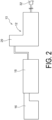
- the pre-treatment unit 12 serving as an example of a raw material supply unit includes a dryer 16, an extruder 18, and a decontamination machine 20.
- the recycled material RC is a thermoplastic resin flake serving as an example of a flake-like recycled material, for example, a PET flake obtained by washing and then pulverizing a used PET bottle (a washing machine and a pulverizer are not shown).
- the PET flakes are assumed to be small pieces of about 8 mm square.
- the recycled material RC is charged into a tank of the dryer 16, dried in the dryer 16, and then supplied to the extruder 18.
- the recycled material RC dried in the dryer 16 is sent to the extruder 18 and heated while being stirred. Therefore, the recycled material RC is melted and plasticized.
- the virgin material VM may be supplied to the extruder 18. In this case, the supply position of the virgin agent VM may be the dryer 16 or the extruder 18.
- the recycled material RC plasticized in the extruder 18 is sent to the decontamination machine 20.
- the decontamination machine 20 interiorly includes a decontamination container connected to a vacuum pump, and can volatilize contaminants in the recycled material RC, that is, in the thermoplastic resin by heating the recycled material RC charged into the decontamination container under vacuum. Thus, contaminants in the recycled material RC can be removed. Note that both the vacuum pump and the decontamination container are not illustrated.
- the decontaminated recycled material RC is supplied to a molding machine 14.
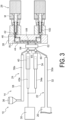
- the molding machine 14 includes a first injection section 22, a second injection section 24, a hot runner 26, a mold mounting unit 28, and a control device 30.
- a mold M is mounted on the mold mounting unit 28.
- the mold M is provided with a plurality of cavities in correspondence with the shape of a preform 100, and a plurality of preforms 100 can be manufactured by one injection molding.
- the first injection section 22 includes a first plasticizing device 32, a first plunger 34, and a first distributor 60.
- the first plasticizing device 32 has a screw (not shown) extending in the longitudinal direction inside a housing 32a thereof, and is heated by a heater.
- the thermoplastic resin of the recycled material RC supplied from the decontamination machine 20 is supplied in a molten state to the inside of the first plasticizing device 32, and is stirred in a heated state, so that a plasticized state can be maintained.
- a distal end portion of the first plasticizing device 32 is coupled with the first plunger 34 by way of the first distributor 60.
- the first plunger 34 has, on the inner side, a first piston 34a configured to be slidable along the longitudinal direction of the first plunger 34.
- the recycled material RC in the first plasticizing device 32 is sucked up into the first plunger 34 by sliding the first piston 34a in the direction of pulling out from the first plunger 34.
- the recycled material RC sucked up into the first plunger 34 can be pressurized, that is, extruded toward the hot runner 26 by sliding the first piston 34a in a direction of pushing into the first plunger 34.
- the first plunger 34 is connected to the control device 30, and is configured to control the amount of recycled material RC to be extruded from the first plunger 34 by controlling the sliding, that is, the movement amount of the first plunger 34.
- the first distributor 60 is coupled to the hot runner 26 by way of a third distributor 62 to be described later.
- the recycled material RC extruded by the first plunger 34 is configured to flow into the hot runner 26 through the third distributor 62.
- the molding machine 14 includes the second injection section 24 for supplying the virgin material VM to the mold M installed in the mold mounting unit 28, and the second injection section 24 includes a hopper 36 into which the pellet-like virgin material VM is charged, a second plasticizing device 38, a second plunger 40, and a second distributor 64.
- the second plasticizing device 38 has a screw (not shown) extending in the longitudinal direction inside a housing 38a thereof, and is heated by a heater.
- the thermoplastic resin of the virgin material VM supplied in a pellet state from the hopper 36 is plasticized by being stirred in a heated state in the second plasticizing device 38.
- a distal end portion of the second plasticizing device 38 is coupled with the second plunger 40 by way of the second distributor 64.
- the second plunger 40 has, on the inner side, a second piston 40a configured to be slidable along the longitudinal direction of the second plunger 40.
- the virgin material VM in the second plasticizing device 38 is sucked up into the second plunger 40 by sliding the second piston 40a in the direction of pulling out from the second plunger 40.
- the virgin material VM sucked up into the second plunger 40 can be pressurized, that is, extruded toward the hot runner 26 by sliding the second piston 40a in a direction of pushing into the second plunger 40.
- the second plunger 40 is connected to the control device 30, and is configured to control the amount of virgin material VM to be extruded from the second plunger 40 by controlling the sliding, that is, the movement amount of the second plunger 40.
- the second distributor 64 is coupled to the hot runner 26 by way of a third distributor 62 to be described later.
- the virgin material VM extruded by the second plunger 40 is configured to flow into the hot runner 26 through the third distributor 62.
- the first distributor 60 and the second distributor 64 are coupled to each other via piping 65, which allows the first plunger 34 and the second plunger 40 to be in fluid communication.
- the virgin material VM in the second plunger 40 can flow to the first plunger 34 via the second distributor 64, the piping 65, and the first distributor 60, and the recycled material RC supplied from the first plasticizing device 32 and the virgin material VM supplied from the second plasticizing device 38 via the second plunger 40 can be mixed.
- the recycled material RC can also be supplied to the second plunger 40.
- the first distributor 60 has a shape in which a first flow path 60b, a second flow path 60c, and a third flow path 60d for circulating the recycled material RC and the virgin material VM are formed to be spaced apart from each other in the axial direction inside a cylindrical main body 60a.
- the posture of any one of the first flow path 60b, the second flow path 60c, and the third flow path 60d can be changed to align with two or three of the first plasticizing device 32, the first plunger 34, the second distributor 64, and the third distributor 62 thereby achieving fluid communication according to the purpose. Since the shape and function of the second distributor 64 are similar to those of the first distributor 60, the description thereof will be omitted.
- the first flow path 60b has openings on three sides separated by 90° in the cross section of the main body 60a, and these openings are directed to the first plasticizing device 32, the first plunger 34, and the second distributor 64, respectively, so that the three can be in fluid communication.
- the posture in which the first distributor 60 and the second plunger 40 are in fluid communication is selected as the posture of the second distributor 64, the first plasticizing device 32, the first plunger 34, and the second plunger 40 are in fluid communication.
- the recycled material RC supplied from the first plasticizing device 32 and the virgin material VM supplied from the second plasticizing device 38 via the second plunger 40 can be guided to the first plunger 34.
- the second flow path 60c has openings on two sides separated by 180° in the cross section of the main body 60a, and these openings are directed to the first plunger 34 and the hot runner 26, respectively, so that the two can be in fluid communication.
- the third distributor 62 is provided between the first distributor 60 and the hot runner 26, the first distributor 60 and the third distributor 62 are in fluid communication. In this state, the material can be injected from the first plunger 34 to the hot runner 26.
- the third flow path 60d has openings on two sides separated by 90° in the cross section of the main body 60a, and these openings are directed to the first plasticizing device 32 and the first plunger 34, respectively, so that the two can be in fluid communication.
- the recycled material RC supplied from the first plasticizing device 32 can be guided to the first plunger 34.
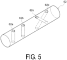
- FIG. 5 is a perspective view of a third distributor 62.
- the third distributor 62 is formed in a circular column shape and is coupled to the first distributor 60 and the second distributor 64 by way of piping (see FIG. 3 ).
- the third distributor 62 is arranged such that its axial direction is orthogonal to the axial direction of the piping coupling the third distributor 62 and the first distributor 60 and the second distributor 64, that is, the direction in which the recycled material RC and the virgin material VM flow through the piping.
- the third distributor 62 is configured to be slidable along the axial direction thereof by a drive mechanism (not illustrated).
- the third distributor 62 has through holes 62a, 62b, 62c, 62d formed so as to penetrate toward a side opposite to its radial direction. Specifically, a pair of through holes 62a and 62b formed to penetrate along the radial direction on one side in the axial direction and a pair of through holes 62c and 62d formed to penetrate so as to intersect in a side view on the other side are included.
- the pair of through holes 62c and 62d are formed without being connected to each other inside. Therefore, the molten material passing through the through holes 62c and 62d is not mixed therein.
- the third distributor 62 can switch between the through holes 62a, 62b, 62c, 62d coupled with the first distributor 60 and the second distributor 64 by sliding along the axial direction. Specifically, when coupled with a piping on one side of the third distributor 62, the through hole 62a and the first distributor 60 are connected to each other, and the through hole 62b and the second distributor 64 are connected to each other. Furthermore, when the third distributor 62 is slid and coupled on the other side, the through hole 62d and the first distributor 60 are connected to each other, and the through hole 62c and the second distributor 64 are connected to each other.
- the third distributor 62 By sliding the third distributor 62 in this way, it is possible to switch between the first distributor 60 and the second distributor 64, that is, the piping coupling the first injection section 22 and the second injection section 24 and the hot runner 26. Furthermore, by sliding the third distributor 62 to a position where the through holes 62a, 62b, 62c, and 62d and the piping are not connected, the recycled material RC and the virgin material VM flowing from the first injection section 22 and the second injection section 24 can be shielded.
- the control of the operation of the first plunger 34 and the second plunger 40 by the control device 30 is performed in accordance with, for example, the flow rate of the material extruded from each plunger and the displacement of the piston of each plunger.
- the operation of each of the first plunger 34 and the second plunger 40 is controlled in accordance with instruction values of a first flow meter (not illustrated) provided in the flow path between the first distributor 60 and the hot runner 26 and a second flow meter (not illustrated) provided in the flow path between the second distributor 64 and the hot runner 26.
- the ratio of the material injected from each of the first plunger 34 and the second plunger 40 to the mold M, the mixing ratio when mixing the two types of materials in the first plunger 34, and the like can be controlled.
- the flow rate of the material can be specified based on the displacement of the piston of each plunger, and the same control as in the former example can be performed.
- the hot runner 26 is provided with a plurality of nozzles 42 for injecting the plasticized recycled material RC and the virgin material VM into the mold M installed in the mold mounting unit 28.
- a first sprue runner 44 and a second sprue runner 46 for allowing thermoplastic resin to flow are formed as separate and independent flow paths.
- the recycled material RC and/or the virgin material VM extruded from the first plunger 34 flow to the first sprue runner 44.
- the recycled material RC and/or the virgin material VM extruded from the second plunger 40 flow to the second sprue runner 46.
- the recycled material RC and/or the virgin material VM extruded from the second plunger 40 flow to the first sprue runner 44.
- the recycled material RC and/or the virgin material VM extruded from the first plunger 34 flow to the second sprue runner 46.
- the hot runner 26 is configured by overlapping a packing plate 26a and a manifold 26c, and is interiorly disposed with the first sprue runner 44 and the second sprue runner 46 (see FIG. 3 for both). Furthermore, a control plate 26b is sandwiched between the packing plate 26a and the manifold 26c.
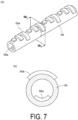
- a stationary mixer 56 formed in a cylindrical shape is arranged inside the piping coupling the third distributor 62 and the hot runner 26, that is, the third distributor 62 and the first sprue runner 44 and the second sprue runner 46.
- the piping in which the stationary mixer 56 is arranged is coupled to the first sprue runner 44 and the second sprue runner 46 by way of a sprue bush 26d.
- a plurality of protrusions 56a are formed along the axial direction of the stationary mixer 56 on the outer surface and the inner surface of the stationary mixer 56 formed in a cylindrical shape.
- the protrusions 56a are formed along the circumferential direction of the stationary mixer 56, and the lengths of the protrusions 56a adjacent to each other along the axial direction of the stationary mixer 56 are different.
- three protrusions 56a having different circumferential lengths are repeatedly formed along the axial direction.
- the recycled material RC and the virgin material VM flowing through the piping are disturbed by the protrusions 56a of the stationary mixer 56. For this reason, in a case where the recycled material RC and the virgin material VM are mixed and flow through the piping, the recycled material RC and the virgin material VM are disturbed and are promoted to be mixed with each other.
- the material of the injection material when the recycled material RC and the virgin material VM are mixed and injection molded can be homogenized.
- the shape of the protrusion 56a illustrated in the present embodiment is an example, and this is not the sole case, and protrusions having different shapes may be formed as long as they are molded to an extent the composite material can be disturbed.
- a servomotor 58 (an example of an adjustment device) for actuating, that is, sliding a stem 50, to be described later, is disposed inside the control plate 26b.
- the servomotor 58 is electrically connected to the control device 30.
- the nozzle 42 is formed in a bell shape whose outer peripheral shape is reduced in diameter toward the mold M, and an injection port 48 for injecting a material, that is, a resin is formed at a distal end portion facing the mold M. Furthermore, the center portion of the nozzle 42 is formed with a first injection path 52 along the axial direction thereof, and an end portion is connected to the injection port 48. In addition, on the radially outward side of the first injection path 52 is formed a second injection path 54 in the axial direction of the nozzle 42 and along the outer periphery of the first injection path 52, and the end portion is connected to the injection port 48.
- the first injection path 52 is connected with the first sprue runner 44 and the second injection path 54 is connected with the second sprue runner 46.
- a stem 50 made of metal and formed in a rod shape is disposed along the axial direction of the nozzle 42.
- the stem 50 is configured to be slidable along the axial direction of the nozzle 42 by a servomotor 58 (see FIG. 6(b) ). Therefore, the control device 30 can control the sliding, that is, the movement amount of the stem 50 by controlling, that is, actuating, the servomotor 58.
- the first injection path 52 can be blocked or opened, and the amount of recycled material RC and/or virgin material VM to be injected from the first injection path 52 can be adjusted. Note that it is not necessary to provide the same number of servomotors 58 as the number of stems 50, and several stems 50 may be connected to one servomotor 58, and these stems 50 may be simultaneously moved by the servomotor 58.
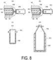
- the first injection path 52 is blocked by sliding the stem 50 toward the injection port 48 side.
- the virgin material VM is pressurized by the second plunger 40 and injected from the second injection path 54 to the mold M (see FIG. 3 ).
- the injected virgin material VM first comes into contact with the inner side portion of the mold M, and this contact portion is cooled and solidified. Therefore, the subsequently injected virgin material VM flows along the inner side of the mold M starting from this portion.
- the stem 50 is slid toward the hot runner 26, that is, toward the side away from the injection port 48 to open the first injection path 52.
- the pressurization of the second plunger 40 is stopped and the recycled material RC is pressurized by the first plunger 34, only the recycled material RC is injected into the mold M from the first injection path 52. Therefore, as illustrated in FIG. 8(c) , the first preform 101 in which the virgin material VM is disposed on the inner side and at the bottom portion can be configured. Furthermore, as illustrated in FIG.
- the first preform 101 is expanded by stretch blow molding, whereby the plastic container PB in which the virgin material VM is disposed on the inner side and at the bottom portion can be molded.
- the plastic container PB in which the recycled material RC and the virgin material VM are used in combination so that high quality can be secured, that is, the influence on the contents such as beverages to be injected into the container can be suppressed or prevented and the strength of the container can be secured.
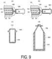
- the first plunger 34 is connected to the second plunger 40 by way of the first distributor 60 and the second distributor 64. Therefore, the virgin material VM on the second plunger 40 side can flow to the first plunger 34 side, and be mixed with the recycled material RC of the first plunger 34 thus creating the mixed material MX.
- the first injection path 52 is blocked by sliding the stem 50 toward the injection port 48 side.
- the virgin material VM created on the second plunger 40 side is pressurized and injected from the second injection path 54 to the mold M (see FIG. 3 ).
- the injected virgin material VM first comes into contact with the inner side portion of the mold M, and this contact portion is cooled and solidified. Therefore, the subsequently injected virgin material VM flows along the inner side of the mold M starting from this portion.
- the stem 50 is slid toward the hot runner 26 to open the first injection path 52.
- the pressurization of the second plunger 40 is stopped and the mixed material MX is pressurized by the first plunger 34, only the mixed material MX can be injected into the mold M from the first injection path 52. Therefore, as illustrated in FIG. 9(c) , the second preform 102 in which the virgin material VM is disposed on the inner side and at the bottom portion can be configured. Furthermore, as illustrated in FIG.
- the second preform 102 configured in such a manner is expanded by stretch blow molding, whereby the plastic container PB in which the virgin material VM is disposed on the inner side and at the bottom portion can be molded.
- the plastic container PB in which the recycled material RC and the virgin material VM are used in combination so that high quality can be secured, that is, the influence on the contents such as beverages to be injected into the container can be suppressed or prevented and the strength of the container can be secured.
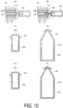
- the first injection path 52 is blocked by sliding the stem 50 toward the injection port 48 side.
- the recycled material RC on the first plunger 34 side is pressurized, and a large amount of the recycled material RC is injected from the second injection path 54 into the mold M (see FIG. 3 ).
- the large amount of the injected recycled material RC flows into the back of the mold M without being solidified even when coming into contact with the inner side portion of the mold M.
- the stem 50 is slid toward the hot runner 26 to open the first injection path 52.
- the pressurization of the first plunger 34 is stopped and the virgin material VM is pressurized by the second plunger 40, only the virgin material VM can be injected into the mold M from the first injection path 52. Therefore, as illustrated in FIG. 10(c) , since the recycled material RC is swept away to the back of the mold M, the third preform 103 in which the virgin material VM is disposed at the bottom portion and the recycled material RC is disposed at the top portion can be configured.
- the fourth preform 104 in which the virgin material VM is disposed at the bottom portion and the mixed material MX is disposed at the top portion can be configured by creating the mixed material MX on the first plunger 34 side and injecting the mixed material MX into the mold M.
- the plastic container PB in which the virgin material VM is disposed at the bottom portion can be molded by expanding the third preform 103 and the fourth preform 104 by stretch blow molding. As a result, the plastic container PB using the recycled material RC and the virgin material VM in combination so as to ensure high quality can be manufactured.
- FIG. 11(a) illustrates a modified example 103A of the third preform 103.
- a recycled material RC is disposed at the top portion, and a two-layer structure of the recycled material RC (inner side) and a virgin material VM (outer side) is formed at the bottom portion.
- a plastic container PB FIG. 11(b) ) obtained by expanding the modified example 103A by stretch blow molding, the recycled material RC is disposed on the inner side of the bottom portion, and the virgin material VM is disposed on the outer side of the bottom portion.
- a configuration in which the bottom portion is partially made of the virgin material VM as in the modified example 103A can also be adopted.
- FIG. 12 illustrates an injection method using a single nozzle 90 as a nozzle with a single injection path. Only a first injection path 92 is formed in the single nozzle 90, where the first injection path 92 is connected with the first sprue runner 44 and/or the second sprue runner 46 and can inject the mixed material MX created on the first plunger 34 and/or the second plunger 40 side.
- the fifth preform 105 can be made of the mixed material MX in which the composition of the virgin material VM is adjusted according to the intended use. Furthermore, as illustrated in FIG. 12(d) , the fifth preform 105 is expanded by stretch blow molding, whereby the plastic container PB in which the mixed material MX is disposed can be molded. As a result, the plastic container PB using the recycled material RC and the virgin material VM in combination so as to ensure high quality can be manufactured.
- the first plasticizing device 32 for melting the recycled material RC, the second plasticizing device 38 for melting the virgin material VM, and the first plunger 34 and the second plunger 40 for pressurizing the recycled material RC and the virgin material VM melted therein are provided.
- a hot runner 26 including a first sprue runner 44 which is connected to the first plunger 34 and the second plunger 40 via piping and in which a flow path through which the recycled material RC and the virgin material VM pressurized by the first plunger and the second plunger are passed is formed; and a nozzle 42 which is connected to a mold M installed in the mold mounting unit 28 and which injects the recycled material RC and the virgin material VM flowing in from the first sprue runner 44 into the mold M.
- materials having different physical properties such as the recycled material RC and the virgin material VM and thus having different heating times and heating temperatures required for melting can be individually melted.
- the high-quality plastic container PB can be manufactured while securing the quality of the recycled material RC and the virgin material VM.
- the first distributor 60 and the second distributor 64 that allow or shield the recycled material RC and/or the virgin material VM flowing from the first plasticizing device 32 and the second plasticizing device 38 to pass therethrough are provided. Therefore, the amount of molten material extruded by the first plunger 34 and the second plunger 40 can be adjusted according to the site of the plastic container PB to be injection molded. As a result, the molten material can be used for different purposes according to the site of the plastic container PB, and the high-quality plastic container PB can be manufactured.
- the recycled material RC can be used for at least one of the composite materials. Therefore, the high-quality plastic container PB can be manufactured by combining the recycled material RC and another material having different physical properties from the recycled material RC.
- the third distributor 62 that is disposed between the first distributor 60 and the first sprue runner 44, that is connected to the second plasticizing device 38 and the second plunger 40 via piping, and that allows or shields the recycled material RC and the virgin material VM is provided.
- the third distributor 62 is connected to the second sprue runner 46 of the hot runner 26 via piping.
- a cylindrical stationary mixer 56 that is arranged in the piping between the first sprue runner 44 and second sprue runner 46 and the third distributor 62, respectively, and in which the protrusion 56a is formed on the outer side portion is provided.
- the recycled material RC and the virgin material VM flowing via the third distributor 62 to the first sprue runner 44 and the second sprue runner 46 can be stirred by the protrusion 56a on the outer side of the stationary mixer 56. Therefore, the mixed material MX can flow to the first sprue runner 44 and the second sprue runner 46 in a homogeneous state. As a result, a high-quality plastic container PB can be manufactured.
- the second distributor 64 that is connected to the second plasticizing device 38 and the second plunger 40 via a piping and that allows or shields the virgin material VM to pass toward the first distributor 60 or the third distributor 62. Therefore, the amount of molten material extruded by the second plunger 40 can be adjusted according to the site of the plastic container PB to be injection molded. As a result, the molten material can be used for different purposes according to the site of the plastic container PB, and the high-quality plastic container PB can be manufactured.
- the hot runner 26 includes the stem 50 for opening and closing the nozzle 42, the servomotor 58 for actuating the nozzle 42, and the control plate 26b for arranging the servomotor 58.
- the amount of recycled material RC and virgin material VM to be injected via the first sprue runner 44 and the second sprue runner 46 can be adjusted by actuating the stem 50 to open and close the nozzle 42.
- the recycled material RC and the virgin material VM can be used for different purposes according to the site of the plastic container PB, a high-quality plastic container PB can be manufactured.
- the manufacturing system 10 includes the molding machine 14 and the decontamination machine 20 that decontaminates the recycled material RC. Therefore, a high-quality plastic container PB can be manufactured after decontaminating the recycled material RC to which the contaminants are attached.
- the plastic container PB made of the composite material of the recycled material RC and the virgin material VM can be manufactured so that high quality can be secured by the manufacturing system 10 according to the present embodiment.
- first plunger 34 and the second plunger 40 are used as the plungers here, no such limitation is intended, and the plungers may be integrated into one, or three or more plungers may be used.
- a first flow path 63b, a second flow path 63c, a third flow path 63d, and a fourth flow path 63e for circulating the recycled material RC and the virgin material VM are formed along the radial direction inside a main body 63a formed in a circular column shape. Furthermore, the third distributor 63 is slidable along its axial direction. The first flow path 63b and the second flow path 63c are formed in linear shapes orthogonal to each other when viewed along the axial direction of the main body 63a.
- the recycled material RC and/or the virgin material VM can flow to one of the first sprue runner 44 and the second sprue runner 46 and can flow to the other of the first sprue runner 44 and the second sprue runner 46 by rotating the main body 63a 90 degrees about the axial direction.
- the third flow path 63d and the fourth flow path 63e are curved flow paths that do not pass through the axial center of the main body 63a to flow only one of the recycled material RC and the virgin material VM from the first plunger 34 or the second plunger 40 to the first sprue runner 44 or the second sprue runner 46.
- the third distributor 63 may adjust the amount of recycled material RC and virgin material VM flowing from the first distributor 60 to the first sprue runner 44 and the amount of recycled material RC and virgin material VM flowing from the second plunger 40 to the first sprue runner 44. Furthermore, the third distributor 63 may adjust the amount of recycled material RC and virgin material VM flowing from the first distributor 60 to the second sprue runner 46 and the amount of recycled material RC and virgin material VM flowing from the second plunger 40 to the second sprue runner 46.
- molten materials can be injected via the first sprue runner 44 and the second sprue runner 46, and the molten material can be used for different purposes according to the site of the plastic container PB, so that a high-quality plastic container PB can be manufactured.
- a hot runner 26 is configured by sandwiching a control plate 26b and an oil plate 26e between a packing plate 26a and a manifold 26c.
- a magnetic displacement gauge 94 for detecting displacement of the stem 50 is disposed on the control plate 26b, and the oil plate 26e is configured to be able to actuate the drive mechanism 96 by hydraulic pressure in order to slide the stem 50.
- the magnetic displacement gauge 94 and the drive mechanism 96 are configured to interlock via the control device 30.
- the hot runner 26 includes a magnetic displacement gauge 94 that detects displacement of the stem 50, and an oil plate 26e (an example of a hydraulic device) that is connected to the magnetic displacement gauge 94 and actuates the drive mechanism 96 by hydraulic pressure. Therefore, the opening and closing of the nozzle 42 is adjusted while confirming the displacement of the stem 50 detected by the magnetic displacement gauge 94, and as a result, the amount of recycled material RC and the virgin material VM to be injected via the first sprue runner 44 and the second sprue runner 46 can be adjusted. As a result, it is possible to use the molten material to be injected for different purposes according to the site of the plastic container PB, so that a high-quality plastic container PB can be manufactured.
- a third injection section 70 is added to the manufacturing system 10 according to the above-described embodiment.
- the third injection section 70 includes a hopper 76 into which the pellet-like mixed material MX is charged, and a third plasticizing device 78.
- the third plasticizing device 78 has a screw (not shown) extending in the longitudinal direction inside a housing 78a thereof, and is heated by a heater.
- the distal end portion of the third plasticizing device 78 is connected to the first plasticizing device 32 via a piping, and the mixed material MX can be supplied to the first plasticizing device 32.
- the recycled material RC supplied from the decontamination machine 20 and the mixed material MX supplied from the third plasticizing device 78 can be mixed.
- FIG. 16 Another embodiment illustrated in FIG. 16 has a configuration in which the second injection section 24 is omitted from the other embodiment of FIG. 15 .
- the injection molding device according to the present invention may be implemented by a configuration including the injection section (first injection section 22) including the first plasticizing device (first plasticizing device 32), the second plasticizing device (third plasticizing device 78), the plunger (first plunger 34), and the distributor (first distributor 60).
- first injection section 22 including the first plasticizing device (first plasticizing device 32), the second plasticizing device (third plasticizing device 78), the plunger (first plunger 34), and the distributor (first distributor 60).
- the posture of the first plunger 34 a posture in which the first plasticizing device and the plunger are in fluid communication
- a posture in which the second plasticizing device and the plunger are in fluid communication a posture in which the plunger and the hot runner are in fluid communication
- the two types of materials can be mixed at an arbitrary ratio in the plunger.
- the present invention can be used, for example, for manufacturing a preform.
Landscapes
- Engineering & Computer Science (AREA)
- Mechanical Engineering (AREA)
- Manufacturing & Machinery (AREA)
- Injection Moulding Of Plastics Or The Like (AREA)
- Processing And Handling Of Plastics And Other Materials For Molding In General (AREA)
- Moulds For Moulding Plastics Or The Like (AREA)
Abstract
An injection molding device includes a first injection section (22), a second injection section (24), a mold mounting unit (28) and a hot runner (26), where a posture in which a first plasticizing device (32) and a first plunger (34) are in fluid communication and a posture in which the first plunger (34) and the hot runner (26) are in fluid communication can be selected as a posture of a first distributor (60), a posture in which a second plasticizing device (38) and a second plunger (40) are in fluid communication and a posture in which the second plunger (40) and the hot runner (26) are in fluid communication can be selected as a posture of a second distributor (64), and the hot runner (26) includes a first sprue runner (44), a second sprue runner (46), and a nozzle (42), the nozzle (42) being in fluid communication with both sprue runners and can be in fluid communication with the mold (M).
Description
- The present application relates to an injection molding device.
- From the standpoint of reducing the environmental load, there is a growing need to reuse recycled plastic containers.
Patent Document 1 discloses a preform manufacturing device that includes a decontamination machine that removes contaminants in thermoplastic resin flakes generated from a used plastic container, and an injection molding machine that performs injection molding of a thermoplastic resin supplied from the decontamination machine and manufactures a preform from the thermoplastic resin flakes. - Since recycled materials are derived from used materials which are different from each other in various conditions (application, shape, processing conditions, etc.) relating to their origins, variations in quality may be recognized as compared with virgin materials manufactured under uniform manufacturing conditions. Therefore, in order to manufacture a plastic container using a recycled material, it is necessary to take measures such as absorbing variations in quality on the raw material side by adjusting manufacturing conditions.
- As an example of such measures, it has been studied to manufacture plastic containers using recycled materials and virgin materials or the like in combination to ensure a predetermined quality. For example,
Patent Document 1 discloses a device for manufacturing a preform using a virgin material alone, a recycled material alone, or a mixture of a virgin material and a recycled material as a material. - Patent Document 1:
JP 2019-514728 T US 2019/126512 A ) - In order to use the mixture of the virgin material and the recycled material in the device of
Patent Document 1, it is necessary to mix the virgin material and the recycled material in advance and then supply the mixture to the device. Therefore, it is difficult to change the ratio between the virgin material and the recycled material during the manufacturing of the preform, and there is a possibility that the variation in the quality of the recycled material cannot be absorbed. - Therefore, in supplying a plurality of types of materials to a mold, it is necessary to realize an injection molding device that can easily adjust supply conditions such as a supply order and a supply ratio.
- A first injection molding device according to the present invention includes a first injection section including a first plasticizing device, a first plunger, and a first distributor connected to the first plasticizing device and the first plunger, a second injection section including a second plasticizing device, a second plunger, and a second distributor connected to the second plasticizing device and the second plunger;
a mold mounting unit, and a hot runner in fluid communication with the first injection section and the second injection section, wherein a posture in which the first plasticizing device and the first plunger are in fluid communication and a posture in which the first plunger and the hot runner are in fluid communication are selectable as a posture of the first distributor, a posture in which the second plasticizing device and the second plunger are in fluid communication and a posture in which the second plunger and the hot runner are in fluid communication are selectable as a posture of the second distributor, the hot runner includes a first sprue runner, a second sprue runner, and a nozzle; and the nozzle is provided in fluid communication with the first sprue runner and the second sprue runner, and in fluid communication with a mold mounted on the mold mounting unit. - A second injection molding device according to the present invention includes an injection section including a first plasticizing device, a second plasticizing device, a plunger, and a distributor, a mold mounting unit, and a hot runner in fluid communication with the injection section, wherein a posture in which the first plasticizing device and the plunger are in fluid communication, a posture in which the second plasticizing device and the plunger are in fluid communication, and a posture in which the plunger and the hot runner are in fluid communication are selectable as a posture of the distributor, the hot runner includes a first sprue runner, a second sprue runner, and a nozzle, and the nozzle is provided in fluid communication with the first sprue runner and the second sprue runner, and in fluid communication with a mold mounted on the mold mounting unit.
- According to these configurations, supply conditions such as a supply order and a supply ratio can be adjusted when supplying the first material supplied through the first plasticizing device and the second material supplied through the second plasticizing device to the mold. As a result, the quality of the obtained molded body is easily stabilized.
- Preferred aspects of the present invention will be described below. However, the scope of the present invention is not limited by the preferred aspects described below.
- Preferably, as one aspect, in the injection molding device according to the present invention, the first distributor and the second distributor are connected to each other, and a posture in which the first plunger is in fluid communication with at least one of the second plasticizing device and the second plunger is selectable as the postures of the first distributor and the second distributor.
- According to this configuration, since the first material supplied through the first plasticizing device and the second material supplied through the second plasticizing device can be mixed in the first plunger, the physical properties of the material can be easily adjusted.
- As one aspect, the injection molding device according to the present invention further preferably includes a control device configured to control operations of the first plunger and the second plunger.
- According to this configuration, it is easy to control the ratio of the first material and the second material to be supplied to the mold.
- Preferably, as one aspect, the injection molding device according to the present invention further preferably includes a first flow meter provided in a flow path between the first distributor and the hot runner; and a second flow meter provided in a flow path between the second distributor and the hot runner; wherein the control device is configured to control operations of the first plunger and the second plunger in accordance with an instruction value of the first flow meter and an instruction value of the second flow meter.
- According to this configuration, it is easy to perform control reflecting the operation state of the injection molding device.
- Preferably, as one aspect, the injection molding device according to the present invention further includes a first displacement gauge configured to detect a displacement of the plunger of the first piston and a second displacement gauge configured to detect a displacement of the plunger of the second piston, and the control device is preferably capable of controlling operations of the first plunger and the second plunger in accordance with an instruction value of the first displacement gauge and an instruction value of the second displacement gauge.
- According to this configuration, it is easy to perform control reflecting the operation state of the injection molding device.
- In the injection molding device according to the present invention, as one aspect, the hot runner preferably includes a stem configured to open and close the nozzle, and an adjustment device configured to adjust a position of the stem.
- According to this configuration, it is easy to control the order, timing, ratio, and the like at which the first material and the second material are supplied to the mold.
- Preferably, in the injection molding device according to the present invention, as one aspect, the adjustment device preferably includes a servomotor and is configured to adjust the position of the stem in accordance with a rotational speed of the servomotor.
- According to this configuration, it is easy to finely adjust the order, timing, ratio, and the like at which the first material and the second material are supplied to the mold.
- Preferably, as one aspect, in the injection molding device according to the present invention, the adjustment device includes a magnetic displacement gauge and a hydraulic device configured to move the stem, and the hydraulic device is controlled in accordance with an instruction value of the magnetic displacement gauge.
- According to this configuration, it is easy to finely adjust the order, timing, ratio, and the like at which the first material and the second material are supplied to the mold.
- Preferably, as one aspect, the injection molding device according to the present invention further includes a third distributor provided between the hot runner and each of the first injection section and the second injection section, wherein as a posture of the third distributor, a posture in which the first injection section and the first sprue runner are in fluid communication and the second injection section and the second sprue runner are in fluid communication, and a posture in which the first injection section and the second sprue runner are in fluid communication, and the second injection section and the first sprue runner are in fluid communication are selectable.
- According to this configuration, the material to be supplied to the first sprue runner and second sprue runner can be arbitrarily selected.
- As one aspect, the injection molding device according to the present invention further preferably includes a stationary mixer provided in a flow path between the first plunger and the hot runner.
- According to this configuration, the material supplied from the first plunger to the hot runner can be easily made to a uniform state.
- As one aspect, the injection molding device according to the present invention further preferably includes a third plasticizing device, and a posture in which the third plasticizing device and the first plunger are in fluid communication is further selectable as the posture of the first distributor.
- According to this configuration, since the first material supplied through the first plasticizing device and the third material supplied through the third plasticizing device can be mixed in the first plunger, the physical properties of the material can be easily adjusted.
- As one aspect, the injection molding device according to the present invention is preferably provided with a raw material supply unit configured to supply a resin in a molten state to the first plasticizing device.
- According to this configuration, the material subjected to pre-treatment in the molten state can be supplied to the first plasticizing device.
- Preferably, as one aspect, in the injection molding device according to the present invention, the raw material supply unit includes an extruder configured to melt and extrude a recycled material and a decontamination machine configured to remove a foreign matter contained in the recycled material.
- According to this configuration, the decontamination treated recycled material can be used as the first material to be supplied through the first plasticizing device.
- As one aspect, in the injection molding device according to the present invention, a flake-like recycled material can be preferably used as the recycled material.
- According to this configuration, the step of pelletizing the recycled material can be omitted.
- Further features and advantages of the present invention will become more apparent from the following description of exemplary and non-limiting embodiments with reference to the drawings.
-
-
FIG. 1 illustrates a preform for a plastic container. -
FIG. 2 is a schematic view of a pre-treatment unit according to a first embodiment. -
FIG. 3 is a schematic view of an injection molding device according to the first embodiment. -
FIG. 4(a) illustrates a perspective view of the first distributor,FIG. 4(b) illustrates a cross-sectional view taken along line b-b ofFIG. 4(a), FIG. 4(c) illustrates a cross-sectional view taken along line c-c ofFIG. 4(a), and FIG. 4(d) illustrates a cross-sectional view taken along line d-d ofFIG. 4(a) . -
FIG. 5 illustrates a perspective view of a third distributor. -
FIG. 6(a) is an exploded perspective view of a hot runner, andFIG. 6(b) is a schematic view for explaining a relationship between a stem and a control plate. -
FIG. 7(a) is a perspective view of a stationary mixer, andFIG. 7(b) is a cross-sectional view taken along plane b-b ofFIG. 7(a) . -
FIG. 8(a) illustrates injection of a first resin of a first preform according to the present embodiment,FIG. 8(b) illustrates injection of a next resin,FIG. 8(c) illustrates a molded first preform, andFIG. 8(d) illustrates a plastic bottle manufactured from the first preform. -
FIG. 9(a) illustrates injection of a first resin related to a second preform,FIG. 9(b) illustrates injection of a next resin,FIG. 9(c) illustrates a molded second preform, andFIG. 9(d) illustrates a plastic bottle manufactured from the second preform. -
FIG. 10(a) illustrates injection of a first resin related to third and fourth preforms,FIG. 10(b) illustrates injection of a next resin,FIG. 10(c) illustrates a molded third preform,FIG. 10(d) illustrates a plastic bottle manufactured from the third preform,FIG. 10(e) illustrates a molded fourth preform, andFIG. 10(f) illustrates a plastic bottle manufactured from the fourth preform. -
FIG. 11(a) illustrates a modified example of the third preform,FIG. 11(b) illustrates a plastic bottle manufactured from the modified example of the third preform,FIG. 11(c) illustrates a modified example of the fourth preform, andFIG. 11(d) illustrates a plastic bottle manufactured from the modified example of the fourth preform. -
FIG. 12(a) illustrates injection of a first resin related to a fifth preform,FIG. 12(b) illustrates injection of a next resin,FIG. 12(c) illustrates a molded fifth preform, andFIG. 12(d) illustrates a plastic bottle manufactured from the fifth preform. -
FIG. 13(a) is a perspective view of a third distributor according to a modified example,FIG. 13(b) is a cross-sectional view taken along line b-b ofFIG. 13(a), FIG. 13(c) is a cross-sectional view taken along line c-c ofFIG. 13(a), FIG. 13(d) is a cross-sectional view taken along line d-d ofFIG. 13(a), and FIG. 13(e) is a cross-sectional view taken along line e-e ofFIG. 13(a) . -
FIG. 14(a) is an exploded perspective view of a hot runner according to a modified example, andFIG. 14(b) is a schematic view for explaining a relationship between a stem, a control plate, and an oil plate. -
FIG. 15 is a schematic view of an injection molding device according to another embodiment. -
FIG. 16 is a schematic view of an injection molding device according to another embodiment. - An embodiment of an injection molding device according to the present invention will be described with reference to the drawings. Hereinafter, an example in which the injection molding device according to the present invention is applied to a manufacturing system 10 (an example of an injection molding device) that manufactures a preform 100 (
FIG. 1 ) to be used for manufacturing of plastic bottles will be described. Note that the same or corresponding elements are denoted by the same reference numerals, and redundant description will be omitted. In order to facilitate understanding, the scale of the drawings may be changed. -
FIG. 1 illustrates apreform 100 for a plastic container. Here, the plastic container is a plastic bottle which is mainly used to accommodate beverages, foods, and the like, and is made of polyethylene terephthalate (PET). The plastic container is not limited thereto, and may be made of plastic such as polypropylene (PP) or polyethylene (PE). The plastic container may also be polyethylene naphthalate (PEN), in particular a plant bottle made from a plant or the like. - The
preform 100 has a shape like a test tube including amouth portion 100a fitted with a cap of a plastic container, acylindrical body portion 100b formed in continuation with themouth portion 100a, and abottom portion 100c that closes one end portion of the cylindrical body portion. One end portion of themouth portion 100a is opened, and the outer peripheral surface thereof is formed with a male screw to be screwed with a female screw formed on the cap of the plastic container. The plastic container is molded by expanding a test tube-shapedpreform 100 by stretch blow molding. -
FIGS. 2 and3 show schematic views of amanufacturing system 10. As shown inFIG. 2 , themanufacturing system 10 includes apre-treatment unit 12 for pre-treatment a recycled material RC as a first molten material, and amolding machine 14 as shown inFIG. 3 . Thepreform 100 is generally manufactured using themolding machine 14 by using a virgin material VM serving as a second molten material containing petroleum or the like as a raw material, a recycled material RC containing used plastic container as a raw material, or a composite material such as a mixture of the virgin material VM and the recycled material RC as a raw material. Since the used plastic container may be contaminated with impurities, the recycled material RC is charged into themolding machine 14 after the impurities are removed in advance by thepre-treatment unit 12. In the following description, the composite material is described as the virgin material VM and the recycled material RC, but no such limitation is intended, and for example, a plastic container may be manufactured by a composite material of a petroleum-derived plastic material and a bioplastic material. - Note that, instead of the virgin material VM, a recycled material, such as bioplastic or chemical recycled plastic, from which a material having a relatively stable quality can be easily obtained, may be used. Since the virgin material VM or an alternative material is supplied to a
second plasticizing device 38 via ahopper 36 as will be described later, it is preferable that a material is in a form suitable for supply from thehopper 36 such as a pellet form or a powder form. Regarding the chemical recycled plastics and the like exemplified above, commercially available products in pellet form or powder form are available, and the material can be pelletized or powdered through a known method. - The
pre-treatment unit 12 serving as an example of a raw material supply unit includes adryer 16, anextruder 18, and adecontamination machine 20. The recycled material RC is a thermoplastic resin flake serving as an example of a flake-like recycled material, for example, a PET flake obtained by washing and then pulverizing a used PET bottle (a washing machine and a pulverizer are not shown). Here, the PET flakes are assumed to be small pieces of about 8 mm square. The recycled material RC is charged into a tank of thedryer 16, dried in thedryer 16, and then supplied to theextruder 18. - The recycled material RC dried in the
dryer 16 is sent to theextruder 18 and heated while being stirred. Therefore, the recycled material RC is melted and plasticized. Note that in addition to the recycled material RC, the virgin material VM may be supplied to theextruder 18. In this case, the supply position of the virgin agent VM may be thedryer 16 or theextruder 18. - The recycled material RC plasticized in the
extruder 18 is sent to thedecontamination machine 20. Thedecontamination machine 20 interiorly includes a decontamination container connected to a vacuum pump, and can volatilize contaminants in the recycled material RC, that is, in the thermoplastic resin by heating the recycled material RC charged into the decontamination container under vacuum. Thus, contaminants in the recycled material RC can be removed. Note that both the vacuum pump and the decontamination container are not illustrated. - The decontaminated recycled material RC is supplied to a
molding machine 14. As illustrated inFIG. 3 , the moldingmachine 14 includes afirst injection section 22, asecond injection section 24, ahot runner 26, amold mounting unit 28, and acontrol device 30. Note that a mold M is mounted on themold mounting unit 28. Furthermore, the mold M is provided with a plurality of cavities in correspondence with the shape of apreform 100, and a plurality ofpreforms 100 can be manufactured by one injection molding. - The
first injection section 22 includes afirst plasticizing device 32, afirst plunger 34, and afirst distributor 60. Thefirst plasticizing device 32 has a screw (not shown) extending in the longitudinal direction inside ahousing 32a thereof, and is heated by a heater. The thermoplastic resin of the recycled material RC supplied from thedecontamination machine 20 is supplied in a molten state to the inside of thefirst plasticizing device 32, and is stirred in a heated state, so that a plasticized state can be maintained. - A distal end portion of the
first plasticizing device 32 is coupled with thefirst plunger 34 by way of thefirst distributor 60. Thefirst plunger 34 has, on the inner side, afirst piston 34a configured to be slidable along the longitudinal direction of thefirst plunger 34. The recycled material RC in thefirst plasticizing device 32 is sucked up into thefirst plunger 34 by sliding thefirst piston 34a in the direction of pulling out from thefirst plunger 34. Furthermore, the recycled material RC sucked up into thefirst plunger 34 can be pressurized, that is, extruded toward thehot runner 26 by sliding thefirst piston 34a in a direction of pushing into thefirst plunger 34. Thefirst plunger 34 is connected to thecontrol device 30, and is configured to control the amount of recycled material RC to be extruded from thefirst plunger 34 by controlling the sliding, that is, the movement amount of thefirst plunger 34. - The
first distributor 60 is coupled to thehot runner 26 by way of athird distributor 62 to be described later. Thus, the recycled material RC extruded by thefirst plunger 34 is configured to flow into thehot runner 26 through thethird distributor 62. - The molding
machine 14 includes thesecond injection section 24 for supplying the virgin material VM to the mold M installed in themold mounting unit 28, and thesecond injection section 24 includes ahopper 36 into which the pellet-like virgin material VM is charged, asecond plasticizing device 38, asecond plunger 40, and asecond distributor 64. Thesecond plasticizing device 38 has a screw (not shown) extending in the longitudinal direction inside ahousing 38a thereof, and is heated by a heater. The thermoplastic resin of the virgin material VM supplied in a pellet state from thehopper 36 is plasticized by being stirred in a heated state in thesecond plasticizing device 38. - A distal end portion of the
second plasticizing device 38 is coupled with thesecond plunger 40 by way of thesecond distributor 64. Thesecond plunger 40 has, on the inner side, asecond piston 40a configured to be slidable along the longitudinal direction of thesecond plunger 40. The virgin material VM in thesecond plasticizing device 38 is sucked up into thesecond plunger 40 by sliding thesecond piston 40a in the direction of pulling out from thesecond plunger 40. The virgin material VM sucked up into thesecond plunger 40 can be pressurized, that is, extruded toward thehot runner 26 by sliding thesecond piston 40a in a direction of pushing into thesecond plunger 40. Thesecond plunger 40 is connected to thecontrol device 30, and is configured to control the amount of virgin material VM to be extruded from thesecond plunger 40 by controlling the sliding, that is, the movement amount of thesecond plunger 40. - The
second distributor 64 is coupled to thehot runner 26 by way of athird distributor 62 to be described later. Thus, the virgin material VM extruded by thesecond plunger 40 is configured to flow into thehot runner 26 through thethird distributor 62. - The
first distributor 60 and thesecond distributor 64 are coupled to each other via piping 65, which allows thefirst plunger 34 and thesecond plunger 40 to be in fluid communication. Thus, the virgin material VM in thesecond plunger 40 can flow to thefirst plunger 34 via thesecond distributor 64, the piping 65, and thefirst distributor 60, and the recycled material RC supplied from thefirst plasticizing device 32 and the virgin material VM supplied from thesecond plasticizing device 38 via thesecond plunger 40 can be mixed. Conversely, the recycled material RC can also be supplied to thesecond plunger 40. - As illustrated in
FIG. 4 , thefirst distributor 60 has a shape in which afirst flow path 60b, asecond flow path 60c, and athird flow path 60d for circulating the recycled material RC and the virgin material VM are formed to be spaced apart from each other in the axial direction inside a cylindricalmain body 60a. By sliding themain body 60a in the axial direction, the posture of any one of thefirst flow path 60b, thesecond flow path 60c, and thethird flow path 60d can be changed to align with two or three of thefirst plasticizing device 32, thefirst plunger 34, thesecond distributor 64, and thethird distributor 62 thereby achieving fluid communication according to the purpose. Since the shape and function of thesecond distributor 64 are similar to those of thefirst distributor 60, the description thereof will be omitted. - The
first flow path 60b has openings on three sides separated by 90° in the cross section of themain body 60a, and these openings are directed to thefirst plasticizing device 32, thefirst plunger 34, and thesecond distributor 64, respectively, so that the three can be in fluid communication. At this time, when the posture in which thefirst distributor 60 and thesecond plunger 40 are in fluid communication is selected as the posture of thesecond distributor 64, thefirst plasticizing device 32, thefirst plunger 34, and thesecond plunger 40 are in fluid communication. In this state, the recycled material RC supplied from thefirst plasticizing device 32 and the virgin material VM supplied from thesecond plasticizing device 38 via thesecond plunger 40 can be guided to thefirst plunger 34. - The
second flow path 60c has openings on two sides separated by 180° in the cross section of themain body 60a, and these openings are directed to thefirst plunger 34 and thehot runner 26, respectively, so that the two can be in fluid communication. However, in the present embodiment, since thethird distributor 62 is provided between thefirst distributor 60 and thehot runner 26, thefirst distributor 60 and thethird distributor 62 are in fluid communication. In this state, the material can be injected from thefirst plunger 34 to thehot runner 26. - The
third flow path 60d has openings on two sides separated by 90° in the cross section of themain body 60a, and these openings are directed to thefirst plasticizing device 32 and thefirst plunger 34, respectively, so that the two can be in fluid communication. In this state, the recycled material RC supplied from thefirst plasticizing device 32 can be guided to thefirst plunger 34. -
FIG. 5 is a perspective view of athird distributor 62. Thethird distributor 62 is formed in a circular column shape and is coupled to thefirst distributor 60 and thesecond distributor 64 by way of piping (seeFIG. 3 ). Thethird distributor 62 is arranged such that its axial direction is orthogonal to the axial direction of the piping coupling thethird distributor 62 and thefirst distributor 60 and thesecond distributor 64, that is, the direction in which the recycled material RC and the virgin material VM flow through the piping. Furthermore, thethird distributor 62 is configured to be slidable along the axial direction thereof by a drive mechanism (not illustrated). - The
third distributor 62 has throughholes holes holes holes holes - The
third distributor 62 can switch between the throughholes first distributor 60 and thesecond distributor 64 by sliding along the axial direction. Specifically, when coupled with a piping on one side of thethird distributor 62, the throughhole 62a and thefirst distributor 60 are connected to each other, and the throughhole 62b and thesecond distributor 64 are connected to each other. Furthermore, when thethird distributor 62 is slid and coupled on the other side, the throughhole 62d and thefirst distributor 60 are connected to each other, and the throughhole 62c and thesecond distributor 64 are connected to each other. By sliding thethird distributor 62 in this way, it is possible to switch between thefirst distributor 60 and thesecond distributor 64, that is, the piping coupling thefirst injection section 22 and thesecond injection section 24 and thehot runner 26. Furthermore, by sliding thethird distributor 62 to a position where the throughholes first injection section 22 and thesecond injection section 24 can be shielded. - The control of the operation of the
first plunger 34 and thesecond plunger 40 by thecontrol device 30 is performed in accordance with, for example, the flow rate of the material extruded from each plunger and the displacement of the piston of each plunger. In the former example, the operation of each of thefirst plunger 34 and thesecond plunger 40 is controlled in accordance with instruction values of a first flow meter (not illustrated) provided in the flow path between thefirst distributor 60 and thehot runner 26 and a second flow meter (not illustrated) provided in the flow path between thesecond distributor 64 and thehot runner 26. As a result, for example, the ratio of the material injected from each of thefirst plunger 34 and thesecond plunger 40 to the mold M, the mixing ratio when mixing the two types of materials in thefirst plunger 34, and the like can be controlled. In the latter example, the flow rate of the material can be specified based on the displacement of the piston of each plunger, and the same control as in the former example can be performed. - As illustrated in
FIG. 3 , thehot runner 26 is provided with a plurality ofnozzles 42 for injecting the plasticized recycled material RC and the virgin material VM into the mold M installed in themold mounting unit 28. In addition. inside thehot runner 26, afirst sprue runner 44 and asecond sprue runner 46 for allowing thermoplastic resin to flow are formed as separate and independent flow paths. - When the
first distributor 60 and thesecond distributor 64 and the throughholes third distributor 62 are connected, the recycled material RC and/or the virgin material VM extruded from thefirst plunger 34 flow to thefirst sprue runner 44. In addition, the recycled material RC and/or the virgin material VM extruded from thesecond plunger 40 flow to thesecond sprue runner 46. - In contrast, when the
first distributor 60 and thesecond distributor 64 and the throughholes third distributor 62 are coupled, the recycled material RC and/or the virgin material VM extruded from thesecond plunger 40 flow to thefirst sprue runner 44. In addition, the recycled material RC and/or the virgin material VM extruded from thefirst plunger 34 flow to thesecond sprue runner 46. - As illustrated in
FIG. 6(a) , thehot runner 26 is configured by overlapping apacking plate 26a and a manifold 26c, and is interiorly disposed with thefirst sprue runner 44 and the second sprue runner 46 (seeFIG. 3 for both). Furthermore, acontrol plate 26b is sandwiched between the packingplate 26a and the manifold 26c. - Inside the piping coupling the
third distributor 62 and thehot runner 26, that is, thethird distributor 62 and thefirst sprue runner 44 and thesecond sprue runner 46, astationary mixer 56 formed in a cylindrical shape is arranged. The piping in which thestationary mixer 56 is arranged is coupled to thefirst sprue runner 44 and thesecond sprue runner 46 by way of asprue bush 26d. As illustrated inFIG. 7 , a plurality ofprotrusions 56a are formed along the axial direction of thestationary mixer 56 on the outer surface and the inner surface of thestationary mixer 56 formed in a cylindrical shape. Theprotrusions 56a are formed along the circumferential direction of thestationary mixer 56, and the lengths of theprotrusions 56a adjacent to each other along the axial direction of thestationary mixer 56 are different. Here, threeprotrusions 56a having different circumferential lengths are repeatedly formed along the axial direction. The recycled material RC and the virgin material VM flowing through the piping are disturbed by theprotrusions 56a of thestationary mixer 56. For this reason, in a case where the recycled material RC and the virgin material VM are mixed and flow through the piping, the recycled material RC and the virgin material VM are disturbed and are promoted to be mixed with each other. As a result, the material of the injection material when the recycled material RC and the virgin material VM are mixed and injection molded can be homogenized. Note that the shape of theprotrusion 56a illustrated in the present embodiment is an example, and this is not the sole case, and protrusions having different shapes may be formed as long as they are molded to an extent the composite material can be disturbed. - As illustrated in
FIG. 6(b) , a servomotor 58 (an example of an adjustment device) for actuating, that is, sliding astem 50, to be described later, is disposed inside thecontrol plate 26b. Theservomotor 58 is electrically connected to thecontrol device 30. - As shown in
FIGS. 3 and8(a) , thenozzle 42 is formed in a bell shape whose outer peripheral shape is reduced in diameter toward the mold M, and aninjection port 48 for injecting a material, that is, a resin is formed at a distal end portion facing the mold M. Furthermore, the center portion of thenozzle 42 is formed with afirst injection path 52 along the axial direction thereof, and an end portion is connected to theinjection port 48. In addition, on the radially outward side of thefirst injection path 52 is formed asecond injection path 54 in the axial direction of thenozzle 42 and along the outer periphery of thefirst injection path 52, and the end portion is connected to theinjection port 48. Thefirst injection path 52 is connected with thefirst sprue runner 44 and thesecond injection path 54 is connected with thesecond sprue runner 46. - Inside the
first injection path 52, astem 50 made of metal and formed in a rod shape is disposed along the axial direction of thenozzle 42. Thestem 50 is configured to be slidable along the axial direction of thenozzle 42 by a servomotor 58 (seeFIG. 6(b) ). Therefore, thecontrol device 30 can control the sliding, that is, the movement amount of thestem 50 by controlling, that is, actuating, theservomotor 58. Thus, thefirst injection path 52 can be blocked or opened, and the amount of recycled material RC and/or virgin material VM to be injected from thefirst injection path 52 can be adjusted. Note that it is not necessary to provide the same number ofservomotors 58 as the number of stems 50, and several stems 50 may be connected to oneservomotor 58, and these stems 50 may be simultaneously moved by theservomotor 58. - Next, an injection method for molding a
first preform 101 to a fifth preform 105 using the recycled material RC and the virgin material VM as the composite material through themanufacturing system 10 according to the present embodiment will be described. - Here, by adjusting, that is, sliding the
third distributor 62, thefirst plunger 34 and thefirst sprue runner 44 are connected to each other, and thesecond plunger 40 and thesecond sprue runner 46 are connected to each other. First, as illustrated inFIG. 8(a) , thefirst injection path 52 is blocked by sliding thestem 50 toward theinjection port 48 side. In this state, the virgin material VM is pressurized by thesecond plunger 40 and injected from thesecond injection path 54 to the mold M (seeFIG. 3 ). The injected virgin material VM first comes into contact with the inner side portion of the mold M, and this contact portion is cooled and solidified. Therefore, the subsequently injected virgin material VM flows along the inner side of the mold M starting from this portion. - Next, as illustrated in
FIG. 8(b) , thestem 50 is slid toward thehot runner 26, that is, toward the side away from theinjection port 48 to open thefirst injection path 52. In this state, when the pressurization of thesecond plunger 40 is stopped and the recycled material RC is pressurized by thefirst plunger 34, only the recycled material RC is injected into the mold M from thefirst injection path 52. Therefore, as illustrated inFIG. 8(c) , thefirst preform 101 in which the virgin material VM is disposed on the inner side and at the bottom portion can be configured. Furthermore, as illustrated inFIG. 8(d) , thefirst preform 101 is expanded by stretch blow molding, whereby the plastic container PB in which the virgin material VM is disposed on the inner side and at the bottom portion can be molded. As a result, it is possible to manufacture the plastic container PB in which the recycled material RC and the virgin material VM are used in combination so that high quality can be secured, that is, the influence on the contents such as beverages to be injected into the container can be suppressed or prevented and the strength of the container can be secured. - As illustrated in
FIG. 3 , thefirst plunger 34 is connected to thesecond plunger 40 by way of thefirst distributor 60 and thesecond distributor 64. Therefore, the virgin material VM on thesecond plunger 40 side can flow to thefirst plunger 34 side, and be mixed with the recycled material RC of thefirst plunger 34 thus creating the mixed material MX. - Here, by adjusting, that is, sliding the
third distributor 62, thefirst plunger 34 and thefirst sprue runner 44 are connected to each other, and thesecond plunger 40 and thesecond sprue runner 46 are connected to each other. First, as illustrated inFIG. 9(a) , thefirst injection path 52 is blocked by sliding thestem 50 toward theinjection port 48 side. In this state, the virgin material VM created on thesecond plunger 40 side is pressurized and injected from thesecond injection path 54 to the mold M (seeFIG. 3 ). The injected virgin material VM first comes into contact with the inner side portion of the mold M, and this contact portion is cooled and solidified. Therefore, the subsequently injected virgin material VM flows along the inner side of the mold M starting from this portion. - Next, as illustrated in
FIG. 9(b) , thestem 50 is slid toward thehot runner 26 to open thefirst injection path 52. In this state, when the pressurization of thesecond plunger 40 is stopped and the mixed material MX is pressurized by thefirst plunger 34, only the mixed material MX can be injected into the mold M from thefirst injection path 52. Therefore, as illustrated inFIG. 9(c) , the second preform 102 in which the virgin material VM is disposed on the inner side and at the bottom portion can be configured. Furthermore, as illustrated inFIG. 9(d) , the second preform 102 configured in such a manner is expanded by stretch blow molding, whereby the plastic container PB in which the virgin material VM is disposed on the inner side and at the bottom portion can be molded. As a result, it is possible to manufacture the plastic container PB in which the recycled material RC and the virgin material VM are used in combination so that high quality can be secured, that is, the influence on the contents such as beverages to be injected into the container can be suppressed or prevented and the strength of the container can be secured. - Here, by adjusting, that is, sliding the
third distributor 62, thefirst plunger 34 and thesecond sprue runner 46 are connected to each other, and thesecond plunger 40 and thefirst sprue runner 44 are connected to each other. First, as illustrated inFIG. 10(a) , thefirst injection path 52 is blocked by sliding thestem 50 toward theinjection port 48 side. In this state, the recycled material RC on thefirst plunger 34 side is pressurized, and a large amount of the recycled material RC is injected from thesecond injection path 54 into the mold M (seeFIG. 3 ). The large amount of the injected recycled material RC flows into the back of the mold M without being solidified even when coming into contact with the inner side portion of the mold M. - Next, as illustrated in
FIG. 10(b) , thestem 50 is slid toward thehot runner 26 to open thefirst injection path 52. In this state, when the pressurization of thefirst plunger 34 is stopped and the virgin material VM is pressurized by thesecond plunger 40, only the virgin material VM can be injected into the mold M from thefirst injection path 52. Therefore, as illustrated inFIG. 10(c) , since the recycled material RC is swept away to the back of the mold M, thethird preform 103 in which the virgin material VM is disposed at the bottom portion and the recycled material RC is disposed at the top portion can be configured. In addition, thefourth preform 104 in which the virgin material VM is disposed at the bottom portion and the mixed material MX is disposed at the top portion can be configured by creating the mixed material MX on thefirst plunger 34 side and injecting the mixed material MX into the mold M. Furthermore, as illustrated inFIGS. 10(d) and 10(f) , the plastic container PB in which the virgin material VM is disposed at the bottom portion can be molded by expanding thethird preform 103 and thefourth preform 104 by stretch blow molding. As a result, the plastic container PB using the recycled material RC and the virgin material VM in combination so as to ensure high quality can be manufactured. -
FIG. 11(a) illustrates a modified example 103A of thethird preform 103. In the modified example 103A, a recycled material RC is disposed at the top portion, and a two-layer structure of the recycled material RC (inner side) and a virgin material VM (outer side) is formed at the bottom portion. In a plastic container PB (FIG. 11(b) ) obtained by expanding the modified example 103A by stretch blow molding, the recycled material RC is disposed on the inner side of the bottom portion, and the virgin material VM is disposed on the outer side of the bottom portion. From the viewpoint of enhancing the strength of the bottom portion, in addition to the configuration in which the entire bottom portion is made of the virgin material VM as in thethird preform 103, a configuration in which the bottom portion is partially made of the virgin material VM as in the modified example 103A can also be adopted. The same applies to a modified example 104A (FIG. 11(c) ) of thefourth preform 104 and the plastic container PB (FIG. 11(d) ) obtained therefrom. -
FIG. 12 illustrates an injection method using a single nozzle 90 as a nozzle with a single injection path. Only afirst injection path 92 is formed in the single nozzle 90, where thefirst injection path 92 is connected with thefirst sprue runner 44 and/or thesecond sprue runner 46 and can inject the mixed material MX created on thefirst plunger 34 and/or thesecond plunger 40 side. - Therefore, as illustrated in
FIGS. 12(a) to 12(c) , the fifth preform 105 can be made of the mixed material MX in which the composition of the virgin material VM is adjusted according to the intended use. Furthermore, as illustrated inFIG. 12(d) , the fifth preform 105 is expanded by stretch blow molding, whereby the plastic container PB in which the mixed material MX is disposed can be molded. As a result, the plastic container PB using the recycled material RC and the virgin material VM in combination so as to ensure high quality can be manufactured. - Next, operations and effects of the
manufacturing system 10 according to the first embodiment will be described below. - According to the
manufacturing system 10 of the present embodiment, thefirst plasticizing device 32 for melting the recycled material RC, thesecond plasticizing device 38 for melting the virgin material VM, and thefirst plunger 34 and thesecond plunger 40 for pressurizing the recycled material RC and the virgin material VM melted therein are provided. In addition, there is provided ahot runner 26 including afirst sprue runner 44 which is connected to thefirst plunger 34 and thesecond plunger 40 via piping and in which a flow path through which the recycled material RC and the virgin material VM pressurized by the first plunger and the second plunger are passed is formed; and anozzle 42 which is connected to a mold M installed in themold mounting unit 28 and which injects the recycled material RC and the virgin material VM flowing in from thefirst sprue runner 44 into the mold M. For this reason, materials having different physical properties such as the recycled material RC and the virgin material VM and thus having different heating times and heating temperatures required for melting can be individually melted. As a result, the high-quality plastic container PB can be manufactured while securing the quality of the recycled material RC and the virgin material VM. - In addition, according to the
manufacturing system 10 of the present embodiment, thefirst distributor 60 and thesecond distributor 64 that allow or shield the recycled material RC and/or the virgin material VM flowing from thefirst plasticizing device 32 and thesecond plasticizing device 38 to pass therethrough are provided. Therefore, the amount of molten material extruded by thefirst plunger 34 and thesecond plunger 40 can be adjusted according to the site of the plastic container PB to be injection molded. As a result, the molten material can be used for different purposes according to the site of the plastic container PB, and the high-quality plastic container PB can be manufactured. - Furthermore, according to the
manufacturing system 10 of the present embodiment, the recycled material RC can be used for at least one of the composite materials. Therefore, the high-quality plastic container PB can be manufactured by combining the recycled material RC and another material having different physical properties from the recycled material RC. - In addition, according to the
manufacturing system 10 of the present embodiment, thethird distributor 62 that is disposed between thefirst distributor 60 and thefirst sprue runner 44, that is connected to thesecond plasticizing device 38 and thesecond plunger 40 via piping, and that allows or shields the recycled material RC and the virgin material VM is provided. Thus, it is possible to adjust the amount of recycled material RC and virgin material VM flowing from thefirst distributor 60 to thefirst sprue runner 44 and the amount of recycled material RC and virgin material VM flowing from thesecond plunger 40 to thefirst sprue runner 44. Thethird distributor 62 is connected to thesecond sprue runner 46 of thehot runner 26 via piping. Thus, it is possible to adjust the amount of recycled material RC and virgin material VM flowing from thefirst distributor 60 to thesecond sprue runner 46 and the amount of recycled material RC and virgin material VM flowing from thesecond plunger 40 to thesecond sprue runner 46. Thus, different molten materials can be injected via thefirst sprue runner 44 and thesecond sprue runner 46, and the molten material can be used for different purposes according to the site of the plastic container PB, so that a high-quality plastic container PB can be manufactured. - Further, according to the
manufacturing system 10 of the present embodiment, a cylindricalstationary mixer 56 that is arranged in the piping between thefirst sprue runner 44 andsecond sprue runner 46 and thethird distributor 62, respectively, and in which theprotrusion 56a is formed on the outer side portion is provided. Thus, the recycled material RC and the virgin material VM flowing via thethird distributor 62 to thefirst sprue runner 44 and thesecond sprue runner 46 can be stirred by theprotrusion 56a on the outer side of thestationary mixer 56. Therefore, the mixed material MX can flow to thefirst sprue runner 44 and thesecond sprue runner 46 in a homogeneous state. As a result, a high-quality plastic container PB can be manufactured. - In addition, according to the
manufacturing system 10 of the present embodiment, thesecond distributor 64 that is connected to thesecond plasticizing device 38 and thesecond plunger 40 via a piping and that allows or shields the virgin material VM to pass toward thefirst distributor 60 or thethird distributor 62. Therefore, the amount of molten material extruded by thesecond plunger 40 can be adjusted according to the site of the plastic container PB to be injection molded. As a result, the molten material can be used for different purposes according to the site of the plastic container PB, and the high-quality plastic container PB can be manufactured. - Furthermore, according to the
manufacturing system 10 of the present embodiment, thehot runner 26 includes thestem 50 for opening and closing thenozzle 42, theservomotor 58 for actuating thenozzle 42, and thecontrol plate 26b for arranging theservomotor 58. Thus, the amount of recycled material RC and virgin material VM to be injected via thefirst sprue runner 44 and thesecond sprue runner 46 can be adjusted by actuating thestem 50 to open and close thenozzle 42. As a result, since the recycled material RC and the virgin material VM can be used for different purposes according to the site of the plastic container PB, a high-quality plastic container PB can be manufactured. - In addition, according to the
manufacturing system 10 of the present embodiment, themanufacturing system 10 includes themolding machine 14 and thedecontamination machine 20 that decontaminates the recycled material RC. Therefore, a high-quality plastic container PB can be manufactured after decontaminating the recycled material RC to which the contaminants are attached. - As described above, the plastic container PB made of the composite material of the recycled material RC and the virgin material VM can be manufactured so that high quality can be secured by the
manufacturing system 10 according to the present embodiment. - Note that although the
first plunger 34 and thesecond plunger 40 are used as the plungers here, no such limitation is intended, and the plungers may be integrated into one, or three or more plungers may be used. - As illustrated in
FIG. 13 , in thethird distributor 63 according to the present modified example, afirst flow path 63b, asecond flow path 63c, athird flow path 63d, and afourth flow path 63e for circulating the recycled material RC and the virgin material VM are formed along the radial direction inside amain body 63a formed in a circular column shape. Furthermore, thethird distributor 63 is slidable along its axial direction. Thefirst flow path 63b and thesecond flow path 63c are formed in linear shapes orthogonal to each other when viewed along the axial direction of themain body 63a. For this reason, the recycled material RC and/or the virgin material VM can flow to one of thefirst sprue runner 44 and thesecond sprue runner 46 and can flow to the other of thefirst sprue runner 44 and thesecond sprue runner 46 by rotating themain body 63a 90 degrees about the axial direction. Furthermore, thethird flow path 63d and thefourth flow path 63e are curved flow paths that do not pass through the axial center of themain body 63a to flow only one of the recycled material RC and the virgin material VM from thefirst plunger 34 or thesecond plunger 40 to thefirst sprue runner 44 or thesecond sprue runner 46. - The
third distributor 63 may adjust the amount of recycled material RC and virgin material VM flowing from thefirst distributor 60 to thefirst sprue runner 44 and the amount of recycled material RC and virgin material VM flowing from thesecond plunger 40 to thefirst sprue runner 44. Furthermore, thethird distributor 63 may adjust the amount of recycled material RC and virgin material VM flowing from thefirst distributor 60 to thesecond sprue runner 46 and the amount of recycled material RC and virgin material VM flowing from thesecond plunger 40 to thesecond sprue runner 46. Thus, different molten materials can be injected via thefirst sprue runner 44 and thesecond sprue runner 46, and the molten material can be used for different purposes according to the site of the plastic container PB, so that a high-quality plastic container PB can be manufactured. - In the above embodiment, an example in which the
servomotor 58 is provided as the adjustment device for operating thestem 50 has been described. A modified example of such an adjustment device will be described below. - As illustrated in
FIG. 14(a) , ahot runner 26 according to the present modified example is configured by sandwiching acontrol plate 26b and anoil plate 26e between a packingplate 26a and a manifold 26c. As illustrated inFIG. 14(b) , amagnetic displacement gauge 94 for detecting displacement of thestem 50 is disposed on thecontrol plate 26b, and theoil plate 26e is configured to be able to actuate thedrive mechanism 96 by hydraulic pressure in order to slide thestem 50. Furthermore, themagnetic displacement gauge 94 and thedrive mechanism 96 are configured to interlock via thecontrol device 30. - The
hot runner 26 includes amagnetic displacement gauge 94 that detects displacement of thestem 50, and anoil plate 26e (an example of a hydraulic device) that is connected to themagnetic displacement gauge 94 and actuates thedrive mechanism 96 by hydraulic pressure. Therefore, the opening and closing of thenozzle 42 is adjusted while confirming the displacement of thestem 50 detected by themagnetic displacement gauge 94, and as a result, the amount of recycled material RC and the virgin material VM to be injected via thefirst sprue runner 44 and thesecond sprue runner 46 can be adjusted. As a result, it is possible to use the molten material to be injected for different purposes according to the site of the plastic container PB, so that a high-quality plastic container PB can be manufactured. - In another embodiment illustrated in
FIG. 15 , athird injection section 70 is added to themanufacturing system 10 according to the above-described embodiment. Thethird injection section 70 includes ahopper 76 into which the pellet-like mixed material MX is charged, and athird plasticizing device 78. Thethird plasticizing device 78 has a screw (not shown) extending in the longitudinal direction inside ahousing 78a thereof, and is heated by a heater. The distal end portion of thethird plasticizing device 78 is connected to thefirst plasticizing device 32 via a piping, and the mixed material MX can be supplied to thefirst plasticizing device 32. Thus, in thefirst plasticizing device 32, the recycled material RC supplied from thedecontamination machine 20 and the mixed material MX supplied from thethird plasticizing device 78 can be mixed. - Another embodiment illustrated in
FIG. 16 has a configuration in which thesecond injection section 24 is omitted from the other embodiment ofFIG. 15 . As described above, the injection molding device according to the present invention may be implemented by a configuration including the injection section (first injection section 22) including the first plasticizing device (first plasticizing device 32), the second plasticizing device (third plasticizing device 78), the plunger (first plunger 34), and the distributor (first distributor 60). In this case, as the posture of thefirst plunger 34, a posture in which the first plasticizing device and the plunger are in fluid communication, a posture in which the second plasticizing device and the plunger are in fluid communication, and a posture in which the plunger and the hot runner are in fluid communication may be selected. Thus, the two types of materials can be mixed at an arbitrary ratio in the plunger. - Also, with respect to other configurations, it should be understood that the embodiments described in the present specification are illustrative in all respects and that the scope of the present invention is not limited thereto. It will be easily understood by those skilled in the art that appropriate modifications can be made without departing from the spirit of the present invention. Accordingly, other embodiments modified without departing from the spirit of the present invention are naturally included in the scope of the present invention.
- The present invention can be used, for example, for manufacturing a preform.
-
- 10: Manufacturing system
- 12: Pre-treatment unit
- 14: Molding machine
- 16: Raw material pre-treatment unit
- 18: Extruder
- 20: Decontamination machine
- 22: First injection section
- 24: Second injection section
- 26: Hot runner
- 26a: Packing plate
- 26b: Control plate
- 26c: Manifold
- 26d: Sprue bush
- 26e: Oil plate
- 28: Mold mounting unit
- 30: Control device
- 32: First plasticizing device
- 32a: Housing
- 34: First plunger
- 34a: First piston
- 36: Hopper
- 38: Second plasticizing device
- 38a: Housing
- 40: Second plunger
- 40a: Second piston
- 42: Nozzle
- 44: First sprue runner
- 46: Second sprue runner
- 48: Injection port
- 50: Stem
- 52: First injection path
- 54: Second injection path
- 56: Stationary mixer
- 56a: Protrusion
- 58: Servomotor
- 60: First distributor
- 60a: Main body
- 60b: First flow path
- 60c: Second flow path
- 60d: Third flow path
- 62: Third distributor
- 62a: Through hole
- 62b: Through hole
- 62c: Through hole
- 62d: Through hole
- 63: Third distributor
- 63a: Main body
- 63b: First flow path
- 63c: Second flow path
- 63d: Third flow path
- 63e: Fourth flow path
- 64: Second distributor
- 65: Piping
- 70: Third injection section
- 76: Hopper
- 78: Third plasticizing device
- 78a: Housing
- 90: Single nozzle
- 92: First injection path
- 94: Magnetic displacement gauge
- 96: Drive mechanism
- M: Mold
- 100: Preform
- 100a: Mouth portion
- 100b: Cylindrical body portion
- 100c: Bottom portion
- 101: First preform
- 102: Second preform
- 103: Third preform
- 104: Fourth preform
- 105: Fifth preform
- MX: Mixed material
- RC: Recycled material
- VM: Virgin material
- PB: Plastic container
Claims (15)
- An injection molding device comprising:a first injection section including a first plasticizing device, a first plunger, and a first distributor connected to the first plasticizing device and the first plunger;a second injection section including a second plasticizing device, a second plunger, and a second distributor connected to the second plasticizing device and the second plunger;a mold mounting unit; anda hot runner in fluid communication with the first injection section and the second injection section; whereina posture in which the first plasticizing device and the first plunger are in fluid communication and a posture in which the first plunger and the hot runner are in fluid communication are selectable as a posture of the first distributor;a posture in which the second plasticizing device and the second plunger are in fluid communication and a posture in which the second plunger and the hot runner are in fluid communication are selectable as a posture of the second distributor;the hot runner includes a first sprue runner, a second sprue runner, and a nozzle; andthe nozzle is provided in fluid communication with the first sprue runner and the second sprue runner, and in fluid communication with a mold mounted on the mold mounting unit.
- The injection molding device according to claim 1, whereinthe first distributor and the second distributor are connected to each other, anda posture in which the first plunger is in fluid communication with at least one of the second plasticizing device and the second plunger is selectable as the postures of the first distributor and the second distributor.
- The injection molding device according to claim 1, further comprising a control device configured to control operations of the first plunger and the second plunger.
- The injection molding device according to claim 3, further comprising:a first flow meter provided in a flow path between the first distributor and the hot runner; anda second flow meter provided in a flow path between the second distributor and the hot runner, whereinthe control device is configured to control operations of the first plunger and the second plunger in accordance with an instruction value of the first flow meter and an instruction value of the second flow meter.
- The injection molding device according to claim 3, further comprising:a first displacement gauge configured to detect displacement of a piston of the first plunger; anda second displacement gauge configured to detect displacement of a piston of the second plunger, whereinthe control device is configured to control operations of the first plunger and the second plunger in accordance with an instruction value of the first displacement gauge and an instruction value of the second displacement gauge.
- The injection molding device according to any one of claims 1 to 5, wherein the hot runner includes a stem configured to open and close the nozzle, and an adjustment device configured to adjust a position of the stem.
- The injection molding device according to claim 6, wherein the adjustment device includes a servomotor and is configured to adjust the position of the stem in accordance with a rotational speed of the servomotor.
- The injection molding device according to claim 6, whereinthe adjustment device includes a magnetic displacement gauge and a hydraulic device configured to move the stem, andthe hydraulic device is controlled in accordance with an instruction value of the magnetic displacement gauge.
- The injection molding device according to claim 1, further comprising:a third distributor provided between the hot runner and each of the first injection section and the second injection section, whereinas a posture of the third distributor, a posture in which the first injection section and the first sprue runner are in fluid communication and the second injection section and the second sprue runner are in fluid communication, and a posture in which the first injection section and the second sprue runner are in fluid communication, and the second injection section and the first sprue runner are in fluid communication are selectable.
- The injection molding device according to claim 1, further comprising a stationary mixer provided in a flow path between the first plunger and the hot runner.
- The injection molding device according to claim 1, further comprising:a third plasticizing device, whereina posture in which the third plasticizing device and the first plunger are in fluid communication is further selectable as the posture of the first distributor.
- The injection molding device according to claim 1, further comprising a raw material supply unit configured to supply a resin in a molten state to the first plasticizing device.
- The injection molding device according to claim 12, wherein the raw material supply unit includes an extruder configured to melt and extrude a recycled material, and a decontamination machine configured to remove a foreign matter contained in the recycled material.
- The injection molding device according to claim 13, wherein a flake-like recycled material is usable as the recycled material.
- An injection molding device comprising:an injection section including a first plasticizing device, a second plasticizing device, a plunger, and a distributor;a mold mounting unit; anda hot runner in fluid communication with the injection section, whereina posture in which the first plasticizing device and the plunger are in fluid communication, a posture in which the second plasticizing device and the plunger are in fluid communication, and a posture in which the plunger and the hot runner are in fluid communication are selectable as a posture of the distributor;the hot runner includes a first sprue runner, a second sprue runner, and a nozzle, andthe nozzle is provided in fluid communication with the first sprue runner and the second sprue runner, and in fluid communication with a mold mounted on the mold mounting unit.
Applications Claiming Priority (2)
| Application Number | Priority Date | Filing Date | Title |
|---|---|---|---|
| JP2022090767 | 2022-06-03 | ||
| PCT/JP2023/018624 WO2023234058A1 (en) | 2022-06-03 | 2023-05-18 | Injection molding device |
Publications (1)
| Publication Number | Publication Date |
|---|---|
| EP4534271A1 true EP4534271A1 (en) | 2025-04-09 |
Family
ID=89026575
Family Applications (1)
| Application Number | Title | Priority Date | Filing Date |
|---|---|---|---|
| EP23815817.4A Pending EP4534271A1 (en) | 2022-06-03 | 2023-05-18 | Injection molding device |
Country Status (8)
| Country | Link |
|---|---|
| US (1) | US20250367867A1 (en) |
| EP (1) | EP4534271A1 (en) |
| JP (1) | JPWO2023234058A1 (en) |
| KR (1) | KR20250021311A (en) |
| CN (1) | CN119317530A (en) |
| AU (1) | AU2023280002A1 (en) |
| CA (1) | CA3258301A1 (en) |
| WO (1) | WO2023234058A1 (en) |
Family Cites Families (8)
| Publication number | Priority date | Publication date | Assignee | Title |
|---|---|---|---|---|
| DE2031935A1 (en) * | 1970-06-27 | 1972-01-05 | Barmag Barmer Maschf | Degassing screw extruder with a pressure and volume control valve for the plastic melt |
| US4135870A (en) * | 1976-06-03 | 1979-01-23 | Standard Oil Company (Indiana) | Machine for producing additive containing plastic articles |
| US4256140A (en) * | 1979-12-06 | 1981-03-17 | The Continental Group, Inc. | Two-piece hot runner manifold |
| CA2164302A1 (en) * | 1993-10-18 | 1995-04-27 | Jean-Pierre Ibar | Method and apparatus for injection molding |
| GB2318757B (en) * | 1996-11-01 | 2000-07-12 | Univ Brunel | Moulding process and article produced by the process |
| JP2012116047A (en) * | 2010-11-30 | 2012-06-21 | Takiron Co Ltd | Injection molding method, and injection molding machine |
| NZ748015A (en) | 2016-04-20 | 2020-08-28 | Suntory Holdings Ltd | A preform manufacturing device |
| AT523954B1 (en) * | 2020-06-25 | 2023-01-15 | Engel Austria Gmbh | Injection unit for a molding machine and injection method |
-
2023
- 2023-05-18 WO PCT/JP2023/018624 patent/WO2023234058A1/en not_active Ceased
- 2023-05-18 CA CA3258301A patent/CA3258301A1/en active Pending
- 2023-05-18 EP EP23815817.4A patent/EP4534271A1/en active Pending
- 2023-05-18 CN CN202380044629.3A patent/CN119317530A/en active Pending
- 2023-05-18 AU AU2023280002A patent/AU2023280002A1/en active Pending
- 2023-05-18 US US18/867,285 patent/US20250367867A1/en active Pending
- 2023-05-18 KR KR1020247040180A patent/KR20250021311A/en active Pending
- 2023-05-18 JP JP2024524335A patent/JPWO2023234058A1/ja active Pending
Also Published As
| Publication number | Publication date |
|---|---|
| CN119317530A (en) | 2025-01-14 |
| CA3258301A1 (en) | 2025-04-07 |
| KR20250021311A (en) | 2025-02-12 |
| US20250367867A1 (en) | 2025-12-04 |
| AU2023280002A1 (en) | 2024-12-12 |
| WO2023234058A1 (en) | 2023-12-07 |
| JPWO2023234058A1 (en) | 2023-12-07 |
Similar Documents
| Publication | Publication Date | Title |
|---|---|---|
| JP6533241B2 (en) | Method of forming thin-walled parts in a co-injection molding system | |
| CA2715048C (en) | Method and device for injection molding plastic material | |
| US8419418B2 (en) | Injection mould having a varying volume mould cavity | |
| KR102718175B1 (en) | A preform manufacturing device | |
| US20110272847A1 (en) | Device and method for producing molded parts from plasticisable material and from fibrous inserts | |
| Goodship | Injection moulding: a practical guide | |
| US20250367867A1 (en) | Injection molding device | |
| JPH02153714A (en) | injection molding equipment | |
| US20130112782A1 (en) | Injection assembly | |
| JP4748365B2 (en) | Method and apparatus for molding fiber reinforced resin molded product | |
| WO2006136609A1 (en) | Device and method for producing physically blown foam | |
| HK40121353A (en) | Injection molding device | |
| US20250162218A1 (en) | Bicoloured injection-moulded product and bi-colour injection-moulding method | |
| US20080303185A1 (en) | Molding System and Process for Making Product having Reduced Warpage Susceptibility | |
| US6200126B1 (en) | Injection moulding machine | |
| WO2021165917A1 (en) | Apparatus and method for making objects from recycled polymeric material. | |
| US20210283808A1 (en) | Multilayer preform injection molding | |
| JP2004291354A (en) | Sandwich injection molding machine |
Legal Events
| Date | Code | Title | Description |
|---|---|---|---|
| STAA | Information on the status of an ep patent application or granted ep patent |
Free format text: STATUS: THE INTERNATIONAL PUBLICATION HAS BEEN MADE |
|
| PUAI | Public reference made under article 153(3) epc to a published international application that has entered the european phase |
Free format text: ORIGINAL CODE: 0009012 |
|
| STAA | Information on the status of an ep patent application or granted ep patent |
Free format text: STATUS: REQUEST FOR EXAMINATION WAS MADE |
|
| 17P | Request for examination filed |
Effective date: 20241225 |
|
| AK | Designated contracting states |
Kind code of ref document: A1 Designated state(s): AL AT BE BG CH CY CZ DE DK EE ES FI FR GB GR HR HU IE IS IT LI LT LU LV MC ME MK MT NL NO PL PT RO RS SE SI SK SM TR |
|
| DAV | Request for validation of the european patent (deleted) | ||
| DAX | Request for extension of the european patent (deleted) |