EP4534224A1 - Fixing member and cutting tool - Google Patents
Fixing member and cutting tool Download PDFInfo
- Publication number
- EP4534224A1 EP4534224A1 EP24195767.9A EP24195767A EP4534224A1 EP 4534224 A1 EP4534224 A1 EP 4534224A1 EP 24195767 A EP24195767 A EP 24195767A EP 4534224 A1 EP4534224 A1 EP 4534224A1
- Authority
- EP
- European Patent Office
- Prior art keywords
- fixing member
- fitting protrusion
- cutting insert
- tool body
- fitting
- Prior art date
- Legal status (The legal status is an assumption and is not a legal conclusion. Google has not performed a legal analysis and makes no representation as to the accuracy of the status listed.)
- Pending
Links
- 238000005520 cutting process Methods 0.000 title claims abstract description 90
- 238000003825 pressing Methods 0.000 claims abstract description 32
- 230000002093 peripheral effect Effects 0.000 claims abstract description 13
- 239000002826 coolant Substances 0.000 description 65
- 229910000831 Steel Inorganic materials 0.000 description 2
- 239000010959 steel Substances 0.000 description 2
- 229910001240 Maraging steel Inorganic materials 0.000 description 1
- 229910001315 Tool steel Inorganic materials 0.000 description 1
- 229910045601 alloy Inorganic materials 0.000 description 1
- 239000000956 alloy Substances 0.000 description 1
- 230000007423 decrease Effects 0.000 description 1
- 230000000694 effects Effects 0.000 description 1
- 239000012530 fluid Substances 0.000 description 1
- 239000000314 lubricant Substances 0.000 description 1
- 239000000463 material Substances 0.000 description 1
- 239000007769 metal material Substances 0.000 description 1
- 238000000034 method Methods 0.000 description 1
- 239000003595 mist Substances 0.000 description 1
- 238000007789 sealing Methods 0.000 description 1
- 238000005549 size reduction Methods 0.000 description 1
- 239000007787 solid Substances 0.000 description 1
Images




Classifications
-
- B—PERFORMING OPERATIONS; TRANSPORTING
- B23—MACHINE TOOLS; METAL-WORKING NOT OTHERWISE PROVIDED FOR
- B23B—TURNING; BORING
- B23B27/00—Tools for turning or boring machines; Tools of a similar kind in general; Accessories therefor
- B23B27/14—Cutting tools of which the bits or tips or cutting inserts are of special material
- B23B27/16—Cutting tools of which the bits or tips or cutting inserts are of special material with exchangeable cutting bits or cutting inserts, e.g. able to be clamped
-
- B—PERFORMING OPERATIONS; TRANSPORTING
- B23—MACHINE TOOLS; METAL-WORKING NOT OTHERWISE PROVIDED FOR
- B23B—TURNING; BORING
- B23B27/00—Tools for turning or boring machines; Tools of a similar kind in general; Accessories therefor
- B23B27/14—Cutting tools of which the bits or tips or cutting inserts are of special material
- B23B27/16—Cutting tools of which the bits or tips or cutting inserts are of special material with exchangeable cutting bits or cutting inserts, e.g. able to be clamped
- B23B27/1603—Cutting tools of which the bits or tips or cutting inserts are of special material with exchangeable cutting bits or cutting inserts, e.g. able to be clamped with specially shaped plate-like exchangeable cutting inserts, e.g. chip-breaking groove
-
- B—PERFORMING OPERATIONS; TRANSPORTING
- B23—MACHINE TOOLS; METAL-WORKING NOT OTHERWISE PROVIDED FOR
- B23B—TURNING; BORING
- B23B27/00—Tools for turning or boring machines; Tools of a similar kind in general; Accessories therefor
- B23B27/10—Cutting tools with special provision for cooling
-
- B—PERFORMING OPERATIONS; TRANSPORTING
- B23—MACHINE TOOLS; METAL-WORKING NOT OTHERWISE PROVIDED FOR
- B23B—TURNING; BORING
- B23B27/00—Tools for turning or boring machines; Tools of a similar kind in general; Accessories therefor
- B23B27/14—Cutting tools of which the bits or tips or cutting inserts are of special material
- B23B27/16—Cutting tools of which the bits or tips or cutting inserts are of special material with exchangeable cutting bits or cutting inserts, e.g. able to be clamped
- B23B27/1677—Cutting tools of which the bits or tips or cutting inserts are of special material with exchangeable cutting bits or cutting inserts, e.g. able to be clamped with plate-like cutting inserts clamped by a clamping member acting almost perpendicularly on the chip-forming plane and at the same time upon the wall of a hole in the insert
-
- B—PERFORMING OPERATIONS; TRANSPORTING
- B23—MACHINE TOOLS; METAL-WORKING NOT OTHERWISE PROVIDED FOR
- B23B—TURNING; BORING
- B23B2205/00—Fixation of cutting inserts in holders
- B23B2205/04—Fixation screws, bolts or pins of particular form
Definitions
- the present invention relates to a fixing member and a cutting tool.
- a cutting tool for conducting a cutting process with respect to a workpiece includes a tool body, a cutting insert disposed in a mounting part of the tool body, and a fixing member that fixes the cutting insert onto the tool body (see WO2018/034339 ).
- a screw is inserted into a through hole formed in the fixing member and such screw is screwed and fastened into a screw hole of the tool body, whereby the fixing member presses and fixes the cutting insert onto the tool body.
- the fixing member since the through hole for allowing the screw to pass therethrough is formed in the fixing member, the fixing member has to be formed so as to have a sufficient thickness around the through hole in order to secure the strength thereof, and has to have a surface with a sufficient area with which a head part of the screw is engaged. Therefore, the fixing member has inevitably been large-sized.
- the present invention has been made under the above-described circumstances, and an object of the present invention is to provide a fixing member and a cutting tool which can be reduced in size while securing sufficient strength, and which are capable of fixing a cutting insert with high strength.
- a fixing member is a fixing member that presses and fixes a cutting insert disposed on an insert mounting part of a tool body, the fixing member including: a fixing member body that has a pressing part for pressing the cutting insert; a fitting protrusion that is provided so as to protrude from a bottom part of the fixing member body, the fitting protrusion being fitted in a fitting hole formed in the tool body; and an engagement recess formed in a peripheral surface of the fitting protrusion, the engagement recess being engaged with a leading end of a pressing member which is inserted into a hole part that communicates with the fitting hole of the tool body, the fixing member being configured such that the fitting protrusion is drawn into the fitting hole by the pressing member that engages with the engagement recess, whereby the pressing part presses and fixes the cutting insert.
- the fixing member having the above-described configuration does not require a through hole for a screw to pass therethrough or a large surface to be engaged with a head part of a screw, and it is therefore possible to reduce the size of such fixing member.
- Such configuration for example, it is possible to alleviate a cause of interference with a workpiece, etc. during a cutting process such as inner diameter cutting and to thereby broaden the region of application.
- the engagement recess may be provided with a contact projection having a convex shape on a bottom part against which a leading end surface of the pressing member abuts.
- the engagement recess may be formed at multiple locations in a circumferential direction of the fitting protrusion.
- the hole part may be an internal thread, and a fastening screw may be screwed as the pressing member into the internal thread.
- a cutting tool includes: the above-described fixing member; a tool body having an insert mounting part on which the cutting insert is disposed and a fixing member mounting part with which the fixing member is assembled; and the cutting insert that is disposed on the insert mounting part and is pressed and fixed by the fixing member,
- the fixing member mounting part includes: a fitting hole in which a fitting protrusion of the fixing member is fitted; a hole part that communicates with an inner peripheral surface of the fitting hole; and a pressing member that is inserted into the hole part, so that a leading end thereof is engaged with an engagement recess of the fixing member.
- a cutting tool 100 includes a tool body 10 and a cutting insert 40, and the tool body 10 includes a fixing member 50 and a fastening screw 23.
- the cutting insert 40 is mounted on a leading end of the tool body 10
- the cutting tool 100 is a turning tool that cuts the outer diameter or inner diameter of a rotating workpiece by using the cutting insert 40 provided on the leading end of the tool body 10.
- the cutting insert 40 is pressed and fixed by the fixing member 50 of the tool body 10.
- the tool body 10 is formed in a quadrangular prism shape, and the cutting insert 40 is mounted on a leading end of the tool body 10.
- the tool body 10 has, on the leading end thereof, an insert mounting part 12, and the cutting insert 40 is mounting on the insert mounting part 12.
- Such tool body 10 is formed of, for example, a metal material such as steel.
- the material of the tool body 10 may preferably be, for example, alloy tool steel (SKS5), die steel (SKD61) or maraging steel, which is elastic and resistant to plastic deformation. It should be noted that the shape of the tool body 10 is not limited to the quadrangular prism shape.
- the insert mounting part 12 has a mounting surface 13 and a side wall surface 14 that is provided substantially perpendicularly on the rear side of the mounting surface 13.
- the cutting insert 40 is disposed on the mounting surface 13 of the insert mounting part 12 via a shim 15. It should be noted that the cutting insert 40 may be disposed on the mounting surface 13 without providing the shim 15 therebetween.
- a guide recess 25 is formed in the inner peripheral surface of the fitting hole 21.
- the guide recess 25 is provided on the opposite side of the insert mounting part 12 and formed in a concave shape.
- an outlet port 26 is formed in the inner peripheral surface of the fitting hole 21.
- the outlet port 26 is also provided on the opposite side of the insert mounting part 12 and provided on the lower side with respect to the guide recess 25.
- the tool body 10 which has on its leading end the insert mounting part 12 and the fixing member mounting part 16, has inside thereof a coolant main flow path 31, coolant branch flow paths 32 and 33, and a plurality of coolant discharge flow path 34.
- the coolant main flow path 31 is formed along the longitudinal direction of the tool body 10.
- the coolant main flow path 31 has a plurality of inlet ports 35, 36 and 37.
- the inlet port 35 is formed in a rear end surface of the tool body 10
- the inlet port 36 is formed in a bottom surface of the tool body 10 in the middle thereof in the longitudinal direction
- the inlet port 37 is formed in the bottom surface of the tool body 10 on the leading end side thereof. Coolant is supplied from one of these inlet ports 35, 36 and 37 into the coolant main flow path 31, and the inlet ports 35, 36 and 37 that are not used for supplying the coolant are closed by a hexagon socket set screw or the like.
- the coolant branch flow path 33 is formed in a lower part of the leading end side of the tool body 10, and one end of the coolant branch flow path 33 communicates with the coolant main flow path 31.
- the other end of the coolant branch flow path 33 communicates with one end of each of the plurality of coolant discharge flow paths 34.
- the other end of each of the coolant discharge flow paths 34 opens near the leading end of the tool body 10, and such opening portion serves as a discharge port 34a.
- the coolant which has been supplied into the coolant main flow path 31 is delivered into the coolant branch flow path 33.
- the coolant which has been delivered into the coolant branch flow path 33 passes through the coolant discharge flow path 34 and is discharged from the discharge port 34a to cool and lubricate a region around a flank of the cutting insert 40.
- the cutting insert 40 that is mounted on the insert mounting part 12 of the tool body 10 may be formed in, for example, a flattened, substantially triangular solid shape.
- the cutting insert 40 has front and back end surfaces 43, and each end surface 43 has three corner parts 41.
- the cutting insert 40 has a fixing hole 42 at the center thereof.
- the cutting insert 40 includes: substantially triangular end surfaces 43 that face each other; and three peripheral side surfaces 44 connecting these end surfaces 43.
- a portion near each corner part 41 in an edge 45 between each end surface 43 and the peripheral side surface 44 serves as a cutting edge 46.
- the cutting insert 40 is placed and fixed onto the insert mounting part 12 of the tool body 10 with one of the end surfaces 43 facing upward and any one of the three corner parts 41 facing the leading end side.
- the fixing member 50 has a fixing member body 51 and a fitting protrusion 52.
- the fitting protrusion 52 extends downward from a bottom part of the fixing member body 51.
- a portion on the leading end side with respect to the fitting protrusion 52 serves as a pressing part 55, and such pressing part 55 is provided with a pressing protrusion 56 that protrudes downward.
- the pressing protrusion 56 is intended to fix the cutting insert 40, and the pressing protrusion 56 may have any shape as long as it can press the inner peripheral surface of the fixing hole 42 of the cutting insert.
- the fixing member body 51 has a sliding surface 58 on the rear end 57 side with respect to the fitting protrusion 52, the sliding surface 58 being gradually inclined backward as it extends downward.
- the fitting protrusion 52 is formed in a columnar shape.
- the fitting protrusion 52 has engagement recesses 61 in opposite side portions thereof.
- Each engagement recess 61 is formed as a recess that is gradually inclined toward the center as it extends in the protruding direction of the fitting protrusion 52.
- a bottom part of the engagement recess 61 is provided with a contact projection 62 that is projected in a convex shape.
- a convex guide projection 63 is formed in a rear part of the fitting protrusion 52 in the vicinity of the base end thereof.
- the fitting protrusion 52 further has an annular recess 65 in the leading end thereof, and a coil spring 66 is fitted and mounted in such annular recess 65.
- An annular O ring 67 is mounted on a base end portion of the fitting protrusion 52.
- the fitting protrusion 52 has a leading end 52a which is formed in a circular shape with an outer diameter D1.
- a base end 52b of the fitting protrusion 52 is formed in an elliptical shape having a long diameter D1 and a short diameter D2, with the short diameter direction aligning with the front-back direction of the fixing member 50.
- the fitting protrusion 52 is formed such that its dimension in the front-back direction gradually decreases from the leading end 52a toward the base end 52b.
- the fixing member 50 has a coolant introduction flow path 71, a coolant discharge flow path 72, and a coolant reservoir 73.
- the coolant introduction flow path 71 has one end thereof opening at a rear portion of the fitting protrusion 52 on the leading end side with respect to the guide projection 63, with the opening portion serving as an inlet port 74.
- Such coolant introduction flow path 71 is formed so as to be curved while extending upward through the fitting protrusion 52 from the inlet port 74 toward the fixing member body 51.
- two coolant discharge flow paths 72 are formed. These coolant discharge flow paths 72 may be, for example, formed along the front-back direction so as to be arranged in parallel at the leading end of the fixing member body 51 and open at the leading end of the fixing member body 51.
- the opening portions of the respective coolant discharge flow paths 72 serve as discharge ports 72a.
- the coolant reservoir 73 is formed in the fixing member body 51 at a position above the fitting protrusion 52.
- the coolant reservoir 73 communicates with each of the coolant introduction flow path 71 and the coolant discharge flow path 72.
- the coolant reservoir 73 has a flow path whose cross-sectional area is larger than those of the coolant introduction flow path 71 and the coolant discharge flow path 72. It should be noted that the two coolant discharge flow paths 72 may not necessarily be arranged in parallel to each other.
- the fitting protrusion 52 such that the short diameter of the base end 52b side is smaller than the short diameter of the leading end 52a side, it is possible to form a gap between the fitting protrusion 52 and the fitting hole 21 in the front-back direction of the fixing member 50, such that the size of the gap gradually increases toward the base end 52b of the fitting protrusion 52, and it is therefore possible to smoothly displace the fixing member 50 that is being fitted in the fitting hole 21 toward the rear side of the tool body 10.
- the guide projection 63 formed on the fitting protrusion 52 of the fixing member 50 is fitted in the guide recess 25 formed in the fitting hole 21 of the tool body 10.
- the fixing member 50 is prevented from being rotated around the axis of the fixing protrusion 52 of the fixing member 50, due to the guide projection 63 and the guide recess 25 that are being fitted with each other. Accordingly, the movement of the fixing member 50 is restricted during the cutting process by the cutting insert 40 of the cutting tool 100, which allows the cutting insert 40 to perform a preferable cutting process.
- the fitting protrusion 52 of the fixing member 50 may also be provided with a guide projection 63 on a front part of the fitting protrusion 52.
- a guide recess 25 that can be fitted with the guide projection 63 provided on the front part of the fitting protrusion 52 is provided on the insert mounting part 12 side in the fitting hole 21.
- the O ring 67 mounted on the base end of the fitting protrusion 52 of the fixing member 50 is attached tightly to the mounting surface 17 of the fixing member mounting part 16 of the tool body 10.
- Such configuration provides a sealing between the bottom part of the fixing member 50 and the mounting surface 17 of the fixing member mounting part 16.
- coolant that is delivered from the coolant main flow path 31 into the coolant branch flow path 33 is delivered into the coolant introduction flow path 71 of the fixing member 51.
- the coolant which has been delivered into the coolant introduction flow path 71 is then delivered into the coolant discharge flow path 72 via the coolant reservoir 73 and discharged from the discharge port 72a at the leading end of the fixing member 50.
- the coolant discharged from the discharge port 72a at the leading end of the fixing member 50 is sprayed onto a cutting location by the cutting insert 40, together with the coolant discharged from the discharge port 34a at the leading end of the tool body 10.
- the cutting location that is cut by the cutting insert 40 can be appropriately cooled and lubricated.
- the coolant reservoir 73 having a flow path with a large cross-sectional area is provided between the coolant introduction flow path 71 and the coolant discharge flow path 72. Accordingly, it is possible to prevent a pressure loss of the coolant in the process of being delivered from the coolant introduction flow path 71 into the coolant discharge flow path 72 having a small inner diameter, and to thereby appropriately discharge the coolant from the discharge port 72a.
- the fastening screw 23 that fixes the fixing member 50 is loosened. Then, the fastening screw 23 is pulled out from the engagement recess 61 of the fixing member 50. As a result, the fixing member 50 is pushed up in a direction away from the fixing member mounting part 16 of the tool body 10 due to the resilient force of the coil spring 66 provided on the leading end of the fitting protrusion 52. As a result, the fixation of the cutting insert 40 by the fixing member 50 is released. In this way, when the fixing member 50 is pushed up by the coil spring 66, the guide projection 63 of the fitting protrusion 52 which has been fitted in the guide recess 25 in the fitting hole 21 is slid along the guide recess 25.
- the rear portion of the fixing member 50 is guided along the contact surface between the guide projection 63 and the guide recess 25, whereby the rear portion of the fixing member 50 is smoothly pushed up. Accordingly, the fixing member 50 whose rear portion has been pushed up from the fixing member mounting part 16 of the tool body 10 can easily be grasped and removed.
- the fixing member 50 does not require a through hole for a screw to pass therethrough or a large surface to be engaged with a head part of the screw, and it is therefore possible to reduce the size of such fixing member 50.
- it is possible to, for example, alleviate a cause of interference with a workpiece, etc. during a cutting process, such as inner diameter cutting, and thereby broaden the region of application.
- it is also possible to increase a discharge space for chips and therefore reduce the frequency of sudden fracture caused by clogging of chips.
- engagement recesses 61 are formed at multiple locations (two locations on opposite sides in this example) in the circumferential direction of the fitting protrusion 52, it is possible to use any of those engagement recesses 61 so as to fit the situation, and is therefore possible to achieve availability for both right- and left-hand applications.
- a fixing member and a cutting tool that can achieve size reduction while securing sufficient strength and can further achieve fixation of a cutting insert with high strength.
Landscapes
- Engineering & Computer Science (AREA)
- Mechanical Engineering (AREA)
- Cutting Tools, Boring Holders, And Turrets (AREA)
Abstract
The present invention provides a fixing member that presses and fixes a cutting insert disposed on an insert mounting part of a tool body, the fixing member including: a fixing member body that has a pressing part for pressing the cutting insert; a fitting protrusion that is provided so as to protrude from a bottom part of the fixing member body, the fitting protrusion being fitted in a fitting hole formed in the tool body; and an engagement recess formed in a peripheral surface of the fitting protrusion, the engagement recess being engaged with a leading end of a fastening screw which is screwed into an internal thread that communicates with the fitting hole of the tool body, wherein the fitting protrusion is drawn into the fitting hole by the fastening screw that engages with the engagement recess, whereby the pressing part presses and fixes the cutting insert.
Description
- The present invention relates to a fixing member and a cutting tool.
- A cutting tool for conducting a cutting process with respect to a workpiece includes a tool body, a cutting insert disposed in a mounting part of the tool body, and a fixing member that fixes the cutting insert onto the tool body (see
WO2018/034339 ). In such cutting tool, a screw is inserted into a through hole formed in the fixing member and such screw is screwed and fastened into a screw hole of the tool body, whereby the fixing member presses and fixes the cutting insert onto the tool body. - Meanwhile, in the above-described cutting tool, since the through hole for allowing the screw to pass therethrough is formed in the fixing member, the fixing member has to be formed so as to have a sufficient thickness around the through hole in order to secure the strength thereof, and has to have a surface with a sufficient area with which a head part of the screw is engaged. Therefore, the fixing member has inevitably been large-sized.
- The present invention has been made under the above-described circumstances, and an object of the present invention is to provide a fixing member and a cutting tool which can be reduced in size while securing sufficient strength, and which are capable of fixing a cutting insert with high strength.
- A fixing member according to an aspect of the present invention is a fixing member that presses and fixes a cutting insert disposed on an insert mounting part of a tool body, the fixing member including: a fixing member body that has a pressing part for pressing the cutting insert; a fitting protrusion that is provided so as to protrude from a bottom part of the fixing member body, the fitting protrusion being fitted in a fitting hole formed in the tool body; and an engagement recess formed in a peripheral surface of the fitting protrusion, the engagement recess being engaged with a leading end of a pressing member which is inserted into a hole part that communicates with the fitting hole of the tool body, the fixing member being configured such that the fitting protrusion is drawn into the fitting hole by the pressing member that engages with the engagement recess, whereby the pressing part presses and fixes the cutting insert.
- The fixing member having the above-described configuration does not require a through hole for a screw to pass therethrough or a large surface to be engaged with a head part of a screw, and it is therefore possible to reduce the size of such fixing member. With such configuration, for example, it is possible to alleviate a cause of interference with a workpiece, etc. during a cutting process such as inner diameter cutting and to thereby broaden the region of application. In addition, it is also possible to increase a discharge space for chips and therefore reduce the frequency of sudden fracture caused by clogging of chips.
- The engagement recess may be provided with a contact projection having a convex shape on a bottom part against which a leading end surface of the pressing member abuts.
- The engagement recess may be formed at multiple locations in a circumferential direction of the fitting protrusion.
- The hole part may be an internal thread, and a fastening screw may be screwed as the pressing member into the internal thread.
- A cutting tool according to another aspect of the present invention includes: the above-described fixing member; a tool body having an insert mounting part on which the cutting insert is disposed and a fixing member mounting part with which the fixing member is assembled; and the cutting insert that is disposed on the insert mounting part and is pressed and fixed by the fixing member, in which the fixing member mounting part includes: a fitting hole in which a fitting protrusion of the fixing member is fitted; a hole part that communicates with an inner peripheral surface of the fitting hole; and a pressing member that is inserted into the hole part, so that a leading end thereof is engaged with an engagement recess of the fixing member.
-
-
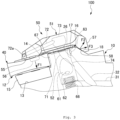
Fig. 1 is a side view showing a cutting tool according to an embodiment. -
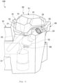
Fig. 2 is a perspective view showing a leading end of the cutting tool according to the present embodiment. -
Fig. 3 is a schematic side view showing a clamping location of the cutting insert. -
Fig. 4 is a schematic perspective showing the clamping location of the cutting insert as viewed from the rear side thereof. -
Fig. 5 is a perspective view showing a leading end of the tool body in a state in which a cutting insert is disposed on an insert mounting part. -
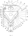
Fig. 6 is a plan view showing the leading end of the tool body in a state in which the cutting insert is disposed on the insert mounting part. -
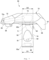
Fig. 7 is a side view of a fixing member. -
Fig. 8 is a perspective view of the fixing member. -
Fig. 9 is a front view of the fixing member. -
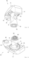
Fig. 10 is a perspective view of the fixing member as viewed from the rear and lower side thereof. -
Fig. 11 is a perspective view showing the fixing member with a coil spring mounted on a leading end of a fitting protrusion, as viewed from the back surface side of the fixing member. -
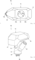
Fig. 12 is a plan view of the fixing member, which illustrates the shape of the fitting protrusion of the fixing member. -
Fig. 13 is a perspective view of the fixing member, which illustrates an engagement state of a fastening screw with an engagement recess formed in the fitting protrusion of the fixing member. -
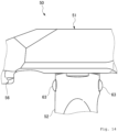
Fig. 14 is a side view showing a part of the fixing member having a guiding projection on a front part of the fitting protrusion. - Embodiments of the present invention will be discussed in detail below, with reference to the attached drawings.
- As shown in
Figs. 1-4 , acutting tool 100 according to the present embodiment includes atool body 10 and acutting insert 40, and thetool body 10 includes afixing member 50 and afastening screw 23. In thiscutting tool 100, thecutting insert 40 is mounted on a leading end of thetool body 10, and thecutting tool 100 is a turning tool that cuts the outer diameter or inner diameter of a rotating workpiece by using thecutting insert 40 provided on the leading end of thetool body 10. Thecutting insert 40 is pressed and fixed by thefixing member 50 of thetool body 10. - The
tool body 10 is formed in a quadrangular prism shape, and thecutting insert 40 is mounted on a leading end of thetool body 10. Thetool body 10 has, on the leading end thereof, aninsert mounting part 12, and thecutting insert 40 is mounting on theinsert mounting part 12.Such tool body 10 is formed of, for example, a metal material such as steel. The material of thetool body 10 may preferably be, for example, alloy tool steel (SKS5), die steel (SKD61) or maraging steel, which is elastic and resistant to plastic deformation. It should be noted that the shape of thetool body 10 is not limited to the quadrangular prism shape. - The
insert mounting part 12 has amounting surface 13 and aside wall surface 14 that is provided substantially perpendicularly on the rear side of themounting surface 13. Thecutting insert 40 is disposed on themounting surface 13 of theinsert mounting part 12 via ashim 15. It should be noted that thecutting insert 40 may be disposed on themounting surface 13 without providing theshim 15 therebetween. - The
tool body 10 has a fixingmember mounting part 16 on the rear side of theinsert mounting part 12, and thefixing member 50 is mounted on the fixingmember mounting part 16. The fixingmember mounting part 16 has amounting surface 17 which is a flat surface formed continuously to theside wall surface 14 of theinsert mounting part 12. In addition, the fixingmember mounting part 16 also has a slidingsurface 18 on the rear side of themounting surface 17. The slidingsurface 18 is an inclined surface which is gradually inclined downward from themounting surface 17 side toward the rear side. - As shown in
Figs. 5 and6 , the fixingmember mounting part 16 has afitting hole 21 and an internal thread (hole part) 22. Thefitting hole 21 is formed so as to be perpendicular to themounting surface 17. Theinternal thread 22 opens on a lateral side of thefitting hole 21 and is formed obliquely toward thefitting hole 21. Theinternal thread 22 communicates with an inner peripheral surface of thefitting hole 21. The fastening screw (pressing member) 23 is screwed into theinternal thread 22 from above the fixingmember mounting part 16, and a leading end of thefastening screw 23 is protruded into thefitting hole 21. A hexagon socket set screw may be used as thefastening screw 23. Although this example illustrates a structure in which thefastening screw 23 is screwed into theinternal thread 22, a hole part that communicates with thefitting hole 21 may be provided in place of theinternal thread 22, and a pressing member, such as a pin, may be inserted into such hole part by manipulating a cam or a lever. - A
guide recess 25 is formed in the inner peripheral surface of thefitting hole 21. Theguide recess 25 is provided on the opposite side of theinsert mounting part 12 and formed in a concave shape. In addition, anoutlet port 26 is formed in the inner peripheral surface of thefitting hole 21. Theoutlet port 26 is also provided on the opposite side of theinsert mounting part 12 and provided on the lower side with respect to theguide recess 25. - As shown in
Fig. 1 , thetool body 10, which has on its leading end theinsert mounting part 12 and the fixingmember mounting part 16, has inside thereof a coolantmain flow path 31, coolantbranch flow paths discharge flow path 34. - The coolant
main flow path 31 is formed along the longitudinal direction of thetool body 10. The coolantmain flow path 31 has a plurality ofinlet ports inlet port 35 is formed in a rear end surface of thetool body 10, theinlet port 36 is formed in a bottom surface of thetool body 10 in the middle thereof in the longitudinal direction, and theinlet port 37 is formed in the bottom surface of thetool body 10 on the leading end side thereof. Coolant is supplied from one of theseinlet ports main flow path 31, and theinlet ports - The coolant
branch flow path 32 is formed in an upper part of the leading end side of thetool body 10, and one end of the coolantbranch flow path 32 communicates with the coolantmain flow path 31. The other end of the coolantbranch flow path 32 communicates with thefitting hole 21, with the opening portion thereof serving as theoutlet port 26. The coolant which has been supplied into the coolantmain flow path 31 is delivered into the coolantbranch flow path 32. The fluid to be supplied into the coolantmain flow path 31 is not limited to the coolant, and various types of lubricants and cooling agents may be used, or mist or air may alternatively be supplied. - The coolant
branch flow path 33 is formed in a lower part of the leading end side of thetool body 10, and one end of the coolantbranch flow path 33 communicates with the coolantmain flow path 31. The other end of the coolantbranch flow path 33 communicates with one end of each of the plurality of coolantdischarge flow paths 34. The other end of each of the coolantdischarge flow paths 34 opens near the leading end of thetool body 10, and such opening portion serves as adischarge port 34a. The coolant which has been supplied into the coolantmain flow path 31 is delivered into the coolantbranch flow path 33. The coolant which has been delivered into the coolantbranch flow path 33 passes through the coolantdischarge flow path 34 and is discharged from thedischarge port 34a to cool and lubricate a region around a flank of the cuttinginsert 40. - As shown in
Figs. 5 and6 , the cuttinginsert 40 that is mounted on theinsert mounting part 12 of thetool body 10 may be formed in, for example, a flattened, substantially triangular solid shape. The cuttinginsert 40 has front and back end surfaces 43, and eachend surface 43 has threecorner parts 41. The cuttinginsert 40 has a fixinghole 42 at the center thereof. - The cutting
insert 40 includes: substantially triangular end surfaces 43 that face each other; and three peripheral side surfaces 44 connecting these end surfaces 43. Insuch cutting insert 40, a portion near eachcorner part 41 in anedge 45 between eachend surface 43 and theperipheral side surface 44 serves as acutting edge 46. - The cutting
insert 40 is placed and fixed onto theinsert mounting part 12 of thetool body 10 with one of the end surfaces 43 facing upward and any one of the threecorner parts 41 facing the leading end side. By using the cuttinginsert 40 with any one of the threecorner parts 41 each having the cuttingedge 46 in eachend surface 43 facing toward the leading end side, it is possible to provide cutting at six locations in total. - As shown in
Figs. 7-11 , the fixingmember 50 has a fixingmember body 51 and afitting protrusion 52. Thefitting protrusion 52 extends downward from a bottom part of the fixingmember body 51. - In the fixing
member body 51, a portion on the leading end side with respect to thefitting protrusion 52 serves as apressing part 55, and suchpressing part 55 is provided with apressing protrusion 56 that protrudes downward. Thepressing protrusion 56 is intended to fix the cuttinginsert 40, and thepressing protrusion 56 may have any shape as long as it can press the inner peripheral surface of the fixinghole 42 of the cutting insert. The fixingmember body 51 has a slidingsurface 58 on therear end 57 side with respect to thefitting protrusion 52, the slidingsurface 58 being gradually inclined backward as it extends downward. - The
fitting protrusion 52 is formed in a columnar shape. Thefitting protrusion 52 has engagement recesses 61 in opposite side portions thereof. Eachengagement recess 61 is formed as a recess that is gradually inclined toward the center as it extends in the protruding direction of thefitting protrusion 52. A bottom part of theengagement recess 61 is provided with acontact projection 62 that is projected in a convex shape. Aconvex guide projection 63 is formed in a rear part of thefitting protrusion 52 in the vicinity of the base end thereof. Thefitting protrusion 52 further has anannular recess 65 in the leading end thereof, and acoil spring 66 is fitted and mounted in suchannular recess 65. Anannular O ring 67 is mounted on a base end portion of thefitting protrusion 52. - As shown in
Fig. 12 , thefitting protrusion 52 has aleading end 52a which is formed in a circular shape with an outer diameter D1. On the other hand, abase end 52b of thefitting protrusion 52 is formed in an elliptical shape having a long diameter D1 and a short diameter D2, with the short diameter direction aligning with the front-back direction of the fixingmember 50. With such configuration, thefitting protrusion 52 is formed such that its dimension in the front-back direction gradually decreases from theleading end 52a toward thebase end 52b. - The fixing
member 50 has a coolantintroduction flow path 71, a coolantdischarge flow path 72, and acoolant reservoir 73. The coolantintroduction flow path 71 has one end thereof opening at a rear portion of thefitting protrusion 52 on the leading end side with respect to theguide projection 63, with the opening portion serving as aninlet port 74. Such coolantintroduction flow path 71 is formed so as to be curved while extending upward through thefitting protrusion 52 from theinlet port 74 toward the fixingmember body 51. In this example, two coolantdischarge flow paths 72 are formed. These coolantdischarge flow paths 72 may be, for example, formed along the front-back direction so as to be arranged in parallel at the leading end of the fixingmember body 51 and open at the leading end of the fixingmember body 51. The opening portions of the respective coolantdischarge flow paths 72 serve asdischarge ports 72a. Thecoolant reservoir 73 is formed in the fixingmember body 51 at a position above thefitting protrusion 52. Thecoolant reservoir 73 communicates with each of the coolantintroduction flow path 71 and the coolantdischarge flow path 72. Thecoolant reservoir 73 has a flow path whose cross-sectional area is larger than those of the coolantintroduction flow path 71 and the coolantdischarge flow path 72. It should be noted that the two coolantdischarge flow paths 72 may not necessarily be arranged in parallel to each other. - The following description will now describe a case where the cutting
insert 40 arranged on theinsert mounting part 12 of thetool body 10 is fixed by the fixingmember 50. - First, with respect to the
tool body 10 in which the cuttinginsert 40 is disposed on theinsert mounting part 12, thefitting protrusion 52 of the fixingmember 50 is inserted in thefitting hole 21 of the fixingmember mounting part 16, thereby allowing the fixingmember body 51 to be positioned above the fixingmember mounting part 16. Thepressing protrusion 56 formed on the pressingmember 55 of the fixingmember body 51 is fitted into the fixinghole 42 of the cuttinginsert 40. At this time, thecoil spring 66 on the leading end of thefitting protrusion 52 abuts against abottom part 21 a of thefitting hole 21. - In such state, the
fastening screw 23 is screwed into theinternal thread 22 of the fixingmember mounting part 16 of thetool body 10. As a result, as shown inFig. 13 , the leading end of thefastening screw 23 is protruded into thefitting hole 21 and inserted into one of the engagement recesses 61 formed in thefitting protrusion 52 and abuts against thecontact projection 62 formed on the bottom part of theengagement recess 61. By further screwingsuch fastening screw 23, thefitting protrusion 52 is drawn into thefitting hole 21 against the biasing force of thecoil spring 66 due to the fastening force of thefastening screw 23. As a result, the fixingmember 50 is pressed against the fixingmember mounting part 16 of thetool body 10. The cuttinginsert 40 is consequently pressed by thepressing part 55 of the fixingmember 50 against theshim 15 of theinsert mounting part 12 of thetool body 10 with a pressing force F1. - When the fixing
member 50 is pressed against the fixingmember mounting part 16, the slidingsurface 58 of the fixingmember body 51 slides in contact with the slidingsurface 18 of thetool body 10. As a result, the fixingmember 50 is attracted toward the rear side of thetool body 10 by a component force F3 of a reaction force F2 from the slidingsurface 18 of thetool body 10. With such configuration, the pressingprotrusion 56 that is being fitted in the fixinghole 42 of the cuttinginsert 40 is moved backward while abutting against the inner peripheral surface of thefitting hole 42. Accordingly, the cuttinginsert 40 is attracted toward the rear side of theinsert mounting part 12 of thetool body 10 by the pressingprotrusion 56 of the fixingmember 50 and pressed against theside wall surface 14. In this way, thecutting tool 100 has a double clamp fixing system in which two locations of the cutting insert 40 (i.e., theupper end surface 43 of the cuttinginsert 40 and the inner peripheral surface of the fixing hole 42) are pressed by the fixingmember 50. - Here, the
fitting protrusion 52 of the fixingmember 50 is formed such that the dimension of theelliptical base end 52b in the front-back direction is smaller than that of theleading end 52a. Thus, a gap is formed between thefitting protrusion 52 and thefitting hole 21 in the front-back direction of the fixingmember 50, such that the size of the gap gradually increases toward thebase end 52b of thefitting protrusion 52. With such configuration, when thefitting protrusion 52 is drawn into thefitting hole 21 by thefastening screw 23, the fixingmember 50 is smoothly displaced toward the rear side of thetool body 10. Thefitting protrusion 52 may be formed, throughout its length, in an elliptical shape whose short diameter direction aligns with the front-back direction of the fixingmember 50. In such case, by forming thefitting protrusion 52 such that the short diameter of thebase end 52b side is smaller than the short diameter of theleading end 52a side, it is possible to form a gap between thefitting protrusion 52 and thefitting hole 21 in the front-back direction of the fixingmember 50, such that the size of the gap gradually increases toward thebase end 52b of thefitting protrusion 52, and it is therefore possible to smoothly displace the fixingmember 50 that is being fitted in thefitting hole 21 toward the rear side of thetool body 10. - In the clamped state where the cutting
insert 40 is fixed onto theinsert mounting part 12, theguide projection 63 formed on thefitting protrusion 52 of the fixingmember 50 is fitted in theguide recess 25 formed in thefitting hole 21 of thetool body 10. As a result, the fixingmember 50 is prevented from being rotated around the axis of the fixingprotrusion 52 of the fixingmember 50, due to theguide projection 63 and theguide recess 25 that are being fitted with each other. Accordingly, the movement of the fixingmember 50 is restricted during the cutting process by the cuttinginsert 40 of thecutting tool 100, which allows the cuttinginsert 40 to perform a preferable cutting process. - As shown in
Fig. 14 , thefitting protrusion 52 of the fixingmember 50 may also be provided with aguide projection 63 on a front part of thefitting protrusion 52. In such case, aguide recess 25 that can be fitted with theguide projection 63 provided on the front part of thefitting protrusion 52 is provided on theinsert mounting part 12 side in thefitting hole 21. With such configuration, it is possible to further enhance the effect of preventing the fixingmember 50 from rotating around the axis of thefitting protrusion 52. - In the clamped state where the cutting
insert 40 is fixed onto theinsert mounting part 12, theO ring 67 mounted on the base end of thefitting protrusion 52 of the fixingmember 50 is attached tightly to the mountingsurface 17 of the fixingmember mounting part 16 of thetool body 10. Such configuration provides a sealing between the bottom part of the fixingmember 50 and the mountingsurface 17 of the fixingmember mounting part 16. - In addition, in the clamped state where the cutting
insert 40 is fixed onto theinsert mounting part 12, theinlet port 74 of the coolantintroduction flow path 71 formed in thefitting protrusion 52 of the fixingmember 50 communicates with theoutlet port 26 of the coolantbranch flow path 32 formed in thefitting hole 21 of thetool body 10. With such configuration, coolant that is delivered from the coolantmain flow path 31 into the coolantbranch flow path 33 is delivered into the coolantintroduction flow path 71 of the fixingmember 51. The coolant which has been delivered into the coolantintroduction flow path 71 is then delivered into the coolantdischarge flow path 72 via thecoolant reservoir 73 and discharged from thedischarge port 72a at the leading end of the fixingmember 50. As a result, the coolant discharged from thedischarge port 72a at the leading end of the fixingmember 50 is sprayed onto a cutting location by the cuttinginsert 40, together with the coolant discharged from thedischarge port 34a at the leading end of thetool body 10. With such configuration, the cutting location that is cut by the cuttinginsert 40 can be appropriately cooled and lubricated. Here, thecoolant reservoir 73 having a flow path with a large cross-sectional area is provided between the coolantintroduction flow path 71 and the coolantdischarge flow path 72. Accordingly, it is possible to prevent a pressure loss of the coolant in the process of being delivered from the coolantintroduction flow path 71 into the coolantdischarge flow path 72 having a small inner diameter, and to thereby appropriately discharge the coolant from thedischarge port 72a. - The following description will now describe a case of the removal of the cutting
insert 40 which has been fixed onto theinsert mounting part 12 of thetool body 10 by the fixingmember 50. - First, in order to remove the cutting
insert 40, thefastening screw 23 that fixes the fixingmember 50 is loosened. Then, thefastening screw 23 is pulled out from theengagement recess 61 of the fixingmember 50. As a result, the fixingmember 50 is pushed up in a direction away from the fixingmember mounting part 16 of thetool body 10 due to the resilient force of thecoil spring 66 provided on the leading end of thefitting protrusion 52. As a result, the fixation of the cuttinginsert 40 by the fixingmember 50 is released. In this way, when the fixingmember 50 is pushed up by thecoil spring 66, theguide projection 63 of thefitting protrusion 52 which has been fitted in theguide recess 25 in thefitting hole 21 is slid along theguide recess 25. As a result, the rear portion of the fixingmember 50 is guided along the contact surface between theguide projection 63 and theguide recess 25, whereby the rear portion of the fixingmember 50 is smoothly pushed up. Accordingly, the fixingmember 50 whose rear portion has been pushed up from the fixingmember mounting part 16 of thetool body 10 can easily be grasped and removed. - As explained above, the fixing
member 50 according to the present embodiment does not require a through hole for a screw to pass therethrough or a large surface to be engaged with a head part of the screw, and it is therefore possible to reduce the size of such fixingmember 50. With such configuration, it is possible to, for example, alleviate a cause of interference with a workpiece, etc. during a cutting process, such as inner diameter cutting, and thereby broaden the region of application. In addition, it is also possible to increase a discharge space for chips and therefore reduce the frequency of sudden fracture caused by clogging of chips. - In addition, since the leading end surface of the
fastening screw 23 abuts against thecontact projection 62 having a convex shape, it is possible to transmit the fastening force of thefastening screw 23 to thefitting protrusion 52 without any bias and thereby draw thefitting protrusion 52 into thefitting hole 21. - Furthermore, since the engagement recesses 61 are formed at multiple locations (two locations on opposite sides in this example) in the circumferential direction of the
fitting protrusion 52, it is possible to use any of those engagement recesses 61 so as to fit the situation, and is therefore possible to achieve availability for both right- and left-hand applications. - According to the present invention, it is possible to provide a fixing member and a cutting tool that can achieve size reduction while securing sufficient strength and can further achieve fixation of a cutting insert with high strength.
Claims (5)
- A fixing member that presses and fixes a cutting insert disposed on an insert mounting part of a tool body, the fixing member comprising:a fixing member body that has a pressing part for pressing the cutting insert;a fitting protrusion that is provided so as to protrude from a bottom part of the fixing member body, the fitting protrusion being fitted in a fitting hole formed in the tool body; andan engagement recess formed in a peripheral surface of the fitting protrusion, the engagement recess being engaged with a leading end of a pressing member which is inserted into a hole part that communicates with the fitting hole of the tool body,wherein the fitting protrusion is drawn into the fitting hole by the pressing member that engages with the engagement recess, whereby the pressing part presses and fixes the cutting insert.
- The fixing member according to claim 1, wherein the engagement recess is provided with a contact projection having a convex shape on a bottom part against which a leading end surface of the pressing member abuts.
- The fixing member according to claim 1 or 2, wherein the engagement recess is formed at multiple locations in a circumferential direction of the fitting protrusion.
- The fixing member according to any one of claims 1 to 3, wherein the hole part is an internal thread, and a fastening screw is screwed as the pressing member into the internal thread.
- A cutting tool, comprisingthe fixing member according to any one of claims 1 to 4;a tool body having an insert mounting part on which a cutting insert is disposed and a fixing member mounting part with which the fixing member is assembled; andthe cutting insert that is disposed on the insert mounting part and is pressed and fixed by the fixing member,wherein the fixing member mounting part includes:a fitting hole in which a fitting protrusion of the fixing member is fitted;a hole part that communicates with an inner peripheral surface of the fitting hole; anda pressing member that is inserted into the hole part, so that a leading end thereof is engaged with the engagement recess of the fixing member.
Applications Claiming Priority (1)
| Application Number | Priority Date | Filing Date | Title |
|---|---|---|---|
| JP2023174490A JP7445230B1 (en) | 2023-10-06 | 2023-10-06 | Fixed parts and cutting tools |
Publications (1)
| Publication Number | Publication Date |
|---|---|
| EP4534224A1 true EP4534224A1 (en) | 2025-04-09 |
Family
ID=90096772
Family Applications (1)
| Application Number | Title | Priority Date | Filing Date |
|---|---|---|---|
| EP24195767.9A Pending EP4534224A1 (en) | 2023-10-06 | 2024-08-22 | Fixing member and cutting tool |
Country Status (4)
| Country | Link |
|---|---|
| US (1) | US20250114843A1 (en) |
| EP (1) | EP4534224A1 (en) |
| JP (1) | JP7445230B1 (en) |
| CN (1) | CN119772219A (en) |
Citations (5)
| Publication number | Priority date | Publication date | Assignee | Title |
|---|---|---|---|---|
| DE2720249A1 (en) * | 1977-05-05 | 1978-11-16 | Pietro Guglielmetti | Fixing for hard metal cutting insert - has L=shaped clamp with oblique recess for transverse pin to act as wedge |
| SU948546A2 (en) * | 1981-02-25 | 1982-08-07 | Тюменский индустриальный институт им.Ленинского комсомола | Built-up cutting tool |
| US20110211923A1 (en) * | 2010-03-01 | 2011-09-01 | Iscar, Ltd. | Cutting Tool Assembly Having a Clamping Mechanism |
| WO2018034339A1 (en) | 2016-08-19 | 2018-02-22 | 京セラ株式会社 | Cutting tool and method for manufacturing cut product using same |
| US20230082274A1 (en) * | 2020-02-20 | 2023-03-16 | Walter Ag | Turning tool |
Family Cites Families (5)
| Publication number | Priority date | Publication date | Assignee | Title |
|---|---|---|---|---|
| JPS62259701A (en) * | 1986-05-02 | 1987-11-12 | ジ−テイ−イ−・ヴアレロン・コ−ポレ−シヨン | Pin lock insert holder |
| IL124282A (en) | 1998-04-29 | 2001-10-31 | Iscar Ltd | Cutting tool assembly and a cutting insert for use therein |
| JP2001062607A (en) | 1999-08-23 | 2001-03-13 | Mitsubishi Materials Corp | Clamp mechanism for indexable inserts |
| KR20140020192A (en) | 2012-08-08 | 2014-02-18 | 대구텍 유한회사 | Cutting tool assembly |
| US9211590B2 (en) | 2013-09-20 | 2015-12-15 | Kennametal Inc. | Screw head wedge clamp assembly for cutting tool |
-
2023
- 2023-10-06 JP JP2023174490A patent/JP7445230B1/en active Active
-
2024
- 2024-08-07 CN CN202411079390.6A patent/CN119772219A/en active Pending
- 2024-08-22 EP EP24195767.9A patent/EP4534224A1/en active Pending
- 2024-08-26 US US18/815,213 patent/US20250114843A1/en active Pending
Patent Citations (5)
| Publication number | Priority date | Publication date | Assignee | Title |
|---|---|---|---|---|
| DE2720249A1 (en) * | 1977-05-05 | 1978-11-16 | Pietro Guglielmetti | Fixing for hard metal cutting insert - has L=shaped clamp with oblique recess for transverse pin to act as wedge |
| SU948546A2 (en) * | 1981-02-25 | 1982-08-07 | Тюменский индустриальный институт им.Ленинского комсомола | Built-up cutting tool |
| US20110211923A1 (en) * | 2010-03-01 | 2011-09-01 | Iscar, Ltd. | Cutting Tool Assembly Having a Clamping Mechanism |
| WO2018034339A1 (en) | 2016-08-19 | 2018-02-22 | 京セラ株式会社 | Cutting tool and method for manufacturing cut product using same |
| US20230082274A1 (en) * | 2020-02-20 | 2023-03-16 | Walter Ag | Turning tool |
Also Published As
| Publication number | Publication date |
|---|---|
| JP2025064601A (en) | 2025-04-17 |
| CN119772219A (en) | 2025-04-08 |
| JP7445230B1 (en) | 2024-03-07 |
| US20250114843A1 (en) | 2025-04-10 |
Similar Documents
| Publication | Publication Date | Title |
|---|---|---|
| EP4549062A1 (en) | Fixing member and cutting tool | |
| CN107708900B (en) | Cutting tool with nozzle with internal coolant channel | |
| US8137034B2 (en) | Tool system | |
| US8057130B2 (en) | Metal cutting system for effective coolant delivery | |
| SK127496A3 (en) | Cutting tool | |
| WO2010096014A1 (en) | Cutting tool and cutting insert with fluid flow structures | |
| RU2739744C1 (en) | Grooving tool | |
| WO2010050227A1 (en) | Tool for cutting hole inner surface and method of cutting hole inner surface | |
| KR102560935B1 (en) | turning tool holder | |
| EP4534224A1 (en) | Fixing member and cutting tool | |
| EP2208563A1 (en) | Head member and tool main body of detachable insert cutting tool, and detachable insert cutting tool | |
| US11679513B2 (en) | End effector exchange device | |
| JP2006055916A (en) | Throw away type bite | |
| US10486238B2 (en) | Cutting tool | |
| JP7498901B1 (en) | Fixing members and cutting tools | |
| US8066455B2 (en) | Connection system for two tool parts | |
| JP7420311B1 (en) | Fixed parts and cutting tools | |
| US20060159527A1 (en) | Clamping mechanism for cutting insert, and cutting insert | |
| JP7459451B1 (en) | Fixing member, tool body and cutting tool | |
| KR20250093491A (en) | Cutting tool assembly | |
| JP2019171508A (en) | Clamp mechanism of cutting insert and cutting insert | |
| EP4599964A1 (en) | Cutting tool body and cutting tool | |
| KR20130123312A (en) | Cutting tool assembly | |
| JP2021065948A (en) | Cutting tool |
Legal Events
| Date | Code | Title | Description |
|---|---|---|---|
| PUAI | Public reference made under article 153(3) epc to a published international application that has entered the european phase |
Free format text: ORIGINAL CODE: 0009012 |
|
| STAA | Information on the status of an ep patent application or granted ep patent |
Free format text: STATUS: REQUEST FOR EXAMINATION WAS MADE |
|
| 17P | Request for examination filed |
Effective date: 20240920 |
|
| AK | Designated contracting states |
Kind code of ref document: A1 Designated state(s): AL AT BE BG CH CY CZ DE DK EE ES FI FR GB GR HR HU IE IS IT LI LT LU LV MC ME MK MT NL NO PL PT RO RS SE SI SK SM TR |