EP4534223A1 - Sintered body and cutting tool - Google Patents
Sintered body and cutting tool Download PDFInfo
- Publication number
- EP4534223A1 EP4534223A1 EP22943727.2A EP22943727A EP4534223A1 EP 4534223 A1 EP4534223 A1 EP 4534223A1 EP 22943727 A EP22943727 A EP 22943727A EP 4534223 A1 EP4534223 A1 EP 4534223A1
- Authority
- EP
- European Patent Office
- Prior art keywords
- sintered material
- binder
- sample
- diamond particles
- mass
- Prior art date
- Legal status (The legal status is an assumption and is not a legal conclusion. Google has not performed a legal analysis and makes no representation as to the accuracy of the status listed.)
- Pending
Links
Images

Classifications
-
- C—CHEMISTRY; METALLURGY
- C22—METALLURGY; FERROUS OR NON-FERROUS ALLOYS; TREATMENT OF ALLOYS OR NON-FERROUS METALS
- C22C—ALLOYS
- C22C26/00—Alloys containing diamond or cubic or wurtzitic boron nitride, fullerenes or carbon nanotubes
-
- B—PERFORMING OPERATIONS; TRANSPORTING
- B23—MACHINE TOOLS; METAL-WORKING NOT OTHERWISE PROVIDED FOR
- B23B—TURNING; BORING
- B23B27/00—Tools for turning or boring machines; Tools of a similar kind in general; Accessories therefor
- B23B27/14—Cutting tools of which the bits or tips or cutting inserts are of special material
- B23B27/18—Cutting tools of which the bits or tips or cutting inserts are of special material with cutting bits or tips or cutting inserts rigidly mounted, e.g. by brazing
- B23B27/20—Cutting tools of which the bits or tips or cutting inserts are of special material with cutting bits or tips or cutting inserts rigidly mounted, e.g. by brazing with diamond bits or cutting inserts
-
- C—CHEMISTRY; METALLURGY
- C04—CEMENTS; CONCRETE; ARTIFICIAL STONE; CERAMICS; REFRACTORIES
- C04B—LIME, MAGNESIA; SLAG; CEMENTS; COMPOSITIONS THEREOF, e.g. MORTARS, CONCRETE OR LIKE BUILDING MATERIALS; ARTIFICIAL STONE; CERAMICS; REFRACTORIES; TREATMENT OF NATURAL STONE
- C04B35/00—Shaped ceramic products characterised by their composition; Ceramics compositions; Processing powders of inorganic compounds preparatory to the manufacturing of ceramic products
- C04B35/515—Shaped ceramic products characterised by their composition; Ceramics compositions; Processing powders of inorganic compounds preparatory to the manufacturing of ceramic products based on non-oxide ceramics
- C04B35/52—Shaped ceramic products characterised by their composition; Ceramics compositions; Processing powders of inorganic compounds preparatory to the manufacturing of ceramic products based on non-oxide ceramics based on carbon, e.g. graphite
-
- B—PERFORMING OPERATIONS; TRANSPORTING
- B22—CASTING; POWDER METALLURGY
- B22F—WORKING METALLIC POWDER; MANUFACTURE OF ARTICLES FROM METALLIC POWDER; MAKING METALLIC POWDER; APPARATUS OR DEVICES SPECIALLY ADAPTED FOR METALLIC POWDER
- B22F3/00—Manufacture of workpieces or articles from metallic powder characterised by the manner of compacting or sintering; Apparatus specially adapted therefor ; Presses and furnaces
- B22F3/12—Both compacting and sintering
- B22F3/14—Both compacting and sintering simultaneously
-
- B—PERFORMING OPERATIONS; TRANSPORTING
- B22—CASTING; POWDER METALLURGY
- B22F—WORKING METALLIC POWDER; MANUFACTURE OF ARTICLES FROM METALLIC POWDER; MAKING METALLIC POWDER; APPARATUS OR DEVICES SPECIALLY ADAPTED FOR METALLIC POWDER
- B22F7/00—Manufacture of composite layers, workpieces, or articles, comprising metallic powder, by sintering the powder, with or without compacting wherein at least one part is obtained by sintering or compression
- B22F7/06—Manufacture of composite layers, workpieces, or articles, comprising metallic powder, by sintering the powder, with or without compacting wherein at least one part is obtained by sintering or compression of composite workpieces or articles from parts, e.g. to form tipped tools
- B22F7/08—Manufacture of composite layers, workpieces, or articles, comprising metallic powder, by sintering the powder, with or without compacting wherein at least one part is obtained by sintering or compression of composite workpieces or articles from parts, e.g. to form tipped tools with one or more parts not made from powder
-
- B—PERFORMING OPERATIONS; TRANSPORTING
- B23—MACHINE TOOLS; METAL-WORKING NOT OTHERWISE PROVIDED FOR
- B23B—TURNING; BORING
- B23B27/00—Tools for turning or boring machines; Tools of a similar kind in general; Accessories therefor
- B23B27/14—Cutting tools of which the bits or tips or cutting inserts are of special material
-
- B—PERFORMING OPERATIONS; TRANSPORTING
- B24—GRINDING; POLISHING
- B24D—TOOLS FOR GRINDING, BUFFING OR SHARPENING
- B24D18/00—Manufacture of grinding tools or other grinding devices, e.g. wheels, not otherwise provided for
- B24D18/0072—Manufacture of grinding tools or other grinding devices, e.g. wheels, not otherwise provided for using adhesives for bonding abrasive particles or grinding elements to a support, e.g. by gluing
-
- C—CHEMISTRY; METALLURGY
- C04—CEMENTS; CONCRETE; ARTIFICIAL STONE; CERAMICS; REFRACTORIES
- C04B—LIME, MAGNESIA; SLAG; CEMENTS; COMPOSITIONS THEREOF, e.g. MORTARS, CONCRETE OR LIKE BUILDING MATERIALS; ARTIFICIAL STONE; CERAMICS; REFRACTORIES; TREATMENT OF NATURAL STONE
- C04B35/00—Shaped ceramic products characterised by their composition; Ceramics compositions; Processing powders of inorganic compounds preparatory to the manufacturing of ceramic products
- C04B35/515—Shaped ceramic products characterised by their composition; Ceramics compositions; Processing powders of inorganic compounds preparatory to the manufacturing of ceramic products based on non-oxide ceramics
- C04B35/52—Shaped ceramic products characterised by their composition; Ceramics compositions; Processing powders of inorganic compounds preparatory to the manufacturing of ceramic products based on non-oxide ceramics based on carbon, e.g. graphite
- C04B35/528—Shaped ceramic products characterised by their composition; Ceramics compositions; Processing powders of inorganic compounds preparatory to the manufacturing of ceramic products based on non-oxide ceramics based on carbon, e.g. graphite obtained from carbonaceous particles with or without other non-organic components
-
- C—CHEMISTRY; METALLURGY
- C04—CEMENTS; CONCRETE; ARTIFICIAL STONE; CERAMICS; REFRACTORIES
- C04B—LIME, MAGNESIA; SLAG; CEMENTS; COMPOSITIONS THEREOF, e.g. MORTARS, CONCRETE OR LIKE BUILDING MATERIALS; ARTIFICIAL STONE; CERAMICS; REFRACTORIES; TREATMENT OF NATURAL STONE
- C04B35/00—Shaped ceramic products characterised by their composition; Ceramics compositions; Processing powders of inorganic compounds preparatory to the manufacturing of ceramic products
- C04B35/622—Forming processes; Processing powders of inorganic compounds preparatory to the manufacturing of ceramic products
- C04B35/626—Preparing or treating the powders individually or as batches ; preparing or treating macroscopic reinforcing agents for ceramic products, e.g. fibres; mechanical aspects section B
- C04B35/63—Preparing or treating the powders individually or as batches ; preparing or treating macroscopic reinforcing agents for ceramic products, e.g. fibres; mechanical aspects section B using additives specially adapted for forming the products, e.g.. binder binders
- C04B35/6303—Inorganic additives
-
- C—CHEMISTRY; METALLURGY
- C22—METALLURGY; FERROUS OR NON-FERROUS ALLOYS; TREATMENT OF ALLOYS OR NON-FERROUS METALS
- C22C—ALLOYS
- C22C1/00—Making non-ferrous alloys
- C22C1/04—Making non-ferrous alloys by powder metallurgy
- C22C1/05—Mixtures of metal powder with non-metallic powder
-
- B—PERFORMING OPERATIONS; TRANSPORTING
- B22—CASTING; POWDER METALLURGY
- B22F—WORKING METALLIC POWDER; MANUFACTURE OF ARTICLES FROM METALLIC POWDER; MAKING METALLIC POWDER; APPARATUS OR DEVICES SPECIALLY ADAPTED FOR METALLIC POWDER
- B22F5/00—Manufacture of workpieces or articles from metallic powder characterised by the special shape of the product
- B22F2005/001—Cutting tools, earth boring or grinding tool other than table ware
-
- C—CHEMISTRY; METALLURGY
- C04—CEMENTS; CONCRETE; ARTIFICIAL STONE; CERAMICS; REFRACTORIES
- C04B—LIME, MAGNESIA; SLAG; CEMENTS; COMPOSITIONS THEREOF, e.g. MORTARS, CONCRETE OR LIKE BUILDING MATERIALS; ARTIFICIAL STONE; CERAMICS; REFRACTORIES; TREATMENT OF NATURAL STONE
- C04B2235/00—Aspects relating to ceramic starting mixtures or sintered ceramic products
- C04B2235/02—Composition of constituents of the starting material or of secondary phases of the final product
- C04B2235/30—Constituents and secondary phases not being of a fibrous nature
- C04B2235/42—Non metallic elements added as constituents or additives, e.g. sulfur, phosphor, selenium or tellurium
- C04B2235/421—Boron
-
- C—CHEMISTRY; METALLURGY
- C04—CEMENTS; CONCRETE; ARTIFICIAL STONE; CERAMICS; REFRACTORIES
- C04B—LIME, MAGNESIA; SLAG; CEMENTS; COMPOSITIONS THEREOF, e.g. MORTARS, CONCRETE OR LIKE BUILDING MATERIALS; ARTIFICIAL STONE; CERAMICS; REFRACTORIES; TREATMENT OF NATURAL STONE
- C04B2235/00—Aspects relating to ceramic starting mixtures or sintered ceramic products
- C04B2235/02—Composition of constituents of the starting material or of secondary phases of the final product
- C04B2235/30—Constituents and secondary phases not being of a fibrous nature
- C04B2235/42—Non metallic elements added as constituents or additives, e.g. sulfur, phosphor, selenium or tellurium
- C04B2235/422—Carbon
- C04B2235/427—Diamond
-
- C—CHEMISTRY; METALLURGY
- C04—CEMENTS; CONCRETE; ARTIFICIAL STONE; CERAMICS; REFRACTORIES
- C04B—LIME, MAGNESIA; SLAG; CEMENTS; COMPOSITIONS THEREOF, e.g. MORTARS, CONCRETE OR LIKE BUILDING MATERIALS; ARTIFICIAL STONE; CERAMICS; REFRACTORIES; TREATMENT OF NATURAL STONE
- C04B2235/00—Aspects relating to ceramic starting mixtures or sintered ceramic products
- C04B2235/02—Composition of constituents of the starting material or of secondary phases of the final product
- C04B2235/50—Constituents or additives of the starting mixture chosen for their shape or used because of their shape or their physical appearance
- C04B2235/54—Particle size related information
- C04B2235/5418—Particle size related information expressed by the size of the particles or aggregates thereof
- C04B2235/5436—Particle size related information expressed by the size of the particles or aggregates thereof micrometer sized, i.e. from 1 to 100 micron
-
- C—CHEMISTRY; METALLURGY
- C04—CEMENTS; CONCRETE; ARTIFICIAL STONE; CERAMICS; REFRACTORIES
- C04B—LIME, MAGNESIA; SLAG; CEMENTS; COMPOSITIONS THEREOF, e.g. MORTARS, CONCRETE OR LIKE BUILDING MATERIALS; ARTIFICIAL STONE; CERAMICS; REFRACTORIES; TREATMENT OF NATURAL STONE
- C04B2235/00—Aspects relating to ceramic starting mixtures or sintered ceramic products
- C04B2235/02—Composition of constituents of the starting material or of secondary phases of the final product
- C04B2235/50—Constituents or additives of the starting mixture chosen for their shape or used because of their shape or their physical appearance
- C04B2235/54—Particle size related information
- C04B2235/5418—Particle size related information expressed by the size of the particles or aggregates thereof
- C04B2235/5445—Particle size related information expressed by the size of the particles or aggregates thereof submicron sized, i.e. from 0,1 to 1 micron
-
- C—CHEMISTRY; METALLURGY
- C04—CEMENTS; CONCRETE; ARTIFICIAL STONE; CERAMICS; REFRACTORIES
- C04B—LIME, MAGNESIA; SLAG; CEMENTS; COMPOSITIONS THEREOF, e.g. MORTARS, CONCRETE OR LIKE BUILDING MATERIALS; ARTIFICIAL STONE; CERAMICS; REFRACTORIES; TREATMENT OF NATURAL STONE
- C04B2235/00—Aspects relating to ceramic starting mixtures or sintered ceramic products
- C04B2235/65—Aspects relating to heat treatments of ceramic bodies such as green ceramics or pre-sintered ceramics, e.g. burning, sintering or melting processes
- C04B2235/656—Aspects relating to heat treatments of ceramic bodies such as green ceramics or pre-sintered ceramics, e.g. burning, sintering or melting processes characterised by specific heating conditions during heat treatment
- C04B2235/6567—Treatment time
-
- C—CHEMISTRY; METALLURGY
- C04—CEMENTS; CONCRETE; ARTIFICIAL STONE; CERAMICS; REFRACTORIES
- C04B—LIME, MAGNESIA; SLAG; CEMENTS; COMPOSITIONS THEREOF, e.g. MORTARS, CONCRETE OR LIKE BUILDING MATERIALS; ARTIFICIAL STONE; CERAMICS; REFRACTORIES; TREATMENT OF NATURAL STONE
- C04B2235/00—Aspects relating to ceramic starting mixtures or sintered ceramic products
- C04B2235/70—Aspects relating to sintered or melt-casted ceramic products
- C04B2235/72—Products characterised by the absence or the low content of specific components, e.g. alkali metal free alumina ceramics
-
- C—CHEMISTRY; METALLURGY
- C04—CEMENTS; CONCRETE; ARTIFICIAL STONE; CERAMICS; REFRACTORIES
- C04B—LIME, MAGNESIA; SLAG; CEMENTS; COMPOSITIONS THEREOF, e.g. MORTARS, CONCRETE OR LIKE BUILDING MATERIALS; ARTIFICIAL STONE; CERAMICS; REFRACTORIES; TREATMENT OF NATURAL STONE
- C04B2235/00—Aspects relating to ceramic starting mixtures or sintered ceramic products
- C04B2235/70—Aspects relating to sintered or melt-casted ceramic products
- C04B2235/74—Physical characteristics
- C04B2235/78—Grain sizes and shapes, product microstructures, e.g. acicular grains, equiaxed grains, platelet-structures
- C04B2235/785—Submicron sized grains, i.e. from 0,1 to 1 micron
-
- C—CHEMISTRY; METALLURGY
- C04—CEMENTS; CONCRETE; ARTIFICIAL STONE; CERAMICS; REFRACTORIES
- C04B—LIME, MAGNESIA; SLAG; CEMENTS; COMPOSITIONS THEREOF, e.g. MORTARS, CONCRETE OR LIKE BUILDING MATERIALS; ARTIFICIAL STONE; CERAMICS; REFRACTORIES; TREATMENT OF NATURAL STONE
- C04B2235/00—Aspects relating to ceramic starting mixtures or sintered ceramic products
- C04B2235/70—Aspects relating to sintered or melt-casted ceramic products
- C04B2235/74—Physical characteristics
- C04B2235/78—Grain sizes and shapes, product microstructures, e.g. acicular grains, equiaxed grains, platelet-structures
- C04B2235/786—Micrometer sized grains, i.e. from 1 to 100 micron
-
- C—CHEMISTRY; METALLURGY
- C04—CEMENTS; CONCRETE; ARTIFICIAL STONE; CERAMICS; REFRACTORIES
- C04B—LIME, MAGNESIA; SLAG; CEMENTS; COMPOSITIONS THEREOF, e.g. MORTARS, CONCRETE OR LIKE BUILDING MATERIALS; ARTIFICIAL STONE; CERAMICS; REFRACTORIES; TREATMENT OF NATURAL STONE
- C04B2235/00—Aspects relating to ceramic starting mixtures or sintered ceramic products
- C04B2235/70—Aspects relating to sintered or melt-casted ceramic products
- C04B2235/80—Phases present in the sintered or melt-cast ceramic products other than the main phase
-
- C—CHEMISTRY; METALLURGY
- C04—CEMENTS; CONCRETE; ARTIFICIAL STONE; CERAMICS; REFRACTORIES
- C04B—LIME, MAGNESIA; SLAG; CEMENTS; COMPOSITIONS THEREOF, e.g. MORTARS, CONCRETE OR LIKE BUILDING MATERIALS; ARTIFICIAL STONE; CERAMICS; REFRACTORIES; TREATMENT OF NATURAL STONE
- C04B35/00—Shaped ceramic products characterised by their composition; Ceramics compositions; Processing powders of inorganic compounds preparatory to the manufacturing of ceramic products
- C04B35/622—Forming processes; Processing powders of inorganic compounds preparatory to the manufacturing of ceramic products
- C04B35/64—Burning or sintering processes
- C04B35/645—Pressure sintering
-
- C—CHEMISTRY; METALLURGY
- C22—METALLURGY; FERROUS OR NON-FERROUS ALLOYS; TREATMENT OF ALLOYS OR NON-FERROUS METALS
- C22C—ALLOYS
- C22C26/00—Alloys containing diamond or cubic or wurtzitic boron nitride, fullerenes or carbon nanotubes
- C22C2026/005—Alloys containing diamond or cubic or wurtzitic boron nitride, fullerenes or carbon nanotubes with additional metal compounds being borides
-
- C—CHEMISTRY; METALLURGY
- C22—METALLURGY; FERROUS OR NON-FERROUS ALLOYS; TREATMENT OF ALLOYS OR NON-FERROUS METALS
- C22C—ALLOYS
- C22C26/00—Alloys containing diamond or cubic or wurtzitic boron nitride, fullerenes or carbon nanotubes
- C22C2026/008—Alloys containing diamond or cubic or wurtzitic boron nitride, fullerenes or carbon nanotubes with additional metal compounds other than carbides, borides or nitrides
Definitions
- a sintered material of the present disclosure includes diamond particles and a binder.
- Each of the diamond particles has a boron concentration of 0.001 mass% to 0.1 mass%.
- the binder has a boron concentration of 0.01 mass% to 0.5 mass%.
- the sintered material of the present disclosure can improve tool life when applied to a cutting tool.
- the tool life can be improved.
- FIG. 1 is a plan view of cutting insert 100.
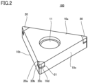
- FIG. 2 is a perspective view of cutting insert 100.
- cutting insert 100 includes a base member 10 and cutting parts 20.
- Cutting insert 100 has a polygonal shape (for example, a triangular shape) in a plan view.
- the polygonal shape (triangular shape) do not have to be a strict polygonal shape (triangular shape). More specifically, the corners of cutting insert 100 in a plan view may be rounded.
- Base member 10 has a polygonal shape (for example, a triangular shape) in a plan view.
- Base member 10 has a top surface 10a, a bottom surface 10b, and a side surface 10c.
- Top surface 10a and bottom surface 10b are end surfaces of base member 10 in a thickness direction.
- Bottom surface 10b is a surface opposite to top surface 10a of base member 10 in the thickness direction.
- Side surface 10c is a surface contiguous with top surface 10a and bottom surface 10b.
- a through-hole 11 is formed in base member 10.
- Through-hole 11 extends through base member 10 in the thickness direction.
- Through-hole 11 is formed at the center of base member 10 in a plan view.
- Cutting insert 100 is used for cutting, for example, by inserting a fixing member (not shown) into through-hole 11 and fastening the fixing member to a tool holder (not shown).
- through-hole 11 do not have to be formed in base member 10.
- Base member 10 is formed of, for example, cemented carbide.
- Cemented carbide is a composite material obtained by sintering carbide particles and a binder.
- the carbide particles are particles of, for example, tungsten carbide, titanium carbide, tantalum carbide, or the like.
- the binder is, for example, cobalt, nickel, iron, or the like.
- base member 10 may be formed of a material other than cemented carbide.
- the cross section of the cut sample is observed with a scanning electron microscope (SEM).
- SEM image a reflected electron image (hereinafter, referred to as "SEM image") of the cross section of the cut sample is obtained.
- the magnification is adjusted so that 100 or more diamond particles are included in the measurement field of view.
- the SEM images are acquired at five positions in the cross section of the cut sample.
- the ratio of diamond particles within the sintered material of cutting part 20 is calculated by the following method.
- a sample including a cross section is cut out from any position of cutting part 20.
- the sample is cut out by using, for example, a focused ion beam apparatus, a cross polisher apparatus, or the like.
- the cross section of the cut sample is observed with the SEM.
- an SEM image of the cross section of the cut sample is obtained.
- the magnification is adjusted so that 100 or more diamond particles are included in the measurement field of view.
- the SEM images are acquired at five positions in the cross section of the cut sample.
- the sintering pressure is, for example, 4.5 GPa or more and 6.5 GPa or more.
- the holding time is, for example, 40 minutes or more and less than 60 minutes.
- cutting part 20 When cutting part 20 is charged by contact between cutting part 20 and a workpiece, triboplasma is generated between cutting part 20 and the workpiece, and wear of cutting part 20 may easily progress.
- the sintered material of cutting part 20 has a resistivity of 3.0 ⁇ cm or less as measured after removing the binder, cutting part 20 is less likely to be charged by contact with the workpiece, and the progress of wear of cutting part 20 due to the generation of triboplasma can be suppressed.
- cutting inserts having cutting parts 20 formed using samples 3 to 24 were prepared.
- the cutting inserts had a shape corresponding to the cutting insert SNEW1204ADFR manufactured by Sumitomo Electric Hardmetal Corp.
- the cutting insert was attached to the holder RF4160R manufactured by Sumitomo Electric Hardmetal Corp., and subjected to a milling process.
- the milling process was performed with a feed of 0.2 mm/t and a depth of cut of 0.6 mm. This cutting was dry machining in which no coolant was supplied.
- the workpiece subjected to the cutting had dimensions of 90 mm ⁇ 90 mm ⁇ 90 mm, and the material of the workpiece subjected to the cutting was a glass-containing resin.
- the binder to have a boron concentration of 0.5 mass% or less, the value calculated by dividing the peak intensity of the compound in X-ray diffractometry by the peak intensity of diamond in X-ray diffractometry can be set to 0.15 or less, that is, the precipitation of the compound in the binder could be suppressed.
- the binder contained in the sintered material of cutting part 20 is cobalt, but the binder contained in the sintered material of cutting part 20 is not limited to cobalt.
Landscapes
- Chemical & Material Sciences (AREA)
- Engineering & Computer Science (AREA)
- Materials Engineering (AREA)
- Mechanical Engineering (AREA)
- Organic Chemistry (AREA)
- Manufacturing & Machinery (AREA)
- Ceramic Engineering (AREA)
- Metallurgy (AREA)
- Inorganic Chemistry (AREA)
- Structural Engineering (AREA)
- Composite Materials (AREA)
- Cutting Tools, Boring Holders, And Turrets (AREA)
- Powder Metallurgy (AREA)
Abstract
Description
- The present disclosure relates to a sintered material and a cutting tool.
- Patent literature 1 (
Japanese Unexamined Patent Application Publication No. 2008-133172 - Patent literature 2 (
Japanese Unexamined Patent Application Publication No. 58-199777 patent literature 2 is formed by mixing diamond powder and catalyst metal powder, and heating and pressurizing the mixture. The catalyst metal powder contains boron carbide-added powder and metal powder (iron, nickel, cobalt, etc.). -
- Patent literature 1:
Japanese Unexamined Patent Application Publication No. 2008-133172 - Patent literature 2:
Japanese Unexamined Patent Application Publication No. 58-199777 - A sintered material of the present disclosure includes diamond particles and a binder. Each of the diamond particles has a boron concentration of 0.001 mass% to 0.1 mass%. The binder has a boron concentration of 0.01 mass% to 0.5 mass%.
-
-
FIG. 1 is a plan view of acutting insert 100. -
FIG. 2 is a perspective view of cutting insert 100. -
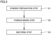
FIG. 3 is a manufacturing step chart showing a method of manufacturing a sintered material of acutting part 20. - As a result of intensive studies, the present inventors have found that there is room for improvement in tool life when the sintered material described in patent literature 1 and the sintered material described in
patent literature 2 are applied to a cutting tool. The present disclosure provides a sintered material which can improve tool life when applied to a cutting tool. - The sintered material of the present disclosure can improve tool life when applied to a cutting tool.
- First, embodiments of the present disclosure will be listed and described.
- (1) A sintered material according to an embodiment includes diamond particles and a binder. Each of the diamond particles has a boron concentration of 0.001 mass% to 0.1 mass%. The binder has a boron concentration of 0.01 mass% to 0.5 mass%.
According to the sintered material of the above (1), when the sintered material is applied to a cutting tool, the tool life can be improved. - (2) In the sintered material according to the above (1), the binder may have a boron concentration of 0.05 mass% to 0.5 mass%.
- (3) The sintered material according to the above (1) or (2) may further include a compound precipitated within the binder. The compound may contain at least two or more among cobalt, boron, and carbon. A value calculated by dividing a peak intensity of the compound in X-ray diffractometry by a peak intensity of diamond in X-ray diffractometry may be 0.15 or less.
- (4) In the sintered material according to the above (3), the compound may be at least one of Co2 2 B4 C2, W2 Co2 1 B6, W2 Co2 B6, or CoWB.
- (5) In the sintered material according to the above (3) or (4), the value calculated by dividing the peak intensity of the compound in X-ray diffractometry by the peak intensity of diamond in X-ray diffractometry may be 0.01 to 0.15.
- (6) In the sintered material according to any one of the above (1) to (5), a resistivity of the sintered material may be 3.0 Ω·cm or less as measured with the binder being removed.
According to the sintered material of the above (6), when the sintered material is applied to a cutting tool, generation of triboplasma can be suppressed. - (7) In the sintered material according to any one of the above (1) to (6), the diamond particles may have an average particle size of 0.5 µm to 50 µm. A ratio of the diamond particles within the sintered material may be 80 vol% to 99 vol%.
- (8) In the sintered material according to any one of the above (1) to (7), the binder may contain at least one selected from the group consisting of an elemental metal, an alloy, and an intermetallic compound. The elemental metal, the alloy, and the intermetallic compound may contain at least one metallic element selected from the group consisting of group 4 elements in the periodic table, group 5 elements in the periodic table, group 6 elements in the periodic table, iron, aluminum, silicon, cobalt, and nickel.
- (9) In the sintered material according to any one of the above (1) to (8), the binder at least may contain cobalt.
- (10) A cutting tool according to an embodiment includes a cutting part. The cutting part is formed of the sintered material according to any one of the above (1) to (9).
- According to the cutting tool of the above (10), the tool life can be improved.
- The details of embodiments of the present disclosure will be described with reference to the drawings. In the drawings, the same or corresponding parts are denoted by the same reference numerals, and the description thereof will not be repeated.
- A cutting tool according to the embodiment is, for example, a
cutting insert 100. The cutting tool according to the embodiment is not limited to cuttinginsert 100, but cuttinginsert 100 will be described below as an example of the cutting tool according to the embodiment. Other examples of the cutting tool according to the embodiment include a drill, an end mill, and a wear resistant tool. - A configuration of
cutting insert 100 will be described. -
FIG. 1 is a plan view of cutting insert 100.FIG. 2 is a perspective view of cutting insert 100. As shown inFIGs. 1 and2 , cuttinginsert 100 includes abase member 10 and cuttingparts 20.Cutting insert 100 has a polygonal shape (for example, a triangular shape) in a plan view. The polygonal shape (triangular shape) do not have to be a strict polygonal shape (triangular shape). More specifically, the corners of cutting insert 100 in a plan view may be rounded. -
Base member 10 has a polygonal shape (for example, a triangular shape) in a plan view.Base member 10 has atop surface 10a, abottom surface 10b, and aside surface 10c.Top surface 10a andbottom surface 10b are end surfaces ofbase member 10 in a thickness direction.Bottom surface 10b is a surface opposite totop surface 10a ofbase member 10 in the thickness direction.Side surface 10c is a surface contiguous withtop surface 10a andbottom surface 10b. -
Top surface 10a hasattachment portions 10d.Attachment portions 10d are located at corners oftop surface 10a in a plan view. A distance betweentop surface 10a andbottom surface 10b inattachment portion 10d is smaller than a distance betweentop surface 10a andbottom surface 10b in the portion other thanattachment portion 10d. That is, there is a step betweenattachment portion 10d and the portion oftop surface 10a other thanattachment portion 10d. - A through-
hole 11 is formed inbase member 10. Through-hole 11 extends throughbase member 10 in the thickness direction. Through-hole 11 is formed at the center ofbase member 10 in a plan view. Cuttinginsert 100 is used for cutting, for example, by inserting a fixing member (not shown) into through-hole 11 and fastening the fixing member to a tool holder (not shown). However, through-hole 11 do not have to be formed inbase member 10. -
Base member 10 is formed of, for example, cemented carbide. Cemented carbide is a composite material obtained by sintering carbide particles and a binder. The carbide particles are particles of, for example, tungsten carbide, titanium carbide, tantalum carbide, or the like. The binder is, for example, cobalt, nickel, iron, or the like. However,base member 10 may be formed of a material other than cemented carbide. - Cutting
part 20 is attached toattachment portion 10d. Cuttingpart 20 is attached tobase member 10 by brazing, for example. Cuttingpart 20 includes arake face 20a, aflank face 20b, and acutting edge 20c.Rake face 20a is contiguous with the portion oftop surface 10a other thanattachment portion 10d.Flank face 20b is contiguous withside surface 10c. Cuttingedge 20c is formed on a ridge line betweenrake face 20a andflank face 20b. Aback metal 21 may be disposed on a bottom surface (a surface opposite to rakeface 20a) of cuttingpart 20. Backmetal 21 is formed of, for example, cemented carbide. - Cutting
part 20 is formed of a sintered material containing diamond particles and a binder. The diamond particles within the sintered material of cuttingpart 20 preferably have an average particle size of 0.5 µm to 50 µm. A ratio (volume ratio) of the diamond particles within the sintered material of cuttingpart 20 is preferably 80 vol% to 99 vol%. The binder contains, for example, cobalt. The binder may contain tungsten or titanium in addition to cobalt. The component having the highest content in the binder is preferably cobalt. - The average particle size of the diamond particles within the sintered material of cutting
part 20 is calculated by the following method. - In the calculation of the average particle size of the diamond particles within the sintered material of cutting
part 20, first, a sample including a cross section is cut out from any position of cuttingpart 20. The sample is cut out by using, for example, a focused ion beam apparatus, a cross polisher apparatus, or the like. - Second, the cross section of the cut sample is observed with a scanning electron microscope (SEM). By this observation, a reflected electron image (hereinafter, referred to as "SEM image") of the cross section of the cut sample is obtained. In the observation with the SEM, the magnification is adjusted so that 100 or more diamond particles are included in the measurement field of view. The SEM images are acquired at five positions in the cross section of the cut sample.
- Third, the SEM image is subjected to image processing to acquire the distribution of the particle sizes of the diamond particles included in the measurement field of view. The distribution of the particle sizes of the diamond particles is a number-based distribution. This image processing is performed using, for example, Win ROOF ver. 7.4.5, WinROOF2018, or the like manufactured by Mitani Corporation. The particle size of each diamond particle is obtained by calculating the circle equivalent diameter from the area of each diamond particle obtained as a result of image processing. Note that diamond particles partially outside the measurement field of view are not considered when the distribution of particle sizes of the diamond particles is acquired.
- Fourth, the median diameter of the diamond particles included in the measurement field of view is determined from the distribution of the particle sizes of the diamond particles included in the measurement field of view obtained as described above. The value obtained by averaging the determined median diameters for five SEM images is regarded as the average particle size of the diamond particles within the sintered material of cutting
part 20. - The ratio of diamond particles within the sintered material of cutting
part 20 is calculated by the following method. In the calculation of the ratio of diamond particles within the sintered material of cuttingpart 20, first, a sample including a cross section is cut out from any position of cuttingpart 20. The sample is cut out by using, for example, a focused ion beam apparatus, a cross polisher apparatus, or the like. - Second, the cross section of the cut sample is observed with the SEM. By this observation, an SEM image of the cross section of the cut sample is obtained. In the observation with the SEM, the magnification is adjusted so that 100 or more diamond particles are included in the measurement field of view. The SEM images are acquired at five positions in the cross section of the cut sample.
- Third, the SEM image is subjected to image processing to calculate the ratio of diamond particles included in the measurement field of view. This image processing is performed by performing binarization processing of the SEM image using, for example, Win ROOF ver. 7.4.5, WinROOF2018, or the like manufactured by Mitani Corporation. The dark field in the SEM image after the binarization processing corresponds to the region where diamond particles are present. A value obtained by dividing the area of the dark field by the area of the measurement region is regarded as the volume ratio of the diamond particles within the sintered material of cutting
part 20. - A boron concentration in the diamond particles is 0.001 mass% to 0.1 mass%. A boron concentration in the binder is 0.01 mass% to 0.5 mass%. The boron concentration in the binder is preferably equal to or more than the boron concentration in the diamond particles (that is, the value obtained by subtracting the boron concentration in the diamond particles from the boron concentration in the binder is preferably 0 mass% or more). The binder may have a boron concentration of 0.05 mass% to 0.5 mass%.
- The boron concentration in each of the diamond particles and the boron concentration in the binder are measured by the following method.
- In the measurement of the boron concentration in each of the diamond particles and the boron concentration in the binder, first, a sample is cut out from any position of cutting
part 20. Second, the cut sample is acid-treated. By this acid treatment, substantially all of the binder components contained in the sample are dissolved in the acid. That is, the sample after the acid treatment is substantially composed of only diamond particles. - The acid treatment is performed using a hydrofluoric-nitric acid aqueous solution. The hydrofluoric-nitric acid aqueous solution is produced by mixing 50 percent concentration aqueous solution of hydrogen fluoride and 60 percent concentration aqueous solution of nitric acid in a ratio of 1:1. The acid treatment is performed by immersing the sample in the hydrofluoric-nitric acid aqueous solution and maintaining the sample at 200°C for 48 hours.
- Third, the boron concentration in the diamond particle is measured by performing glow discharge mass spectrometry on the sample after the acid treatment. In addition, the boron concentration in the binder is measured by performing an induced coupled plasma analysis on the acid used in the acid treatment.
- The compound may be precipitated in the combined body. The compound precipitated within the combined body contains at least two or more among cobalt, boron and carbon. The compound precipitated within the combined body is, for example, at least one of Co2 2 B4 C2, W2 Co2 1 B6, W2 Co2 B6, or CoWB.
- A value calculated by dividing a peak intensity of the compound by a peak intensity of diamond when X-ray diffractometry is performed on the sintered material of cutting
part 20 is, for example, 0.15 or less. The value calculated by dividing the peak intensity of the compound by the peak intensity of diamond when X-ray diffractometry is performed on the sintered material of cuttingpart 20 is preferably 0.01 to 0.15. Note that the value calculated by dividing the peak intensity of the compound by the peak intensity of the diamond when X-ray diffractometry is performed on the sintered material of cuttingpart 20 is, for example, more than 0. - The value calculated by dividing the peak intensity of the compound by the peak intensity of the diamond when X-ray diffractometry is performed on the sintered material of cutting
part 20 is obtained by the following method. First, a sample including a cross section is cut out from any position of cuttingpart 20. The sample is cut out by using, for example, a focused ion beam apparatus, a cross polisher apparatus, or the like. Second, the compositions of the diamond particles and the binder are obtained by an X-ray diffractometry method in the cross section. Third, an X-ray diffractometry pattern is obtained by analyzing the cross section by the X-ray diffractometry method. The analysis by the X-ray diffractometry method was performed by the θ-2θ method using the following conditions: characteristic X-rays were Cu-Kα rays having a wavelength of 1.54 angstroms, the tube voltage was 40 kV, the tube current was 15 mA, the filter was a multilayer mirror, and the optical system was a focusing method. - Fourth, based on the X-ray diffractometry pattern and the composition of the diamond particles and the binder, the peak intensity (peak height, cps) derived from each component is obtained. The peak intensity is obtained using the first peak of each component. Fifth, by dividing the total peak intensity of the compounds in the binder obtained as described above by the total peak intensity of the diamond, a value calculated by dividing the peak intensity of the compound by the peak intensity of the diamond when X-ray diffractometry is performed on the sintered material of cutting
part 20 is obtained. - The sintered material of cutting
part 20 preferably has a resistivity of 3.0 Ω·cm or more after removing the binder. The removal of the binder is performed by the same acid treatment as that used in the measurement of the boron concentration in the diamond particles. The resistivity of the sintered material is measured by a four terminal method. The resistivity of the sintered material is measured using 182 SENSITIVE DIGITAL VOLTMETER manufactured by KEITHLEY as a measuring device under the conditions of a measurement temperature of 22°C, a measurement moisture of 60%, and an interelectrode distance of 0.5 mm. As a probe of the measuring apparatus, a four point probe manufactured by NTT Advanced Technology Corporation is used. A sample of 3 mm × 1 mm × 6 mm is cut out from the sintered material of cuttingpart 20, and is subjected to the measurement of resistivity. - Since boron is not contained in the diamond powder prepared in a powder preparation step S1 and boron is incorporated into the diamond particles in a sintering step S3, boron is unevenly distributed in the vicinity of the surface of the diamond particles. Thus, when the boron concentration in the diamond particles is the same, the resistivity of the sintered material of cutting
part 20 after removing the binder is smaller than the resistivity of the sintered material obtained by sintering the diamond powder doped with boron in advance. -
FIG. 3 is a manufacturing step chart showing a method of manufacturing a sintered material of cuttingpart 20. As shown inFIG. 3 , the method of manufacturing the sintered material of cuttingpart 20 includes powder preparation step S1, a powder mixing step S2, and sintering step S3. - In powder preparation step S1, diamond powder, binder powder, and boron-added powder are prepared. The diamond powder is a powder of diamond, and the binder powder is a powder formed of a material of the binder. The boron-added powder is a powder of boron or boron oxide. A ratio of the diamond powder, the binder powder, and the boron-added powder is appropriately selected according to the volume ratio of the diamond particles in the sintered material of cutting
part 20 and the boron concentration in the diamond particles and the binder. - Powder mixing step S2 is divided into, for example, a first step and a second step performed after the first step. In the first step, the boron-added powder is pulverized. The boron-added powder is pulverized so that the average particle size of the boron-added powder is 5 µm or less, for example. The boron-added powder may be pulverized after mixing the boron-added powder with the diamond powder and the binder powder. The boron-added powder is preferably pulverized so that the average particle size of the boron-added powder is 0.5 µm or less. The average particle size of the boron-added powder is measured by a particle size distribution measuring apparatus, such as a Microtrac. As the average particle size of the boron-added powder after pulverization becomes smaller, boron is more easily incorporated into the diamond particles in sintering step S3. In the second step, the diamond powder, the binder powder, and the boron-added powder after pulverization are mixed. This mixing is performed using, for example, an attritor or a ball mill. However, the mixing method is not limited to these. In the following description, a mixture of diamond powder, binder powder and boron-added powder is referred to as "mixed powder".
- In sintering step S3, the mixed powder is sintered. The sintering is performed by placing the mixed powder in a container and holding the mixed powder at a predetermined sintering temperature under a predetermined sintering pressure. The container is made of a high-melting point metal, such as tantalum or niobium, to prevent impurities from being mixed into the mixed powder (sintered material). The sintering temperature is appropriately selected according to the boron concentration in the diamond particles and the boron concentration in the binder. The sintering temperature is, for example, 1500°C to 1700°C. As the sintering temperature increases, boron is more likely to diffuse into the diamond particles, but when the sintering temperature is too high, graphitization of diamond is likely to proceed, and the strength of the binder decreases. The sintering pressure is, for example, 4.5 GPa or more and 6.5 GPa or more. The holding time is, for example, 40 minutes or more and less than 60 minutes.
- Hereinafter, the effects of cutting
insert 100 will be described. - The presence of boron in the diamond particles improves the oxidation resistance of the diamond particles, which in turn improves the wear resistance of cutting
part 20. According to the findings of the present inventors, when a boron concentration in the diamond particles is less than 0.001 mass%, the effect of boron on improving the oxidation resistance of the diamond particles is poor. On the other hand, when a boron concentration in the diamond particles is more than 0.1 mass%, the amount of boron in the diamond particles becomes excessive, the hardness of the diamond particles decreases, and the wear resistance of cuttingpart 20 decreases instead. - In sintering step S3, the binder powder is melted, and the boron-added powder is dissolved in the melted binder. Then, a part of the diamond powder is dissolved in the melted binder, and the diamond particles are reprecipitated, whereby the bonding (necking) of the diamond particles proceeds. Since the boron in the dissolved binder acts as a sintering aid, necking between the diamond particles is less likely to occur when a boron concentration in the binder is less than 0.01 mass%. According to the findings of the present inventors, when a boron concentration in the binder is more than 0.5 mass%, a compound containing cobalt, boron, carbon, or the like is likely to precipitate within the binder. The compounds in the binder reduce the strength of the binder and reduce the wear resistance.
- In cutting
insert 100, a boron concentration in the diamond particles contained in the sintered material of cuttingpart 20 is 0.001 mass% to 0.1 mass%, and thus, the oxidation resistance of the diamond particles is improved while the hardness of the diamond particles is maintained. In cuttinginsert 100, a boron concentration in the binder contained in the sintered material of cuttingpart 20 is 0.01 mass% to 0.5 mass%, and thus, the neck gloss strength between the diamond particles can be kept, and the strength of the binder can be kept. Thus, according to cuttinginsert 100, the wear resistance of cuttingpart 20 is improved. - When the diamond particles in the sintered material of cutting
part 20 have an average particle size of less than 0.5 µm, the surface area of the diamond particles increases, and thus, oxidation on the surface of the diamond particles is likely to proceed. When the diamond particles in the sintered material of cuttingpart 20 have an average particle size of more than 50 µm, the toughness of the sintered material of cuttingpart 20 is reduced, and fracture is likely to occur. Thus, by setting the average particle size of the diamond particles in the sintered material of cuttingpart 20 to 0.5 µm to 50 µm, the wear resistance of cuttingpart 20 is further improved. - When a ratio of the diamond particles within the sintered material of cutting
part 20 is less than 80 vol%, the hardness of cuttingpart 20 is reduced. Thus, by setting the ratio of diamond in the sintered material of cuttingpart 20 to 80 vol% to 99 vol%, the wear resistance of cuttingpart 20 is further improved. - When cutting
part 20 is charged by contact between cuttingpart 20 and a workpiece, triboplasma is generated between cuttingpart 20 and the workpiece, and wear of cuttingpart 20 may easily progress. When the sintered material of cuttingpart 20 has a resistivity of 3.0 Ω·cm or less as measured after removing the binder, cuttingpart 20 is less likely to be charged by contact with the workpiece, and the progress of wear of cuttingpart 20 due to the generation of triboplasma can be suppressed. - In order to evaluate the relationship between the particle size of the boron-added powder prepared in powder preparation step S1 and the boron concentration in the binder contained in the sintered material of cutting
part 20,samples 1 and 2 were prepared as samples of the sintered material. As shown in Table 1, the ratio of the mass of the boron-added powder to the mass of the binder powder (the value obtained by dividing the mass of the boron-added powder by the mass of the binder powder), the sintering pressure, the sintering temperature, and the sintering time were the same insamples 1 and 2. However, the average particle size of the boron-added powder was 5 µm or less in sample 1, whereas the average particle size of the boron-added powder was more than 5 µm insample 2.[Table 1] Ratio of Boron Powder to Binder Powder(%) Average Particle Size of Boron Powder (µm) Sintering Pressure (GPa) Sintering Temperature (°C) Sintering Time (min) Boron Concentration in Diamond Particle (mass%) Boron Concentration in Binder (mass%) Sample 1 5 0.5 5 1600 60 0.08 0.25 Sample 25 10 5 1600 60 0.06 0.8 - As shown in Table 1, in sample 1, the binder had a boron concentration in a range of 0.01 mass% to 0.5 mass%. In
sample 2, the binder had a boron concentration not in the range of 0.01 mass% to 0.5 mass%. Insamples 1 and 2, the diamond particles had a boron concentration in a range of 0.001 mass% to 0.1 mass%. From this comparison, it was found that the binder can have a boron concentration of 0.01 mass% to 0.5 mass% by making the boron-added powder have an average particle size of 5 µm or less. - In order to evaluate the relationship between the boron concentration in the diamond particles and the binder contained in the sintered material of cutting
part 20 and the wear resistance of cuttingpart 20, samples 3 to 24 were prepared as samples of the sintered material. In samples 3 to 24, as shown in Table 2, the boron concentrations in the diamond particles and the binder contained in the sintered material of cuttingpart 20 were changed.[Table 2] Ratio of Boron Powder to Binder Powder (%) Average Particle Size of Boron Powder (µm) Sintering Pressure (GPa) Sintering Temperature (°C) Sintering Time (min) Average Particle Size of Diamond Particles (µm) Ratio of Diamond Particles (vol%) Boron Concentration in Diamond Particle (mass%) Boron Concentration in Binder (mass%) Sample 3 5 0.5 5 1600 40 50 90 0.04 0.42 Sample 4 5 0.5 5 1600 40 30 90 0.07 0.33 Sample 5 5 0.5 5 1600 40 3 90 0.08 0.25 Sample 6 5 0.5 5 1600 40 0.5 90 0.06 0.36 Sample 7 5 0.5 6 1600 40 3 95 0.084 0.2 Sample 8 5 0.5 4.5 1600 50 3 83 0.05 0.4 Sample 9 2 0.5 5 1600 40 3 90 0.09 0.13 Sample 10 2 0.5 6 1650 40 3 92 0.093 0.1 Sample 11 2 0.5 6.5 1550 40 3 91 0.089 0.14 Sample 12 2 0.5 5 1700 40 3 91 0.09 0.13 Sample 13 2 0.5 5 1500 40 3 90 0.088 0.12 Sample 14 0.5 0.5 5 1500 40 3 90 0.001 0.05 Sample 15 0.5 0.5 5 1700 40 3 90 0.06 0.01 Sample 16 5 0.5 5 1600 40 55 90 0.02 0.5 Sample 17 5 0.5 5 1600 40 0.3 90 0.04 0.41 Sample 18 5 0.5 4.5 1600 40 3 77 0.02 0.48 Sample 19 Not Added - 5 1600 40 3 90 Detection Limit or Less 0 Sample 20 7 0.5 5 1600 40 3 85 0.08 0.6 Sample 21 5 10 5 1600 40 3 85 0.06 0.8 Sample 22 0.5 10 5 1600 40 3 90 0.0005 0.48 Sample 23 5 0.5 5 1600 60 3 90 0.15 0.3 Sample 24 0.5 0.5 5 1600 40 3 90 0.05 0.005 - A condition A is that the diamond particles have a boron concentration of 0.001 mass% or more and 0.1 mass% or more, and a condition B is that the binder has a boron concentration of 0.01 mass% to 0.1 mass%. Samples 3 to 18 satisfied both the condition A and the condition B. At least one of the condition A and the condition B was not satisfied in samples 19 to 24.
- In order to perform the cutting test, cutting inserts having
cutting parts 20 formed using samples 3 to 24 were prepared. The cutting inserts had a shape corresponding to the cutting insert SNEW1204ADFR manufactured by Sumitomo Electric Hardmetal Corp. The cutting insert was attached to the holder RF4160R manufactured by Sumitomo Electric Hardmetal Corp., and subjected to a milling process. The milling process was performed with a feed of 0.2 mm/t and a depth of cut of 0.6 mm. This cutting was dry machining in which no coolant was supplied. The workpiece subjected to the cutting had dimensions of 90 mm × 90 mm × 90 mm, and the material of the workpiece subjected to the cutting was a glass-containing resin. In the cutting test, the evaluation was made by the number of passes that could be processed until the average flank face wear amount reached 250 µm.[Table 3] Value Calculated by Dividing Peak Intensity of Compound in Binder in X-Ray Diffractometry by Peak Intensity of Diamond in X-Ray Diffractometry Compound in Binder Number of Passes That Could Be Processed Sample 3 0.09 Co22B4C2, W2Co21B6 153 Sample 4 0.084 Co22B4C2, W2Co21B6 160 Sample 5 0.068 Co22B4C2, W2Co21B6 195 Sample 6 0.085 Co22B4C2, W2Co21B6 143 Sample 7 0.056 Co22B4C2, W2Co21B6 190 Sample 8 0.089 Co22B4C2, W2Co21B6 140 Sample 9 0.023 Co22B4C2, W2Co21B6 200 Sample 100.025 Co22B4C2 180 Sample 110.026 W2CO2B6 150 Sample 12 0.023 CoWB 165 Sample 13 0.024 B4C 155 Sample 14 0.015 W2CO21B6 160 Sample 15 0.01 CoWB 145 Sample 16 0.12 Co22B4C2,W2Co21B6 130 Sample 17 0.09 Co22B4C2, W2Co21B6 125 Sample 18 0.11 Co22B4C2,W2Co21B6 127 Sample 19 0 Not Detected 55 Sample 200.16 Co22B4C2, W2Co21B6 60 Sample 210.17 Co22B4C2, W2Co21B6 60 Sample 22 0.15 Co22B4C2,W2Co21B6 65 Sample 23 0.08 Co22B4C2,W2Co21B6 65 Sample 24 0.015 Co22B4C2,W2Co21B6 47 - As shown in Table 3, the number of passes that could be processed was larger in the cutting inserts in which cutting
part 20 was formed using samples 3 to 18 than in the cutting inserts in which cuttingpart 20 was formed using samples 19 to 24. As described above, both the condition A and the condition B were satisfied in samples 3 to 18, whereas at least one of the condition A and the condition B was not satisfied in samples 19 to 24. From this comparison, it was found that the wear resistance of cuttingpart 20 is improved by satisfying both the condition A and the condition B. - A condition C is that the diamond particles have an average particle size of 0.5 µm to 50 µm. A condition D is that a ratio of diamond particles within the sintered material is 80 vol% to 99 vol%. In samples 3 to 15, the condition C and the condition D were satisfied in addition to the condition A and the condition B. In samples 16 to 18, the condition A and the condition B were satisfied, but any one of the condition C or condition D was not satisfied.
- In addition, the number of passes that could be processed was larger in the cutting inserts in which cutting
part 20 was formed using samples 3 to 15 than in the cutting inserts in which cuttingpart 20 was formed using samples 16 to 18. From this comparison, it was found that the wear resistance of cuttingpart 20 was further improved by further satisfying the condition C and the condition D. - Table 3 also shows the value calculated by dividing a peak intensity of the compound in X-ray diffractometry by a peak intensity of diamond in X-ray diffractometry. In samples 3 to 18, the value calculated by dividing the peak intensity of the compound in X-ray diffractometry by the peak intensity of diamond in X-ray diffractometry was 0.15 or less. In
samples - In order to evaluate the influence of the doping of the diamond powder with boron in advance on the resistivity of the sintered material after removing the binder, samples 25 and 26 were prepared as samples of the sintered material. As shown in Table 4, the boron concentration in the diamond particles of sample 25 is the same as that of sample 26, and the boron concentration in the binder of sample 25 is the same as that of sample 26. Sample 25 was formed using diamond powder not doped with boron. Sample 26 was one in which half of the diamond powder had been doped with boron in advance.
[Table 4] Ratio of Boron Powder to Binder Powder (%) Average Particle Size of Boron Powder (µm) Sintering Pressure (GPa) Sintering Temperature (°C) Sintering Time (min) Average Particle Size of Diamond Particles (µm) Ratio of Diamond Particles (vol%) Boron Concentration in Diamond Particle (mass%) Boron Concentration in Binder (mass%) Sample 25 5 0.5 4.5 1600 50 3 83 0.05 0.4 Sample 26 2 0.5 5 1600 50 3 90 0.05 0.4 - As shown in Table 5, in sample 25, the resistivity of the sintered material after removing the binder was in the range of 3.0 Ω·cm or less. On the other hand, in sample 26, the resistivity of the sintered material after removing the binder was more than 3.0 Ω·cm. From this comparison, it was found that when the diamond powder was not doped with boron in advance, boron was unevenly distributed on the surface of the diamond particles even if the boron concentration in the diamond particles was the same, and the resistivity of the sintered material after removing the binder was improved.
[Table 5] Resistivity of Sintered Material After Removing Binder (Ω·cm) Sample 25 2.87 Sample 26 3.23 - In the above description, the binder contained in the sintered material of cutting
part 20 is cobalt, but the binder contained in the sintered material of cuttingpart 20 is not limited to cobalt. - The binder included in the sintered material of cutting
part 20 may contain at least one selected from the group consisting of an elemental metal, alloy, and an intermetallic compound. The elemental metal, the alloy and the intermetallic compound contain at least one metallic element selected from the group consisting of group 4 elements in the periodic table (e.g., titanium, zirconium, hafnium), group 5 elements in the periodic table (e.g., vanadium, tantalum, niobium), group 6 elements in the periodic table (e.g., chromium, molybdenum, tungsten), aluminum, iron, silicon, cobalt and nickel. Note that the above periodic table means a so-called long-period type periodic table. - In the above description, the case where cutting
insert 100 hasbase member 10 has been described, but a portion of cuttinginsert 100 other than cuttingpart 20 may be also formed of the same sintered material as cuttingpart 20. - The embodiments disclosed herein are illustrative in all respects and should not be construed as limiting. The scope of the present invention is defined by the appended claims rather than the embodiments described above, and is intended to include all modifications within the scope and meaning equivalent to the appended claims.
- 10 base member, 10a top surface, 10b bottom surface, 10c side surface, 10d attachment portion, 11 through-hole, 20 cutting part, 20a rake face, 20b flank face, 20c cutting edge, 21 back metal, 100 cutting insert, S1 powder preparation step, S2 powder mixing step, S3 sintering step.
Claims (10)
- A sintered material comprising diamond particles and a binder,wherein each of the diamond particles has a boron concentration of 0.001 mass% to 0.1 mass%, andthe binder has a boron concentration of 0.01 mass% to 0.5 mass%.
- The sintered material according to claim 1, wherein the binder has a boron concentration of 0.05 mass% to 0.5 mass%.
- The sintered material according to claim 2, further comprising a compound precipitated within the binder,wherein the compound contains at least two or more among cobalt, boron, and carbon, anda value calculated by dividing a peak intensity of the compound in X-ray diffractometry by a peak intensity of diamond in X-ray diffractometry is 0.15 or less.
- The sintered material according to claim 3, wherein the compound is at least one of Co2 2 B4 C2, W2 Co2 1 B6, W2 Co2 B6, or CoWB.
- The sintered material according to claim 3 or claim 4, wherein the value calculated by dividing the peak intensity of the compound in X-ray diffractometry by the peak intensity of diamond in X-ray diffractometry is 0.01 to 0.15.
- The sintered material according to any one of claim 1 to claim 5, wherein a resistivity of the sintered material is 3.0 Ω·cm or less as measured with the binder being removed.
- The sintered material according to any one of claim 1 to claim 6, wherein the diamond particles have an average particle size of 0.5 µm to 50 µm, and
a ratio of the diamond particles within the sintered material is 80 vol% to 99 vol%. - The sintered material according to any one of claim 1 to claim 7, wherein the binder contains at least one selected from the group consisting of an elemental metal, an alloy, and an intermetallic compound, and
the elemental metal, the alloy, and the intermetallic compound contain at least one metallic element selected from the group consisting of group 4 elements in the periodic table, group 5 elements in the periodic table, group 6 elements in the periodic table, iron, aluminum, silicon, cobalt, and nickel. - The sintered material according to any one of claim 1 to claim 8, wherein the binder at least contains cobalt.
- A cutting tool comprising a cutting part,
wherein the cutting part is formed of the sintered material according to any one of claim 1 to claim 9.
Applications Claiming Priority (1)
| Application Number | Priority Date | Filing Date | Title |
|---|---|---|---|
| PCT/JP2022/021417 WO2023228324A1 (en) | 2022-05-25 | 2022-05-25 | Sintered body and cutting tool |
Publications (2)
| Publication Number | Publication Date |
|---|---|
| EP4534223A1 true EP4534223A1 (en) | 2025-04-09 |
| EP4534223A4 EP4534223A4 (en) | 2025-08-27 |
Family
ID=87469654
Family Applications (1)
| Application Number | Title | Priority Date | Filing Date |
|---|---|---|---|
| EP22943727.2A Pending EP4534223A4 (en) | 2022-05-25 | 2022-05-25 | SINTERED BODY AND CUTTING TOOL |
Country Status (6)
| Country | Link |
|---|---|
| US (1) | US20250320583A1 (en) |
| EP (1) | EP4534223A4 (en) |
| JP (1) | JP7318172B1 (en) |
| KR (1) | KR20250006146A (en) |
| CN (1) | CN119156360A (en) |
| WO (1) | WO2023228324A1 (en) |
Family Cites Families (14)
| Publication number | Priority date | Publication date | Assignee | Title |
|---|---|---|---|---|
| JPS58199777A (en) | 1982-05-12 | 1983-11-21 | 住友電気工業株式会社 | Diamond sintered body for tool and manufacture |
| JPH11240762A (en) * | 1998-02-26 | 1999-09-07 | Sumitomo Electric Ind Ltd | High-strength, high-abrasion-resistant diamond sintered body and tool made of it |
| CA2419709C (en) * | 2002-02-26 | 2008-09-23 | Smith International, Inc. | Semiconductive polycrystalline diamond |
| AU2002342080A1 (en) * | 2002-10-16 | 2004-05-04 | General Electric Company | Boron doped blue diamond and its production |
| JP2005220015A (en) * | 2005-03-10 | 2005-08-18 | Sumitomo Electric Ind Ltd | High-strength, high-abrasion resistant diamond sintered body, tool comprising the same, and cutting method of non-ferrous metal |
| KR101356374B1 (en) * | 2006-10-31 | 2014-01-27 | 미츠비시 마테리알 가부시키가이샤 | Electroconductive diamond sintered body and its manufacturing method |
| JP5376273B2 (en) | 2006-10-31 | 2013-12-25 | 三菱マテリアル株式会社 | Boron-doped diamond sintered body and method for producing the same |
| JP5674009B2 (en) * | 2010-09-27 | 2015-02-18 | 住友電気工業株式会社 | High hardness conductive diamond polycrystal and method for producing the same |
| JP2012126605A (en) * | 2010-12-15 | 2012-07-05 | Sumitomo Electric Hardmetal Corp | Diamond sintered compact |
| JP2012140256A (en) * | 2010-12-28 | 2012-07-26 | Sumitomo Electric Hardmetal Corp | Diamond sintered compact and method for producing the same |
| US9765572B2 (en) * | 2013-11-21 | 2017-09-19 | Us Synthetic Corporation | Polycrystalline diamond compact, and related methods and applications |
| CN111471978B (en) * | 2020-05-11 | 2023-02-21 | 中南大学 | A kind of high-volume diamond-reinforced metal matrix composite material and its preparation method and application |
| CN112404435B (en) * | 2020-10-30 | 2023-07-18 | 河南富莱格超硬材料有限公司 | Diamond compact and preparation method thereof |
| EP4252941A4 (en) * | 2020-11-30 | 2024-04-24 | Sumitomo Electric Hardmetal Corp. | SINTERED BODY AND CUTTING TOOL |
-
2022
- 2022-05-25 WO PCT/JP2022/021417 patent/WO2023228324A1/en not_active Ceased
- 2022-05-25 EP EP22943727.2A patent/EP4534223A4/en active Pending
- 2022-05-25 US US18/866,097 patent/US20250320583A1/en active Pending
- 2022-05-25 JP JP2022563070A patent/JP7318172B1/en active Active
- 2022-05-25 KR KR1020247038143A patent/KR20250006146A/en active Pending
- 2022-05-25 CN CN202280096151.4A patent/CN119156360A/en active Pending
Also Published As
| Publication number | Publication date |
|---|---|
| JPWO2023228324A1 (en) | 2023-11-30 |
| WO2023228324A1 (en) | 2023-11-30 |
| KR20250006146A (en) | 2025-01-10 |
| CN119156360A (en) | 2024-12-17 |
| US20250320583A1 (en) | 2025-10-16 |
| JP7318172B1 (en) | 2023-08-01 |
| EP4534223A4 (en) | 2025-08-27 |
Similar Documents
| Publication | Publication Date | Title |
|---|---|---|
| EP4350022B1 (en) | Cemented carbide and tool containing same | |
| EP2690934A1 (en) | Tungsten cathode material | |
| EP4252941A1 (en) | Sintered body and cutting tool | |
| EP3854899B1 (en) | Cubic boron nitride sintered body and cutting tool containing this | |
| EP4397779A1 (en) | Cemented carbide and tool containing same | |
| EP4000778B1 (en) | Cubic boron nitride sintered compact and method for manufacturing same | |
| EP3502290A1 (en) | Hard material and cutting tool | |
| EP4692393A1 (en) | Cemented carbide for cutting tool and cutting tool using same | |
| EP4190468A1 (en) | Cubic boron nitride sintered body and cutting tool including same | |
| US20250320583A1 (en) | Sintered material and cutting tool | |
| EP4001242B1 (en) | Cubic boron nitride sintered body | |
| EP4000779B1 (en) | Cubic boron nitride sintered material | |
| EP4001241A1 (en) | Cubic boron nitride sintered body | |
| EP4424655A1 (en) | Cubic boron nitride sintered body | |
| EP4431628B1 (en) | Cemented carbide and cutting tool including same | |
| KR102864906B1 (en) | A diamond sintered body and a tool having a diamond sintered body | |
| EP3971137B1 (en) | Tungsten carbide powder | |
| EP2476508A1 (en) | Tungsten cathode material | |
| EP4190469A1 (en) | Cubic boron nitride sintered compact, and cutting tool containing same | |
| EP4252940A1 (en) | Cutting tool | |
| JP7633477B1 (en) | Cubic boron nitride sintered body and tools | |
| EP4715077A1 (en) | Cemented carbide and cutting tool | |
| EP4353679A1 (en) | Diamond polycrystalline body and tool comprising diamond polycrystalline body | |
| WO2026013791A1 (en) | Cubic boron nitride sintered compact and tool | |
| WO2025099870A1 (en) | Measuring tool |
Legal Events
| Date | Code | Title | Description |
|---|---|---|---|
| STAA | Information on the status of an ep patent application or granted ep patent |
Free format text: STATUS: THE INTERNATIONAL PUBLICATION HAS BEEN MADE |
|
| PUAI | Public reference made under article 153(3) epc to a published international application that has entered the european phase |
Free format text: ORIGINAL CODE: 0009012 |
|
| STAA | Information on the status of an ep patent application or granted ep patent |
Free format text: STATUS: REQUEST FOR EXAMINATION WAS MADE |
|
| 17P | Request for examination filed |
Effective date: 20241112 |
|
| AK | Designated contracting states |
Kind code of ref document: A1 Designated state(s): AL AT BE BG CH CY CZ DE DK EE ES FI FR GB GR HR HU IE IS IT LI LT LU LV MC MK MT NL NO PL PT RO RS SE SI SK SM TR |
|
| A4 | Supplementary search report drawn up and despatched |
Effective date: 20250729 |
|
| RIC1 | Information provided on ipc code assigned before grant |
Ipc: B23B 27/14 20060101AFI20250723BHEP Ipc: B23B 27/20 20060101ALI20250723BHEP Ipc: C22C 26/00 20060101ALI20250723BHEP Ipc: C22C 1/05 20230101ALI20250723BHEP Ipc: C04B 35/52 20060101ALI20250723BHEP Ipc: B22F 3/14 20060101ALI20250723BHEP Ipc: B22F 7/08 20060101ALI20250723BHEP Ipc: C04B 35/645 20060101ALI20250723BHEP Ipc: C04B 35/528 20060101ALI20250723BHEP Ipc: C04B 35/63 20060101ALI20250723BHEP Ipc: B22F 5/00 20060101ALN20250723BHEP |
|
| DAV | Request for validation of the european patent (deleted) | ||
| DAX | Request for extension of the european patent (deleted) |