EP4534222A1 - Cavity plug for additive part removal from build plate - Google Patents
Cavity plug for additive part removal from build plate Download PDFInfo
- Publication number
- EP4534222A1 EP4534222A1 EP24199180.1A EP24199180A EP4534222A1 EP 4534222 A1 EP4534222 A1 EP 4534222A1 EP 24199180 A EP24199180 A EP 24199180A EP 4534222 A1 EP4534222 A1 EP 4534222A1
- Authority
- EP
- European Patent Office
- Prior art keywords
- cavity
- component
- cavity plug
- plug
- seal
- Prior art date
- Legal status (The legal status is an assumption and is not a legal conclusion. Google has not performed a legal analysis and makes no representation as to the accuracy of the status listed.)
- Granted
Links
Images


Classifications
-
- B—PERFORMING OPERATIONS; TRANSPORTING
- B22—CASTING; POWDER METALLURGY
- B22F—WORKING METALLIC POWDER; MANUFACTURE OF ARTICLES FROM METALLIC POWDER; MAKING METALLIC POWDER; APPARATUS OR DEVICES SPECIALLY ADAPTED FOR METALLIC POWDER
- B22F12/00—Apparatus or devices specially adapted for additive manufacturing; Auxiliary means for additive manufacturing; Combinations of additive manufacturing apparatus or devices with other processing apparatus or devices
-
- B—PERFORMING OPERATIONS; TRANSPORTING
- B22—CASTING; POWDER METALLURGY
- B22F—WORKING METALLIC POWDER; MANUFACTURE OF ARTICLES FROM METALLIC POWDER; MAKING METALLIC POWDER; APPARATUS OR DEVICES SPECIALLY ADAPTED FOR METALLIC POWDER
- B22F5/00—Manufacture of workpieces or articles from metallic powder characterised by the special shape of the product
- B22F5/009—Manufacture of workpieces or articles from metallic powder characterised by the special shape of the product of turbine components other than turbine blades
-
- B—PERFORMING OPERATIONS; TRANSPORTING
- B22—CASTING; POWDER METALLURGY
- B22F—WORKING METALLIC POWDER; MANUFACTURE OF ARTICLES FROM METALLIC POWDER; MAKING METALLIC POWDER; APPARATUS OR DEVICES SPECIALLY ADAPTED FOR METALLIC POWDER
- B22F10/00—Additive manufacturing of workpieces or articles from metallic powder
- B22F10/20—Direct sintering or melting
- B22F10/28—Powder bed fusion, e.g. selective laser melting [SLM] or electron beam melting [EBM]
-
- B—PERFORMING OPERATIONS; TRANSPORTING
- B22—CASTING; POWDER METALLURGY
- B22F—WORKING METALLIC POWDER; MANUFACTURE OF ARTICLES FROM METALLIC POWDER; MAKING METALLIC POWDER; APPARATUS OR DEVICES SPECIALLY ADAPTED FOR METALLIC POWDER
- B22F10/00—Additive manufacturing of workpieces or articles from metallic powder
- B22F10/60—Treatment of workpieces or articles after build-up
-
- B—PERFORMING OPERATIONS; TRANSPORTING
- B22—CASTING; POWDER METALLURGY
- B22F—WORKING METALLIC POWDER; MANUFACTURE OF ARTICLES FROM METALLIC POWDER; MAKING METALLIC POWDER; APPARATUS OR DEVICES SPECIALLY ADAPTED FOR METALLIC POWDER
- B22F5/00—Manufacture of workpieces or articles from metallic powder characterised by the special shape of the product
- B22F5/10—Manufacture of workpieces or articles from metallic powder characterised by the special shape of the product of articles with cavities or holes, not otherwise provided for in the preceding subgroups
-
- B—PERFORMING OPERATIONS; TRANSPORTING
- B22—CASTING; POWDER METALLURGY
- B22F—WORKING METALLIC POWDER; MANUFACTURE OF ARTICLES FROM METALLIC POWDER; MAKING METALLIC POWDER; APPARATUS OR DEVICES SPECIALLY ADAPTED FOR METALLIC POWDER
- B22F5/00—Manufacture of workpieces or articles from metallic powder characterised by the special shape of the product
- B22F5/10—Manufacture of workpieces or articles from metallic powder characterised by the special shape of the product of articles with cavities or holes, not otherwise provided for in the preceding subgroups
- B22F5/106—Tube or ring forms
-
- B—PERFORMING OPERATIONS; TRANSPORTING
- B33—ADDITIVE MANUFACTURING TECHNOLOGY
- B33Y—ADDITIVE MANUFACTURING, i.e. MANUFACTURING OF THREE-DIMENSIONAL [3D] OBJECTS BY ADDITIVE DEPOSITION, ADDITIVE AGGLOMERATION OR ADDITIVE LAYERING, e.g. BY 3D PRINTING, STEREOLITHOGRAPHY OR SELECTIVE LASER SINTERING
- B33Y10/00—Processes of additive manufacturing
-
- B—PERFORMING OPERATIONS; TRANSPORTING
- B33—ADDITIVE MANUFACTURING TECHNOLOGY
- B33Y—ADDITIVE MANUFACTURING, i.e. MANUFACTURING OF THREE-DIMENSIONAL [3D] OBJECTS BY ADDITIVE DEPOSITION, ADDITIVE AGGLOMERATION OR ADDITIVE LAYERING, e.g. BY 3D PRINTING, STEREOLITHOGRAPHY OR SELECTIVE LASER SINTERING
- B33Y30/00—Apparatus for additive manufacturing; Details thereof or accessories therefor
-
- B—PERFORMING OPERATIONS; TRANSPORTING
- B33—ADDITIVE MANUFACTURING TECHNOLOGY
- B33Y—ADDITIVE MANUFACTURING, i.e. MANUFACTURING OF THREE-DIMENSIONAL [3D] OBJECTS BY ADDITIVE DEPOSITION, ADDITIVE AGGLOMERATION OR ADDITIVE LAYERING, e.g. BY 3D PRINTING, STEREOLITHOGRAPHY OR SELECTIVE LASER SINTERING
- B33Y40/00—Auxiliary operations or equipment, e.g. for material handling
-
- B—PERFORMING OPERATIONS; TRANSPORTING
- B33—ADDITIVE MANUFACTURING TECHNOLOGY
- B33Y—ADDITIVE MANUFACTURING, i.e. MANUFACTURING OF THREE-DIMENSIONAL [3D] OBJECTS BY ADDITIVE DEPOSITION, ADDITIVE AGGLOMERATION OR ADDITIVE LAYERING, e.g. BY 3D PRINTING, STEREOLITHOGRAPHY OR SELECTIVE LASER SINTERING
- B33Y40/00—Auxiliary operations or equipment, e.g. for material handling
- B33Y40/20—Post-treatment, e.g. curing, coating or polishing
-
- F—MECHANICAL ENGINEERING; LIGHTING; HEATING; WEAPONS; BLASTING
- F23—COMBUSTION APPARATUS; COMBUSTION PROCESSES
- F23R—GENERATING COMBUSTION PRODUCTS OF HIGH PRESSURE OR HIGH VELOCITY, e.g. GAS-TURBINE COMBUSTION CHAMBERS
- F23R3/00—Continuous combustion chambers using liquid or gaseous fuel
- F23R3/002—Wall structures
-
- F—MECHANICAL ENGINEERING; LIGHTING; HEATING; WEAPONS; BLASTING
- F23—COMBUSTION APPARATUS; COMBUSTION PROCESSES
- F23R—GENERATING COMBUSTION PRODUCTS OF HIGH PRESSURE OR HIGH VELOCITY, e.g. GAS-TURBINE COMBUSTION CHAMBERS
- F23R2900/00—Special features of, or arrangements for continuous combustion chambers; Combustion processes therefor
- F23R2900/00019—Repairing or maintaining combustion chamber liners or subparts
-
- Y—GENERAL TAGGING OF NEW TECHNOLOGICAL DEVELOPMENTS; GENERAL TAGGING OF CROSS-SECTIONAL TECHNOLOGIES SPANNING OVER SEVERAL SECTIONS OF THE IPC; TECHNICAL SUBJECTS COVERED BY FORMER USPC CROSS-REFERENCE ART COLLECTIONS [XRACs] AND DIGESTS
- Y02—TECHNOLOGIES OR APPLICATIONS FOR MITIGATION OR ADAPTATION AGAINST CLIMATE CHANGE
- Y02P—CLIMATE CHANGE MITIGATION TECHNOLOGIES IN THE PRODUCTION OR PROCESSING OF GOODS
- Y02P10/00—Technologies related to metal processing
- Y02P10/25—Process efficiency
Definitions
- the present application and the resultant patent relate generally to additive manufacturing systems and more particularly relate to a sealing device such as a cavity plug to eliminated contamination of internal cavities in an additive component when the additive component is removed from a build plate.
- Additive manufacturing systems may build such components by continuously layering powder material in predetermined areas and performing a material transformation process, such as sintering or melting, on the powder material.
- the material transformation process may alter the physical state of the powder material from a granular composition to a solid material to build the component.
- the components built using the additive manufacturing systems may have nearly identical physical attributes as conventional components typically made by performing machining processes on stock material and the like.
- the present application and the resultant patent thus provide a cavity plug for a cavity extending through a first wall of a component manufactured in an additive manufacturing system.
- the cavity plug may include an outer shell, a first seal sized to seal about the cavity extending through the first wall of the component, and a locking mechanism positioned within the outer shell.
- the locking mechanism includes a locking arm to engage the first wall and seal the cavity plug in place.
- the present application and the resultant patent further provide a method of manufacturing a component with a cavity in an additive manufacturing system.
- the method may include the steps of creating the component on a build plate of the additive manufacturing system, inserting a cavity plug within the cavity to seal the cavity, locking the cavity plug into place via a pair of locking arms within the cavity, and removing the component from the build plate.
- the present application and the resultant patent further provide an additive manufacturing system for manufacturing a component with a cavity therein.
- the additive manufacturing system may include a build plate for manufacturing the component thereon and a cavity plug to seal the cavity.
- the cavity plug may include a pair of seals and a locking mechanism with a pair of locking arm to seal the cavity plug within the cavity.
- Fig. 1 shows a schematic diagram of a gas turbine engine 10 as may be described herein.
- the gas turbine engine 10 may include a compressor 15.
- the compressor 15 compresses an incoming flow of air 20.
- the compressor 15 delivers the compressed flow of air 20 to a number of combustor cans 25.
- the combustor cans 25 mix the compressed flow of air 20 with a pressurized flow of fuel 30 and ignite the mixture to create a flow of hot combustion gases 35.
- the gas turbine engine 10 may include any number of combustor cans 25 positioned in a circumferential array and the like.
- the combustor 25 may be an annular combustor.
- the flow of combustion gases 35 is in turn delivered to a turbine 40.
- the flow of combustion gases 35 drives the turbine 40 to produce mechanical work.
- the mechanical work produced in the turbine 40 drives the compressor 15 via a rotor shaft 45.
- the turbine 40 and the rotor shaft 45 also may drive an external load 50 such as an electrical generator and the like.
- the gas turbine engine 10 may use natural gas, various types of syngas, hydrogen fuel, liquid fuels, and/or other types of fuels and blends thereof.
- the gas turbine engine 10 may be any one of a number of different gas turbine engines offered by General Electric Company of Schenectady, New York, including, but not limited to, those such as a 7-series or a 9-series heavy duty gas turbine engine as well as LM6000 and LM9000 aeroderivative gas turbine engines and the like.
- the gas turbine engine 10 may be part of a simple cycle or a combined cycle power generation system or other types of generation systems.
- the gas turbine engine 10 may have different configurations and may use other types of components. Other types of gas turbine engines also may be used herein. Multiple gas turbine engines, other types of turbines, and other types of power generation equipment also may be used herein together.
- Fig. 2 is a partial sectional view of the combustor 25.
- the combustor 25 may incorporate a number of fuel injectors 52 therein.
- the fuel injectors 52 may be combined in a fuel nozzle assembly 53.
- the fuel injectors 52 may be bundled tube fuel injectors and the like.
- the combustor 25 is at least partially surrounded by an outer casing 54.
- the outer casing 54 forms a high pressure plenum 56 around the combustor 25.
- the high pressure plenum 56 may be in fluid communication with the compressor 15 or other source for supplying the flow of air 20 to the combustor 25.
- An end cover 58 is coupled to the outer casing 54.
- the end cover 58 may be in fluid communication with the flow of fuel 30.
- the fuel injectors 52 extend downstream from the end cover 58.
- the fuel injector 52 may be fluidly connected to the end cover 58 so as to receive the flow of fuel 30.
- a fluid conduit 60 may provide for fluid communication between the end cover 58 and the fuel injector 52.
- One end of an annular liner 62 such as a combustion liner and/or a transition duct surrounds a downstream end 64 of the fuel injector 52 so as to at least partially define a combustion chamber 66.
- the liner 62 defines a hot gas path 68 for directing the combustion gases 35 from the combustion chamber 66.
- the flow of air 20 is routed towards the end cover 58 where it reverses direction and flows through one or more of the fuel injectors 52.
- the flow of fuel 30 is provided to the fuel injector 52 and the flow of fuel 30 and the flow of air 20 are premixed or combined within the fuel injector 52 before being injected into a combustion chamber 66 for combustion.
- Fig. 3 is a schematic/block view of an illustrative computerized additive manufacturing system 100 for manufacturing a component 110 on a build plate 120 positioned on a build platform 130.
- the additive manufacturing system 100 may be used to create components 110 such as the fuel injectors 52 and other types of hot gas path components.
- the additive manufacturing system 100 is arranged for direct metal laser melting (DMLM), a metal powder additive manufacturing process. It is understood that the general teachings of this disclosure are equally applicable to other forms of additive manufacturing such as binder jet, E-Beam, and the like.
- the additive manufacturing system 100 generally includes a computerized additive manufacturing control system 140 and an additive manufacturing printer 150.
- the additive manufacturing system 100 executes code 160 that includes a set of computer-executable instructions to physically generate the component 110 on the build plate 120 using the additive manufacturing printer 150.
- Each additive manufacturing process may use different raw materials in the form of, for example, fine-grain metal powder 175, a stock of which may be held in a chamber 170 of the additive manufacturing printer 150.
- the component 110 may be made of a metal or a metal alloy.
- An applicator 180 may create a thin layer of a raw material 190 spread out as the blank canvas from which each successive slice of the final component 110 may be created.
- a laser or electron beam 200 positioned above the build plate 120, fuses particles for each slice, as defined by the code 160. Although one laser or electron beam 200 is shown, it is understood that the additive manufacturing system 100 may include any number.
- Various components of the additive manufacturing printer 150 may move to accommodate the addition of each new layer.
- the additive manufacturing control system 140 is shown as being implemented on a computer 210 as computer program code.
- the computer 210 is shown including a memory 220, a processor 230, an input/output (I/O) interface 240, and a bus 250. Further, the computer 210 is shown in communication with an external I/O device/resource 260 and an external storage system 270.
- the processor 230 executes computer program code, such as the additive manufacturing control system 140 that may be stored in the memory 220 and/or the storage system 270 under instructions from the code 160 representative of the component 110.
- the computer 210 is only representative of various possible combinations of hardware and software that may be used herein.
- the additive manufacturing processes begin with a non-transitory computer readable storage medium (e.g., the memory 220, the storage system 270, and the like) storing code 160 representative of the component 110.
- the code 160 includes a set of computer-executable instructions defining the component 110 that can be used to physically generate the component 110.
- the code 160 may include a precisely defined 3D model of the component 110 and may be generated from any of a large variety of well-known computer aided design (CAD) software systems.
- CAD computer aided design
- the additive manufacturing system 100 executes the code 160, dividing the component 110 into a series of thin slices that it assembles using the additive manufacturing printer 150 in successive layers of powder.
- each layer may be melted or sintered to the exact geometry defined by the code 160 and fused to the preceding layer. Subsequently, the component 110 may be subject to any variety of finishing processes, e.g., minor machining, sealing, polishing, assembly to another part, and similar processes.
- Figs. 4 and 5 show a component 110 manufactured by the additive manufacturing system 100.
- the component may be a fuel injector 300 similar to the fuel injector 52 described above.
- the fuel injector 300 may be a pre-mixing or a micro-mixing injector 310.
- the micro-mixing injector 310 may have a first plate or wall 320, a second plate or wall 330, and a sidewall 340 in-between.
- a number of pre-mixing or micro-mixing tubes 350 may extend from the first wall 320 to the second wall 330.
- a central cavity 360 extends between the first wall 320 and the second wall 330.
- the micro-mixing tubes 350 surround the central cavity 360.
- the micro-mixing tubes 350 are easy to clean in that they extend directly from the first wall 320 to the second wall 330.
- Figs. 5-8 show a cavity plug 370 as may be described herein.
- the cavity plug 370 may be sized to fill and seal the central cavity 360 of the micro-mixing injector 310.
- the cavity plug 370 may include an outer shell 380.
- the outer shell 380 is shown as cylindrical but may take any convenient shape.
- the outer shell 380 may be made out of any substantially rigid material such as stainless steel and the like.
- the outer shell 380 may be enclosed on a top end or a first end 390 by a top lid 400 and a top lid seal 410.
- the top lid 400 and the top lid seal 410 may have a diameter that is larger than the diameter of the outer shell 380 but seals within or on top of the diameter of the central cavity 360 through the first wall 320 of the micro-mixing injector 310.
- the outer shell 380 may be enclosed on a second end or a bottom end 420 by a bottom flange 430 and a bottom flange seal 440.
- the bottom flange 430 and the bottom flange seal 440 may have a diameter that is smaller than the diameter of the outer shell 380 but seals within the diameter of the central cavity 360 through the second wall 330 of the micro-mixing injector 310.
- the seals 410, 440 may be made out of any substantial pliable and/or geometry conforming material. Other components and other configurations may be used herein.
- the cavity plug 370 may include a locking mechanism 450.
- the locking mechanism 450 may include a pair of pivoting locking arm 460.
- the locking arms 460 may be recessed or contoured to accommodate the shape of the walls 320, 330 or other elements of the component 110.
- Each of the locking arms 460 may pivot about a pivot rod 470.
- the pivot rods 470 may be attached to the outer shell 380.
- Each of the locking arms 460 may pivot along a pivot slot 480 in the outer shell 380.
- the locking arms 460 may be maneuvered by a pivot spring 490.
- the pivot spring 490 may be compressed and released by a locking bolt 500.
- the locking bolt 500 may have a handle 510 for ease of turning.
- Other types of linear motion devices such as pneumatic or hydraulic cylinder, servos, and the like also may be used.
- Other components and other configurations may be used herein.
- the micro-mixing inj ector 310 or other type of component 110 is manufactured in the additive manufacturing system 100 as described above.
- the cavity plug 370 may be positioned within the central cavity 360.
- Turning the locking bolt 500 causes the locking arms 460 to engage under the first wall 320 of the micro-mixing injector 310.
- the motion causes the top lid 400 and the top lid seal 410 to engage on top of and within the central cavity 360 through the first wall 320 and the bottom flange 430 and the bottom flange seal 440 to engage on top of and within the central cavity 360 through the second wall 330. This pulling action compresses the seals 410, 440 and creates the tight seal.
- the micro-mixing injector 310 may now be removed from the build plate 120 without fear of contaminating the central cavity 360.
- the cavity plug 370 thus may be removed.
- the micro-mixing injector 310 then may be further processed as appropriate.
- Other components and other configurations may be used herein.
Landscapes
- Engineering & Computer Science (AREA)
- Manufacturing & Machinery (AREA)
- Chemical & Material Sciences (AREA)
- Materials Engineering (AREA)
- Mechanical Engineering (AREA)
- Combustion & Propulsion (AREA)
- General Engineering & Computer Science (AREA)
- Physics & Mathematics (AREA)
- Plasma & Fusion (AREA)
- Powder Metallurgy (AREA)
- Fuel-Injection Apparatus (AREA)
Abstract
Description
- The present application and the resultant patent relate generally to additive manufacturing systems and more particularly relate to a sealing device such as a cavity plug to eliminated contamination of internal cavities in an additive component when the additive component is removed from a build plate.
- Complex components may be built using additive manufacturing systems. Additive manufacturing systems may build such components by continuously layering powder material in predetermined areas and performing a material transformation process, such as sintering or melting, on the powder material. The material transformation process may alter the physical state of the powder material from a granular composition to a solid material to build the component. The components built using the additive manufacturing systems may have nearly identical physical attributes as conventional components typically made by performing machining processes on stock material and the like.
- Conventional additive manufacturing systems generally build components on large, solid build plates. Many components manufactured on conventional build plates may include cavities or voids formed therein. When the component is removed from the build plate by, for example, saw or wire EDM, a considerable amount of swarf, i.e., metallic chips, particles, abrasive fragments, and other types of debris, may enter into the cavities. Such internal contamination may block or impede the fluid flow through the cavities and result in an adverse impact on performance. As a result, time intensive and expensive post-processing and inspection may be required to remove such contamination.
- The present application and the resultant patent thus provide a cavity plug for a cavity extending through a first wall of a component manufactured in an additive manufacturing system. The cavity plug may include an outer shell, a first seal sized to seal about the cavity extending through the first wall of the component, and a locking mechanism positioned within the outer shell. The locking mechanism includes a locking arm to engage the first wall and seal the cavity plug in place.
- The present application and the resultant patent further provide a method of manufacturing a component with a cavity in an additive manufacturing system. The method may include the steps of creating the component on a build plate of the additive manufacturing system, inserting a cavity plug within the cavity to seal the cavity, locking the cavity plug into place via a pair of locking arms within the cavity, and removing the component from the build plate.
- The present application and the resultant patent further provide an additive manufacturing system for manufacturing a component with a cavity therein. The additive manufacturing system may include a build plate for manufacturing the component thereon and a cavity plug to seal the cavity. The cavity plug may include a pair of seals and a locking mechanism with a pair of locking arm to seal the cavity plug within the cavity.
- These and other features and improvements of this application and the resultant patent will become apparent to one of ordinary skill in the art upon review of the following detailed description when taken in conjunction with the several drawings and the appended claims.
-
-
Fig. 1 is a schematic diagram of a gas turbine engine including a compressor, a combustor, a turbine, and an external load. -
Fig. 2 is a schematic diagram of a combustor that may be used with the gas turbine engine ofFig. 1 . -
Fig. 3 is a block diagram of an additive manufacturing system including control systems. -
Fig. 4 is a perspective view of a central cavity of a micro-mixing injector with a cavity plug partially installed therein. -
Fig. 5 is a perspective view of the micro-mixing injector with the cavity plug installed therein. -
Fig. 6 is a front perspective view of the cavity plug as described herein. -
Fig. 7 is a side perspective view of the cavity plug ofFig. 6 . -
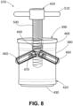
Fig. 8 is a sectional view of the cavity plug ofFig. 6 . - Referring now to the drawings, in which like numerals refer to like elements throughout the several views,
Fig. 1 shows a schematic diagram of agas turbine engine 10 as may be described herein. Thegas turbine engine 10 may include acompressor 15. Thecompressor 15 compresses an incoming flow ofair 20. Thecompressor 15 delivers the compressed flow ofair 20 to a number ofcombustor cans 25. The combustor cans 25 mix the compressed flow ofair 20 with a pressurized flow offuel 30 and ignite the mixture to create a flow ofhot combustion gases 35. Although only a single combustor can 25 is shown, thegas turbine engine 10 may include any number ofcombustor cans 25 positioned in a circumferential array and the like. Alternatively, thecombustor 25 may be an annular combustor. The flow ofcombustion gases 35 is in turn delivered to aturbine 40. The flow ofcombustion gases 35 drives theturbine 40 to produce mechanical work. The mechanical work produced in theturbine 40 drives thecompressor 15 via arotor shaft 45. Theturbine 40 and therotor shaft 45 also may drive anexternal load 50 such as an electrical generator and the like. - The
gas turbine engine 10 may use natural gas, various types of syngas, hydrogen fuel, liquid fuels, and/or other types of fuels and blends thereof. Thegas turbine engine 10 may be any one of a number of different gas turbine engines offered by General Electric Company of Schenectady, New York, including, but not limited to, those such as a 7-series or a 9-series heavy duty gas turbine engine as well as LM6000 and LM9000 aeroderivative gas turbine engines and the like. Thegas turbine engine 10 may be part of a simple cycle or a combined cycle power generation system or other types of generation systems. Thegas turbine engine 10 may have different configurations and may use other types of components. Other types of gas turbine engines also may be used herein. Multiple gas turbine engines, other types of turbines, and other types of power generation equipment also may be used herein together. -
Fig. 2 is a partial sectional view of thecombustor 25. Thecombustor 25 may incorporate a number offuel injectors 52 therein. Thefuel injectors 52 may be combined in afuel nozzle assembly 53. In this example, thefuel injectors 52 may be bundled tube fuel injectors and the like. Thecombustor 25 is at least partially surrounded by anouter casing 54. Theouter casing 54 forms ahigh pressure plenum 56 around thecombustor 25. Thehigh pressure plenum 56 may be in fluid communication with thecompressor 15 or other source for supplying the flow ofair 20 to thecombustor 25. Anend cover 58 is coupled to theouter casing 54. Theend cover 58 may be in fluid communication with the flow offuel 30. - The
fuel injectors 52 extend downstream from theend cover 58. Thefuel injector 52 may be fluidly connected to theend cover 58 so as to receive the flow offuel 30. For example, afluid conduit 60 may provide for fluid communication between theend cover 58 and thefuel injector 52. One end of anannular liner 62 such as a combustion liner and/or a transition duct surrounds adownstream end 64 of thefuel injector 52 so as to at least partially define acombustion chamber 66. Theliner 62 defines ahot gas path 68 for directing thecombustion gases 35 from thecombustion chamber 66. - In operation, the flow of
air 20 is routed towards theend cover 58 where it reverses direction and flows through one or more of thefuel injectors 52. The flow offuel 30 is provided to thefuel injector 52 and the flow offuel 30 and the flow ofair 20 are premixed or combined within thefuel injector 52 before being injected into acombustion chamber 66 for combustion. -
Fig. 3 is a schematic/block view of an illustrative computerizedadditive manufacturing system 100 for manufacturing acomponent 110 on abuild plate 120 positioned on abuild platform 130. Theadditive manufacturing system 100 may be used to createcomponents 110 such as thefuel injectors 52 and other types of hot gas path components. In this example, theadditive manufacturing system 100 is arranged for direct metal laser melting (DMLM), a metal powder additive manufacturing process. It is understood that the general teachings of this disclosure are equally applicable to other forms of additive manufacturing such as binder jet, E-Beam, and the like. Theadditive manufacturing system 100 generally includes a computerized additive manufacturing control system 140 and anadditive manufacturing printer 150. Theadditive manufacturing system 100 executescode 160 that includes a set of computer-executable instructions to physically generate thecomponent 110 on thebuild plate 120 using theadditive manufacturing printer 150. Each additive manufacturing process may use different raw materials in the form of, for example, fine-grain metal powder 175, a stock of which may be held in achamber 170 of theadditive manufacturing printer 150. For example, thecomponent 110 may be made of a metal or a metal alloy. Anapplicator 180 may create a thin layer of araw material 190 spread out as the blank canvas from which each successive slice of thefinal component 110 may be created. In the example shown, a laser orelectron beam 200, positioned above thebuild plate 120, fuses particles for each slice, as defined by thecode 160. Although one laser orelectron beam 200 is shown, it is understood that theadditive manufacturing system 100 may include any number. Various components of theadditive manufacturing printer 150 may move to accommodate the addition of each new layer. - The additive manufacturing control system 140 is shown as being implemented on a
computer 210 as computer program code. To this extent, thecomputer 210 is shown including amemory 220, aprocessor 230, an input/output (I/O) interface 240, and abus 250. Further, thecomputer 210 is shown in communication with an external I/O device/resource 260 and anexternal storage system 270. In general, theprocessor 230 executes computer program code, such as the additive manufacturing control system 140 that may be stored in thememory 220 and/or thestorage system 270 under instructions from thecode 160 representative of thecomponent 110. Thecomputer 210 is only representative of various possible combinations of hardware and software that may be used herein. - The additive manufacturing processes begin with a non-transitory computer readable storage medium (e.g., the
memory 220, thestorage system 270, and the like) storingcode 160 representative of thecomponent 110. As noted, thecode 160 includes a set of computer-executable instructions defining thecomponent 110 that can be used to physically generate thecomponent 110. For example, thecode 160 may include a precisely defined 3D model of thecomponent 110 and may be generated from any of a large variety of well-known computer aided design (CAD) software systems. Theadditive manufacturing system 100 executes thecode 160, dividing thecomponent 110 into a series of thin slices that it assembles using theadditive manufacturing printer 150 in successive layers of powder. In the DMI,M example, each layer may be melted or sintered to the exact geometry defined by thecode 160 and fused to the preceding layer. Subsequently, thecomponent 110 may be subject to any variety of finishing processes, e.g., minor machining, sealing, polishing, assembly to another part, and similar processes. -
Figs. 4 and 5 show acomponent 110 manufactured by theadditive manufacturing system 100. In this example, the component may be a fuel injector 300 similar to thefuel injector 52 described above. Specifically, the fuel injector 300 may be a pre-mixing or a micro-mixing injector 310. Generally described, the micro-mixing injector 310 may have a first plate orwall 320, a second plate orwall 330, and asidewall 340 in-between. A number of pre-mixing ormicro-mixing tubes 350 may extend from thefirst wall 320 to thesecond wall 330. Acentral cavity 360 extends between thefirst wall 320 and thesecond wall 330. Themicro-mixing tubes 350 surround thecentral cavity 360. As described above, when thecomponent 110 is removed from the build plate 120 (shown inFig. 5 ), swarf and other debris may enter thecentral cavity 360. This debris may be difficult to remove and may create operational issues. (By contrast, themicro-mixing tubes 350 are easy to clean in that they extend directly from thefirst wall 320 to thesecond wall 330.) -
Figs. 5-8 show acavity plug 370 as may be described herein. Thecavity plug 370 may be sized to fill and seal thecentral cavity 360 of the micro-mixing injector 310. Thecavity plug 370 may include anouter shell 380. Theouter shell 380 is shown as cylindrical but may take any convenient shape. Theouter shell 380 may be made out of any substantially rigid material such as stainless steel and the like. Theouter shell 380 may be enclosed on a top end or afirst end 390 by atop lid 400 and atop lid seal 410. Thetop lid 400 and thetop lid seal 410 may have a diameter that is larger than the diameter of theouter shell 380 but seals within or on top of the diameter of thecentral cavity 360 through thefirst wall 320 of the micro-mixing injector 310. Theouter shell 380 may be enclosed on a second end or abottom end 420 by abottom flange 430 and abottom flange seal 440. Thebottom flange 430 and thebottom flange seal 440 may have a diameter that is smaller than the diameter of theouter shell 380 but seals within the diameter of thecentral cavity 360 through thesecond wall 330 of the micro-mixing injector 310. Theseals - The
cavity plug 370 may include alocking mechanism 450. Thelocking mechanism 450 may include a pair of pivotinglocking arm 460. The lockingarms 460 may be recessed or contoured to accommodate the shape of thewalls component 110. Each of the lockingarms 460 may pivot about apivot rod 470. Thepivot rods 470 may be attached to theouter shell 380. Each of the lockingarms 460 may pivot along apivot slot 480 in theouter shell 380. The lockingarms 460 may be maneuvered by apivot spring 490. Thepivot spring 490 may be compressed and released by alocking bolt 500. Thelocking bolt 500 may have ahandle 510 for ease of turning. Other types of linear motion devices such as pneumatic or hydraulic cylinder, servos, and the like also may be used. Other components and other configurations may be used herein. - In use, the micro-mixing inj ector 310 or other type of
component 110 is manufactured in theadditive manufacturing system 100 as described above. Before the micro-mixing injector 310 is removed from thebuild plate 120. Thecavity plug 370 may be positioned within thecentral cavity 360. Turning thelocking bolt 500 causes the lockingarms 460 to engage under thefirst wall 320 of the micro-mixing injector 310. The motion causes thetop lid 400 and thetop lid seal 410 to engage on top of and within thecentral cavity 360 through thefirst wall 320 and thebottom flange 430 and thebottom flange seal 440 to engage on top of and within thecentral cavity 360 through thesecond wall 330. This pulling action compresses theseals build plate 120 without fear of contaminating thecentral cavity 360. Thecavity plug 370 thus may be removed. The micro-mixing injector 310 then may be further processed as appropriate. Other components and other configurations may be used herein. - It should be apparent that the foregoing relates only to certain embodiments of this application and resultant patent. Numerous changes and modifications may be made herein by one of ordinary skill in the art without departing from the general spirit and scope of the invention as defined by the following claims and the equivalents thereof.
- Further aspects of the invention are provided by the subject matter of the following clauses:
- 1. A cavity plug for a cavity extending through a first wall of a component manufactured in an additive manufacturing system, the cavity plug comprising: an outer shell; a first seal sized to seal about the cavity extending through the first wall of the component; and a locking mechanism positioned within the outer shell; the locking mechanism comprising a locking arm to engage the first wall and seal the cavity plug in place.
- 2. The cavity plug of any preceding clause, wherein the outer shell comprises a top lid with the first seal thereabout.
- 3. The cavity plug of any preceding clause, wherein the outer shell comprises a first diameter, wherein the top lid comprises a second diameter, and wherein the second diameter is greater than the first diameter.
- 4. The cavity plug of any preceding clause, wherein the component comprises a second wall with the cavity extending therethrough and wherein the outer shell comprises a second seal sized to seal about the cavity extending through the second wall of the component.
- 5. The cavity plug of any preceding clause, wherein the outer shell comprises a bottom flange with the second seal thereabout.
- 6. The cavity plug of any preceding clause, wherein the outer shell comprises a first diameter, wherein the bottom flange comprises a second diameter, and wherein the second diameter is smaller than the first diameter.
- 7. The cavity plug of any preceding clause, wherein the locking arm comprises a pair of locking arms.
- 8. The cavity plug of any preceding clause, wherein the outer shell comprises a pair of pivot slots and wherein the pair of locking arms pivot within the pivot slots.
- 9. The cavity plug of any preceding clause, wherein each of the pair of locking arms pivot about a pivot rod.
- 10. The cavity plug of any preceding clause, wherein the locking mechanism comprises a pivot spring in communication with the pair of locking arms.
- 11. The cavity plug of any preceding clause, wherein the locking mechanism comprises a locking bolt in communication with the pivot spring.
- 12. The cavity plug of any preceding clause, wherein the locking bolt comprises a handle.
- 13. The cavity plug of any preceding clause, wherein the component comprises a fuel injector.
- 14. The cavity plug of any preceding clause, wherein the component comprises a micro-mixing injector.
- 15. A method of manufacturing a component with a cavity therein in an additive manufacturing system, comprising: creating the component on a build plate of the additive manufacturing system; inserting a cavity plug within the cavity to seal the cavity; locking the cavity plug into place via a pair of locking arms within the cavity; and removing the component from the build plate.
- 16. An additive manufacturing system for manufacturing a component with a cavity therein, comprising: a build plate for manufacturing the component thereon; and a cavity plug to seal the cavity; the cavity plug comprises a pair of seals and a locking mechanism with a pair of locking arm to seal the cavity plug within the cavity.
- 17. The additive manufacturing system of any preceding clause, wherein cavity plug comprises an outer shell with a top lid and a first one of the pair of seals thereabout.
- 18. The additive manufacturing system of any preceding clause, wherein the outer shell comprises a bottom flange and a second one of the pair of seals thereabout.
- 19. The additive manufacturing system of any preceding clause, wherein the outer shell comprises a pair of pivot slots and wherein the pair of locking arms pivot within the pivot slots.
- 20. The additive manufacturing system of any preceding clause, wherein the locking mechanism comprises locking bolt and a pivot spring in communication with the pair of locking arms.
Claims (15)
- A cavity plug (370) for a cavity (360) extending through a first wall (320) of a component (110) manufactured in an additive manufacturing system (100), the cavity plug (370) comprising:an outer shell (380);a first seal (410) sized to seal about the cavity (360) extending through the first wall (320) of the component (110); anda locking mechanism (450) positioned within the outer shell (380);the locking mechanism (450) comprising a locking arm (460) to engage the first wall (320) and seal the cavity plug (370) in place.
- The cavity plug (370) of claim 1, wherein the outer shell (380) comprises a top lid (400) with the first seal (410) thereabout.
- The cavity plug (370) of claim 2, wherein the outer shell (380) comprises a first diameter, wherein the top lid (400) comprises a second diameter, and wherein the second diameter is greater than the first diameter.
- The cavity plug (370) of claim 1, wherein the component (110) comprises a second wall (330) with the cavity (360) extending therethrough and wherein the outer shell (380) comprises a second seal (440) sized to seal about the cavity (360) extending through the second wall (330) of the component (110).
- The cavity plug (370) of claim 4, wherein the outer shell (380) comprises a bottom flange (430) with the second seal (440) thereabout.
- The cavity plug (370) of claim 5, wherein the outer shell (380) comprises a first diameter, wherein the bottom flange (430) comprises a second diameter, and wherein the second diameter is smaller than the first diameter.
- The cavity plug (370) of claim 1, wherein the locking arm (460) comprises a pair of locking arms (460).
- The cavity plug (370) of claim 7, wherein the outer shell (380) comprises a pair of pivot slots (480) and wherein the pair of locking arms (460) pivot within the pivot slots (480).
- The cavity plug (370) of claim 8, wherein each of the pair of locking arms (460) pivot about a pivot rod (470).
- The cavity plug (370) of claim 7, wherein the locking mechanism (450) comprises a pivot spring (490) in communication with the pair of locking arms (460).
- The cavity plug (370) of claim 10, wherein the locking mechanism (450) comprises a locking bolt (500) in communication with the pivot spring (490).
- The cavity plug (370) of claim 11, wherein the locking bolt (500) comprises a handle (510).
- The cavity plug (370) of claim 1, wherein the component (110) comprises a fuel injector (300).
- The cavity plug (370) of claim 1, wherein the component (110) comprises a micro-mixing injector (310).
- A method of manufacturing a component (110) with a cavity (360) therein in an additive manufacturing system (100), comprising:creating the component (110) on a build plate (120) of the additive manufacturing system (100);inserting a cavity plug (370) within the cavity (360) to seal the cavity (360);locking the cavity plug (370) into place via a pair of locking arms (460) within the cavity (360); andremoving the component (110) from the build plate (120).
Applications Claiming Priority (1)
| Application Number | Priority Date | Filing Date | Title |
|---|---|---|---|
| US18/479,173 US12636703B2 (en) | 2023-10-02 | 2023-10-02 | Cavity plug additive part removal from build plate |
Publications (2)
| Publication Number | Publication Date |
|---|---|
| EP4534222A1 true EP4534222A1 (en) | 2025-04-09 |
| EP4534222B1 EP4534222B1 (en) | 2026-03-18 |
Family
ID=92712452
Family Applications (1)
| Application Number | Title | Priority Date | Filing Date |
|---|---|---|---|
| EP24199180.1A Active EP4534222B1 (en) | 2023-10-02 | 2024-09-09 | Cavity plug for additive part removal from build plate |
Country Status (4)
| Country | Link |
|---|---|
| US (1) | US12636703B2 (en) |
| EP (1) | EP4534222B1 (en) |
| JP (1) | JP2025072289A (en) |
| CN (1) | CN119747693A (en) |
Citations (4)
| Publication number | Priority date | Publication date | Assignee | Title |
|---|---|---|---|---|
| US20190337056A1 (en) * | 2018-05-01 | 2019-11-07 | Divergent Technologies, Inc. | Apparatus and methods for sealing powder holes in additively manufactured parts |
| WO2020120891A1 (en) * | 2018-12-11 | 2020-06-18 | Addup | Method for cleaning a part produced by an additive manufacturing method with at least one plug and a phase change of a cleaning product |
| US20210299751A1 (en) * | 2020-03-31 | 2021-09-30 | Mitsubishi Heavy Industries, Ltd. | Method of manufacturing fabricated object |
| US20220118514A1 (en) * | 2020-10-19 | 2022-04-21 | General Electric Company | Additively manufactured object using mask over opening for coating |
Family Cites Families (7)
| Publication number | Priority date | Publication date | Assignee | Title |
|---|---|---|---|---|
| US581157A (en) * | 1897-04-20 | Non-refillable bottle | ||
| DE4242154C2 (en) * | 1992-12-14 | 1995-04-20 | United Carr Gmbh Trw | Sealing cover |
| US6872039B2 (en) * | 2003-04-23 | 2005-03-29 | Pivot Point, Incorporated | Self-locking pin |
| CN102318155B (en) * | 2009-02-17 | 2015-08-19 | 泰克莱国际股份有限公司 | A channel device for installing cables |
| US9925609B2 (en) | 2015-07-30 | 2018-03-27 | General Electric Company | Drilling tool and method of machining a conductive work piece |
| US10099276B2 (en) | 2015-12-17 | 2018-10-16 | General Electric Company | Method and assembly for forming components having an internal passage defined therein |
| CN109465448A (en) * | 2018-12-27 | 2019-03-15 | 西安赛隆金属材料有限责任公司 | A kind of anti-powder type bottom plate levelling device and powder bed increasing material manufacturing equipment |
-
2023
- 2023-10-02 US US18/479,173 patent/US12636703B2/en active Active
-
2024
- 2024-08-27 CN CN202411183041.9A patent/CN119747693A/en active Pending
- 2024-09-09 EP EP24199180.1A patent/EP4534222B1/en active Active
- 2024-09-09 JP JP2024154665A patent/JP2025072289A/en active Pending
Patent Citations (4)
| Publication number | Priority date | Publication date | Assignee | Title |
|---|---|---|---|---|
| US20190337056A1 (en) * | 2018-05-01 | 2019-11-07 | Divergent Technologies, Inc. | Apparatus and methods for sealing powder holes in additively manufactured parts |
| WO2020120891A1 (en) * | 2018-12-11 | 2020-06-18 | Addup | Method for cleaning a part produced by an additive manufacturing method with at least one plug and a phase change of a cleaning product |
| US20210299751A1 (en) * | 2020-03-31 | 2021-09-30 | Mitsubishi Heavy Industries, Ltd. | Method of manufacturing fabricated object |
| US20220118514A1 (en) * | 2020-10-19 | 2022-04-21 | General Electric Company | Additively manufactured object using mask over opening for coating |
Also Published As
| Publication number | Publication date |
|---|---|
| EP4534222B1 (en) | 2026-03-18 |
| US12636703B2 (en) | 2026-05-26 |
| JP2025072289A (en) | 2025-05-09 |
| US20250108438A1 (en) | 2025-04-03 |
| CN119747693A (en) | 2025-04-04 |
Similar Documents
| Publication | Publication Date | Title |
|---|---|---|
| EP3115147A1 (en) | Systems and methods for turbine blade repair | |
| CN110712002B (en) | Method for restoring a blade or vane platform | |
| US10174617B2 (en) | Systems and methods for deep tip crack repair | |
| JP2016079984A (en) | Heat exchanger assembly | |
| EP3660269B1 (en) | Cooled hot gas path components including a plurality of nozzles and venturies | |
| US10830050B2 (en) | Unitary body turbine shrouds including structural breakdown and collapsible features | |
| US20250216077A1 (en) | Additively manufactured tapered transition portion and aft frame for replacement of existing combustor parts | |
| US20250108438A1 (en) | Cavity plug additive part removal from build plate | |
| US11619172B1 (en) | Detonation combustion systems | |
| US20210246829A1 (en) | Hot gas path components including aft end exhaust conduits and aft end flanges | |
| EP3660270B1 (en) | Cooled airfoil including plurality of nozzles and venturi | |
| JP2025114474A (en) | Axial fuel stage immersion injector with internal cooling | |
| EP4534909A1 (en) | Aft inner cap plate removal method and tooling for a combustor with micromixer tubes | |
| EP3315228A1 (en) | Additively manufactured component for a gas powered turbine | |
| JP2025093861A (en) | Method for repairing an airfoil having tip cooling passages - Patents.com | |
| GB2550856B (en) | Method of manufacture | |
| US11035248B1 (en) | Unitary body turbine shrouds including shot peen screens integrally formed therein and turbine systems thereof | |
| CA3101621C (en) | System and method for performing operations on an engine | |
| US20250216075A1 (en) | Additively manufactured combustor with air re-use from aft frame to axial fuel stage injector(s) | |
| EP3657074A1 (en) | Burner lance for a gas turbine combustor; method for manufacturing this burner lance and gas turbine assembly comprising this burner lance | |
| US12281794B1 (en) | Combustor body and axial fuel stage immersed injectors additively manufactured with different materials | |
| EP4538596A1 (en) | Aft inner cap plate removal method and tooling for a combustor with micromixer tubes | |
| Wood | RS-68-What and how | |
| CN115962481A (en) | Additive one-piece hole cooled combustor dome | |
| CN113531585A (en) | Gas turbine combustor and method for manufacturing fuel nozzle |
Legal Events
| Date | Code | Title | Description |
|---|---|---|---|
| PUAI | Public reference made under article 153(3) epc to a published international application that has entered the european phase |
Free format text: ORIGINAL CODE: 0009012 |
|
| STAA | Information on the status of an ep patent application or granted ep patent |
Free format text: STATUS: THE APPLICATION HAS BEEN PUBLISHED |
|
| AK | Designated contracting states |
Kind code of ref document: A1 Designated state(s): AL AT BE BG CH CY CZ DE DK EE ES FI FR GB GR HR HU IE IS IT LI LT LU LV MC ME MK MT NL NO PL PT RO RS SE SI SK SM TR |
|
| RAP3 | Party data changed (applicant data changed or rights of an application transferred) |
Owner name: GE VERNOVA TECHNOLOGY GMBH |
|
| STAA | Information on the status of an ep patent application or granted ep patent |
Free format text: STATUS: REQUEST FOR EXAMINATION WAS MADE |
|
| 17P | Request for examination filed |
Effective date: 20250924 |
|
| RIC1 | Information provided on ipc code assigned before grant |
Ipc: B22F 5/10 20060101AFI20251028BHEP Ipc: B22F 5/00 20060101ALI20251028BHEP Ipc: B22F 10/28 20210101ALI20251028BHEP Ipc: B22F 10/60 20210101ALI20251028BHEP Ipc: B33Y 10/00 20150101ALI20251028BHEP Ipc: B33Y 40/20 20200101ALI20251028BHEP Ipc: F23R 3/28 20060101ALN20251028BHEP |
|
| GRAP | Despatch of communication of intention to grant a patent |
Free format text: ORIGINAL CODE: EPIDOSNIGR1 |
|
| STAA | Information on the status of an ep patent application or granted ep patent |
Free format text: STATUS: GRANT OF PATENT IS INTENDED |
|
| INTG | Intention to grant announced |
Effective date: 20251223 |
|
| GRAS | Grant fee paid |
Free format text: ORIGINAL CODE: EPIDOSNIGR3 |
|
| GRAA | (expected) grant |
Free format text: ORIGINAL CODE: 0009210 |
|
| STAA | Information on the status of an ep patent application or granted ep patent |
Free format text: STATUS: THE PATENT HAS BEEN GRANTED |
|
| AK | Designated contracting states |
Kind code of ref document: B1 Designated state(s): AL AT BE BG CH CY CZ DE DK EE ES FI FR GB GR HR HU IE IS IT LI LT LU LV MC ME MK MT NL NO PL PT RO RS SE SI SK SM TR |
|
| REG | Reference to a national code |
Ref country code: CH Ref legal event code: F10 Free format text: ST27 STATUS EVENT CODE: U-0-0-F10-F00 (AS PROVIDED BY THE NATIONAL OFFICE) Effective date: 20260318 Ref country code: GB Ref legal event code: FG4D |
|
| REG | Reference to a national code |
Ref country code: CH Ref legal event code: R17 Free format text: ST27 STATUS EVENT CODE: U-0-0-R10-R17 (AS PROVIDED BY THE NATIONAL OFFICE) Effective date: 20260327 |
|
| REG | Reference to a national code |
Ref country code: DE Ref legal event code: R096 Ref document number: 602024003280 Country of ref document: DE |
|
| REG | Reference to a national code |
Ref country code: IE Ref legal event code: FG4D |
|
| PG25 | Lapsed in a contracting state [announced via postgrant information from national office to epo] |
Ref country code: RS Free format text: LAPSE BECAUSE OF FAILURE TO SUBMIT A TRANSLATION OF THE DESCRIPTION OR TO PAY THE FEE WITHIN THE PRESCRIBED TIME-LIMIT Effective date: 20260618 |
|
| PG25 | Lapsed in a contracting state [announced via postgrant information from national office to epo] |
Ref country code: GR Free format text: LAPSE BECAUSE OF FAILURE TO SUBMIT A TRANSLATION OF THE DESCRIPTION OR TO PAY THE FEE WITHIN THE PRESCRIBED TIME-LIMIT Effective date: 20260619 |
|
| REG | Reference to a national code |
Ref country code: LT Ref legal event code: MG9D |
|
| PG25 | Lapsed in a contracting state [announced via postgrant information from national office to epo] |
Ref country code: LT Free format text: LAPSE BECAUSE OF FAILURE TO SUBMIT A TRANSLATION OF THE DESCRIPTION OR TO PAY THE FEE WITHIN THE PRESCRIBED TIME-LIMIT Effective date: 20260318 |
|
| PG25 | Lapsed in a contracting state [announced via postgrant information from national office to epo] |
Ref country code: NO Free format text: LAPSE BECAUSE OF FAILURE TO SUBMIT A TRANSLATION OF THE DESCRIPTION OR TO PAY THE FEE WITHIN THE PRESCRIBED TIME-LIMIT Effective date: 20260618 |
|
| PG25 | Lapsed in a contracting state [announced via postgrant information from national office to epo] |
Ref country code: SE Free format text: LAPSE BECAUSE OF FAILURE TO SUBMIT A TRANSLATION OF THE DESCRIPTION OR TO PAY THE FEE WITHIN THE PRESCRIBED TIME-LIMIT Effective date: 20260318 Ref country code: FI Free format text: LAPSE BECAUSE OF FAILURE TO SUBMIT A TRANSLATION OF THE DESCRIPTION OR TO PAY THE FEE WITHIN THE PRESCRIBED TIME-LIMIT Effective date: 20260318 |
|
| PG25 | Lapsed in a contracting state [announced via postgrant information from national office to epo] |
Ref country code: HR Free format text: LAPSE BECAUSE OF FAILURE TO SUBMIT A TRANSLATION OF THE DESCRIPTION OR TO PAY THE FEE WITHIN THE PRESCRIBED TIME-LIMIT Effective date: 20260318 |
|
| REG | Reference to a national code |
Ref country code: NL Ref legal event code: MP Effective date: 20260318 |
|
| PG25 | Lapsed in a contracting state [announced via postgrant information from national office to epo] |
Ref country code: LV Free format text: LAPSE BECAUSE OF FAILURE TO SUBMIT A TRANSLATION OF THE DESCRIPTION OR TO PAY THE FEE WITHIN THE PRESCRIBED TIME-LIMIT Effective date: 20260318 |
|
| PG25 | Lapsed in a contracting state [announced via postgrant information from national office to epo] |
Ref country code: BG Free format text: LAPSE BECAUSE OF FAILURE TO SUBMIT A TRANSLATION OF THE DESCRIPTION OR TO PAY THE FEE WITHIN THE PRESCRIBED TIME-LIMIT Effective date: 20260318 |