EP4534218A1 - Hot-pressing device, production method for hot-pressed molded article, and hot-pressed molded article - Google Patents
Hot-pressing device, production method for hot-pressed molded article, and hot-pressed molded article Download PDFInfo
- Publication number
- EP4534218A1 EP4534218A1 EP23811897.0A EP23811897A EP4534218A1 EP 4534218 A1 EP4534218 A1 EP 4534218A1 EP 23811897 A EP23811897 A EP 23811897A EP 4534218 A1 EP4534218 A1 EP 4534218A1
- Authority
- EP
- European Patent Office
- Prior art keywords
- sheet
- die
- press
- hot press
- formed product
- Prior art date
- Legal status (The legal status is an assumption and is not a legal conclusion. Google has not performed a legal analysis and makes no representation as to the accuracy of the status listed.)
- Pending
Links
Images









Classifications
-
- B—PERFORMING OPERATIONS; TRANSPORTING
- B21—MECHANICAL METAL-WORKING WITHOUT ESSENTIALLY REMOVING MATERIAL; PUNCHING METAL
- B21D—WORKING OR PROCESSING OF SHEET METAL OR METAL TUBES, RODS OR PROFILES WITHOUT ESSENTIALLY REMOVING MATERIAL; PUNCHING METAL
- B21D22/00—Shaping without cutting, by stamping, spinning, or deep-drawing
- B21D22/20—Deep-drawing
- B21D22/26—Deep-drawing for making peculiarly, e.g. irregularly, shaped articles
-
- B—PERFORMING OPERATIONS; TRANSPORTING
- B21—MECHANICAL METAL-WORKING WITHOUT ESSENTIALLY REMOVING MATERIAL; PUNCHING METAL
- B21D—WORKING OR PROCESSING OF SHEET METAL OR METAL TUBES, RODS OR PROFILES WITHOUT ESSENTIALLY REMOVING MATERIAL; PUNCHING METAL
- B21D22/00—Shaping without cutting, by stamping, spinning, or deep-drawing
- B21D22/02—Stamping using rigid devices or tools
- B21D22/022—Stamping using rigid devices or tools by heating the blank or stamping associated with heat treatment
-
- B—PERFORMING OPERATIONS; TRANSPORTING
- B21—MECHANICAL METAL-WORKING WITHOUT ESSENTIALLY REMOVING MATERIAL; PUNCHING METAL
- B21D—WORKING OR PROCESSING OF SHEET METAL OR METAL TUBES, RODS OR PROFILES WITHOUT ESSENTIALLY REMOVING MATERIAL; PUNCHING METAL
- B21D22/00—Shaping without cutting, by stamping, spinning, or deep-drawing
- B21D22/20—Deep-drawing
-
- B—PERFORMING OPERATIONS; TRANSPORTING
- B21—MECHANICAL METAL-WORKING WITHOUT ESSENTIALLY REMOVING MATERIAL; PUNCHING METAL
- B21D—WORKING OR PROCESSING OF SHEET METAL OR METAL TUBES, RODS OR PROFILES WITHOUT ESSENTIALLY REMOVING MATERIAL; PUNCHING METAL
- B21D22/00—Shaping without cutting, by stamping, spinning, or deep-drawing
- B21D22/20—Deep-drawing
- B21D22/208—Deep-drawing by heating the blank or deep-drawing associated with heat treatment
-
- B—PERFORMING OPERATIONS; TRANSPORTING
- B21—MECHANICAL METAL-WORKING WITHOUT ESSENTIALLY REMOVING MATERIAL; PUNCHING METAL
- B21D—WORKING OR PROCESSING OF SHEET METAL OR METAL TUBES, RODS OR PROFILES WITHOUT ESSENTIALLY REMOVING MATERIAL; PUNCHING METAL
- B21D22/00—Shaping without cutting, by stamping, spinning, or deep-drawing
- B21D22/20—Deep-drawing
- B21D22/22—Deep-drawing with devices for holding the edge of the blanks
-
- B—PERFORMING OPERATIONS; TRANSPORTING
- B21—MECHANICAL METAL-WORKING WITHOUT ESSENTIALLY REMOVING MATERIAL; PUNCHING METAL
- B21D—WORKING OR PROCESSING OF SHEET METAL OR METAL TUBES, RODS OR PROFILES WITHOUT ESSENTIALLY REMOVING MATERIAL; PUNCHING METAL
- B21D24/00—Special deep-drawing arrangements in, or in connection with, presses
-
- B—PERFORMING OPERATIONS; TRANSPORTING
- B21—MECHANICAL METAL-WORKING WITHOUT ESSENTIALLY REMOVING MATERIAL; PUNCHING METAL
- B21D—WORKING OR PROCESSING OF SHEET METAL OR METAL TUBES, RODS OR PROFILES WITHOUT ESSENTIALLY REMOVING MATERIAL; PUNCHING METAL
- B21D37/00—Tools as parts of machines covered by this subclass
- B21D37/16—Heating or cooling
Definitions
- the present disclosure relates to a hot press apparatus, a method for manufacturing a hot press-formed product, and a hot press-formed product.
- Patent Document 1 discloses a bumper reinforcement material that is provided with a small recessed portion and a large recessed portion surrounding the small recessed portion for the purpose of increasing a peak load or an energy absorption amount.
- Patent Document 2 discloses a technique for press-forming a sheet material into a hat-shaped product having an unevenness in its top surface.
- a forming process of the unevenness in the top surface of the formed product and a forming process of a shoulder portion adjacent to the top surface are performed simultaneously, these forming processes interfere with each other, and thus it is difficult to perform the forming processes.
- the forming process of the unevenness in the top surface of the formed product is performed in advance, and after the unevenness is restrained by a punch and a die pad, the shoulder of the formed product is formed by a punch and a die. In this way, the main point of Patent Document 2 is that the two forming processes are not performed simultaneously.
- a hot press-formed product 100 obtained by a hot press apparatus and a method for manufacturing a hot press-formed product according to the present embodiment will be described with reference to FIG. 1 .
- FIG. 1 is a perspective view of the hot press-formed product 100 and is a view including a cut surface orthogonal to a longitudinal direction at the central position on the long hot press-formed product 100 in the longitudinal direction. This cut surface is also a cross section in a press direction P.
- the hot press-formed product 100 of the present embodiment is the long hot press-formed product 100 and includes a first sheet portion 110 that extends in the longitudinal direction of the hot press-formed product 100, a second sheet portion 120 that extends in the longitudinal direction of the hot press-formed product 100 and is inclined with respect to the first sheet portion 110, and a ridge portion 130 that smoothly connects the first sheet portion 110 and the second sheet portion 120 and extends in the longitudinal direction of the hot press-formed product 100.
- the first sheet portion 110 is provided with a recessed portion 140.
- a direction parallel to the longitudinal direction of the hot press-formed product 100 is defined as a length direction of the recessed portion 140, the recessed portion 140 extends in the length direction of the recessed portion 140.
- FIG. 2 shows an end view of a cut portion of the hot press-formed product 100 viewed in a cross section at a plane orthogonal to the longitudinal direction of the hot press-formed product 100 in the longitudinal direction of the hot press-formed product 100 shown in FIG. 1 .
- the recessed portion 140 is recessed in a direction perpendicular to the sheet surface of the first sheet portion 110 as will be described below. In the example of FIG. 2 , the recessed portion 140 is recessed with respect to the first sheet portion 110 toward a side on which the second sheet portion 120 is located (a side of the first sheet portion sheet surface 110b).
- the recessed portion 140 has a bottom portion 141, a pair of side portions 142, a pair of bottom portion side ridge portions 143, and a pair of side portion side ridge portions 144.
- the bottom portion 141 of the recessed portion is connected at end portions thereof to the side portions 142 via the pair of bottom portion side ridge portions 143.
- Each side portion 142 is connected to the first sheet portion 110 via the side portion side ridge portion 144.
- the bottom portion 141, the side portion 142, the bottom portion side ridge portion 143, and the side portion side ridge portion 144 extend in the length direction of the recessed portion 140.
- the bottom portion 141 of the recessed portion 140 has a bottom portion inner surface 141a located on an inner side of the recessed portion 140 (on a side of the side portion 142) and a bottom portion outer surface 141b on a side opposite to the bottom portion inner surface 141a. That is, the bottom portion inner surface 141a constitutes a part of the inner surface of the recessed portion 140.
- the recessed portion 140 is a portion of the first sheet portion 110 which is recessed toward the side on which the second sheet portion 120 is located (the side of the first sheet portion sheet surface 110b).
- the recessed portion 140 may be a portion of the first sheet portion 110 which is recessed toward a side opposite to the side on which the second sheet portion 120 is located (a side of the first sheet portion sheet surface 110a). That is, the recessed portion provided in the first sheet portion 110 may be recessed toward a side of the ridge outer surface 130a (the outside of the hot press-formed product 100) or a side of the ridge inner surface 130b (the inside of the hot press-formed product 100).
- a distance between the boundary gb1 of the recessed portion and the boundary gb2 of the recessed portion is defined as a width w of the recessed portion 140.
- the width w of the recessed portion 140 does not need to be constant in the longitudinal direction of the hot press-formed product 100.
- the width w of the recessed portion 140 is preferably 10 mm to 52 mm in order to improve the compressive axial force performance in the direction along the Z coordinate axis or the moment bending performance around the direction along the X coordinate axis shown in FIG. 1 and the like.
- the width w of the recessed portion 140 is preferably smaller than a length of the recessed portion 140 in an extending direction.
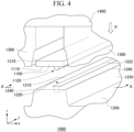
- FIG. 4 shows an example of the press apparatus (the hot press apparatus) used in the method for manufacturing a hot press-formed product according to the present embodiment.
- the press apparatus 1000 shown in FIG. 4 includes a first die 1100, a second die 1200, and a third die 1300 as press dies.
- the first die 1100 and the second die 1200 are movable relative to each other in the press direction P.
- a workpiece (a blank) is sandwiched between the first die 1100 and the second die 1200.
- the third die 1300 is disposed adjacent to the first die 1100 in the direction along the X coordinate axis and is movable relative to the first die 1100 and the second die 1200.
- the third die 1300 is movable in the press direction P relative to the first die 1100 and the second die 1200. Further, a refrigerant flow path (not shown) is provided inside the second die 1200 of the press apparatus 1000.
- the press direction P in the press apparatus 1000 is a negative direction on the Y coordinate axis.
- the X coordinate axis, the Y coordinate axis, and the Z coordinate axis in FIG. 4 are orthogonal to each other.
- the first die 1100 has a press surface 1110 and a protrusion 1120 provided on the press surface 1110.
- the protrusion 1120 has a bottom surface portion 1121 and a pair of side surface portions 1122.
- the bottom surface portion 1121 is connected at end portions thereof to the side surface portions 1122 via a pair of bottom surface portion side ridge portions 1123.
- the protrusion 1120 protrudes in the negative direction on the Y coordinate axis.
- Each of the side surface portions 1122 is connected to a holding surface portion 1130 of the press surface 1110 excluding the protrusion 1120 via a side surface portion side ridge portion 1124.
- the second die 1200 has a press surface (a top surface) 1210 and a groove portion (a recessed surface portion) 1220 provided in the press surface 1210. That is, the second die 1200 has the groove portion 1220 in the top surface thereof.
- the groove portion 1220 has a bottom surface portion 1221, a pair of side surface portions 1222, a pair of bottom surface portion side ridge portions 1223, and a pair of side surface portion side ridge portions 1224.
- the bottom surface portion 1221 is connected at end portions thereof to the side surface portions 1222 via the pair of bottom surface portion side ridge portions 1223.
- the groove portion 1220 has a shape recessed in the negative direction on the Y coordinate axis.
- the third die 1300 has a press surface 1310.
- the press surface 1310 extends in a direction along the Z coordinate axis in FIG. 4 .
- the first die 1100 and the third die 1300 are disposed to face the second die 1200 in the press direction P.
- the first die 1100 is disposed facing the top surface of the second die 1200.
- the first die 1100 is defined as a die pad
- the second die 1200 is defined as a punch
- the third die 1300 is defined as a die.
- the temperature of the workpiece 1 at the start of press forming may be 600°C to 800°C.
- a pressing force may be 0.4 to 22.0 MPa. More preferably, the pressing force may be 0.4 to 4.4 MPa. This allows the workpiece to be formed while the deformation resistance is low, and further allows the forming load of the first die 1100 to be set to the minimum load force, resulting in reduced die costs.
- two third dies 1300 are shown in an X coordinate axis direction. These two third dies 1300 may be connected to each other in the X coordinate axis direction.
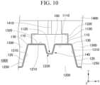
- FIG. 10 shows a state in which the workpiece is sandwiched by the dies and the third die 1300 is moved to the bottom dead point.
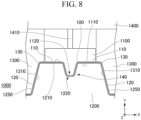
- the workpiece is sandwiched by the second die 1200 and the third die 1300, and the second sheet portion 120 is formed between the second die 1200 and the third die 1300, thereby completing the press forming.
- the first sheet portion 110, the second sheet portion 120, the ridge portion 130, and the recessed portion 140 are formed in the hot press-formed product 100.
- the third die 1300 includes the step portion 1320, the first die 1100 comes into contact with the third die 1300 in the press direction P at a bottom dead point of a forming process. As a result, the first die 1100 is pressed against the third die 1300, and thus it is possible to suppress necking even in a case in which the pressing force of the first die 1100 is insufficient. At this time, the support portion 1410 is deformed to be contracted in the press direction P.
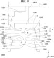
- FIG. 11 another form of the press apparatus 1000 is shown in FIG. 11 .
- the press apparatus 1000 in FIG. 11 is also a schematic end view of a cut portion of the press apparatus shown in FIG. 4 viewed in a cross section at cross section line A-A in a direction along the Z coordinate axis, similar to FIG. 5 and the like.
- the third die 1300 is provided on only one side.
- the third die 1300 has the step portion 1320.
- the first die 1100 also has a press surface 1140 on a side opposite to the third die 1300 in the X axis direction.
- the press surface 1140 is provided to be connected to the press surface 1110 of the first die 1100.
- the press surface 1140 extends in a direction along the Z coordinate axis.
- the press apparatus 1000 shown in FIG. 11 has the same configuration as the press apparatus 1000 shown in FIG. 9 , except that the third die 1300 is provided on only one side, and therefore a description thereof will be omitted here. That is, the configuration of the press apparatus 1000 according to the FIG. 9 can be applied to the press apparatus 1000 shown in FIG. 11 .
- the press apparatus 1000 in FIG. 11 has an advantage that an area for arranging a pressing mechanism of the third die 1300 on an upper side of the press apparatus 1000 can be increased, allowing for some likelihood in the press load design.
- press forming may be performed such that a ratio of an area of the recessed portion 140 to an area of the first sheet portion 110 is 30% or more when viewed in a plane in a direction perpendicular to the sheet surface of the first sheet portion 110.
- the direction perpendicular to the sheet surface of the first sheet portion 110 means a direction, on an imaginary plane that includes the shortest straight line connecting the boundary gb1 and the boundary gb2 and on which a cross-sectional line length of the recessed portion 140 is the smallest when viewed in a cross section, orthogonal to the straight line connecting the boundary gb1 and the boundary gb2.
- the cross-sectional line length of the recessed portion 140 can be measured by creating a 3D model on the basis of three-dimensional shape measurement of the hot press-formed product 100 and deriving the plane in which the cross-sectional line length is the smallest.
- the three-dimensional shape measurement described in the present embodiment can be performed using a 3D scanner such as Atos (manufactured by GOM).
- press forming may be performed such that the maximum depth dmax in a depth d of the recessed portion 140 in the press direction P is 15 mm or more.
- the depth d of the recessed portion 140 means a depth in the press direction P.
- the press direction P is a direction perpendicular to the sheet surface of the first sheet portion 110.
- the maximum depth dmax means the maximum value of the depth d of the recessed portion 140 in the entire recessed portion 140. Since the maximum depth dmax is 15 mm or more, it is possible to obtain an effect of improving the compressive axial force performance in the direction along the Z coordinate axis or the moment bending performance around the direction along the X coordinate axis shown in FIG. 1 and the like.
- the depth of the recessed portion 140 means a distance from the straight line in the direction perpendicular to the sheet surface of the first sheet portion 110 described above to the bottom portion inner surface 141a.
- the curve C corresponds to the shape of the inner surface of the recessed portion 140 in this cross section.
- the curve C has a point iP1 and a point iP2, which are one end points of the side portion 142, between the boundary gb1 or the boundary gb2 and the point pd.
- the point iP1 and the point iP2 are also the R ends of the side portion side ridge portion 144.
- the ratio of the area of the recessed portion 140 to the area of the first sheet portion 110 may be 30% or more when viewed in a plane in a direction perpendicular to the sheet surface of the first sheet portion 110.
- the area of the first sheet portion 110 is an area of a portion including the recessed portion 140 and excluding the second sheet portion 120 and the ridge portion 130 between the first sheet portion 110 and the second sheet portion 120.
- the area of the first sheet portion 110 is defined as an area of the range surrounded by the boundary between the ridge portion 130 and the first sheet portion 110 and the end portions of the first sheet portion 110 in the longitudinal direction in a plan view in a direction perpendicular to the sheet surface of the first sheet portion 110.
- the boundary between the first sheet portion 110 and the ridge portion 130 can be specified by creating a 3D model on the basis of three-dimensional shape measurement of the hot press-formed product 100 and detecting the boundary between the first sheet portion 110 and the ridge portion 130 from this 3D model.
- the area of the recessed portion 140 is defined as an area of the range on a side of the recessed portion 140 surrounded by the boundary between the side portion side ridge portion 144 and the first sheet portion 110.
- the sheet thicknesses of the first sheet portion 110 and the recessed portion 140 are measured by creating a 3D model on the basis of three-dimensional shape measurement of the hot press-formed product 100 and detecting the sheet thickness from this 3D model as described above.
- the maximum distance in the press direction from the press surface 1110 to the protrusion 1120 may be 15 mm or more.
- the press direction intersects with the press surface 1110.
- the maximum distance in the press direction from the press surface 1110 to the protrusion 1120 means the maximum distance in the press direction from the holding surface portion 1130 to the protrusion 1120.
- first die 2100 processes the second sheet portion 120 and the flange portion connected to the second sheet portion 120 while clamping them together with the third die 2300 during press forming. Since the fourth die 2400 is further provided, there is an effect of suppressing the occurrence of wrinkles in the flange portion.
- the third die 2300 is connected to a slide plate 1400.
- the first die 2100 is connected to the slide plate 1400 via a support portion 1410 (a spring or a piston).
- a recessed portion 250 shallower than a recessed portion 240 may be further provided in a first sheet portion 210.
- the hot press-formed product 100 having two second sheet portions 120 is used as an example for explanation, but the hot press-formed product according to the present disclosure may also have the second sheet portion 120 on only one side of the first sheet portion 110.
- 14B tensile test is obtained from the first sheet portion 110 or the second sheet portion 120 of the hot press-formed product 100, and the tensile strength of this sample is measured using a universal testing machine or a hydraulic servo type strength testing machine in accordance with a method conforming to JIS Z 2241, and this tensile strength is regarded as the tensile strength of the hot press-formed product 100.
- a micro tensile test piece may be used as the sample.
- the width or sheet thickness of a parallel portion is preferably 0.2 to 2.0 mm, and a test piece shape formed such that a uniform load is applied within the parallel portion of the tensile test is preferable.
- the test piece is preferably machined by wire cut electric discharge machining.
- the micro tensile test piece for example, the test piece in the Journal of the Japan Welding Society, Vol. 75 (2006), No. 6, pp. 461-465 (https://www.jstage.jst.go.jp/article/jjws175/6/75 6 461/_pdf/-char/ja) can be used.
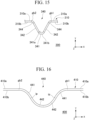
- the recessed portion may have a V-shaped cross-sectional shape including a curve in part, as shown in FIG. 15 , or a cross-sectional shape including a curve, as shown in FIG. 16 .
- a distance between the boundary gb1 and the boundary gb2 is defined as a width of the recessed portion 340.
- the definition of the curve corresponding to the shape of the recessed portion is the same as that in the above embodiment.
- a recessed portion 440 does not have flat side portions as illustrated in FIG. 3 , but rather includes a curve that corresponds to the shape of the inner surface of the recessed portion 440.
- the curve includes a curved portion 441 and a curved portion 442, and an intersection point of the curved portion 441 and the curved portion 442 is a point ip.
- FIGS. 17 to 23 show modification examples of the recessed portion provided in the first sheet portion.
- FIGS. 17 to 23 schematically show only the shape of the recessed portion provided in the first sheet portion.
- the press-formed product according to the above embodiment is preferably used as a hot press-formed product for a vehicle, such as a front bumper reinforcement, a rear bumper reinforcement, a side sill outer, a side sill inner, a door impact beam, a front side member, and a rear side member.
- Example 1 a three-point bending test was performed in a simulation on the hot press-formed product having three recessed portions as shown in FIG. 14 .
- the sheet thickness of a workpiece was set to 1.2 mm, and the tensile strength of the workpiece was set to a 2000 MPa class.
- the conditions for the simulation of the three-point bending test three-point bending in which the center of a member was pressed down statically was performed, and the sheet thickness of the central recessed portion of the member was set to a sheet thickness obtained by the forming simulation.
- the span of a receiving jig for the three-point bending was set to 1000 mm.
- the area ratio of the recessed portions was set to 40%, the maximum depth was set to 15 mm, and the width was set to 35 mm.
- the angle between the side portion of the recessed portions and the press direction during press forming was changed as shown in Table 1.
- the sheet thickness reduction rate at the recessed portion and the component performance were investigated. The results are shown in Table 1.
- (ta - tmin)/ta is defined as the sheet thickness reduction rate at the recessed portion.
- the sheet thickness reduction rate at the recessed portion can be calculated by dividing the sheet thickness reduced at a portion of the recessed portion at which the sheet thickness is reduced the most by the sheet thickness of the first sheet portion in the simulation.
- the yield strength of the member for evaluating the member performance was calculated from the simulation results of the three-point bending test.
- the yield strength is a value obtained by dividing a load, which an impactor pressing down in the three-point bending test receives from the test piece, by a weight, and this is used to evaluate the component performance.
- the load is a load that the impactor receives from the test piece
- the weight is a weight of the hot press-formed product.
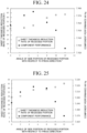
- FIG. 24 shows the results of this simulation. According to FIG. 24 , it was confirmed that the sheet thickness reduction rate can be suppressed by setting the angle of the side portion of the recessed portion to 8° or less with respect to the press direction. It was also found that, when the angle of the side portion of the recessed portion is in the range of 2° to 8° with respect to the press direction, a high component performance of 7.96 kN/kg or more, which is a target component performance, can be achieved. It was also found that, when the angle of the side portion of the recessed portion is 2° or more with respect to the press direction, the press-formed product can be easily released from the die.
- Example 2 a three-point bending test was performed in a simulation on the hot press-formed product having one recessed portion as shown in FIG. 1 .
- the sheet thickness of a workpiece was set to 2.01 mm, and the tensile strength of the workpiece was set to a 2000 MPa class.
- the conditions for the simulation of the three-point bending test three-point bending in which the center of a member was pressed down statically was performed, and the sheet thickness of the central recessed portion of the member was set to a sheet thickness obtained by the forming simulation.
- the span of a receiving jig for the three-point bending was set to 1000 mm.
- the area ratio of the recessed portions was set to 35%, the maximum depth was set to 20 mm, and the width was set to 35 mm.
- the angle between the side portion of the recessed portions and the press direction during press forming was changed as shown in Table 2, and the sheet thickness reduction rate at the recessed portion and the component performance (the yield strength) were investigated.
- the results are shown in Table 2.
- the definitions and calculation methods of the sheet thickness reduction rate at the recessed portion and the component performance are the same as those in Example 1.
- the definitions of the load and the like in Table 2 are the same as those in Table 1.
- the sheet thickness of the workpiece, the number of recessed portions, the tensile strength of the workpiece, and the pad pressure during forming (the pressing force of the first die) were changed, the three-point bending test of the test piece was performed in a simulation, and an overall evaluation was performed from the member yield strength performance and the die cost.
- the height of the second sheet portion was set to 65 mm
- the width of the first sheet portion was set to 100 mm
- the width of the recessed portion was set to 40 mm
- the depth of the recessed portion was set to 23 mm.
- the angle of the side portion of the recessed portion was set to 5° with respect to the press direction.
Landscapes
- Engineering & Computer Science (AREA)
- Mechanical Engineering (AREA)
- Physics & Mathematics (AREA)
- Thermal Sciences (AREA)
- Shaping Metal By Deep-Drawing, Or The Like (AREA)
- Mounting, Exchange, And Manufacturing Of Dies (AREA)
- Forging (AREA)
Abstract
Description
- The present disclosure relates to a hot press apparatus, a method for manufacturing a hot press-formed product, and a hot press-formed product.
- Priority is claimed on
Japanese Patent Application No. 2022-085778, filed May 26, 2022 - In the related art, as a frame member of an automobile, a member obtained by processing a sheet shaped member made of a metal into a predetermined cross-sectional shape has been used. In a case in which an impact from a collision is applied to a product having a frame member, the frame member is required to achieve a desired deformation mode and efficiently absorb the impact. For example,
Patent Document 1 discloses a bumper reinforcement material that is provided with a small recessed portion and a large recessed portion surrounding the small recessed portion for the purpose of increasing a peak load or an energy absorption amount. - Such a frame member is required to be lightweight and have sufficient load capacity. Furthermore, in recent years, with the stricter collision safety standards and the stricter fuel efficiency regulations for a vehicle such as an automobile, there is a demand for a high-strength and lightweight member. In order to meet such a demand, progress is being made in the development of a lightweight frame member that employs so-called a high-strength material having high tensile strength.
-
Patent Document 2 discloses a technique for press-forming a sheet material into a hat-shaped product having an unevenness in its top surface. However, if a forming process of the unevenness in the top surface of the formed product and a forming process of a shoulder portion adjacent to the top surface are performed simultaneously, these forming processes interfere with each other, and thus it is difficult to perform the forming processes. InPatent Document 2, the forming process of the unevenness in the top surface of the formed product is performed in advance, and after the unevenness is restrained by a punch and a die pad, the shoulder of the formed product is formed by a punch and a die. In this way, the main point ofPatent Document 2 is that the two forming processes are not performed simultaneously. -
- Patent Document 1:
Japanese Patent No. 5329188 - Patent Document 2:
Japanese Unexamined Patent Application, First Publication No. 2020-075275 - In a case in which a hat-shaped product or groove-shaped member having a groove portion in its top surface is formed through hot press, if the method of
Patent Document 2 is applied to the hot press, the hot press will be executed twice. In a case in which the forming process is performed through a single hot press, it is conceivable to form a groove portion in a heated sheet material using a die pad and a punch, and then form a shoulder using a punch and a die. In this case, however, two problems arise. Firstly, in a case in which the groove portion is formed via a spring as inPatent Document 2, the force of the spring is weak, and therefore the die pad cannot reach a bottom dead point of a forming process, and the groove portion cannot be formed into a desired shape (a shape that follows the groove portion at the top portion of the punch). Secondly, even if the die pushes the die pad to reach the bottom dead point of the forming process, a localized reduction in sheet thickness occurs in the groove portion of the formed product. Until the die reaches the bottom dead point of the forming process, a workpiece between the groove portion at the top portion of the punch and the die pad is not in uniform contact with the die, causing temperature variation in the workpiece. The reduction in sheet thickness occurs because a locally softened portion caused by the temperature variation in the workpiece is preferentially stretched when the die and die pad reach the bottom dead point of the forming process. - The present disclosure has been made in view of the above. An object of the present disclosure is to provide a hot press apparatus capable of suppressing a reduction in sheet thickness and necking at a recessed portion of a hot press-formed product formed by a die pad, a method for manufacturing a hot press-formed product using the apparatus, and a hot press-formed product in which a reduction in sheet thickness and necking at a recessed portion of a press-formed product are suppressed.
-
- (1) A hot press apparatus according to one aspect of the present disclosure includes
- a punch, a die, and a die pad,
- in which a groove portion is provided in a top surface of the punch,
- in which, in a cross section in a press direction, an angle between a wall surface of the groove portion and the press direction is 2° to 8°,
- in which a refrigerant flow path is provided inside the punch,
- in which the die and the die pad are disposed to face the punch in the press direction,
- the die pad is disposed facing the top surface of the punch, and
- a protrusion is provided at a position on the die pad opposing the groove portion in the press direction, and the protrusion has an inverted shape of the groove portion.
- (2) In the hot press apparatus of (1) above,
- the die may have a step portion that comes into contact with the die pad in the press direction, and
- the die pad may come into contact with the die in the press direction at a bottom dead point of a forming process.
- (3) In the hot press apparatus of (1) or (2) above,
in the cross section, an angle between a straight line connecting an R end of a side surface portion side ridge portion of the wall surface and an R end of a bottom surface portion side ridge portion of the groove portion and the press direction may be 2° to 8°. - (4) A method for manufacturing a hot press-formed product according to one aspect of the present disclosure is
a method for manufacturing a hot press-formed product using the hot press apparatus according to any one of (1) to (3) above, the method including:- arranging a blank between the die and the punch;
- causing the blank to be sandwiched between the punch and the die pad; and
- bringing the punch and the die close to each other in the press direction until the bottom dead point of the forming process.
- (5) A hot press-formed product according to one aspect of the present disclosure is
- a press-formed product that includes a first sheet portion having a recessed portion formed therein and a second sheet portion inclined with respect to the first sheet portion,
- in which, in a cross-sectional view in a plane in which a cross-sectional line length of the recessed portion is the smallest among planes passing through a point at which a depth of the recessed portion is the largest, an angle between a side portion of the recessed portion and a direction perpendicular to a sheet surface of the first sheet portion is 2° to 8°, and
- in which a sheet thickness at a portion of the recessed portion at which the sheet thickness is smallest is 60% or more of a sheet thickness at a portion of the first sheet portion excluding the recessed portion.
- (6) In the hot press-formed product of (5) above,
in the cross-sectional view, an angle between a straight line connecting an R end of a side portion side ridge portion of the side portion and an R end of a bottom portion side ridge portion of the recessed portion and a direction perpendicular to the sheet surface of the first sheet portion may be 2° to 8°. - According to the present disclosure, it is possible to provide a hot press apparatus capable of suppressing a reduction in sheet thickness and necking at a recessed portion of a hot press-formed product formed by a die pad, a method for manufacturing a hot press-formed product using the apparatus, and a hot press-formed product in which a reduction in sheet thickness and necking at a recessed portion of a press-formed product are suppressed.
-
- [
FIG. 1 ] A schematic perspective view of a hot press-formed product according to one embodiment of the present disclosure. - [
FIG. 2 ] A schematic end view of a cut portion of the hot press-formed product ofFIG. 1 viewed in a cross section in a direction along a Z coordinate axis. - [
FIG. 3 ] An enlarged schematic end view of a cut portion of the vicinity of a recessed portion of the hot press-formed product ofFIG. 2 . - [
FIG. 4 ] A schematic perspective view of a hot press apparatus according to one embodiment of the present disclosure. - [
FIG. 5 ] A schematic end view of a cut portion of the hot press apparatus shown inFIG. 4 viewed in a cross section at cross section line A-A in a direction along a Z coordinate axis. - [
FIG. 6 ] A schematic end view of a cut portion for explaining a hot press apparatus used in a method for manufacturing a hot press-formed product according to one embodiment of the present disclosure, showing a state in which a workpiece is placed thereon. - [
FIG. 7 ] A schematic end view of the cut portion for explaining the hot press apparatus used in the method for manufacturing a hot press-formed product according to one embodiment of the present disclosure, showing a state in which the recessed portion is formed in the workpiece. - [
FIG. 8 ] A schematic end view of the cut portion for explaining the hot press apparatus used in the method for manufacturing a hot press-formed product according to one embodiment of the present disclosure, showing a state in which press forming is completed. - [
FIG. 9 ] A schematic end view of a cut portion for explaining a hot press apparatus used in a method for manufacturing a hot press-formed product according to another embodiment of the present disclosure. - [
FIG. 10 ] A schematic end view of the cut portion for explaining the hot press apparatus used in the method for manufacturing a hot press-formed product according to another embodiment of the present disclosure, showing a state in which press forming is completed. - [
FIG. 11 ] A schematic end view of a cut portion for explaining a hot press apparatus used in a method for manufacturing a hot press-formed product according to another embodiment of the present disclosure. - [
FIG. 12 ] A schematic end view of a cut portion for explaining the recessed portion of the hot press-formed product according to one embodiment of the present disclosure. - [
FIG. 13 ] A schematic end view of a cut portion of a hot press apparatus according to one embodiment of the present disclosure. - [
FIG. 14 ] A schematic end view of a cut portion of a hot press-formed product according to one embodiment of the present disclosure. - [
FIG. 15 ] A schematic end view of a cut portion for explaining a modification example of the recessed portion of the hot press-formed product according to one embodiment of the present disclosure, showing the vicinity of the recessed portion of the hot press-formed product. - [
FIG. 16 ] A schematic end view of a cut portion for explaining a modification example of the recessed portion of the hot press-formed product according to one embodiment of the present disclosure, showing the vicinity of the recessed portion of the hot press-formed product. - [
FIG. 17 ] A schematic plan view for explaining a modification example of the recessed portion of the hot press-formed product according to the present disclosure. - [
FIG. 18 ] A schematic plan view for explaining a modification example of the recessed portion of the hot press-formed product according to the present disclosure. - [
FIG. 19 ] A schematic plan view for explaining a modification example of the recessed portion of the hot press-formed product according to the present disclosure. - [
FIG. 20 ] A schematic plan view for explaining a modification example of the recessed portion of the hot press-formed product according to the present disclosure. - [
FIG. 21 ] A schematic plan view for explaining a modification example of the recessed portion of the hot press-formed product according to the present disclosure. - [
FIG. 22 ] A schematic plan view for explaining a modification example of the recessed portion of the hot press-formed product according to one embodiment of the present disclosure. - [
FIG. 23 ] A schematic plan view for explaining a modification example of the recessed portion of the hot press-formed product according to one embodiment of the present disclosure. - [
FIG. 24 ] A graph showing experimental results of Example 1. - [
FIG. 25 ] A graph showing experimental results of Example 2. - Hereinafter, embodiments of the present disclosure will be described with reference to examples, but it is obvious that the present disclosure is not limited to the examples which will be described below. In the following description, specific numerical values and materials may be given as examples, but other numerical values and materials may be applied as long as the effects of the present disclosure are obtained. In addition, the components of the following embodiments can be combined with each other.
- First, a hot press-formed
product 100 obtained by a hot press apparatus and a method for manufacturing a hot press-formed product according to the present embodiment will be described with reference toFIG. 1 . -
FIG. 1 is a perspective view of the hot press-formedproduct 100 and is a view including a cut surface orthogonal to a longitudinal direction at the central position on the long hot press-formedproduct 100 in the longitudinal direction. This cut surface is also a cross section in a press direction P. As shown inFIG. 1 , the hot press-formedproduct 100 of the present embodiment is the long hot press-formedproduct 100 and includes afirst sheet portion 110 that extends in the longitudinal direction of the hot press-formedproduct 100, asecond sheet portion 120 that extends in the longitudinal direction of the hot press-formedproduct 100 and is inclined with respect to thefirst sheet portion 110, and aridge portion 130 that smoothly connects thefirst sheet portion 110 and thesecond sheet portion 120 and extends in the longitudinal direction of the hot press-formedproduct 100. The hot press-formedproduct 100 is a long member and has a longitudinal direction and a short direction orthogonal to the longitudinal direction. The longitudinal direction is a direction in which the hot press-formedproduct 100, which is a long member, extends. InFIG. 1 , the longitudinal direction of the hot press-formedproduct 100 is parallel to a Z coordinate axis. An X coordinate axis and a Y coordinate axis inFIG. 1 form a plane including the short direction of the hot press-formedproduct 100. The X coordinate axis, the Y coordinate axis, and the Z coordinate axis inFIG. 1 are orthogonal to each other. - In the example of
FIG. 1 , a portion of thefirst sheet portion 110 excluding a recessedportion 140 has a generally flat sheet shape and extends in the longitudinal direction of the hot press-formedproduct 100. The portion of thefirst sheet portion 110 excluding the recessedportion 140 has a first sheetportion sheet surface 110a and a first sheetportion sheet surface 110b on a side opposite to the first sheetportion sheet surface 110a. When a direction parallel to the longitudinal direction of the hot press-formedproduct 100 is defined as a length direction of thefirst sheet portion 110, thefirst sheet portion 110 extends in the length direction of thefirst sheet portion 110. - The
second sheet portion 120 is a portion in a substantially flat sheet shape and extends in the longitudinal direction of the hot press-formedproduct 100. Thesecond sheet portion 120 has a second sheetportion sheet surface 120a and a second sheetportion sheet surface 120b on a side opposite to the second sheetportion sheet surface 120a. When a direction parallel to the longitudinal direction of the hot press-formedproduct 100 is defined as a length direction of thesecond sheet portion 120, thesecond sheet portion 120 extends in the length direction of thesecond sheet portion 120. When a direction orthogonal to the length direction of thesecond sheet portion 120 and a sheet thickness direction of thesecond sheet portion 120 is defined as a width direction of thesecond sheet portion 120, thesecond sheet portion 120 extends in the width direction of thesecond sheet portion 120. In the example ofFIG. 1 , the hot press-formedproduct 100 has a pair ofsecond sheet portions 120. - The
ridge portion 130 is a portion that smoothly connects thefirst sheet portion 110 and thesecond sheet portion 120 and extends in the longitudinal direction of the hot press-formedproduct 100. Since thesecond sheet portion 120 is inclined with respect to thefirst sheet portion 110, theridge portion 130 connecting them has a curved shape that forms a curve in a view of a cross section orthogonal to the longitudinal direction of the hot press-formedproduct 100. The state in which thesecond sheet portion 120 is inclined with respect to thefirst sheet portion 110 means that the sheet surface of thefirst sheet portion 110 and the sheet surface of thesecond sheet portion 120 are not parallel. In addition, a direction parallel to the longitudinal direction of the hot press-formedproduct 100 is defined as a length direction of theridge portion 130. The surface on the outer side of the bend of theridge portion 130 is defined as a ridgeouter surface 130a, and the surface on the inner side of the bend of theridge portion 130 is defined as a ridgeinner surface 130b. The first sheetportion sheet surface 110a and the second sheetportion sheet surface 120a are connected to the ridgeouter surface 130a, and the first sheetportion sheet surface 110b and the second sheetportion sheet surface 120b are connected to the ridgeinner surface 130b. One edge portion (a first sheetportion edge portion 110A) of thefirst sheet portion 110 extending in the longitudinal direction of the hot press-formedproduct 100 is connected to one edge portion (aridge edge portion 130A) of theridge portion 130 extending in the longitudinal direction of the hot press-formedproduct 100. One edge portion (a second sheetportion edge portion 120A) of thesecond sheet portion 120 extending in the longitudinal direction of the hot press-formedproduct 100 is connected to the other edge portion (aridge edge portion 130B) of theridge portion 130 extending in the longitudinal direction. In the example ofFIG. 1 , the hot press-formedproduct 100 has a pair ofridge portions 130. - The
first sheet portion 110 is provided with a recessedportion 140. When a direction parallel to the longitudinal direction of the hot press-formedproduct 100 is defined as a length direction of the recessedportion 140, the recessedportion 140 extends in the length direction of the recessedportion 140. - The recessed
portion 140 may pass through the central position of the hot press-formedproduct 100 in the longitudinal direction and extend along theridge portion 130. The central position on the hot press-formedproduct 100 in the longitudinal direction means a position that is within a range of 20% of a length of the hot press-formedproduct 100 in the longitudinal direction from the center position at which the length of the hot press-formedproduct 100 in the longitudinal direction is divided into two equal parts. The fact that the recessedportion 140 extends along theridge portion 130 means that the recessedportion 140 is disposed to be substantially parallel to a part of theadjacent ridge portion 130. - In the
second sheet portion 120, a flange portion may be formed on an edge portion that is not connected to theridge portion 130 of edge portions extending in the longitudinal direction. Thefirst sheet portion 110, thesecond sheet portion 120, or the flange portion may be provided with a hole, a notch, a welded part, or the like. In addition, thesecond sheet portion 120 or the flange portion may be provided with a bead. -
FIG. 2 shows an end view of a cut portion of the hot press-formedproduct 100 viewed in a cross section at a plane orthogonal to the longitudinal direction of the hot press-formedproduct 100 in the longitudinal direction of the hot press-formedproduct 100 shown inFIG. 1 . The recessedportion 140 is recessed in a direction perpendicular to the sheet surface of thefirst sheet portion 110 as will be described below. In the example ofFIG. 2 , the recessedportion 140 is recessed with respect to thefirst sheet portion 110 toward a side on which thesecond sheet portion 120 is located (a side of the first sheetportion sheet surface 110b). - In the example of
FIG. 2 , the recessedportion 140 has abottom portion 141, a pair ofside portions 142, a pair of bottom portionside ridge portions 143, and a pair of side portionside ridge portions 144. Thebottom portion 141 of the recessed portion is connected at end portions thereof to theside portions 142 via the pair of bottom portionside ridge portions 143. Eachside portion 142 is connected to thefirst sheet portion 110 via the side portionside ridge portion 144. Thebottom portion 141, theside portion 142, the bottom portionside ridge portion 143, and the side portionside ridge portion 144 extend in the length direction of the recessedportion 140. - The
bottom portion 141 of the recessedportion 140 has a bottom portioninner surface 141a located on an inner side of the recessed portion 140 (on a side of the side portion 142) and a bottom portionouter surface 141b on a side opposite to the bottom portioninner surface 141a. That is, the bottom portioninner surface 141a constitutes a part of the inner surface of the recessedportion 140. -
FIG. 3 shows an enlarged view of the vicinity of the recessedportion 140 of the hot press-formedproduct 100 ofFIG. 2 . In a plane orthogonal to the longitudinal direction of the hot press-formedproduct 100, one of the boundaries between thefirst sheet portion 110 and the recessed portion 140 (the boundaries between thefirst sheet portion 110 and the side portion side ridge portion 144) is defined as a boundary gb1, and the other boundary is defined as a boundary gb2. Here, as shown inFIG. 3 , on a plane orthogonal to the longitudinal direction of the hot press-formedproduct 100 in the longitudinal direction of the hot press-formedproduct 100, each of the boundary gb1 and the boundary gb2 is a point on the sheet surface on the outer side of the bend of the side portionside ridge portion 144. In other words, each of these boundaries is also an R end on the sheet surface on the outer side of the bend of the side portionside ridge portion 144. - In the example of the present embodiment, the recessed
portion 140 is a portion of thefirst sheet portion 110 which is recessed toward the side on which thesecond sheet portion 120 is located (the side of the first sheetportion sheet surface 110b). The recessedportion 140 may be a portion of thefirst sheet portion 110 which is recessed toward a side opposite to the side on which thesecond sheet portion 120 is located (a side of the first sheetportion sheet surface 110a). That is, the recessed portion provided in thefirst sheet portion 110 may be recessed toward a side of the ridgeouter surface 130a (the outside of the hot press-formed product 100) or a side of the ridgeinner surface 130b (the inside of the hot press-formed product 100). - In the plane orthogonal to the longitudinal direction of the hot press-formed
product 100, a distance between the boundary gb1 of the recessed portion and the boundary gb2 of the recessed portion is defined as a width w of the recessedportion 140. The width w of the recessedportion 140 does not need to be constant in the longitudinal direction of the hot press-formedproduct 100. The width w of the recessedportion 140 is preferably 10 mm to 52 mm in order to improve the compressive axial force performance in the direction along the Z coordinate axis or the moment bending performance around the direction along the X coordinate axis shown inFIG. 1 and the like. The width w of the recessedportion 140 is preferably smaller than a length of the recessedportion 140 in an extending direction. - In the direction in which the hot press-formed
product 100, which is a long member, extends, a direction in which the boundaries gb1 at both end portions of the hot press-formedproduct 100 are connected is defined as the longitudinal direction. - Next, a press apparatus (a hot press apparatus) used in the method for manufacturing a hot press-formed product according to the present embodiment will be described.
-
FIG. 4 shows an example of the press apparatus (the hot press apparatus) used in the method for manufacturing a hot press-formed product according to the present embodiment. Thepress apparatus 1000 shown inFIG. 4 includes afirst die 1100, asecond die 1200, and athird die 1300 as press dies. Thefirst die 1100 and thesecond die 1200 are movable relative to each other in the press direction P. A workpiece (a blank) is sandwiched between thefirst die 1100 and thesecond die 1200. Thethird die 1300 is disposed adjacent to thefirst die 1100 in the direction along the X coordinate axis and is movable relative to thefirst die 1100 and thesecond die 1200. In the present embodiment, thethird die 1300 is movable in the press direction P relative to thefirst die 1100 and thesecond die 1200. Further, a refrigerant flow path (not shown) is provided inside thesecond die 1200 of thepress apparatus 1000. Here, the press direction P in thepress apparatus 1000 is a negative direction on the Y coordinate axis. The X coordinate axis, the Y coordinate axis, and the Z coordinate axis inFIG. 4 are orthogonal to each other. - The
first die 1100, thesecond die 1200, and thethird die 1300 have a longitudinal direction in a direction along the Z coordinate axis.FIG. 5 shows a schematic end view of a cut portion of thepress apparatus 1000 shown inFIG. 4 viewed in a cross section at cross section line A-A in a direction along the Z coordinate axis. Cross-sectional views ofFIGS. 5 to 8 are views of cross sections in the press direction P. - The
first die 1100 has apress surface 1110 and aprotrusion 1120 provided on thepress surface 1110. In the example ofFIG. 5 , theprotrusion 1120 has abottom surface portion 1121 and a pair ofside surface portions 1122. Thebottom surface portion 1121 is connected at end portions thereof to theside surface portions 1122 via a pair of bottom surface portionside ridge portions 1123. In the example ofFIG. 5 , theprotrusion 1120 protrudes in the negative direction on the Y coordinate axis. Each of theside surface portions 1122 is connected to a holdingsurface portion 1130 of thepress surface 1110 excluding theprotrusion 1120 via a side surface portionside ridge portion 1124. Thebottom surface portion 1121, theside surface portion 1122, the bottom surface portionside ridge portion 1123, and the side surface portionside ridge portion 1124 extend in a direction in which theprotrusion 1120 extends, that is, in the direction along the Z coordinate axis inFIG. 4 . - The
second die 1200 has a press surface (a top surface) 1210 and a groove portion (a recessed surface portion) 1220 provided in thepress surface 1210. That is, thesecond die 1200 has thegroove portion 1220 in the top surface thereof. In the example ofFIG. 5 , thegroove portion 1220 has abottom surface portion 1221, a pair ofside surface portions 1222, a pair of bottom surface portionside ridge portions 1223, and a pair of side surface portionside ridge portions 1224. Thebottom surface portion 1221 is connected at end portions thereof to theside surface portions 1222 via the pair of bottom surface portionside ridge portions 1223. In the example ofFIG. 5 , thegroove portion 1220 has a shape recessed in the negative direction on the Y coordinate axis. Each of theside surface portions 1222 is connected to a holdingsurface portion 1230 of thepress surface 1210 excluding thegroove portion 1220 via the side surface portionside ridge portion 1224. Thebottom surface portion 1221, theside surface portion 1222, the bottom surface portionside ridge portion 1223, and the side surface portionside ridge portion 1224 have a constant length and extend in a direction in which thegroove portion 1220 extends, that is, in the direction along the Z coordinate axis inFIG. 4 . Thesecond die 1200 further includes aside wall portion 1250 that is connected to the holdingsurface portion 1230 via ashoulder surface portion 1240. Theshoulder surface portion 1240 is a portion that smoothly connects the holdingsurface portion 1230 and theside wall portion 1250, and theshoulder surface portion 1240 and theside wall portion 1250 extend in a direction in which thepress surface 1210 extends, that is, in the direction along the Z coordinate axis inFIG. 4 . - The
protrusion 1120 of thefirst die 1100 and thegroove portion 1220 of thesecond die 1200 have surface shapes corresponding to each other, and, when the workpiece is sandwiched between thefirst die 1100 and thesecond die 1200, the recessedportion 140 is formed in the workpiece. In other words, theprotrusion 1120 has an inverted shape of thegroove portion 1220. Furthermore, the holdingsurface portion 1130 of thefirst die 1100 and the holdingsurface portion 1230 of thesecond die 1200 are parallel to each other. In the present embodiment, the holdingsurface portion 1130 and the holdingsurface portion 1230 are perpendicular to the press direction P. Theprotrusion 1120 is provided at a position on thefirst die 1100 opposing thegroove portion 1220 in the press direction P. - In a cross section in the press direction P, the wall surface of the
groove portion 1220 has an angle of 2° to 8° with respect to the press direction P. More specifically, in a cross section in the press direction P, an angle between a straight line connecting an R end of the side surface portionside ridge portion 1224 located on a side of theside surface portion 1222 and an R end of the bottom surface portionside ridge portion 1223 located on a side of theside surface portion 1222 and the press direction P is 2° to 8°. The cross section in the press direction P is a plane in which a cross-sectional line length of thegroove portion 1220 is the smallest among planes passing through a point on thebottom surface portion 1221 at which a depth of thegroove portion 1220 of thesecond die 1200 is the largest in theentire groove portion 1220. The depth of thegroove portion 1220 means a distance, on an imaginary plane that includes the shortest straight line connecting boundaries between the pair of side surface portionside ridge portions 1224 and the holdingsurface portion 1230 and on which the cross-sectional line length of thegroove portion 1220 is the smallest when viewed in a cross section, from the straight line to thebottom surface portion 1221 in a direction orthogonal to the straight line connecting the boundaries. The cross-sectional line length of thegroove portion 1220 can be measured by creating a 3D model on the basis of three-dimensional shape measurement of thesecond die 1200 and deriving the plane in which the cross-sectional line length is the smallest. - The radius of curvature of the bottom surface portion
side ridge portion 1223 is 3 mm to 30 mm. The radius of curvature of the side surface portionside ridge portion 1224 is 3 mm to 30 mm. The radius of curvature of theside surface portion 1222 is greater than 30 mm, or theside surface portion 1222 is flat. Even if theside surface portion 1222 is curved within such a range of radius of curvature, the wall surface of thegroove portion 1220 in the cross section described above can be approximated to a straight line, and the angle between the straight line connecting the R ends described above and the press direction P can be specified. - The
third die 1300 has apress surface 1310. Thepress surface 1310 extends in a direction along the Z coordinate axis inFIG. 4 . Thefirst die 1100 and thethird die 1300 are disposed to face thesecond die 1200 in the press direction P. Thefirst die 1100 is disposed facing the top surface of thesecond die 1200. - In addition, the
third die 1300 is connected to aslide plate 1400. In addition, thefirst die 1100 is connected to theslide plate 1400 via a support portion 1410 (a spring or a piston). As theslide plate 1400 moves, thethird die 1300 moves. As theslide plate 1400 moves, thefirst die 1100 moves via thesupport portion 1410. Thepress apparatus 1000 may be provided with a drive unit (not shown) capable of driving thefirst die 1100, thesecond die 1200, and thethird die 1300 independently of each other. In addition, any one of thefirst die 1100, thesecond die 1200, and thethird die 1300 may be fixed to thepress apparatus 1000. - Here, in the embodiment of the present application, the
first die 1100 is defined as a die pad, thesecond die 1200 is defined as a punch, and thethird die 1300 is defined as a die. - The method for manufacturing a hot press-formed product according to the present embodiment is a method for manufacturing a hot press-formed product in which a workpiece is hot-pressed to form a press-formed product including a first sheet portion having a recessed portion formed therein. In the method for manufacturing a hot press-formed product according to the present embodiment, first, the workpiece (the blank) 1 is placed between the
first die 1100 and asecond die 1200 as shown inFIG. 6 . In the example ofFIG. 6 , thefirst die 1100 is positioned vertically above thesecond die 1200, and theworkpiece 1 is placed on the holdingsurface portion 1230 of thesecond die 1200. - In the method for manufacturing a hot press-formed product according to the present embodiment, the temperature of the
workpiece 1 at the start of press forming may be 600°C to 800°C. As a result, an effect that a component can be formed hot by the hot press apparatus described above while deformation resistance is low. - Next, the
first die 1100 and thesecond die 1200 are moved relatively in the press direction P (downward in a vertical direction) to bring then close to each other. At this time, thethird die 1300 may move together with thefirst die 1100, or thethird die 1300 may not move. As a result, a portion of theworkpiece 1 that corresponds to thefirst sheet portion 110 in the hot press-formedproduct 100 is sandwiched by thefirst die 1100 and thesecond die 1200. - Next, the
first die 1100 is further moved in the press direction P from a state in which theprotrusion 1120 of thefirst die 1100 is in contact with theworkpiece 1. As a result, as shown inFIG. 7 , theworkpiece 1 is sandwiched by thefirst die 1100 and thesecond die 1200, and the recessedportion 140 is formed between theprotrusion 1120 of thefirst die 1100 and thegroove portion 1220 of thesecond die 1200. - In the method for manufacturing a hot press-formed product according to the present embodiment, when the recessed
portion 140 is formed by thefirst die 1100 and thesecond die 1200, a pressing force may be 0.4 to 22.0 MPa. More preferably, the pressing force may be 0.4 to 4.4 MPa. This allows the workpiece to be formed while the deformation resistance is low, and further allows the forming load of thefirst die 1100 to be set to the minimum load force, resulting in reduced die costs. - Thereafter, the
third die 1300 is further moved to the bottom dead point, and, as shown inFIG. 8 , theworkpiece 1 is sandwiched by thesecond die 1200 and thethird die 1300, and thesecond sheet portion 120 is formed between thesecond die 1200 and thethird die 1300, thereby completing the press forming. At this point, thefirst sheet portion 110, thesecond sheet portion 120, theridge portion 130, and the recessedportion 140 are formed in the hot press-formedproduct 100. In addition, a flange portion may be formed between thesecond die 1200 and thethird die 1300. - From the viewpoint of formability, the
first die 1100 may reach the bottom dead point before thethird die 1300 reaches the bottom dead point, or thefirst die 1100 may reach the bottom dead point at the same time that thethird die 1300 reaches the bottom dead point. -
FIG. 9 illustrates a hot press apparatus used in a method for manufacturing a hot press-formed product according to another embodiment of the present disclosure.FIG. 9 is a schematic end view of a cut portion of the press apparatus shown inFIG. 4 viewed in a cross section at cross section line A-A in a direction along the Z coordinate axis, similar toFIG. 5 . End views of cut portions ofFIGS. 9 to 11 are views of cross sections in the press direction P. Thepress apparatus 1000 shown inFIG. 9 has the same configuration as thepress apparatus 1000 shown inFIG. 5 and the like, except that it is provided with astep portion 1320, and therefore a description thereof will be omitted here. That is, the configuration of thepress apparatus 1000 according to theFIGS. 4 to 8 described above can be applied to thepress apparatus 1000 shown inFIG. 9 . Thestep portion 1320 may extend in a direction along the Z coordinate axis. - In the example of
FIG. 9 , two third dies 1300 are shown in an X coordinate axis direction. These two third dies 1300 may be connected to each other in the X coordinate axis direction. -
FIG. 10 shows a state in which the workpiece is sandwiched by the dies and thethird die 1300 is moved to the bottom dead point. As shown inFIG. 10 , the workpiece is sandwiched by thesecond die 1200 and thethird die 1300, and thesecond sheet portion 120 is formed between thesecond die 1200 and thethird die 1300, thereby completing the press forming. At this point, thefirst sheet portion 110, thesecond sheet portion 120, theridge portion 130, and the recessedportion 140 are formed in the hot press-formedproduct 100. - Since the
third die 1300 includes thestep portion 1320, thefirst die 1100 comes into contact with thethird die 1300 in the press direction P at a bottom dead point of a forming process. As a result, thefirst die 1100 is pressed against thethird die 1300, and thus it is possible to suppress necking even in a case in which the pressing force of thefirst die 1100 is insufficient. At this time, thesupport portion 1410 is deformed to be contracted in the press direction P. - In addition, another form of the
press apparatus 1000 is shown inFIG. 11 . Thepress apparatus 1000 inFIG. 11 is also a schematic end view of a cut portion of the press apparatus shown inFIG. 4 viewed in a cross section at cross section line A-A in a direction along the Z coordinate axis, similar toFIG. 5 and the like. In thepress apparatus 1000 shown inFIG. 11 , thethird die 1300 is provided on only one side. In addition, thethird die 1300 has thestep portion 1320. Thefirst die 1100 also has apress surface 1140 on a side opposite to thethird die 1300 in the X axis direction. Thepress surface 1140 is provided to be connected to thepress surface 1110 of thefirst die 1100. Thepress surface 1140 extends in a direction along the Z coordinate axis. - The
press apparatus 1000 shown inFIG. 11 has the same configuration as thepress apparatus 1000 shown inFIG. 9 , except that thethird die 1300 is provided on only one side, and therefore a description thereof will be omitted here. That is, the configuration of thepress apparatus 1000 according to theFIG. 9 can be applied to thepress apparatus 1000 shown inFIG. 11 . Thepress apparatus 1000 inFIG. 11 has an advantage that an area for arranging a pressing mechanism of thethird die 1300 on an upper side of thepress apparatus 1000 can be increased, allowing for some likelihood in the press load design. - In the method for manufacturing a hot press-formed product according to the present embodiment, press forming may be performed such that a ratio of an area of the recessed
portion 140 to an area of thefirst sheet portion 110 is 30% or more when viewed in a plane in a direction perpendicular to the sheet surface of thefirst sheet portion 110. The direction perpendicular to the sheet surface of thefirst sheet portion 110 means a direction, on an imaginary plane that includes the shortest straight line connecting the boundary gb1 and the boundary gb2 and on which a cross-sectional line length of the recessedportion 140 is the smallest when viewed in a cross section, orthogonal to the straight line connecting the boundary gb1 and the boundary gb2. The cross-sectional line length of the recessedportion 140 can be measured by creating a 3D model on the basis of three-dimensional shape measurement of the hot press-formedproduct 100 and deriving the plane in which the cross-sectional line length is the smallest. The three-dimensional shape measurement described in the present embodiment can be performed using a 3D scanner such as Atos (manufactured by GOM). - The definitions of the area of the
first sheet portion 110 and the area of the recessedportion 140 will be described below. - In the method for manufacturing a hot press-formed product according to the present embodiment, press forming may be performed such that the maximum depth dmax in a depth d of the recessed
portion 140 in the press direction P is 15 mm or more. The depth d of the recessedportion 140 means a depth in the press direction P. The press direction P is a direction perpendicular to the sheet surface of thefirst sheet portion 110. The maximum depth dmax means the maximum value of the depth d of the recessedportion 140 in the entire recessedportion 140. Since the maximum depth dmax is 15 mm or more, it is possible to obtain an effect of improving the compressive axial force performance in the direction along the Z coordinate axis or the moment bending performance around the direction along the X coordinate axis shown inFIG. 1 and the like. The depth of the recessedportion 140 means a distance from the straight line in the direction perpendicular to the sheet surface of thefirst sheet portion 110 described above to the bottom portioninner surface 141a. - More preferably, the maximum depth dmax is 20 mm or more in order to further improve the axial force or bending moment performance. More preferably, from the viewpoint of suppressing deterioration in productivity due to an increase in a press stroke caused by an increase in the stroke of the pad, the upper limit of the maximum depth dmax is preferably 50 mm.
- In the method for manufacturing a hot press-formed product according to the present embodiment, when the recessed
portion 140 is formed, pressing is performed such that, in a cross-sectional view in a plane (a cross section cut in the press direction) in which the cross-sectional line length of the recessedportion 140 is the smallest among planes passing through a point pd at which the depth d of the recessedportion 140 is the largest, an angle α between theside portion 142 of the recessedportion 140 and the press direction P is 2° to 8°. More specifically, pressing is performed such that, in a plane in which the cross-sectional line length of the recessedportion 140 is the smallest among planes passing through the point pd at which the depth d of the recessedportion 140 is the largest, an angle between the straight line connecting the R end of the side portionside ridge portion 144 located on the side of theside portion 142 and the R end of the bottom portionside ridge portion 143 located on the side of theside portion 142 and the press direction P is 2° to 8°. The plane that passes through the point pd at which the depth d of the recessedportion 140 is the smallest and in which the cross-sectional line length of the recessedportion 140 is the smallest is parallel to the press direction P. The point pd at which the depth d of the recessedportion 140 is the largest is a point at which the depth d of the recessedportion 140 is the maximum depth dmax in the entire recessedportion 140. - The radius of curvature of the bottom portion
side ridge portion 143 is 3 mm to 30 mm. The radius of curvature of the side portionside ridge portion 144 is 3 mm to 30 mm. The radius of curvature of theside portion 142 is greater than 30 mm, or theside portion 142 is flat. Even if theside portion 142 is curved within such a range of radius of curvature, theside portion 142 in the cross section described above can be approximated to a straight line, and the angle between the straight line connecting the R ends described above and the press direction P can be specified. -
FIG. 12 shows an end view of a cut portion in a plane in which the cross-sectional line length of the recessedportion 140 is the smallest among planes passing through the point pd at which the depth d of the recessedportion 140 is the largest, viewed in a cross section.FIG. 12 shows the hot press-formedproduct 100 placed on thepress apparatus 1000 after the completion of press forming and is an enlarged view of the vicinity of the recessedportion 140 of the hot press-formedproduct 100. As shown inFIG. 12 , the cross-sectional line length of the recessedportion 140 means a line length along the inner surface of recessedportion 140 from the boundary gb1 to the boundary gb2 in a plane including the shortest straight line connecting the boundary gb1 and the boundary gb2. A cross section that defines a curve C that corresponds to the shape of the recessedportion 140 is a plane in which the cross-sectional line length of the recessedportion 140 is the smallest among planes passing through the point pd. - The curve C corresponds to the shape of the inner surface of the recessed
portion 140 in this cross section. The curve C has a point iP1 and a point iP2, which are one end points of theside portion 142, between the boundary gb1 or the boundary gb2 and the point pd. The point iP1 and the point iP2 are also the R ends of the side portionside ridge portion 144. In this cross section, pressing is performed such that the angle α between theside portion 142 of the recessedportion 140 and the press direction P is 2° to 8°, and therefore the recessedportion 140 that is formed by thefirst die 1100 can be processed to a forming height closer to the bottom dead point, and a reduction in sheet thickness and necking at the recessed portion can be suppressed. Since the angle α is 2° or more, there is an effect that the die can be easily released after press forming. Furthermore, since the angle α is 8° or less, a portion of theworkpiece 1 that does not come into contact with thefirst die 1100 or thesecond die 1200 during forming with thefirst die 1100 can be reduced, and a portion at which cooling does not progress can be reduced. In a case in which a portion at which cooling does not progress is small, the reduction in sheet thickness of theworkpiece 1 during forming does not occur locally and does not lead to necking, and therefore there is an effect capable of forming a component without excessive reduction in sheet thickness or necking. - As illustrated in
FIG. 12 , in a case in which theside portion 142 of the recessedportion 140 is flat, the inclination of theside portion 142 coincides with the inclination of a tangent line ti1 or a tangent line ti2. In addition, the inclination of the tangent line ti1 or the inclination of the tangent line ti2 coincides with the inclination of the straight line connecting the R end of the side portionside ridge portion 144 located on a side of theside portion 142 and the R end of the bottom portionside ridge portion 143 located on a side of theside portion 142. In the examples ofFIG. 12 and the like, theside portions 142 are drawn to have the same inclination with respect to the press direction P, but the twoside portions 142 may have different angles with respect to the press direction P as long as the angle requirements with respect to the press direction P are satisfied. - In the hot press-formed
product 100 obtained by the manufacturing method described above, the ratio of the area of the recessedportion 140 to the area of thefirst sheet portion 110 may be 30% or more when viewed in a plane in a direction perpendicular to the sheet surface of thefirst sheet portion 110. The area of thefirst sheet portion 110 is an area of a portion including the recessedportion 140 and excluding thesecond sheet portion 120 and theridge portion 130 between thefirst sheet portion 110 and thesecond sheet portion 120. - The area of the recessed
portion 140 is an area from the boundary gb1 to the boundary gb2 when viewed in a plane in a direction perpendicular to the sheet surface of thefirst sheet portion 110. Since the area of the recessedportion 140 with respect to the area of thefirst sheet portion 110 is 30% or more when viewed in a plane in a direction perpendicular to the sheet surface of thefirst sheet portion 110, it is possible to obtain an effect of improving the compressive axial force performance in the direction along the Z coordinate axis or the moment bending performance around the direction along the X coordinate axis shown inFIG. 1 and the like. More preferably, the area of the recessedportion 140 with respect to the area of thefirst sheet portion 110 is 50% or more in order to further improve the axial force or bending moment performance. - The area of the
first sheet portion 110 is defined as an area of the range surrounded by the boundary between theridge portion 130 and thefirst sheet portion 110 and the end portions of thefirst sheet portion 110 in the longitudinal direction in a plan view in a direction perpendicular to the sheet surface of thefirst sheet portion 110. The boundary between thefirst sheet portion 110 and theridge portion 130 can be specified by creating a 3D model on the basis of three-dimensional shape measurement of the hot press-formedproduct 100 and detecting the boundary between thefirst sheet portion 110 and theridge portion 130 from this 3D model. Similarly, the area of the recessedportion 140 is defined as an area of the range on a side of the recessedportion 140 surrounded by the boundary between the side portionside ridge portion 144 and thefirst sheet portion 110. The boundary between thefirst sheet portion 110 and the side portionside ridge portion 144 can also be specified by creating a 3D model on the basis of three-dimensional shape measurement of the hot press-formedproduct 100 and detecting the boundary between thefirst sheet portion 110 and the side portionside ridge portion 144 from this 3D model. - In the hot press-formed
product 100 according to the present embodiment, the maximum depth dmax of the recessedportion 140 in a direction perpendicular to the sheet surface of thefirst sheet portion 110 may be 15 mm or more. Since the maximum depth dmax is 15 mm or more, it is possible to obtain an effect of improving the compressive axial force performance in the direction along the Z coordinate axis or the moment bending performance around the direction along the X coordinate axis shown inFIG. 1 and the like. More preferably, the maximum depth dmax is 20 mm or more in order to further improve the axial force or bending moment performance. - The depth d of the recessed
portion 140 means a distance, on an imaginary plane that includes the shortest straight line connecting the boundary gb1 and the boundary gb2 and on which a cross-sectional line length of the recessedportion 140 is the smallest when viewed in a cross section, from the straight line to the bottom portioninner surface 141a in a direction orthogonal to the straight line connecting the boundary gb1 and the boundary gb2. - In the hot press-formed
product 100 obtained by the manufacturing method described above, in a cross-sectional view in a plane that passes through a point pd at which the depth d of the recessedportion 140 is the largest and in which the cross-sectional line length of the recessedportion 140 is the smallest, an angle between theside portion 142 of the recessedportion 140 and a direction perpendicular to the sheet surface of thefirst sheet portion 110 is 2° to 8°. - In addition, the sheet thickness at a portion of the recessed
portion 140 at which the sheet thickness is smallest is 60% or more of the sheet thickness at a portion of thefirst sheet portion 110 excluding the recessedportion 140. Here, the sheet thickness of the portion of thefirst sheet portion 110 excluding the recessedportion 140 is defined as an average value of sheet thicknesses of any three points at a portion of thefirst sheet portion 110 excluding the recessedportion 140. In addition, the plane that passes through the point pd at which the depth d of the recessedportion 140 is the smallest and in which the cross-sectional line length of the recessedportion 140 is the smallest is orthogonal to the sheet surface of thefirst sheet portion 110. According to the manufacturing method described above, the reduction in sheet thickness at the recessed portion can be suppressed, and therefore, in the hot press-formedproduct 100, the sheet thickness of the portion at which the sheet thickness is the smallest in the recessedportion 140 can be made 60% or more of the sheet thickness of the portion of thefirst sheet portion 110 excluding the recessedportion 140. - In the hot press-formed
product 100 according to the present embodiment, deformation occurs when a load of a certain level or more is applied in a direction orthogonal to the longitudinal direction of the hot press-formedproduct 100 or in the longitudinal direction of the hot press-formedproduct 100. At this time, a tensile force or a compressive force is applied in a direction orthogonal to the extending direction of the recessed portion140. In the hot press-formedproduct 100 of the present embodiment, the sheet thickness of the portion at which the sheet thickness is smallest in the recessedportion 140 is 60% or more of the sheet thickness of the portion of thefirst sheet portion 110 excluding the recessedportion 140, thereby improving the axial force or bending moment performance of a member generated by the recessedportion 140. - The sheet thicknesses of the
first sheet portion 110 and the recessedportion 140 are measured by creating a 3D model on the basis of three-dimensional shape measurement of the hot press-formedproduct 100 and detecting the sheet thickness from this 3D model as described above. - In the hot press-formed product according to the present embodiment, an average sheet thickness t1 of the
first sheet portion 110 may be 0.8 to 2.6 mm. The sheet thickness of theworkpiece 1 is measured at three or more portions from the 3D model, and the arithmetic average value of the sheet thickness measurement values at these portions is defined as the average sheet thickness t1 of theworkpiece 1. The average sheet thickness t1 of thefirst sheet portion 110 is determined by the following method. In a plane orthogonal to the longitudinal direction of the hot press-formedproduct 100 at the central position of the hot press-formedproduct 100 in the longitudinal direction, the sheet thickness at any position on thefirst sheet portion 110 excluding the recessedportion 140 is measured at three or more portions from the 3D model. The arithmetic average value of the sheet thickness measurement values at these portions is defined as the average sheet thickness t1. - In the method for manufacturing a hot press-formed product according to the present embodiment, an average sheet thickness t of the
workpiece 1 may be 0.8 to 2.6 mm. The sheet thickness of theworkpiece 1 is measured at three or more portions from the 3D model, and the arithmetic average value of the sheet thickness measurement values at these portions is defined as the average sheet thickness t of theworkpiece 1. - In the
protrusion 1120 of thefirst die 1100 used in the method for manufacturing a hot press-formed product according to the present embodiment, the maximum distance in the press direction from thepress surface 1110 to theprotrusion 1120 may be 15 mm or more. In thefirst die 1100 used in the method for manufacturing a hot press-formed product according to the present embodiment, the press direction intersects with thepress surface 1110. Here, the maximum distance in the press direction from thepress surface 1110 to theprotrusion 1120 means the maximum distance in the press direction from the holdingsurface portion 1130 to theprotrusion 1120. - In addition, in a cross-sectional view in a plane that passes through a point at which the distance from the
press surface 1110 to theprotrusion 1120 of thefirst die 1100 is the largest and in which the cross-sectional line length of theprotrusion 1120 is the shortest, theside surface portion 1222 of thegroove portion 1220 of thesecond die 1200 has an angle of 2° to 8° with respect to the press direction on a curve corresponding to the surface shape of theprotrusion 1120. - The press die or press apparatus used in the method for manufacturing a hot press-formed product according to the present disclosure is not limited to the configurations described above, and various modifications can be applied as long as it is configured to perform the press forming described above. For example, as one embodiment, a press apparatus 2000 may further include a
fourth die 2400 as shown inFIG. 13. FIG. 13 is a schematic end view of a cut portion of the press apparatus 2000 viewed in a cross section in a direction along a longitudinal direction of afirst die 2100, similar toFIG. 5 . The configurations of afirst die 2100, asecond die 2200, and athird die 2300 are as described above, and thefourth die 2400 processes thesecond sheet portion 120 and the flange portion connected to thesecond sheet portion 120 while clamping them together with thethird die 2300 during press forming. Since thefourth die 2400 is further provided, there is an effect of suppressing the occurrence of wrinkles in the flange portion. In addition, thethird die 2300 is connected to aslide plate 1400. In addition, thefirst die 2100 is connected to theslide plate 1400 via a support portion 1410 (a spring or a piston). - In the hot press-formed
product 100 according to the present disclosure, as one embodiment, as illustrated inFigure 14 , in a cross-sectional view of a hot press-formedproduct 200 in the longitudinal direction, a recessedportion 250 shallower than a recessedportion 240 may be further provided in afirst sheet portion 210. As a result, there is an effect of improving the compressive axial force performance in the direction along the Z coordinate axis or the moment bending performance around the direction along the X coordinate axis shown inFIG. 1 and the like. - In the above embodiment, the hot press-formed
product 100 having twosecond sheet portions 120 is used as an example for explanation, but the hot press-formed product according to the present disclosure may also have thesecond sheet portion 120 on only one side of thefirst sheet portion 110. - In addition, in the above embodiment, the hot press-formed
product 100 having thesecond sheet portion 120 connected to thefirst sheet portion 110 via theridge portion 130 has been described, but the hot press-formed product according to the present disclosure does not need to have the second sheet portion or the ridge portion. That is, even in the case of the hot press-formedproduct 100 constituted by thefirst sheet portion 110 provided with the recessedportion 140, it is possible to obtain the effect of the present disclosure that a reduction in sheet thickness and necking at the recessedportion 140 are suppressed. - The hot press-formed
product 100 according to the above embodiment is preferably a long member. That is, when viewed in a plane in a direction perpendicular to the sheet surface offirst sheet portion 110, it is preferable that the size offirst sheet portion 110 in the longitudinal direction be greater than the size thereof in the short direction. Furthermore, the size of thefirst sheet portion 110 in the longitudinal direction may be the same as the size thereof in the short direction. The recessedportion 140 may be provided along the longitudinal direction of thefirst sheet portion 110, or a part of the recessedportion 140 may be provided along the short direction of thefirst sheet portion 110. Alternatively, a part of the recessedportion 140 may extend in a direction intersecting with the longitudinal direction or the short direction of thefirst sheet portion 110. - The hot press-formed
product 100 according to the above embodiment has a tensile strength of 1470 MPa or more. Since the tensile strength of the hot press-formedproduct 100 is set to 1470 MPa or more, a certain yield stress can be ensured, and distortion can be suppressed. The tensile strength of the hot press-formedproduct 100 is more preferably 2000 MPa or more in order to have a higher yield stress. The tensile strength of the hot press-formedproduct 100 is determined as follows. Specifically, a sample of a size conforming to either the JIS No. 5 tensile test, the JIS No. 13B tensile test, or the JIS No. 14B tensile test is obtained from thefirst sheet portion 110 or thesecond sheet portion 120 of the hot press-formedproduct 100, and the tensile strength of this sample is measured using a universal testing machine or a hydraulic servo type strength testing machine in accordance with a method conforming to JIS Z 2241, and this tensile strength is regarded as the tensile strength of the hot press-formedproduct 100. In a case in which it is not possible to obtain a test piece as specified by JIS, a micro tensile test piece may be used as the sample. In the micro tensile test, the width or sheet thickness of a parallel portion is preferably 0.2 to 2.0 mm, and a test piece shape formed such that a uniform load is applied within the parallel portion of the tensile test is preferable. The test piece is preferably machined by wire cut electric discharge machining. As the micro tensile test piece, for example, the test piece in the Journal of the Japan Welding Society, Vol. 75 (2006), No. 6, pp. 461-465 (https://www.jstage.jst.go.jp/article/jjws175/6/75 6 461/_pdf/-char/ja) can be used. - It is more preferable that the hot press-formed
product 100 according to the above embodiment have a length in the longitudinal direction of 700 to 1700 mm, and it is more preferable that a length of thefirst sheet portion 110 in the width direction (a length from the first sheetportion edge portion 110A to the other edge portion) be 30 to 200 mm. Moreover, in the hot press-formedproduct 100 according to the above embodiment, it is more preferable that a length of thesecond sheet portion 120 in the width direction be 30 to 200 mm. - In the hot press-formed product according to the above embodiment, the recessed portion may have a V-shaped cross-sectional shape including a curve in part, as shown in
FIG. 15 , or a cross-sectional shape including a curve, as shown inFIG. 16 . - In addition, as illustrated in
FIG. 15 , a recessedportion 340 of a hot press-formedproduct 300 may have abottom portion 341 of which a cross section includes a curve and a pair ofside portions 342. Thebottom portion 341 is connected to theside portion 342, and eachside portion 342 is connected to afirst sheet portion 310 via a side portionside ridge portion 344. Thefirst sheet portion 310 has a first sheetportion sheet surface 310a and a first sheetportion sheet surface 310b on a side opposite to the first sheetportion sheet surface 310a. Thebottom portion 341 has a bottom portioninner surface 341a located on an inner side of the recessedportion 340 and a bottom portionouter surface 341b on a side opposite to the bottom portion inner surface. In a plane orthogonal to the longitudinal direction of the hot press-formedproduct 300, one of the boundaries between thefirst sheet portion 310 and the recessed portion 340 (the boundaries between thefirst sheet portion 310 and the side portion side ridge portion 344) is defined as a boundary gb1, and the other boundary is defined as a boundary gb2. On a plane orthogonal to the longitudinal direction of the hot press-formedproduct 300, each of the boundary gb1 and the boundary gb2 is a point on the sheet surface on the outer side of the bend of the side portionside ridge portion 344. In the plane orthogonal to the longitudinal direction of the hot press-formedproduct 300, a distance between the boundary gb1 and the boundary gb2 is defined as a width of the recessedportion 340. In the case of the shape shown inFIG. 15 , the definition of the curve corresponding to the shape of the recessed portion is the same as that in the above embodiment. - In the example of
FIG. 16 , a recessedportion 440 does not have flat side portions as illustrated inFIG. 3 , but rather includes a curve that corresponds to the shape of the inner surface of the recessedportion 440. The curve includes acurved portion 441 and acurved portion 442, and an intersection point of thecurved portion 441 and thecurved portion 442 is a point ip. - The shape of the recessed portion of the press-formed product according to the present disclosure in a plan view of the first sheet portion is not particularly limited.
FIGS. 17 to 23 show modification examples of the recessed portion provided in the first sheet portion.FIGS. 17 to 23 schematically show only the shape of the recessed portion provided in the first sheet portion. - The press-formed product according to the above embodiment is preferably used as a hot press-formed product for a vehicle, such as a front bumper reinforcement, a rear bumper reinforcement, a side sill outer, a side sill inner, a door impact beam, a front side member, and a rear side member.
- In Example 1, a three-point bending test was performed in a simulation on the hot press-formed product having three recessed portions as shown in
FIG. 14 . The sheet thickness of a workpiece was set to 1.2 mm, and the tensile strength of the workpiece was set to a 2000 MPa class. As the conditions for the simulation of the three-point bending test, three-point bending in which the center of a member was pressed down statically was performed, and the sheet thickness of the central recessed portion of the member was set to a sheet thickness obtained by the forming simulation. In the present example, the span of a receiving jig for the three-point bending was set to 1000 mm. - The area ratio of the recessed portions was set to 40%, the maximum depth was set to 15 mm, and the width was set to 35 mm. The angle between the side portion of the recessed portions and the press direction during press forming was changed as shown in Table 1. In addition, the sheet thickness reduction rate at the recessed portion and the component performance (the yield strength) were investigated. The results are shown in Table 1. Here, on the basis of an arithmetic average ta of sheet thicknesses of any three points at a portion of the first sheet portion excluding the recessed portion, and a sheet thickness tmin of a portion of which the sheet thickness is the smallest in the recessed portion, (ta - tmin)/ta is defined as the sheet thickness reduction rate at the recessed portion. The sheet thickness reduction rate at the recessed portion can be calculated by dividing the sheet thickness reduced at a portion of the recessed portion at which the sheet thickness is reduced the most by the sheet thickness of the first sheet portion in the simulation. The yield strength of the member for evaluating the member performance was calculated from the simulation results of the three-point bending test. Here, the yield strength is a value obtained by dividing a load, which an impactor pressing down in the three-point bending test receives from the test piece, by a weight, and this is used to evaluate the component performance. In addition, in Table 1, the load is a load that the impactor receives from the test piece, and the weight is a weight of the hot press-formed product.
[Table 1] Angle of side portion of recessed portion with respect to press direction (°) Sheet thickness reduction rate of recessed portion (%) Load (kN) Weight (kg) Component performance (kN/kg) Component performance determination 0 27.26 28.79 3.62 7.957 C 3 28.35 28.87 3.62 7.971 B 5 30.99 28.88 3.62 7.976 B 8 39.46 28.78 3.62 7.961 B 10 42.68 28.71 3.61 7.951 C 12 43.39 28.59 3.61 7.926 C - In addition,
FIG. 24 shows the results of this simulation. According toFIG. 24 , it was confirmed that the sheet thickness reduction rate can be suppressed by setting the angle of the side portion of the recessed portion to 8° or less with respect to the press direction. It was also found that, when the angle of the side portion of the recessed portion is in the range of 2° to 8° with respect to the press direction, a high component performance of 7.96 kN/kg or more, which is a target component performance, can be achieved. It was also found that, when the angle of the side portion of the recessed portion is 2° or more with respect to the press direction, the press-formed product can be easily released from the die. On the basis of these results, components of which overall component performance determination was good were rated as B (Good), and the others were rated as C (Bad). In the press-formed products of Examples 1 to 3, the angle between the side portion of the recessed portion and the direction perpendicular to the sheet surface of the first sheet portion was the same as the angle between the side portion of the recessed portion and the press direction. In Examples 1 to 3, the angle of the side portion of the recessed portion with respect to the press direction is defined as in the above embodiment. - In Example 2, a three-point bending test was performed in a simulation on the hot press-formed product having one recessed portion as shown in
FIG. 1 . The sheet thickness of a workpiece was set to 2.01 mm, and the tensile strength of the workpiece was set to a 2000 MPa class. As the conditions for the simulation of the three-point bending test, three-point bending in which the center of a member was pressed down statically was performed, and the sheet thickness of the central recessed portion of the member was set to a sheet thickness obtained by the forming simulation. In the present example, the span of a receiving jig for the three-point bending was set to 1000 mm. - The area ratio of the recessed portions was set to 35%, the maximum depth was set to 20 mm, and the width was set to 35 mm. The angle between the side portion of the recessed portions and the press direction during press forming was changed as shown in Table 2, and the sheet thickness reduction rate at the recessed portion and the component performance (the yield strength) were investigated. The results are shown in Table 2. Here, the definitions and calculation methods of the sheet thickness reduction rate at the recessed portion and the component performance are the same as those in Example 1. In addition, the definitions of the load and the like in Table 2 are the same as those in Table 1.
[Table 2] Angle of side portion of recessed portion with respect to press direction (°) Sheet thickness reduction rate of recessed portion (%) Load (kN) Weight (kg) Component performance (kN/kg) Component performance determination 0 28.98 58.81 7.85 7.492 C 2 30.54 58.95 7.85 7.510 B 5 37.98 59.02 7.85 7.518 B 8 38.54 59.00 7.85 7.516 B 10 41.21 58.75 7.84 7.494 C 12 45.44 58.49 7.83 7.470 C - In addition,
FIG. 25 shows the results of this simulation. According toFIG. 25 , it was confirmed that the sheet thickness reduction rate can be suppressed by setting the angle of the side portion of the recessed portion to 8° or less with respect to the press direction. It was also found that, when the angle of the side portion of the recessed portion is in the range of 2° to 8° with respect to the press direction, high component performance of 7.50 kN/kg or more, which is a target component performance, can be achieved. It was also found that, when the angle of the side portion of the recessed portion is 2° or more with respect to the press direction, the press-formed product can be easily released from the die. On the basis of these results, components of which overall component performance determination was good were rated as B (good), and the others were rated as C (bad). - As shown in Table 3, the sheet thickness of the workpiece, the number of recessed portions, the tensile strength of the workpiece, and the pad pressure during forming (the pressing force of the first die) were changed, the three-point bending test of the test piece was performed in a simulation, and an overall evaluation was performed from the member yield strength performance and the die cost. As the cross-sectional dimensions, the height of the second sheet portion was set to 65 mm, the width of the first sheet portion was set to 100 mm, the width of the recessed portion was set to 40 mm, and the depth of the recessed portion was set to 23 mm. The angle of the side portion of the recessed portion was set to 5° with respect to the press direction. In a case in which the number of recessed portions of the first sheet portion was one, the recessed portion was disposed at the center in the width direction, and in a case in which the number of recessed portions of the first sheet portion was two, a shallow groove having a depth of 8 mm was provided between the recessed portion at the center in the width direction and the second sheet portion. The results are shown in Table 3. In the present example, the span of a receiving jig for the three-point bending was set to 1300 mm.
[Table 3] No. Sheet thickness of workpiece (mm) The number of recessed portions (piece) Tensile strength of workpiece (MPa) Pad pressure (MPa) Member yield strength performance evaluation (kN/kg) Die cost Overall evaluation 1 2.0 1 1470 22.0 6.594 B B 2 1.8 1 1470 22.0 6.911 B A 3 2.0 2 1470 22.0 7.034 B A 4 2.0 1 2000 22.0 7.201 B A 5 2.0 1 1470 4.4 6.511 A A - In Table 3, in the evaluation criteria for the die cost, conditions with a pad pressure of 10.0 MPa or less were rated as A (very good), and conditions with a pad pressure of more than 10.0 MPa and 50.0 MPa or less were rated as B (good). Further, in the overall evaluation, members with a member yield strength performance evaluation result of 6.6 kN/kg or more and a die cost corresponding to condition B, or members with a member yield strength performance evaluation result of less than 6.6 kN/kg but a die cost corresponding to condition A were rated as A (very good), and members with a member yield strength performance evaluation result of less than 6.6 kN/kg and a die cost corresponding to condition B were rated as B (good).
- According to the present disclosure, it is possible to provide a hot press apparatus capable of suppressing a reduction in sheet thickness and necking at a recessed portion of a hot press-formed product formed by a die pad, a method for manufacturing a hot press-formed product using the apparatus, and a hot press-formed product in which a reduction in sheet thickness and necking at a recessed portion of a press-formed product are suppressed, and therefore it is very useful in industry.
-
- 100 Hot press-formed product
- 110 First sheet portion
- 120 Second sheet portion
- 130 Ridge portion
- 140 Recessed portion
- 141 Bottom portion
- 142 Side portion
- 143 Bottom portion side ridge portion
- 144 Side portion side ridge portion
- 1000 Press apparatus
- 1100 First die (die pad)
- 1200 Second die (punch)
- 1300 Third die (die)
Claims (6)
- A hot press apparatus comprising a punch, a die, and a die pad,wherein a groove portion is provided in a top surface of the punch,wherein, in a cross section in a press direction, an angle between a wall surface of the groove portion and the press direction is 2° to 8°,wherein a refrigerant flow path is provided inside the punch,wherein the die and the die pad are disposed to face the punch in the press direction,the die pad is disposed facing the top surface of the punch, anda protrusion is provided at a position on the die pad opposing the groove portion in the press direction, and the protrusion has an inverted shape of the groove portion.
- The hot press apparatus according to claim 1,wherein the die has a step portion that comes into contact with the die pad in the press direction, andwherein the die pad comes into contact with the die in the press direction at a bottom dead point of a forming process.
- The hot press apparatus according to claim 1, wherein, in the cross section, an angle between a straight line connecting an R end of a side surface portion side ridge portion of the wall surface and an R end of a bottom surface portion side ridge portion of the groove portion and the press direction is 2° to 8°.
- A method for manufacturing a hot press-formed product using the hot press apparatus according to any one of claims 1 to 3, the method comprising:arranging a blank between the die and the punch;causing the blank to be sandwiched between the punch and the die pad; andbringing the punch and the die close to each other in the press direction until the bottom dead point of the forming process.
- A hot press-formed product that includes a first sheet portion having a recessed portion formed therein and a second sheet portion inclined with respect to the first sheet portion,wherein, in a cross-sectional view in a plane in which a cross-sectional line length of the recessed portion is the smallest among planes passing through a point at which a depth of the recessed portion is the largest, an angle between a side portion of the recessed portion and a direction perpendicular to a sheet surface of the first sheet portion is 2° to 8°, andwherein a sheet thickness at a portion of the recessed portion at which the sheet thickness is smallest is 60% or more of a sheet thickness at a portion of the first sheet portion excluding the recessed portion.
- The hot press-formed product according to claim 5, wherein, in the cross-sectional view, an angle between a straight line connecting an R end of a side portion side ridge portion of the side portion and an R end of a bottom portion side ridge portion of the recessed portion and a direction perpendicular to the sheet surface of the first sheet portion is 2° to 8°.
Applications Claiming Priority (2)
| Application Number | Priority Date | Filing Date | Title |
|---|---|---|---|
| JP2022085778 | 2022-05-26 | ||
| PCT/JP2023/019628 WO2023229025A1 (en) | 2022-05-26 | 2023-05-26 | Hot-pressing device, production method for hot-pressed molded article, and hot-pressed molded article |
Publications (2)
| Publication Number | Publication Date |
|---|---|
| EP4534218A1 true EP4534218A1 (en) | 2025-04-09 |
| EP4534218A4 EP4534218A4 (en) | 2025-07-16 |
Family
ID=88919487
Family Applications (1)
| Application Number | Title | Priority Date | Filing Date |
|---|---|---|---|
| EP23811897.0A Pending EP4534218A4 (en) | 2022-05-26 | 2023-05-26 | HOT-PRESSING DEVICE, MANUFACTURING METHOD FOR HOT-PRESSED MOLDED ARTICLES AND HOT-PRESSED MOLDED ARTICLES |
Country Status (8)
| Country | Link |
|---|---|
| US (1) | US20250289048A1 (en) |
| EP (1) | EP4534218A4 (en) |
| JP (1) | JP7712589B2 (en) |
| KR (1) | KR20250006115A (en) |
| CN (1) | CN119212808A (en) |
| CA (1) | CA3251035A1 (en) |
| MX (1) | MX2024013439A (en) |
| WO (1) | WO2023229025A1 (en) |
Families Citing this family (1)
| Publication number | Priority date | Publication date | Assignee | Title |
|---|---|---|---|---|
| WO2026094667A1 (en) * | 2024-10-30 | 2026-05-07 | 日本製鉄株式会社 | Die for hot press molding, hot press device, and method for manufacturing hot press molded article |
Family Cites Families (10)
| Publication number | Priority date | Publication date | Assignee | Title |
|---|---|---|---|---|
| JPS5641348Y2 (en) | 1976-08-20 | 1981-09-28 | ||
| JPS5956927A (en) * | 1982-09-24 | 1984-04-02 | Nissan Motor Co Ltd | Press die |
| JP5329188B2 (en) | 2008-11-21 | 2013-10-30 | 株式会社アステア | Bumper reinforcement |
| KR101427918B1 (en) * | 2012-10-05 | 2014-08-08 | 현대자동차 주식회사 | Hot stamping forming device and method therefor |
| EP3088092B1 (en) * | 2015-04-30 | 2017-06-07 | Benteler Automobiltechnik GmbH | Hot forming and press hardening tool and method for operating the hot forming and press hardening tool |
| JP6985989B2 (en) * | 2018-06-26 | 2021-12-22 | 株式会社神戸製鋼所 | Manufacturing method of press-molded products |
| JP7080157B2 (en) | 2018-11-08 | 2022-06-03 | 株式会社神戸製鋼所 | Manufacturing method and manufacturing equipment for press-molded products |
| WO2020111061A1 (en) * | 2018-11-28 | 2020-06-04 | 日本製鉄株式会社 | Press formed article manufacturing method, metal plate set, press device, and press line |
| JP7335197B2 (en) * | 2020-04-20 | 2023-08-29 | 豊田鉄工株式会社 | Press molding method for long shape parts, and vehicle pillar member molded by the same molding method |
| JP2022085778A (en) | 2020-11-27 | 2022-06-08 | キヤノン株式会社 | Fixer |
-
2023
- 2023-05-26 CN CN202380040763.6A patent/CN119212808A/en active Pending
- 2023-05-26 JP JP2024523358A patent/JP7712589B2/en active Active
- 2023-05-26 US US18/859,939 patent/US20250289048A1/en active Pending
- 2023-05-26 CA CA3251035A patent/CA3251035A1/en active Pending
- 2023-05-26 EP EP23811897.0A patent/EP4534218A4/en active Pending
- 2023-05-26 WO PCT/JP2023/019628 patent/WO2023229025A1/en not_active Ceased
- 2023-05-26 KR KR1020247037742A patent/KR20250006115A/en active Pending
-
2024
- 2024-10-30 MX MX2024013439A patent/MX2024013439A/en unknown
Also Published As
| Publication number | Publication date |
|---|---|
| EP4534218A4 (en) | 2025-07-16 |
| JPWO2023229025A1 (en) | 2023-11-30 |
| CN119212808A (en) | 2024-12-27 |
| MX2024013439A (en) | 2024-12-06 |
| CA3251035A1 (en) | 2025-07-10 |
| WO2023229025A1 (en) | 2023-11-30 |
| KR20250006115A (en) | 2025-01-10 |
| JP7712589B2 (en) | 2025-07-24 |
| US20250289048A1 (en) | 2025-09-18 |
Similar Documents
| Publication | Publication Date | Title |
|---|---|---|
| EP2896467B1 (en) | Method for producing curved article | |
| KR101863482B1 (en) | Press-molded article, automotive structural member provided with same, and manufacturing method and manufacturing device for said press-molded article | |
| KR101863469B1 (en) | Steel plate material, method for producing same and device for producing same, and method for producing press molded article using said steel plate material | |
| CN107530754B (en) | Press working device and press working method | |
| CN105188980A (en) | Production method for press-molded member and press molding device | |
| KR101579028B1 (en) | Method for manufacturing closed-structure part and apparatus for the same | |
| US11925968B2 (en) | Method for manufacturing press-formed article, press-formed article, and press-forming apparatus | |
| US20230191468A1 (en) | Overlapped blank and molding method thereof | |
| CN114260349B (en) | Manufacturing method of compressed molded articles and molding die | |
| US11534815B2 (en) | Press formed product, automobile structural member with the press formed product, and method for producing press formed product | |
| CN112313020A (en) | Method for manufacturing press-formed article | |
| WO2024105714A1 (en) | Structural member and method for manufacturing same | |
| US20250289048A1 (en) | Hot press apparatus, method for manufacturing hot press-formed product, and hot press-formed product | |
| EP3915694B1 (en) | Press molding method and press machine | |
| JP3854525B2 (en) | Press molding method and molding apparatus | |
| US9669444B2 (en) | Method of manufacturing curvilineal closed structure parts without flange and apparatus for the same | |
| JP7525817B1 (en) | Structural member and manufacturing method thereof | |
| US11833564B2 (en) | Forming apparatus and forming method using forming apparatus | |
| US12030100B1 (en) | Press forming method | |
| JP7655301B2 (en) | Press molding apparatus and method for manufacturing press molded product | |
| WO2025253871A1 (en) | Method for manufacturing press-molded article, die set, and door inner panel | |
| JP7352123B1 (en) | Manufacturing method of press molded products | |
| CN1486803A (en) | Sheet Metal Stamping and Inner Edge Extrusion Strengthening Technology |
Legal Events
| Date | Code | Title | Description |
|---|---|---|---|
| STAA | Information on the status of an ep patent application or granted ep patent |
Free format text: STATUS: THE INTERNATIONAL PUBLICATION HAS BEEN MADE |
|
| PUAI | Public reference made under article 153(3) epc to a published international application that has entered the european phase |
Free format text: ORIGINAL CODE: 0009012 |
|
| STAA | Information on the status of an ep patent application or granted ep patent |
Free format text: STATUS: REQUEST FOR EXAMINATION WAS MADE |
|
| 17P | Request for examination filed |
Effective date: 20241108 |
|
| AK | Designated contracting states |
Kind code of ref document: A1 Designated state(s): AL AT BE BG CH CY CZ DE DK EE ES FI FR GB GR HR HU IE IS IT LI LT LU LV MC ME MK MT NL NO PL PT RO RS SE SI SK SM TR |
|
| A4 | Supplementary search report drawn up and despatched |
Effective date: 20250617 |
|
| RIC1 | Information provided on ipc code assigned before grant |
Ipc: B21D 22/20 20060101AFI20250611BHEP Ipc: B21D 22/26 20060101ALI20250611BHEP Ipc: B21D 24/00 20060101ALI20250611BHEP |
|
| DAV | Request for validation of the european patent (deleted) | ||
| DAX | Request for extension of the european patent (deleted) |