EP4534210A1 - Die coater for coating electrode slurry and insulating liquid - Google Patents
Die coater for coating electrode slurry and insulating liquid Download PDFInfo
- Publication number
- EP4534210A1 EP4534210A1 EP24201976.8A EP24201976A EP4534210A1 EP 4534210 A1 EP4534210 A1 EP 4534210A1 EP 24201976 A EP24201976 A EP 24201976A EP 4534210 A1 EP4534210 A1 EP 4534210A1
- Authority
- EP
- European Patent Office
- Prior art keywords
- block
- shim
- flow path
- insulating liquid
- die coater
- Prior art date
- Legal status (The legal status is an assumption and is not a legal conclusion. Google has not performed a legal analysis and makes no representation as to the accuracy of the status listed.)
- Granted
Links
Images




Classifications
-
- H—ELECTRICITY
- H01—ELECTRIC ELEMENTS
- H01M—PROCESSES OR MEANS, e.g. BATTERIES, FOR THE DIRECT CONVERSION OF CHEMICAL ENERGY INTO ELECTRICAL ENERGY
- H01M4/00—Electrodes
- H01M4/02—Electrodes composed of, or comprising, active material
- H01M4/04—Processes of manufacture in general
- H01M4/0402—Methods of deposition of the material
- H01M4/0411—Methods of deposition of the material by extrusion
-
- B—PERFORMING OPERATIONS; TRANSPORTING
- B05—SPRAYING OR ATOMISING IN GENERAL; APPLYING FLUENT MATERIALS TO SURFACES, IN GENERAL
- B05C—APPARATUS FOR APPLYING FLUENT MATERIALS TO SURFACES, IN GENERAL
- B05C5/00—Apparatus in which liquid or other fluent material is projected, poured or allowed to flow on to the surface of the work
- B05C5/02—Apparatus in which liquid or other fluent material is projected, poured or allowed to flow on to the surface of the work the liquid or other fluent material being discharged through an outlet orifice by pressure, e.g. from an outlet device in contact or almost in contact, with the work
- B05C5/0254—Coating heads with slot-shaped outlet
-
- B—PERFORMING OPERATIONS; TRANSPORTING
- B05—SPRAYING OR ATOMISING IN GENERAL; APPLYING FLUENT MATERIALS TO SURFACES, IN GENERAL
- B05C—APPARATUS FOR APPLYING FLUENT MATERIALS TO SURFACES, IN GENERAL
- B05C11/00—Component parts, details or accessories not specifically provided for in groups B05C1/00 - B05C9/00
- B05C11/10—Storage, supply or control of liquid or other fluent material; Recovery of excess liquid or other fluent material
- B05C11/1002—Means for controlling supply, i.e. flow or pressure, of liquid or other fluent material to the applying apparatus, e.g. valves
-
- B—PERFORMING OPERATIONS; TRANSPORTING
- B05—SPRAYING OR ATOMISING IN GENERAL; APPLYING FLUENT MATERIALS TO SURFACES, IN GENERAL
- B05C—APPARATUS FOR APPLYING FLUENT MATERIALS TO SURFACES, IN GENERAL
- B05C9/00—Apparatus or plant for applying liquid or other fluent material to surfaces by means not covered by any preceding group, or in which the means of applying the liquid or other fluent material is not important
- B05C9/06—Apparatus or plant for applying liquid or other fluent material to surfaces by means not covered by any preceding group, or in which the means of applying the liquid or other fluent material is not important for applying two different liquids or other fluent materials, or the same liquid or other fluent material twice, to the same side of the work
-
- H—ELECTRICITY
- H01—ELECTRIC ELEMENTS
- H01M—PROCESSES OR MEANS, e.g. BATTERIES, FOR THE DIRECT CONVERSION OF CHEMICAL ENERGY INTO ELECTRICAL ENERGY
- H01M4/00—Electrodes
- H01M4/02—Electrodes composed of, or comprising, active material
- H01M4/04—Processes of manufacture in general
- H01M4/0402—Methods of deposition of the material
- H01M4/0404—Methods of deposition of the material by coating on electrode collectors
-
- Y—GENERAL TAGGING OF NEW TECHNOLOGICAL DEVELOPMENTS; GENERAL TAGGING OF CROSS-SECTIONAL TECHNOLOGIES SPANNING OVER SEVERAL SECTIONS OF THE IPC; TECHNICAL SUBJECTS COVERED BY FORMER USPC CROSS-REFERENCE ART COLLECTIONS [XRACs] AND DIGESTS
- Y02—TECHNOLOGIES OR APPLICATIONS FOR MITIGATION OR ADAPTATION AGAINST CLIMATE CHANGE
- Y02E—REDUCTION OF GREENHOUSE GAS [GHG] EMISSIONS, RELATED TO ENERGY GENERATION, TRANSMISSION OR DISTRIBUTION
- Y02E60/00—Enabling technologies; Technologies with a potential or indirect contribution to GHG emissions mitigation
- Y02E60/10—Energy storage using batteries
-
- Y—GENERAL TAGGING OF NEW TECHNOLOGICAL DEVELOPMENTS; GENERAL TAGGING OF CROSS-SECTIONAL TECHNOLOGIES SPANNING OVER SEVERAL SECTIONS OF THE IPC; TECHNICAL SUBJECTS COVERED BY FORMER USPC CROSS-REFERENCE ART COLLECTIONS [XRACs] AND DIGESTS
- Y02—TECHNOLOGIES OR APPLICATIONS FOR MITIGATION OR ADAPTATION AGAINST CLIMATE CHANGE
- Y02P—CLIMATE CHANGE MITIGATION TECHNOLOGIES IN THE PRODUCTION OR PROCESSING OF GOODS
- Y02P70/00—Climate change mitigation technologies in the production process for final industrial or consumer products
- Y02P70/50—Manufacturing or production processes characterised by the final manufactured product
Definitions
- the present disclosure relates to a die coater capable of simultaneously coating two different types of liquids on an electrode base material for a secondary battery.
- lithium secondary batteries are widely used as energy sources for various electronic products as well as various mobile devices in terms of high energy density, a high operating voltage, and excellent storage and lifetime characteristics.
- a lithium secondary battery employs an electrode in which an active material layer and an insulating layer are formed on a surface of a current collector.
- the electrode is manufactured using a coating device such as a die coater such that both of an electrode slurry containing an active material and an insulating liquid containing an insulating material, etc. are applied onto the surface of the current collector to overlap a portion of a corner of an electrode mixture layer and then dried.
- a die coater 1 includes a first block 2 and a second block 2', a shim assembly 3 is interposed between the first block 2 and second block 2', an electrode slurry is discharged through a first slit 4, and an insulating liquid is discharged through a second slit 5.
- the first block 2 comprises an insulating liquid flow path 7, which serves as a transfer path for insulating liquid flowed in through the insulating liquid inlet 6.
- Such insulating liquid flow path 7 is a structure extending in a direction perpendicular to a plane of the shim assembly 3 (X direction).
- One side end of the insulating liquid flow path 7 is connected with the one side end of the flow path (not shown) of the shim assembly 3, and the other side end of the flow path of the shim assembly 3 is connected with the second slit 5. Accordingly, the insulating liquid is discharged through the second slit 5 via the insulating liquid inlet 6, the insulating liquid flow path 7 of the first block 2, and the flow path (not shown) of the shim assembly 3 in sequence.
- the present disclosure is directed to providing a die coater capable of adapting to a case where a coating position of an insulating liquid is changed.
- the present disclosure relates to a die coater capable of effectively and simultaneously coating two different types of liquids on an electrode base material for a secondary battery. To this end, the invention relates to a die coater according to claim 1.
- the die coater after the invention may present one or more feature from the dependent claims, in any technically feasible combination.
- the insulating liquid flow path includes a first insulating liquid flow path, one end of which is connected to the fixing flow path and extending in a direction perpendicular to the extension direction of the fixing flow path (Y direction); and a second insulating liquid flow path connected to the other end of the first insulating liquid flow path and extending in a direction parallel to the fixing flow path (X direction).
- the fixing flow path extends in a direction (X direction) from an upper portion of the die coater to a lower portion of the die coater.
- any one of the first block and the second block is provided with a manifold accommodating an electrode slurry.
- the shim assembly includes a body shim forming the first slit for discharging electrode slurry; and a sub shim forming the second slit for discharging the insulating liquid.
- the body shim and the sub shim have the same height and do not overlap top and bottom to be located on the same plane between the first block and the second block.
- a height of the first slit corresponds to a height of the body shim, and a height of the second slit is smaller than a height of the sub shim.
- the sub shim comprises a concave flow path that is open toward the first block and has a bottom surface.
- the sub shim comprises a flow path that penetrates in the thickness direction of the sub shim.
- the flow path extends through the sub shim away from the top and bottom faces of the sub shim in a thickness direction from the sub shim.
- the sub shim comprises a flow path therein.
- a closed end of the flow path of the sub shim is connected to an insulating liquid flow path of the lip block, and an open end of the flow path forms the second slit.
- the body shim includes a base extending along a width direction (Y direction); and first and second guides protruding and extending from both ends of the base, respectively.
- the sub shims are two or more.
- the sub shim is coupled to the first block.
- the sub shim is coupled to a lip block of the first block.
- the body shim is coupled to the first block and the second block.
- the body shim does not cover the manifold.
- lip blocks having paired insulating liquid flow paths formed according to a position of the second slit are provided, thereby the lip blocks are configured to be replaced to adapt the die coater to a change in position of the second slit.
- the lip block is provided in various types with different lengths of the insulating flow path in the width direction of the first insulating liquid flow path.
- the die coater according to the invention can be adapted to a change in the coating pattern through replacement of the lip block, thereby the overall die coater is not required to be newly manufactured when a coating pattern is changed, thereby reducing the increase in effort and cost due to newly manufacture of the die coater.
- the first block includes a fixing portion and a lip block configured to be coupled to and detachable from the fixing portion, the lip block being provided with an insulating liquid flow path
- several types of lip blocks may be provided, having different insulating liquid flow paths corresponding to the possibilities of position of the second slit through which the insulating liquid is discharged, so that in case the position of the second slit is changed, the die coater can be adapted to the change in the coating pattern by replacing the lip block with another lip block having an insulating liquid flow path suitable for flowing the insulating liquid into the second slit.
- the die coater according to the present disclosure is configured to discharge an electrode slurry and an insulating liquid simultaneously, thereby effectively coating two different types of liquid on an electrode base material.
- Embodiment of the present disclosure relates to a die coater capable of effectively and simultaneously coating two different types of liquids on an electrode base material of an electrode for a secondary battery.
- the die coater of an embodiment of the present disclosure comprises a shim assembly that may include a body shim and a sub shim.
- the body shim forms a first slit for discharging an electrode slurry
- the sub shim forms a second slit for discharging an insulating liquid supplied through an insulating liquid inlet of the lip block.
- the body shim and the sub shim have the same height and do not overlap top and bottom, and accordingly, the body shim and the sub shim are located on the same plane between the first block and the second block.
- the die coater 10 of embodiments of the present disclosure includes a first block 100 and a second block 200, and a shim assembly 300 interposed therebetween.
- the shim assembly 300 in an embodiment of the present disclosure includes a body shim 310 and one or two or more sub shims 320.
- the sub shim 320 may be configured for coupling to and detachable from the body shim 310. In another embodiment, the sub shim 320 and the body shim 310 may be integrally formed.
- the first block 100 is a portion comprising approximately half of the body of the die coater 10, which comprises an insulating liquid inlet 120.
- the second block 200 is the portion occupying the other half of the body coupling to the first block 100, and in some embodiments, the second block 200 may comprise a manifold 210 for accommodating an electrode slurry.
- FIG. 2 illustrates an embodiment in which the manifold 210 is provided in the second block 200, the manifold 210 may be formed in the first block 100; in other words, the manifold 210 for accommodating the electrode slurry may be provided in any one of the first block 100 and the second block 200.
- FIG. 2 illustrates an electrode slurry inlet 110 in connected to the manifold 210 of the second block 200 formed in the first block 100, although the electrode slurry inlet 110 may also be formed in the second block 200.
- the insulating liquid inlet 120 has to be formed only in the first block 100, because the layout design is limited by the flow path 322 formed in the sub shim 320 and the airtight structure, which will be described later.
- the first block 100 includes a fixing portion 140 and a lip block 150, wherein the lip block 150 is configured for coupling to and detachable from the fixing portion 140.
- the lip block 150 includes a lip 160 as a front end portion of the first block 100.
- the lip 160 serves to generate shear between the front end of the die coater 10 and the backup roll (not shown), thereby smoothing the electrode slurry and insulating liquid.
- the fixing portion 140 has a fixing flow path 121 that serves as a transfer path for the insulating liquid flowed in through the insulating liquid inlet 120.
- the fixing flow path 121 is formed in the inside of the fixing portion 140 and has a hollow internal space suitable for the insulating liquid to be transferred.
- the fixing flow path 121 extends in a direction (X direction) from the upper portion of the die coater to the lower portion of the die coater. One end of the fixing flow path 121 is connected with the insulating liquid inlet 120, and the other end of the fixing flow path 121 is connected with the first insulating liquid flow path 151.
- the lip block 150 which is configured for coupling to and detachable from the fixing portion 140, also has insulating liquid flow paths 151,152 that serve as transfer paths for the insulating liquid.
- the insulating liquid flow paths 151,152 are formed in the inside of the lip block 150 and have a hollow internal space suitable for the insulating liquid to be transferred.
- the insulating liquid flow paths 151,152 are connected to the fixing flow path 121.
- the lip block 150 comprising the first block 100 may be provided with several types of lip blocks 150 having paired insulating liquid flow paths formed according to the position of the second slit 328 through which the insulating liquid is discharged.
- the portion where the insulating liquid is applied changes its position along the width direction. Accordingly, the second slit 328 of the die coater 10 changes the position along the width direction (Y direction) of the die coater 10.
- the insulating liquid flow paths provided in the lip block 150 include a first insulating liquid flow path 151 and a second insulating liquid flow path 152.
- One end of the first insulating liquid flow path 151 is connected with the fixing flow path 121 provided in the fixing portion 140 to flow in the insulating liquid flowed in the fixing flow path 121 into the lip block 150.
- the first insulating liquid flow path 151 extends in a direction perpendicular to the extension direction of the fixing flow path 121 in order to adapt when the second slit 328 changes position along the width direction (Y direction).
- the lip block 150 is provided in various types with different lengths in the width direction of the first insulating liquid flow path 151.
- the sub shim 320 forming the second slit 328 changes the position along the width direction (Y direction) of the die coater. As explained with reference to FIGS. 2 and 3 , when the sub shim 320 is moved in the direction of the outer side of the die coater 10 along the width direction (Y direction), it becomes distant from the insulating liquid inlet 120.
- a lip block 150 having the first insulating liquid flow path 151 having a width direction length corresponding to the width direction length from the insulating liquid inlet 120 to the sub shim 320 can be selected in response to a change in the position of the sub shim.
- One end of the second insulating liquid flow path 152 is connected with the other end of the first insulating liquid flow path 151 and extending in a direction parallel to the fixing flow path 121 (X direction).
- the other end of the second insulating liquid flow path 152 is connected with the second slit 328. Therefore, the insulating liquid flowed in the lip block 150 can be discharged to the outside through the second slit 328 via the first insulating liquid flow path 151, the second insulating liquid flow path 152.
- the shim assembly 300 is interposed between the first block 100 and the second block 200, wherein the shim assembly 300 is basically interposed between the first block 100 and the second block 200 to form a slit at a height suitable for discharging the electrode slurry and insulating liquid.
- the shim assembly 300 serves to limit the flow direction of the electrode slurry and insulating liquid flowed in or accommodated in the die coater 10 so that it is discharged toward the slit without flowing backward, and further serves to seal the electrode slurry and insulating liquid from leaking into any part of the die coater 10 except the slit.
- the shim assembly 300 includes a body shim 310 and a sub shim 320, which form a first slit 318 and a second slit 328 separated from each other.
- the body shim 310 forms the first slit 318 for discharging an electrode slurry accommodated in the manifold 210 of the second block 200
- the sub shim 320 forms the second slit 328 for discharging an insulating liquid supplied through the first block 100.
- the body shim 310 and the sub shim 320 have the same height, and they do not overlap top and bottom; thus, the body shim 310 and the sub shim 320 are located on the same plane between the first block 100 and the second block 200.
- the body shim 310 includes a base 312 extending along the width direction (Y direction), and a first guide 314 and a second guide 316 protruding and extending from both ends of the base 312, respectively.
- the first guide 314 and the second guide 316 are spaced apart from each other in the width direction (Y direction) with the manifold 210 between them, and the first guide 314 and the second guide 316 may each be disposed so as not to cover the manifold 210.
- the first guide 314 and the second guide 316 may each have a rectangular shape having a uniform width along the width direction (Y direction).
- a body shim 310 is coupled to the first block 100 and the second block 200.
- the body shim 310 may be coupled to the first block 100 and the second block 200 by fixing pins, fixing bolts, or both, and the body shim 310 may be provided with coupling holes into which they may be inserted.
- the sub shim 320 is open toward the first block 100 and comprises a concave flow path 322 with a bottom surface.
- the body shim 310 forms a first slit 318 in the space between the first and second guides 314, 316, and the open end of the concave flow path 322 having a bottom surface form a second slit 328 in the sub shim 320.
- the depth of the flow path 322 is smaller than the thickness (height) of the sub shim 320, so that eventually, as shown in FIG. 5 , the height of the first slit 318 corresponds to the height of the body shim 310 and the height of the second slit 328 is formed smaller than the height of the sub shim 320.
- the width of the first slit 318 is limited as much as the width of the sub shim 320.
- one sidewall 324 of the paired sub shims 320 is adhered to an inside wall of the first guide 314 and the second guide 316, respectively (See FIG. 4 ). Accordingly, the distance between the facing sidewalls 324' of the paired sub shims 320 (opposite sides of the adhered sidewalls) corresponds to the substantial width of the first slit 318; in other words, the length of the distance between the inside walls of the first guide 314 and the second guide 316 minus the width of the sub shim 320 becomes the width of the first slit 318.
- the die coater 10 is significantly less likely to have two different kinds of liquids mixed inside.
- the closed end of the concave flow path 322 formed in the sub shim 320 is connected to the insulating liquid flow path 151,152 of the lip block 150 to receive insulating liquid.
- the insulating liquid supplied from the insulating liquid inlet 120 of the first block 100 is supplied to the flow path 322 of the sub shim 320 by sequentially passing through the fixing flow path 121 of the fixing portion 140, the first insulating liquid flow path 151 of the lip block 150, and the second insulating liquid flow path 152.
- the number and position of the insulating liquid inlets 120 correspond to the number and position of the sub shims 320.
- the sub shim 320 may be coupled to the first block 100.
- the sub shim 320 may be coupled to any one of the fixing portion 140 and the lip block 150 of the first block 100.
- the sub shim 320 is coupled to the lip block 150 of the first block 100.
- the sub shim 320 may be fixed to the first block 100 with a pin member 130 inserted into a coupling hole 326 provided in the sub shim 320.
- the position of the sub shim 320 is fixed by the pin member 130.
- the pin member 130 may be disposed parallel to the second insulating liquid flow path 152 of the lip block 150 or may protrude around the fixing flow path 121 of the fixing portion 140.
- the pin member 130 and the coupling hole 326 are preferably designed such that the fixed position and direction of the sub shim 320 is uniformly determined.
- the sub shim 320 should not rotate when inserted into the pin member 130 to ensure that the installation direction is uniformly determined, which may be accomplished by designing the pin member 130 in a plurality, forming the pin member 130 and the coupling hole 326 in a shape other than a circular cross-section, or a combination of these structures.
- the second block 200 may be provided with a concave pin insertion hole 220 to accommodate the protruding pin member 130.
- the second embodiment of the present disclosure is an embodiment suitable for applying two or more rows of electrode slurry and insulating liquid, respectively, on the current collector, which is an electrode base material, and then a slitting process is performed.
- the second embodiment is an embodiment suitable for simultaneously applying active material coatings to have a structure of "insulating liquid - electrode slurry - insulating liquid" in two or more rows on the current collector.
- FIG. 7 is an exploded perspective view illustrating a die coater according to another embodiment of the present disclosure
- FIG. 8 is a perspective view of the sub shim 330 illustrated in FIG. 7 .
- the second embodiment includes the structure of the first embodiment described above, but further includes a second sub shim 330.
- the second sub shim 330 is installed in the middle of the width direction of the die coater 10 (Y direction).In some embodiments, the second sub shim 330 discharges insulating liquid in two streams through a U-shaped flow path 332. In other words, the second sub shim 330 is configured to discharge insulating liquid in two streams corresponding to each of the sub shims 320 on both sides adhered and disposed to the first and second guides 314, 316.
- a second sub shim 330 is disposed between the first and second guides 314, 316 of the body shim 310, and in the same manner that the aforementioned sub shims 320 limit the substantial width of the first slit 318, the second sub shim 330 also functions as a limiting element of the first slit 318.
- the second sub shim 330 disposed in the middle of the first slit 318, splits the insulating liquid into two streams, thereby causing the electrode slurry to be discharged in two parallel rows.
- the height of the second sub shim 330 corresponds to the height of the sub shims 320.
- the application structure of "insulating liquid - electrode slurry - insulating liquid" on the current collector is formed in two rows parallel according to the length direction of the current collector, and two current collector rolls can be obtained by performing a slitting process to cut the middle of the two parallel rows.
- the second sub shim 330 has the same configuration as the sub shim 320 except for the structure of the U-shaped flow path 332.
- the second sub shim 330 has a concave U-shaped flow path 332 that is open toward the first block 100 and has a bottom surface.
- the closed end of the U-shaped flow path 332 is connected to the insulating liquid flow path of the lip block 150, and the two open ends of the U-shaped flow path 332 form a third slit 338.
- the position of the second sub shim 330 is fixed such that the coupling hole 336 is engaged in the pin member 130 and does not rotate.
- the electrode slurry and the insulating liquid are simultaneously applied in two rows in parallel by adding the second sub shim 330, it can be obviously understood by those skilled in the art that two or more second sub shims 330 may be added and thus applying in three or more rows.
- FIG. 9 is a front view and perspective view of a sub shim according to one embodiment of the present disclosure, and the sub shim of FIG. 9 will be described, with focusing on the differences from the sub shim 320 described with reference to FIG. 6 .
- the sub shim 420 comprises a flow path 422 that penetrates in the thickness direction of the sub shim 420.
- the flow path 422 is open in the direction toward the first block and is also open in the direction toward the second block.
- a closed end of the flow path 422 is connected to an insulating liquid flow path 152 of the lip block 150 to receive insulating liquid, and an open end of the flow path 422 forms a second slit 428.
- the depth of the flow path 422 and the height of the second slit 428 are each the same as the thickness of the sub shim 420.
- FIG. 10 is a front view and perspective view of a sub shim according to one embodiment of the present disclosure, and the sub shim of FIG. 10 will be described, with focusing on the differences from the sub shim 320 described with reference to FIG. 6 .
- the sub shim 520 has a flow path 522 therein.
- the flow path 522 is not open in the direction toward the first block.
- the closed end of the flow path 522 is connected with the insulating liquid flow path 152 of the lip block 150 to receive insulating liquid, and the open end of the flow path 522 forms a second slit 528.
- a height of the second slit 528 is formed smaller than a thickness of the sub shim 520.
- die coater 100 first block 200: second block 110: electrode slurry inlet 120: insulating liquid inlet 121: fixing flow path 130: pin member 140: fixing portion 150: lip block 160: lip 151: first insulating liquid flow path 152: second insulating liquid flow path 210: manifold 220: pin insertion hole 300: shim assembly 310: body shim 320, 420, 520: sub shim 312: base 314: first guide 316: second guide 318: first slit 322, 422, 522: flow path 324, 424, 524: sidewall 326, 426, 526: coupling hole 328, 428, 528: second slit 330: second sub shim 332: U-shaped flow path 334: sidewall 336: coupling hole 338: third slit
Landscapes
- Engineering & Computer Science (AREA)
- Manufacturing & Machinery (AREA)
- Chemical & Material Sciences (AREA)
- Chemical Kinetics & Catalysis (AREA)
- Electrochemistry (AREA)
- General Chemical & Material Sciences (AREA)
- Coating Apparatus (AREA)
Abstract
Description
- The present disclosure relates to a die coater capable of simultaneously coating two different types of liquids on an electrode base material for a secondary battery.
- As the technology development and the demand for mobile devices increase, the demand for secondary batteries is also rapidly increasing. Among secondary batteries, lithium secondary batteries are widely used as energy sources for various electronic products as well as various mobile devices in terms of high energy density, a high operating voltage, and excellent storage and lifetime characteristics.
- A lithium secondary battery employs an electrode in which an active material layer and an insulating layer are formed on a surface of a current collector. The electrode is manufactured using a coating device such as a die coater such that both of an electrode slurry containing an active material and an insulating liquid containing an insulating material, etc. are applied onto the surface of the current collector to overlap a portion of a corner of an electrode mixture layer and then dried.
- A
die coater 1 includes afirst block 2 and a second block 2', ashim assembly 3 is interposed between thefirst block 2 and second block 2', an electrode slurry is discharged through afirst slit 4, and an insulating liquid is discharged through asecond slit 5. - The
first block 2 comprises an insulatingliquid flow path 7, which serves as a transfer path for insulating liquid flowed in through the insulatingliquid inlet 6. Such insulatingliquid flow path 7 is a structure extending in a direction perpendicular to a plane of the shim assembly 3 (X direction). One side end of the insulatingliquid flow path 7 is connected with the one side end of the flow path (not shown) of theshim assembly 3, and the other side end of the flow path of theshim assembly 3 is connected with thesecond slit 5. Accordingly, the insulating liquid is discharged through thesecond slit 5 via the insulatingliquid inlet 6, the insulatingliquid flow path 7 of thefirst block 2, and the flow path (not shown) of theshim assembly 3 in sequence. - In such a
conventional die coater 1, the position at which the insulating liquid is discharged is fixed, so that only electrodes of a single pattern can be produced. In other words, when the coating position of the insulating liquid is changed along the width direction (Y direction), such that the position of thesecond slit 5 is also changed, a die coater with a changed position of the insulating liquid transfer path has to be newly manufactured in response thereto, which is a problem due to the inconvenience and increased cost of newly manufacturing the die coater. - Therefore, it is necessary to develop a technology for a die coater that can adapt to a change in the coating position of an insulating liquid.
- The present disclosure is directed to providing a die coater capable of adapting to a case where a coating position of an insulating liquid is changed.
- The present disclosure relates to a die coater capable of effectively and simultaneously coating two different types of liquids on an electrode base material for a secondary battery. To this end, the invention relates to a die coater according to
claim 1. - The die coater after the invention may present one or more feature from the dependent claims, in any technically feasible combination.
- In one embodiment, the insulating liquid flow path includes a first insulating liquid flow path, one end of which is connected to the fixing flow path and extending in a direction perpendicular to the extension direction of the fixing flow path (Y direction); and a second insulating liquid flow path connected to the other end of the first insulating liquid flow path and extending in a direction parallel to the fixing flow path (X direction).
- This allows to fluidically connect the fixing flow path with the second slit when they have different positions in the direction perpendicular to the extension direction of the fixing flow path (Y direction), in a manner that is simple to manufacture.
- In one embodiment, the fixing flow path extends in a direction (X direction) from an upper portion of the die coater to a lower portion of the die coater.
- This allows the fluidic connection of the fixing flow path to the second slit through the insulating liquid flow path that extends through the lip block.
- In one embodiment, any one of the first block and the second block is provided with a manifold accommodating an electrode slurry.
- This allows a homogeneous discharge of the electrode slurry through the first slit.
- In one embodiment, the shim assembly includes a body shim forming the first slit for discharging electrode slurry; and a sub shim forming the second slit for discharging the insulating liquid.
- This allows to change the position of the second slit by only changing the sub shim while keeping the same body shim, thus reducing the number of pieces to manufacture.
- In one embodiment, the body shim and the sub shim have the same height and do not overlap top and bottom to be located on the same plane between the first block and the second block.
- This allows a tight contact between the sub shim and body shim with the first block on one end and the second block on the other end.
- In one embodiment, a height of the first slit corresponds to a height of the body shim, and a height of the second slit is smaller than a height of the sub shim.
- This allows to control the relative thicknesses of the electrode part and the insulating part in the coated materials.
- In one embodiment, the sub shim comprises a concave flow path that is open toward the first block and has a bottom surface.
- This allows for receiving the insulating liquid flowing from the insulating flow path of the lip block into the sub shim.
- In one embodiment, the sub shim comprises a flow path that penetrates in the thickness direction of the sub shim.
- In other words, the flow path extends through the sub shim away from the top and bottom faces of the sub shim in a thickness direction from the sub shim.
- This allows to ensure that the flow path of the insulating material in the sub shim is fluid tight.
- In one embodiment, the sub shim comprises a flow path therein.
- This allows to transfer the insulating liquid flowing from the insulating flow path of the lip block towards the second slit.
- In one embodiment, a closed end of the flow path of the sub shim is connected to an insulating liquid flow path of the lip block, and an open end of the flow path forms the second slit.
- In one embodiment, the body shim includes a base extending along a width direction (Y direction); and first and second guides protruding and extending from both ends of the base, respectively.
- This allows to enclose a reception space of the electrode slurry around the manifold and leave the first slit open for discharging the slurry.
- In one embodiment, the sub shims are two or more.
- This allows coating several insulating channels simultaneously.
- In one embodiment, the sub shim is coupled to the first block.
- This allows to hold the sub shim in place during operation.
- In one embodiment, the sub shim is coupled to a lip block of the first block.
- In one embodiment, the body shim is coupled to the first block and the second block.
- This allows a more robust coupling.
- In one embodiment, the body shim does not cover the manifold.
- This allows the electrode slurry to flow from the electrode slurry inlet to the manifold.
- In one embodiment, several kinds of lip blocks having paired insulating liquid flow paths formed according to a position of the second slit are provided, thereby the lip blocks are configured to be replaced to adapt the die coater to a change in position of the second slit.
- This allows a simple adaptation of the die coater by replacing the lip block with another having the adequate insulating flow path formed therein to transfer the insulating liquid from the fixing flow path toward the second slit.
- In one embodiment, the lip block is provided in various types with different lengths of the insulating flow path in the width direction of the first insulating liquid flow path.
- The die coater according to the invention can be adapted to a change in the coating pattern through replacement of the lip block, thereby the overall die coater is not required to be newly manufactured when a coating pattern is changed, thereby reducing the increase in effort and cost due to newly manufacture of the die coater.
- In accordance with a die coater of the present disclosure, wherein the first block includes a fixing portion and a lip block configured to be coupled to and detachable from the fixing portion, the lip block being provided with an insulating liquid flow path, several types of lip blocks may be provided, having different insulating liquid flow paths corresponding to the possibilities of position of the second slit through which the insulating liquid is discharged, so that in case the position of the second slit is changed, the die coater can be adapted to the change in the coating pattern by replacing the lip block with another lip block having an insulating liquid flow path suitable for flowing the insulating liquid into the second slit.
- The die coater according to the present disclosure is configured to discharge an electrode slurry and an insulating liquid simultaneously, thereby effectively coating two different types of liquid on an electrode base material.
-
-
FIG. 1 is a drawing illustrating a die coater according to the related art. -
FIG. 2 is an exploded perspective view illustrating a die coater according to one embodiment of the present disclosure. -
FIG. 3 is an enlarged view of a portion ofFIG. 2 . -
FIG. 4 is a plane view illustrating a die coater looking through the first block. -
FIG. 5 is an enlarged front view illustrating part A ofFIG. 4 . -
FIG. 6 is a front view and a perspective view of a sub shim according to one embodiment of the present disclosure. -
FIG. 7 is an exploded perspective view illustrating a die coater according to another embodiment of the present disclosure. -
FIG. 8 is a perspective view of the sub shim illustrated inFIG. 7 . -
FIG. 9 is a front view and perspective view of a sub shim according to one embodiment of the present disclosure. -
FIG. 10 is a front view and perspective view of a sub shim according to one embodiment of the present disclosure. - Hereinafter, the present disclosure will be described in detail with reference to the drawings. Prior to this, terms and words used in the present specification and claims should not be construed as limited to general or dictionary terms and should be interpreted with the meaning and concept in accordance with the technical idea of the present disclosure based on the principle that the inventors have appropriately defined the concepts of terms in order to explain the invention in the best way.
- Accordingly, it is to be understood that the embodiments described herein, and the configurations illustrated in the drawings are only the most preferred embodiments of the present disclosure and are not intended to be representative of all of the technical ideas of the present disclosure, and that there may be various equivalents and modifications that may be substituted for them at the time of filing.
- In addition, in describing the present disclosure, specific descriptions of related disclosed configurations or functions are omitted where it is considered that such detailed descriptions would obscure the subject matter of the present disclosure.
- The present disclosure is shown in embodiment to more fully explain the present disclosure to those of ordinary skill in the art, and therefore, the shapes and sizes of the components in the drawings may be exaggerated, omitted, or shown schematically for clarity. Accordingly, the size or proportions of each component are not necessarily indicative of its actual size or proportions.
- Embodiment of the present disclosure relates to a die coater capable of effectively and simultaneously coating two different types of liquids on an electrode base material of an electrode for a secondary battery.
- In one example, a die coater of an embodiment of the present disclosure includes a first block having an insulating liquid inlet, a second block coupling to the first block, and a shim assembly interposed between the first block and the second block to form a first slit and a second slit separated from each other.
- In exemplary embodiments, the first block includes: a fixing portion having a fixing flow path therein that becomes a transfer path for an insulating liquid flowed in through the insulating liquid inlet; and a lip block configured to be coupled to and detachable from the fixing portion and being a front end of the first block. In addition, the lip block comprises an insulating liquid flow path connected to the fixing flow path and being a transfer path for insulating liquid flowed in through the fixing flow path. The die coater is provided with several kinds of lip blocks having different paired insulating liquid flow paths formed according to different positions of the second slit, through which the insulating liquid is discharged, said different lip blocks being configured to replace the lip block to adapt the die coater e to a change in the position of the second slit.
- Accordingly, even if the position of the second slit is changed due to a change in the coating pattern of the electrode, the die coater can be adapted to the change in the coating pattern by selecting a lip block corresponding with the changed position of the second slit and coupling it to the fixing portion. Therefore, the inconvenience and cost due to newly manufacturing the overall die coater are reduced.
- The die coater of an embodiment of the present disclosure comprises a shim assembly that may include a body shim and a sub shim. The body shim forms a first slit for discharging an electrode slurry, and the sub shim forms a second slit for discharging an insulating liquid supplied through an insulating liquid inlet of the lip block. In particular, the body shim and the sub shim have the same height and do not overlap top and bottom, and accordingly, the body shim and the sub shim are located on the same plane between the first block and the second block.
- In one embodiment, the sub shim may be configured for coupling to and detachable from the body shim. In another embodiment, the sub shim and the body shim may be integrally formed with each other.
- According to the die coater of an embodiment of the present disclosure, it is configured to discharge two different types of liquid, such as an electrode slurry and an insulating liquid, simultaneously, and in particular, the first slit and the second slit discharging the electrode slurry and the insulating liquid, respectively, are physically separated from each other in the die coater, thereby internal mixing of the electrode slurry and the insulating liquid can be prevented.
- Hereinafter, some embodiments of a die coater according to the present disclosure will be described in detail with reference to the accompanying drawings.
-
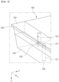
FIG. 2 is an exploded perspective view illustrating a die coater according to one embodiment of the present disclosure,FIG. 3 is an enlarged view of a portion ofFIG. 2 ,FIG. 4 is a plane view illustrating a die coater looking through the first block, andFIG. 5 is an enlarged front view illustrating part A ofFIG. 4 . - Referring to
FIG. 2 , the overall configuration of adie coater 10 according to an embodiment of the present disclosure will be described. - As described above, embodiments of the present disclosure relate to a
die coater 10 capable of effectively and simultaneously coating two different types of liquids on a current collector for a secondary battery. The two different types of liquid may be, for example, an electrode slurry and an insulating liquid. - The
die coater 10 of embodiments of the present disclosure includes afirst block 100 and asecond block 200, and ashim assembly 300 interposed therebetween. In particular, theshim assembly 300 in an embodiment of the present disclosure includes abody shim 310 and one or two or more sub shims 320. - In one embodiment, the
sub shim 320 may be configured for coupling to and detachable from thebody shim 310. In another embodiment, thesub shim 320 and thebody shim 310 may be integrally formed. - The
first block 100 is a portion comprising approximately half of the body of thedie coater 10, which comprises an insulatingliquid inlet 120. Thesecond block 200 is the portion occupying the other half of the body coupling to thefirst block 100, and in some embodiments, thesecond block 200 may comprise a manifold 210 for accommodating an electrode slurry. AlthoughFIG. 2 illustrates an embodiment in which themanifold 210 is provided in thesecond block 200, the manifold 210 may be formed in thefirst block 100; in other words, themanifold 210 for accommodating the electrode slurry may be provided in any one of thefirst block 100 and thesecond block 200. - For reference,
FIG. 2 illustrates anelectrode slurry inlet 110 in connected to themanifold 210 of thesecond block 200 formed in thefirst block 100, although theelectrode slurry inlet 110 may also be formed in thesecond block 200. On the other hand, the insulatingliquid inlet 120 has to be formed only in thefirst block 100, because the layout design is limited by theflow path 322 formed in thesub shim 320 and the airtight structure, which will be described later. - Referring to
FIG. 2 andFIG. 3 , thefirst block 100 includes a fixingportion 140 and alip block 150, wherein thelip block 150 is configured for coupling to and detachable from the fixingportion 140. Thelip block 150 includes alip 160 as a front end portion of thefirst block 100. Thelip 160 serves to generate shear between the front end of thedie coater 10 and the backup roll (not shown), thereby smoothing the electrode slurry and insulating liquid. - The fixing
portion 140 has a fixingflow path 121 that serves as a transfer path for the insulating liquid flowed in through the insulatingliquid inlet 120. The fixingflow path 121 is formed in the inside of the fixingportion 140 and has a hollow internal space suitable for the insulating liquid to be transferred. The fixingflow path 121 extends in a direction (X direction) from the upper portion of the die coater to the lower portion of the die coater. One end of the fixingflow path 121 is connected with the insulatingliquid inlet 120, and the other end of the fixingflow path 121 is connected with the first insulatingliquid flow path 151. - The
lip block 150, which is configured for coupling to and detachable from the fixingportion 140, also has insulating liquid flow paths 151,152 that serve as transfer paths for the insulating liquid. The insulating liquid flow paths 151,152 are formed in the inside of thelip block 150 and have a hollow internal space suitable for the insulating liquid to be transferred. The insulating liquid flow paths 151,152 are connected to the fixingflow path 121. Thus, the insulating liquid flowed in through the insulatingliquid inlet 120 of thefirst block 100 is discharged sequentially through the fixingflow path 121 of the fixingportion 140 and the insulating liquid flow path 151,152 of thelip block 150, and finally discharged through thesecond slit 328. - The
lip block 150 comprising thefirst block 100 may be provided with several types of lip blocks 150 having paired insulating liquid flow paths formed according to the position of thesecond slit 328 through which the insulating liquid is discharged. When the coating pattern of the electrode is changed, it is general that the portion where the insulating liquid is applied changes its position along the width direction. Accordingly, thesecond slit 328 of thedie coater 10 changes the position along the width direction (Y direction) of thedie coater 10. Meanwhile, since the insulatingliquid inlet 120 and the fixingflow path 121 of thefirst block 100 are fixed, an inside of thelip block 150 according to an embodiment of the present disclosure is provided with alip block 150 having an insulating liquid flow path in which the one side end is connected with the fixingflow path 121 and the other side end is connected with thesecond slit 328, and several kinds of lip blocks having a paired insulating liquid flow path for each of the positions of the second slit are provided. - Accordingly, when the position of the
second slit 328, which the insulating liquid is discharged, is changed due to a change in the coating pattern of the insulating liquid, the operator can select alip block 150 that is paired with the second slit that has changed position among the several kinds of lip blocks 150, and correspond to the change in the coating pattern of the insulating liquid by replacing thelip block 150. - The insulating liquid flow paths provided in the
lip block 150 include a first insulatingliquid flow path 151 and a second insulatingliquid flow path 152. One end of the first insulatingliquid flow path 151 is connected with the fixingflow path 121 provided in the fixingportion 140 to flow in the insulating liquid flowed in the fixingflow path 121 into thelip block 150. Further, the first insulatingliquid flow path 151 extends in a direction perpendicular to the extension direction of the fixingflow path 121 in order to adapt when thesecond slit 328 changes position along the width direction (Y direction). - In one embodiment, the
lip block 150 is provided in various types with different lengths in the width direction of the first insulatingliquid flow path 151. When the electrode coating pattern is changed, thesub shim 320 forming thesecond slit 328 changes the position along the width direction (Y direction) of the die coater. As explained with reference toFIGS. 2 and3 , when thesub shim 320 is moved in the direction of the outer side of thedie coater 10 along the width direction (Y direction), it becomes distant from the insulatingliquid inlet 120. According to the present disclosure, among various types of lip blocks 150, alip block 150 having the first insulatingliquid flow path 151 having a width direction length corresponding to the width direction length from the insulatingliquid inlet 120 to thesub shim 320 can be selected in response to a change in the position of the sub shim. - One end of the second insulating
liquid flow path 152 is connected with the other end of the first insulatingliquid flow path 151 and extending in a direction parallel to the fixing flow path 121 (X direction). In addition, the other end of the second insulatingliquid flow path 152 is connected with thesecond slit 328. Therefore, the insulating liquid flowed in thelip block 150 can be discharged to the outside through thesecond slit 328 via the first insulatingliquid flow path 151, the second insulatingliquid flow path 152. - The
shim assembly 300 is interposed between thefirst block 100 and thesecond block 200, wherein theshim assembly 300 is basically interposed between thefirst block 100 and thesecond block 200 to form a slit at a height suitable for discharging the electrode slurry and insulating liquid. In addition, theshim assembly 300 serves to limit the flow direction of the electrode slurry and insulating liquid flowed in or accommodated in thedie coater 10 so that it is discharged toward the slit without flowing backward, and further serves to seal the electrode slurry and insulating liquid from leaking into any part of thedie coater 10 except the slit. - Referring to
FIGS. 2 and4 to 5 , theshim assembly 300 includes abody shim 310 and asub shim 320, which form afirst slit 318 and asecond slit 328 separated from each other. Specifically, thebody shim 310 forms thefirst slit 318 for discharging an electrode slurry accommodated in themanifold 210 of thesecond block 200, and thesub shim 320 forms thesecond slit 328 for discharging an insulating liquid supplied through thefirst block 100. - Moreover, the
body shim 310 and thesub shim 320 have the same height, and they do not overlap top and bottom; thus, thebody shim 310 and thesub shim 320 are located on the same plane between thefirst block 100 and thesecond block 200. - Referring to
FIG. 2 , thebody shim 310 includes a base 312 extending along the width direction (Y direction), and afirst guide 314 and asecond guide 316 protruding and extending from both ends of thebase 312, respectively. Thefirst guide 314 and thesecond guide 316 are spaced apart from each other in the width direction (Y direction) with the manifold 210 between them, and thefirst guide 314 and thesecond guide 316 may each be disposed so as not to cover themanifold 210. Thefirst guide 314 and thesecond guide 316 may each have a rectangular shape having a uniform width along the width direction (Y direction). Abody shim 310 is coupled to thefirst block 100 and thesecond block 200. Thebody shim 310 may be coupled to thefirst block 100 and thesecond block 200 by fixing pins, fixing bolts, or both, and thebody shim 310 may be provided with coupling holes into which they may be inserted. - Referring to
FIG. 2 andFIG. 6 , thesub shim 320 is open toward thefirst block 100 and comprises aconcave flow path 322 with a bottom surface. - Here, the
body shim 310 forms afirst slit 318 in the space between the first andsecond guides concave flow path 322 having a bottom surface form asecond slit 328 in thesub shim 320. The depth of theflow path 322 is smaller than the thickness (height) of thesub shim 320, so that eventually, as shown inFIG. 5 , the height of thefirst slit 318 corresponds to the height of thebody shim 310 and the height of thesecond slit 328 is formed smaller than the height of thesub shim 320. - Moreover, since the
body shim 310 and thesub shim 320 have the same height and located on the same plane without overlapping top and bottom, the width of thefirst slit 318 is limited as much as the width of thesub shim 320. - For example, in the first embodiment illustrated in
FIG. 2 , onesidewall 324 of the pairedsub shims 320 is adhered to an inside wall of thefirst guide 314 and thesecond guide 316, respectively (SeeFIG. 4 ). Accordingly, the distance between the facing sidewalls 324' of the paired sub shims 320 (opposite sides of the adhered sidewalls) corresponds to the substantial width of thefirst slit 318; in other words, the length of the distance between the inside walls of thefirst guide 314 and thesecond guide 316 minus the width of thesub shim 320 becomes the width of thefirst slit 318. - As such, considering the structure of the
second slit 328 formed by thesub shim 320, it is blocked from the electrode slurry of thefirst slit 318 by the twosidewalls 324, 324' of thesub shim 320. Further, since the lower side of theflow path 322 is a bottom surface and the upper side is adhered to thefirst block 100, thesub shim 320 is structurally completely isolated from the electrode slurry. Thus, thedie coater 10 according to an embodiment of the present disclosure is significantly less likely to have two different kinds of liquids mixed inside. - Referring to
FIG. 2 ,FIG. 4 , andFIG. 6 , the closed end of theconcave flow path 322 formed in thesub shim 320 is connected to the insulating liquid flow path 151,152 of thelip block 150 to receive insulating liquid. Specifically, the insulating liquid supplied from the insulatingliquid inlet 120 of thefirst block 100 is supplied to theflow path 322 of thesub shim 320 by sequentially passing through the fixingflow path 121 of the fixingportion 140, the first insulatingliquid flow path 151 of thelip block 150, and the second insulatingliquid flow path 152. For reference, as shown inFIG. 2 , the number and position of the insulatingliquid inlets 120 correspond to the number and position of the sub shims 320. - In addition, the
sub shim 320 may be coupled to thefirst block 100. Thesub shim 320 may be coupled to any one of the fixingportion 140 and thelip block 150 of thefirst block 100. In the first embodiment illustrated inFIG. 2 , thesub shim 320 is coupled to thelip block 150 of thefirst block 100. Thesub shim 320 may be fixed to thefirst block 100 with apin member 130 inserted into acoupling hole 326 provided in thesub shim 320. The position of thesub shim 320 is fixed by thepin member 130. Thepin member 130 may be disposed parallel to the second insulatingliquid flow path 152 of thelip block 150 or may protrude around the fixingflow path 121 of the fixingportion 140. - Here, the
pin member 130 and thecoupling hole 326 are preferably designed such that the fixed position and direction of thesub shim 320 is uniformly determined. Specifically, thesub shim 320 should not rotate when inserted into thepin member 130 to ensure that the installation direction is uniformly determined, which may be accomplished by designing thepin member 130 in a plurality, forming thepin member 130 and thecoupling hole 326 in a shape other than a circular cross-section, or a combination of these structures. Further, if necessary, thesecond block 200 may be provided with a concavepin insertion hole 220 to accommodate the protrudingpin member 130. - The second embodiment of the present disclosure is an embodiment suitable for applying two or more rows of electrode slurry and insulating liquid, respectively, on the current collector, which is an electrode base material, and then a slitting process is performed.
- In other words, the second embodiment is an embodiment suitable for simultaneously applying active material coatings to have a structure of "insulating liquid - electrode slurry - insulating liquid" in two or more rows on the current collector.
-
FIG. 7 is an exploded perspective view illustrating a die coater according to another embodiment of the present disclosure, andFIG. 8 is a perspective view of thesub shim 330 illustrated inFIG. 7 . - Referring to these drawings, the second embodiment includes the structure of the first embodiment described above, but further includes a
second sub shim 330. Thesecond sub shim 330 is installed in the middle of the width direction of the die coater 10 (Y direction).In some embodiments, thesecond sub shim 330 discharges insulating liquid in two streams through aU-shaped flow path 332. In other words, thesecond sub shim 330 is configured to discharge insulating liquid in two streams corresponding to each of the sub shims 320 on both sides adhered and disposed to the first andsecond guides - In addition, a
second sub shim 330 is disposed between the first andsecond guides body shim 310, and in the same manner that the aforementioned sub shims 320 limit the substantial width of thefirst slit 318, thesecond sub shim 330 also functions as a limiting element of thefirst slit 318. Thus, thesecond sub shim 330, disposed in the middle of thefirst slit 318, splits the insulating liquid into two streams, thereby causing the electrode slurry to be discharged in two parallel rows. The height of thesecond sub shim 330 corresponds to the height of the sub shims 320. - According to such disposition of the
second sub shim 330 and the two-row discharge structure of the insulating liquid, the application structure of "insulating liquid - electrode slurry - insulating liquid" on the current collector is formed in two rows parallel according to the length direction of the current collector, and two current collector rolls can be obtained by performing a slitting process to cut the middle of the two parallel rows. - Referring to
FIG. 8 , thesecond sub shim 330 has the same configuration as thesub shim 320 except for the structure of theU-shaped flow path 332. Specifically, thesecond sub shim 330 has a concaveU-shaped flow path 332 that is open toward thefirst block 100 and has a bottom surface. The closed end of theU-shaped flow path 332 is connected to the insulating liquid flow path of thelip block 150, and the two open ends of theU-shaped flow path 332 form athird slit 338. Similarly, the position of thesecond sub shim 330 is fixed such that thecoupling hole 336 is engaged in thepin member 130 and does not rotate. - Here, in the second embodiment, although it is described that the electrode slurry and the insulating liquid are simultaneously applied in two rows in parallel by adding the
second sub shim 330, it can be obviously understood by those skilled in the art that two or more second sub shims 330 may be added and thus applying in three or more rows. -
FIG. 9 is a front view and perspective view of a sub shim according to one embodiment of the present disclosure, and the sub shim ofFIG. 9 will be described, with focusing on the differences from thesub shim 320 described with reference toFIG. 6 . - Referring to
FIG. 9 , thesub shim 420 comprises aflow path 422 that penetrates in the thickness direction of thesub shim 420. Compared to the embodiment illustrated inFIG. 6 , theflow path 422 is open in the direction toward the first block and is also open in the direction toward the second block. A closed end of theflow path 422 is connected to an insulatingliquid flow path 152 of thelip block 150 to receive insulating liquid, and an open end of theflow path 422 forms asecond slit 428. The depth of theflow path 422 and the height of thesecond slit 428 are each the same as the thickness of thesub shim 420. -
FIG. 10 is a front view and perspective view of a sub shim according to one embodiment of the present disclosure, and the sub shim ofFIG. 10 will be described, with focusing on the differences from thesub shim 320 described with reference toFIG. 6 . - Referring to
FIG. 10 , thesub shim 520 has aflow path 522 therein. Compared to the embodiment shown inFIG. 6 , theflow path 522 is not open in the direction toward the first block. The closed end of theflow path 522 is connected with the insulatingliquid flow path 152 of thelip block 150 to receive insulating liquid, and the open end of theflow path 522 forms asecond slit 528. A height of thesecond slit 528 is formed smaller than a thickness of thesub shim 520.[Description of Reference Numerals] 10: die coater 100: first block 200: second block 110: electrode slurry inlet 120: insulating liquid inlet 121: fixing flow path 130: pin member 140: fixing portion 150: lip block 160: lip 151: first insulating liquid flow path 152: second insulating liquid flow path 210: manifold 220: pin insertion hole 300: shim assembly 310: body shim 320, 420, 520: sub shim 312: base 314: first guide 316: second guide 318: first slit 322, 422, 522: flow path 324, 424, 524: sidewall 326, 426, 526: coupling hole 328, 428, 528: second slit 330: second sub shim 332: U-shaped flow path 334: sidewall 336: coupling hole 338: third slit
Claims (19)
- A die coater (10) comprising:a first block (100) having an insulating liquid inlet (120) and a second block (200) placed on the first block (100); anda shim assembly (300) interposed between the first block (100) and the second block (200) and configured to form a first slit (318) and a second slit (328, 428, 528) separated from each other;wherein the first block (100) comprises:a fixing portion (140) having a fixing flow path (121) therein that is a transfer path for an insulating liquid flowing in through the insulating liquid inlet (120); anda lip block (150) configured to be coupled to and detachable from the fixing portion (140) and forming a front end of the first block (100),wherein the lip block (150) has an insulating liquid flow (151, 152) path that is connected to the fixing flow path (121) and is a transfer path for the insulating liquid flowing in from the fixing flow path (121) to be discharged through the second slit (328, 428, 528).
- The die (10) coater of claim 1, wherein the insulating liquid flow path (151, 152) comprises:a first insulating liquid flow path (151), one end of which is connected to the fixing flow path (121) and extends in a direction (Y) perpendicular to an extension direction (X) of the fixing flow path (121); anda second insulating liquid flow path (152) connected to the other end of the first insulating liquid flow path (151) and extending in a direction (X) parallel to the fixing flow path (121).
- The die coater (10) of claim 1 or 2, wherein the fixing flow path (121) extends in a direction from an upper portion of the die coater (10) to a lower portion of the die coater (10).
- The die coater (10) of any one of claims 1 to 3, wherein one of the first block (100) and the second block (200) is provided with a manifold (210) receiving an electrode slurry.
- The die coater (10) of any one of claims 1 to 4, wherein the shim assembly (300) comprises a body shim (310) forming the first slit (318) for discharging an electrode slurry and a sub shim (320, 420, 520) forming the second slit (328, 428, 528) for discharging the insulating liquid.
- The die coater (10) of claim 5, wherein the body shim (310) and the sub shim (320, 420, 520) have a same height and do not overlap top and bottom to be located on a same plane between the first block (100) and the second block (200).
- The die coater (10) of claim 5 or 6, wherein a height of the first slit (318) corresponds to a height of the body shim (310), and a height of the second slit (328, 428, 528) is smaller than a height of the sub shim (320, 420, 520).
- The die coater (10) of any one of claims 5 to 7, wherein the sub shim (320, 420, 520) comprises a concave flow path (322, 422, 522) that is open toward the first block (100) and has a bottom surface.
- The die coater (10) of any one of claims 5 to 7, wherein the sub shim (320, 420, 520) comprises a flow path (322, 422, 522) that extends through the sub shim (320, 420, 520) in a thickness direction of the sub shim (320, 420, 520).
- The die coater (10) of any one of claims 5 to 7, wherein the sub shim (320, 420, 520) comprises a flow path (322, 422, 522) therein.
- The die coater (10) of any one claim of claim 8 to 10, wherein a closed end of the flow path (322, 422, 522) is connected to an insulating liquid flow path (151, 152) of the lip block (150), wherein an open end of the flow path forms the second slit (328, 428, 528).
- The die coater (10) of any one of claims 5 to 11, wherein the body shim (310) comprises:a base (312) extending along a width direction (Y); andfirst (314) and second guides (316) protruding and extending from both ends of the base (312), respectively.
- The die coater (10) of any one of claims 5 to 12, comprising two or more sub shims (320, 420, 520).
- The die coater (10) of any one of claims 5 to 13, wherein the or each sub shim (320, 402, 520) is coupled to the first block (100).
- The die coater (10) of any one of claims 5 to 14, wherein the or each sub shim (320, 420, 520) is coupled to a lip block (150) of the first block (100).
- The die coater (10) of any one of claims 5 to 15, wherein the body shim (310) is coupled to the first block (100) and the second block (200).
- The die coater (10) of any one of claims 5 to 16, wherein the body shim (320) does not cover the manifold (210).
- The die coater (10) of claim 2, wherein the lip block (150) is provided in various types with different lengths in the width direction (Y) of the first insulating liquid flow path (151).
- The die coater (10) of any one of claims 1 to 18, wherein several kinds of lip blocks (150) having paired insulating liquid flow paths (151, 152) formed according to a position of the second slit (328, 428, 528) are provided, thereby the lip blocks (150) are configured to be replaced to adapt to a change in position of the second slit (328, 428, 528).
Applications Claiming Priority (1)
| Application Number | Priority Date | Filing Date | Title |
|---|---|---|---|
| KR20230127706 | 2023-09-25 |
Publications (2)
| Publication Number | Publication Date |
|---|---|
| EP4534210A1 true EP4534210A1 (en) | 2025-04-09 |
| EP4534210B1 EP4534210B1 (en) | 2026-04-15 |
Family
ID=92895668
Family Applications (1)
| Application Number | Title | Priority Date | Filing Date |
|---|---|---|---|
| EP24201976.8A Active EP4534210B1 (en) | 2023-09-25 | 2024-09-23 | Die coater for coating electrode slurry and insulating liquid |
Country Status (3)
| Country | Link |
|---|---|
| US (1) | US20250105243A1 (en) |
| EP (1) | EP4534210B1 (en) |
| KR (1) | KR20250045481A (en) |
Families Citing this family (1)
| Publication number | Priority date | Publication date | Assignee | Title |
|---|---|---|---|---|
| CN218945476U (en) * | 2022-11-29 | 2023-05-02 | 宁德时代新能源科技股份有限公司 | Coating dies and coating equipment |
Citations (3)
| Publication number | Priority date | Publication date | Assignee | Title |
|---|---|---|---|---|
| CN207667933U (en) * | 2017-11-28 | 2018-07-31 | 青海时代新能源科技有限公司 | Apparatus for coating |
| JP7116936B1 (en) * | 2022-03-30 | 2022-08-12 | 株式会社タンガロイ | die head |
| CN218190724U (en) * | 2022-10-08 | 2023-01-03 | 宁德时代新能源科技股份有限公司 | Coating die head and coating device |
Family Cites Families (1)
| Publication number | Priority date | Publication date | Assignee | Title |
|---|---|---|---|---|
| JP7739438B2 (en) | 2021-12-08 | 2025-09-16 | エルジー エナジー ソリューション リミテッド | Slot die shim and slot die including same |
-
2024
- 2024-09-23 EP EP24201976.8A patent/EP4534210B1/en active Active
- 2024-09-24 KR KR1020240129036A patent/KR20250045481A/en active Pending
- 2024-09-24 US US18/894,737 patent/US20250105243A1/en active Pending
Patent Citations (3)
| Publication number | Priority date | Publication date | Assignee | Title |
|---|---|---|---|---|
| CN207667933U (en) * | 2017-11-28 | 2018-07-31 | 青海时代新能源科技有限公司 | Apparatus for coating |
| JP7116936B1 (en) * | 2022-03-30 | 2022-08-12 | 株式会社タンガロイ | die head |
| CN218190724U (en) * | 2022-10-08 | 2023-01-03 | 宁德时代新能源科技股份有限公司 | Coating die head and coating device |
Also Published As
| Publication number | Publication date |
|---|---|
| US20250105243A1 (en) | 2025-03-27 |
| KR20250045481A (en) | 2025-04-01 |
| EP4534210B1 (en) | 2026-04-15 |
Similar Documents
| Publication | Publication Date | Title |
|---|---|---|
| US20240024911A1 (en) | Die Coater Shim and Die Coater for Coating Active Material on Current Collector for Secondary Battery | |
| US20240058834A1 (en) | Die Coater for Coating Current Collector of Secondary Battery with Active Material | |
| US11642692B2 (en) | Coating die, coating device, coating method, and method for manufacturing secondary cell | |
| KR102656809B1 (en) | Die coater for multi-layer coating of electrode slurry | |
| US20250050372A1 (en) | Die Coater for Coating Active Material of Secondary Battery Current Collector | |
| KR20190019827A (en) | Slot Die Coater Changing Coating Formation of Electrode Active Material Slurry by Movement of Slots | |
| US20250091084A1 (en) | Die Coater for Coating Active Material of Secondary Battery Current Collector | |
| EP4534210A1 (en) | Die coater for coating electrode slurry and insulating liquid | |
| EP4410439A1 (en) | Coating die head, and coating device for battery electrode plate | |
| KR102874374B1 (en) | Slot die coater | |
| KR20200072940A (en) | Distribution plate for sofc and sofc having the same | |
| EP4663307A1 (en) | Die coater, coating equipment comprising same, and method for coating electrode using same | |
| CN121222623A (en) | Slit mold coating machine | |
| CN224087158U (en) | Coating structure, coating equipment and battery production system | |
| JP2026508470A (en) | Slot die with split manifold | |
| KR20250156306A (en) | Dual slot die coater | |
| CN117881486A (en) | Slot Die Coater |
Legal Events
| Date | Code | Title | Description |
|---|---|---|---|
| PUAI | Public reference made under article 153(3) epc to a published international application that has entered the european phase |
Free format text: ORIGINAL CODE: 0009012 |
|
| STAA | Information on the status of an ep patent application or granted ep patent |
Free format text: STATUS: REQUEST FOR EXAMINATION WAS MADE |
|
| 17P | Request for examination filed |
Effective date: 20240923 |
|
| AK | Designated contracting states |
Kind code of ref document: A1 Designated state(s): AL AT BE BG CH CY CZ DE DK EE ES FI FR GB GR HR HU IE IS IT LI LT LU LV MC ME MK MT NL NO PL PT RO RS SE SI SK SM TR |
|
| GRAP | Despatch of communication of intention to grant a patent |
Free format text: ORIGINAL CODE: EPIDOSNIGR1 |
|
| STAA | Information on the status of an ep patent application or granted ep patent |
Free format text: STATUS: GRANT OF PATENT IS INTENDED |
|
| RIC1 | Information provided on ipc code assigned before grant |
Ipc: B05C 5/02 20060101AFI20251027BHEP Ipc: B05C 9/06 20060101ALI20251027BHEP |
|
| INTG | Intention to grant announced |
Effective date: 20251106 |
|
| P01 | Opt-out of the competence of the unified patent court (upc) registered |
Free format text: CASE NUMBER: UPC_APP_0015403_4534210/2025 Effective date: 20251201 |
|
| GRAS | Grant fee paid |
Free format text: ORIGINAL CODE: EPIDOSNIGR3 |
|
| GRAA | (expected) grant |
Free format text: ORIGINAL CODE: 0009210 |
|
| STAA | Information on the status of an ep patent application or granted ep patent |
Free format text: STATUS: THE PATENT HAS BEEN GRANTED |
|
| AK | Designated contracting states |
Kind code of ref document: B1 Designated state(s): AL AT BE BG CH CY CZ DE DK EE ES FI FR GB GR HR HU IE IS IT LI LT LU LV MC ME MK MT NL NO PL PT RO RS SE SI SK SM TR |
|
| REG | Reference to a national code |
Ref country code: CH Ref legal event code: F10 Free format text: ST27 STATUS EVENT CODE: U-0-0-F10-F00 (AS PROVIDED BY THE NATIONAL OFFICE) Effective date: 20260415 |