EP4534173A1 - Mid-pressure water separation for environmental control system - Google Patents
Mid-pressure water separation for environmental control system Download PDFInfo
- Publication number
- EP4534173A1 EP4534173A1 EP24204248.9A EP24204248A EP4534173A1 EP 4534173 A1 EP4534173 A1 EP 4534173A1 EP 24204248 A EP24204248 A EP 24204248A EP 4534173 A1 EP4534173 A1 EP 4534173A1
- Authority
- EP
- European Patent Office
- Prior art keywords
- coalescing
- water separator
- flow channels
- channel
- insert
- Prior art date
- Legal status (The legal status is an assumption and is not a legal conclusion. Google has not performed a legal analysis and makes no representation as to the accuracy of the status listed.)
- Granted
Links
Images


Classifications
-
- B—PERFORMING OPERATIONS; TRANSPORTING
- B01—PHYSICAL OR CHEMICAL PROCESSES OR APPARATUS IN GENERAL
- B01D—SEPARATION
- B01D45/00—Separating dispersed particles from gases or vapours by gravity, inertia, or centrifugal forces
- B01D45/12—Separating dispersed particles from gases or vapours by gravity, inertia, or centrifugal forces by centrifugal forces
-
- B—PERFORMING OPERATIONS; TRANSPORTING
- B01—PHYSICAL OR CHEMICAL PROCESSES OR APPARATUS IN GENERAL
- B01D—SEPARATION
- B01D45/00—Separating dispersed particles from gases or vapours by gravity, inertia, or centrifugal forces
- B01D45/04—Separating dispersed particles from gases or vapours by gravity, inertia, or centrifugal forces by utilising inertia
- B01D45/08—Separating dispersed particles from gases or vapours by gravity, inertia, or centrifugal forces by utilising inertia by impingement against baffle separators
-
- B—PERFORMING OPERATIONS; TRANSPORTING
- B01—PHYSICAL OR CHEMICAL PROCESSES OR APPARATUS IN GENERAL
- B01D—SEPARATION
- B01D45/00—Separating dispersed particles from gases or vapours by gravity, inertia, or centrifugal forces
- B01D45/12—Separating dispersed particles from gases or vapours by gravity, inertia, or centrifugal forces by centrifugal forces
- B01D45/16—Separating dispersed particles from gases or vapours by gravity, inertia, or centrifugal forces by centrifugal forces generated by the winding course of the gas stream, the centrifugal forces being generated solely or partly by mechanical means, e.g. fixed swirl vanes
-
- B—PERFORMING OPERATIONS; TRANSPORTING
- B64—AIRCRAFT; AVIATION; COSMONAUTICS
- B64D—EQUIPMENT FOR FITTING IN OR TO AIRCRAFT; FLIGHT SUITS; PARACHUTES; ARRANGEMENT OR MOUNTING OF POWER PLANTS OR PROPULSION TRANSMISSIONS IN AIRCRAFT
- B64D13/00—Arrangements or adaptations of air-treatment apparatus for aircraft crew or passengers, or freight space
- B64D13/06—Arrangements or adaptations of air-treatment apparatus for aircraft crew or passengers, or freight space the air being conditioned
-
- F—MECHANICAL ENGINEERING; LIGHTING; HEATING; WEAPONS; BLASTING
- F25—REFRIGERATION OR COOLING; COMBINED HEATING AND REFRIGERATION SYSTEMS; HEAT PUMP SYSTEMS; MANUFACTURE OR STORAGE OF ICE; LIQUEFACTION SOLIDIFICATION OF GASES
- F25B—REFRIGERATION MACHINES, PLANTS OR SYSTEMS; COMBINED HEATING AND REFRIGERATION SYSTEMS; HEAT PUMP SYSTEMS
- F25B43/00—Arrangements for separating or purifying gases or liquids; Arrangements for vaporising the residuum of liquid refrigerant, e.g. by heat
-
- F—MECHANICAL ENGINEERING; LIGHTING; HEATING; WEAPONS; BLASTING
- F25—REFRIGERATION OR COOLING; COMBINED HEATING AND REFRIGERATION SYSTEMS; HEAT PUMP SYSTEMS; MANUFACTURE OR STORAGE OF ICE; LIQUEFACTION SOLIDIFICATION OF GASES
- F25B—REFRIGERATION MACHINES, PLANTS OR SYSTEMS; COMBINED HEATING AND REFRIGERATION SYSTEMS; HEAT PUMP SYSTEMS
- F25B9/00—Compression machines, plants or systems, in which the refrigerant is air or other gas of low boiling point
- F25B9/002—Compression machines, plants or systems, in which the refrigerant is air or other gas of low boiling point characterised by the refrigerant
- F25B9/004—Compression machines, plants or systems, in which the refrigerant is air or other gas of low boiling point characterised by the refrigerant the refrigerant being air
-
- F—MECHANICAL ENGINEERING; LIGHTING; HEATING; WEAPONS; BLASTING
- F25—REFRIGERATION OR COOLING; COMBINED HEATING AND REFRIGERATION SYSTEMS; HEAT PUMP SYSTEMS; MANUFACTURE OR STORAGE OF ICE; LIQUEFACTION SOLIDIFICATION OF GASES
- F25B—REFRIGERATION MACHINES, PLANTS OR SYSTEMS; COMBINED HEATING AND REFRIGERATION SYSTEMS; HEAT PUMP SYSTEMS
- F25B9/00—Compression machines, plants or systems, in which the refrigerant is air or other gas of low boiling point
- F25B9/06—Compression machines, plants or systems, in which the refrigerant is air or other gas of low boiling point using expanders
-
- B—PERFORMING OPERATIONS; TRANSPORTING
- B64—AIRCRAFT; AVIATION; COSMONAUTICS
- B64D—EQUIPMENT FOR FITTING IN OR TO AIRCRAFT; FLIGHT SUITS; PARACHUTES; ARRANGEMENT OR MOUNTING OF POWER PLANTS OR PROPULSION TRANSMISSIONS IN AIRCRAFT
- B64D13/00—Arrangements or adaptations of air-treatment apparatus for aircraft crew or passengers, or freight space
- B64D13/06—Arrangements or adaptations of air-treatment apparatus for aircraft crew or passengers, or freight space the air being conditioned
- B64D2013/0603—Environmental Control Systems
- B64D2013/0662—Environmental Control Systems with humidity control
Definitions
- an air flow is typically cooled within a heat exchanger then provided to a water collector located downstream from the heat exchanger to capture or remove any free moisture from the airflow.
- the water collector typically includes a separation device that directs the moisture present within the airflow to outer walls of the separation device and directs the free moisture towards a drain port. Often times the heat exchanger and the water collector is substantially bulky and consume large amounts of space.
- the coalescing insert has a centerline and at least one of the plurality of fluidly distinct flow channels has a spiral-like configuration about the centerline.
- the at least one of the plurality of fluidly distinct flow channels having the spiral-like configuration has an inlet end arranged at the upstream end of the coalescing insert and an outlet end arranged at the downstream end of the coalescing insert.
- a twist angle formed between the inlet end and the outlet end is greater than 90 degrees.
- a direction of twist of the spiral-like configuration about the centerline and a direction of a spin of the flow of medium provided to the water separator are the same.
- the plurality of fluidly distinct flow channels have a diamond shaped cross-section.
- a shape of a cross-section of at least one of the plurality of fluidly distinct flow channels is different than the shape of the cross-section of another of the plurality of fluidly distinct flow channels.
- the inlet duct is mechanically coupled to the coalescing channel.
- the cool, dry medium output from the water collector 34 is provided to a second turbine 36.
- the second turbine 36 is illustrated as being arranged directly downstream from the water collector 34, it should be appreciated that in other embodiments, one or more additional components may be arranged between the outlet of the water collector 34 and the second turbine 36.
- the turbine 36 is illustrated as being part of the air cycle machine 22, embodiments where the turbine 36 is separate from the air cycle machine 22 are also within the scope of the disclosure.
- the downstream end 64 of the body 60 is open and may be directly or indirectly fluidly connected to the water extractor 54.
- the water extractor 54 may be located coaxially with the longitudinal axis X.
- the downstream end 64 of the body 60 of the inlet duct 53 is fluidly, and in some embodiments mechanically, connected to an upstream end of the water extractor 54.
- a portion of the water extractor 54 such as an outer housing thereof for example, may be configured to axially overlap the downstream end 64 of the inlet duct 53.
- the exterior surface of the body 60 at the downstream end 64 may form a sidewall of the water extractor 54.
- a coalescing insert 110 may be formed or positionable within a portion of the water extractor 50, such as within the water separator 52.
- the coalescing insert 110 is positionable within the interior of the coalescing channel 70 and may extend the entire length or only a portion of the length defined between the upstream end 74 and the downstream end 76 thereof.
- the coalescing insert 110 may be permanently or removably mountable within the interior of the coalescing channel 70.
- the coalescing insert 110 may be integrally formed with the coalescing channel 70, such as via an additive manufacturing process for example.
- a minimal amount of the medium A, and in some embodiments, none of the medium A is configured to flow between the exterior surface of the coalescing insert 110 and an interior surface of the coalescing channel 70.
- embodiments where the distance between the upstream end 114 of the coalescing insert 110 and the bend axis B is greater than the distance between the bend axis B and the downstream end 116 of the coalescing insert 110 and embodiments where the distance between the upstream end 114 of the coalescing insert 110 and the bend axis B is greater than the distance between the bend axis B and the downstream end 116 of the coalescing insert 110 are also within the scope of the disclosure.
- the flow of medium A within a flow channel 120 is configured to spin or swirl about the centerline of the coalescing insert 110.
- the plurality of flow channels 120 may twist approximately 90 degrees between the upstream end 114 and the downstream end 116 of the coalescing insert 110.
- embodiments where the flow channels 120 have a twist angle greater than 90 degrees, such as up to 180 degrees, up to 270 degrees, up to 360 degrees, or more are also contemplated herein. Further, embodiments where the twist angle is greater than 0 and less than 90 degrees are also within the scope of the disclosure.
- a water separator 52 including a coalescing insert 110 arranged within a coalescing channel 70 as illustrated and described herein facilitates, and in some embodiments maximizes, the separation of water from a flow of medium A, such as an airflow for example, within a small sizing envelope.
- a flow of medium A such as an airflow for example
- the need for swirl vanes and/or a center body to impart a rotation to the flow of medium A as known in the art is eliminated.
- the overall packaging of a pack of the ECS 20 may be reduced, and the pressure drop of the medium within the water separator may be minimized.
- the water separator 52 may be particularly useful for removing water from a flow of medium A when the water is in the form or a mist or fog, such as may be received from an outlet of a turbine.
- the first turbine 24 may be configured to maintain the temperature of the medium A above freezing, whereas the second turbine 36 may be configured to achieve a necessary pressure and/or temperature of the medium to be provided to a load.
Landscapes
- Engineering & Computer Science (AREA)
- Chemical & Material Sciences (AREA)
- General Engineering & Computer Science (AREA)
- Physics & Mathematics (AREA)
- Mechanical Engineering (AREA)
- Thermal Sciences (AREA)
- Chemical Kinetics & Catalysis (AREA)
- Power Engineering (AREA)
- Analytical Chemistry (AREA)
- Health & Medical Sciences (AREA)
- General Health & Medical Sciences (AREA)
- Pulmonology (AREA)
- Aviation & Aerospace Engineering (AREA)
- Separating Particles In Gases By Inertia (AREA)
- Solid Fuels And Fuel-Associated Substances (AREA)
Abstract
Description
- Embodiments of the present disclosure relate to environmental control systems for a vehicle, and more particularly, to a water separator suitable for use in an environmental control system of an aircraft.
- In existing environmental control systems, an air flow is typically cooled within a heat exchanger then provided to a water collector located downstream from the heat exchanger to capture or remove any free moisture from the airflow. The water collector typically includes a separation device that directs the moisture present within the airflow to outer walls of the separation device and directs the free moisture towards a drain port. Often times the heat exchanger and the water collector is substantially bulky and consume large amounts of space.
- According to an embodiment, a water separator for use in an environmental control system of an aircraft includes a coalescing channel having a curved housing. The coalescing channel has a hollow interior. A coalescing insert is arranged within the hollow interior of the coalescing channel. The coalescing insert has an upstream end, a downstream end, and plurality of fluidly distinct flow channels extending between the upstream end and the downstream end such that the plurality of fluidly distinct flow channels receive a flow of medium in parallel.
- In embodiments the coalescing channel has an upstream end and a downstream end and the upstream end is oriented perpendicularly to the downstream end.
- In embodiments the coalescing insert has a centerline and at least one of the plurality of fluidly distinct flow channels has a spiral-like configuration about the centerline.
- In embodiments the at least one of the plurality of fluidly distinct flow channels having the spiral-like configuration has an inlet end arranged at the upstream end of the coalescing insert and an outlet end arranged at the downstream end of the coalescing insert. A twist angle formed between the inlet end and the outlet end is 90 degrees.
- In embodiments the at least one of the plurality of fluidly distinct flow channels having the spiral-like configuration has an inlet end arranged at the upstream end of the coalescing insert and an outlet end arranged at the downstream end of the coalescing insert. A twist angle formed between the inlet end and the outlet end is greater than 90 degrees.
- In embodiments the at least one of the plurality of fluidly distinct flow channels having the spiral-like configuration has an inlet end arranged at the upstream end of the coalescing insert and an outlet end arranged at the downstream end of the coalescing insert. A twist angle formed between the inlet end and the outlet end is equal to or greater than 180 degrees.
- In embodiments a direction of twist of the spiral-like configuration about the centerline and a direction of a spin of the flow of medium provided to the water separator are the same.
- In embodiments a direction of twist of the spiral-like configuration about the centerline and a direction of a spin of the flow of medium provided to the water separator are different.
- In embodiments the plurality of fluidly distinct flow channels have a polygonal shaped cross-section.
- In embodiments the plurality of fluidly distinct flow channels have a hexagonal shaped cross-section.
- In embodiments the plurality of fluidly distinct flow channels have a diamond shaped cross-section.
- In embodiments a shape of a cross-section of each of the plurality of fluidly distinct flow channels is identical.
- In embodiments a shape of a cross-section of at least one of the plurality of fluidly distinct flow channels is different than the shape of the cross-section of another of the plurality of fluidly distinct flow channels.
- In embodiments an interior surface of a region of at least one of the plurality of fluidly distinct flow channels is textured.
- In embodiments a surface area at the region is increased relative to the surface area at another region of the at least one of the plurality of fluidly distinct flow channels that is not textured.
- In embodiments the coalescing insert is integrally formed with the coalescing channel.
- In embodiments the coalescing insert is removably mounted within the coalescing channel.
- In embodiments an inlet duct is fluidly connected to the plurality of fluidly distinct flow channels of the coalescing insert. The inlet duct is arranged downstream from the coalescing insert relative to the flow of medium.
- In embodiments the inlet duct is mechanically coupled to the coalescing channel.
- In embodiments an inlet of the water separator is fluidly coupled directly to a turbine outlet of an air cycle machine.
- The following descriptions should not be considered limiting in any way. With reference to the accompanying drawings, like elements are numbered alike:
-
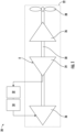
FIG. 1 is a schematic diagram of a portion of an environmental control system according to an embodiment; -
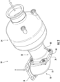
FIG. 2 is a perspective view of a water extractor according to an embodiment; -
FIG. 3 is an exploded view of the water extractor ofFIG. 2 according to an embodiment; -
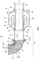
FIG. 4 is a cross-sectional view of the water extractor ofFIG. 2 according to an embodiment; -
FIG. 5 is a perspective view of a coalescing insert associated with a water separator according to an embodiment; -
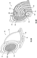
FIG. 6A is a perspective view of a coalescing channel of a water separator including a coalescing insert according to an embodiment; and -
FIG. 6B is a cross-sectional view of the coalescing channel ofFIG. 6A according to an embodiment. - A detailed description of one or more embodiments of the disclosed apparatus and method are presented herein by way of exemplification and not limitation with reference to the Figures.
- With reference now to the
FIG. 1 , an exemplary portion of anenvironmental control system 20, such as part of a pack of an environmental control system for example, is illustrated. As shown, the environmental control system (ECS) 20 includes anair cycle machine 22 having aturbine 24, and in some embodiments includes one or more other components, such as acompressor 26 and afan 28 operably coupled to theturbine 24 by arotatable shaft 30 for example. In the illustrated, non-limiting embodiment, awater separator 32 and awater collector 34 arranged in series are located downstream from, and in some embodiments directly downstream from the outlet of theturbine 24. Thewater separator 32 and thewater collector 34 in combination may also be referred to herein as a water extractor. It should be understood that embodiments where thewater separator 32 andwater collector 34 in combination are arranged downstream from any suitable component of theECS 20 are also contemplated herein. In an embodiment, thewater separator 32 is positioned within theECS 20 to receive a flow of medium, such as a fluid or air A for example, that is cool and has condensed water vapor entrained or suspended therein resulting in a fog-like consistency. - In the illustrated, non-limiting embodiment, the cool, dry medium output from the
water collector 34 is provided to asecond turbine 36. Although thesecond turbine 36 is illustrated as being arranged directly downstream from thewater collector 34, it should be appreciated that in other embodiments, one or more additional components may be arranged between the outlet of thewater collector 34 and thesecond turbine 36. Further, although theturbine 36 is illustrated as being part of theair cycle machine 22, embodiments where theturbine 36 is separate from theair cycle machine 22 are also within the scope of the disclosure. - With reference now to
FIGS. 2-4 , an example of awater extractor 50 suitable for use in anECS 20 is illustrated. As shown, thewater extractor 50 includes awater separator 52, similar towater separator 32, mechanically and fluidly coupled to awater extractor 54, similar towater collector 34. In an embodiment, thewater separator 52 and thewater extractor 54 are integrally formed, such a via an additive manufacturing process for example. However, in other embodiments, thewater separator 52 may be a separate component connected to thewater extractor 54 in any suitable manner. - As shown, the
water separator 52 includes aninlet duct 53 having a housing orbody 60 having a first, upstreamend 62 and a second,downstream end 64 relative to a flow of medium A that define a longitudinal axis X of thebody 60. In the illustrated, non-limiting embodiment, thebody 60 of theinlet duct 53 is generally cylindrical in shape and has a substantially uniform or constant inner diameter. However, it should be appreciated that embodiments where thebody 60 has another shape, such as a tapered or conical shape for example, are also contemplated herein. In an embodiment, thebody 60 has a substantially linear configuration such that theupstream end 62 and thedownstream end 64 are substantially axially aligned and such that the flow path defined between theupstream end 62 and thedownstream end 64 extends parallel to the longitudinal axis X. - The
downstream end 64 of thebody 60 is open and may be directly or indirectly fluidly connected to thewater extractor 54. Thewater extractor 54 may be located coaxially with the longitudinal axis X. In the illustrated, non-limiting embodiment, thedownstream end 64 of thebody 60 of theinlet duct 53 is fluidly, and in some embodiments mechanically, connected to an upstream end of thewater extractor 54. However, in other embodiment, a portion of thewater extractor 54, such as an outer housing thereof for example, may be configured to axially overlap thedownstream end 64 of theinlet duct 53. In such embodiments, the exterior surface of thebody 60 at thedownstream end 64 may form a sidewall of thewater extractor 54. It should be appreciated that the configuration of theinlet duct 53 illustrated and described herein is intended as an example only and that aninlet duct 53 having another suitable configuration is also within the scope of the disclosure. - With continued reference to
FIGS. 2-4 , thewater separator 52 may additionally, or alternatively, include a coalescingchannel 70. As shown, the coalescingchannel 70 includes a housing orbody 72 having a first,upstream end 74 and a second,downstream end 76 relative to the flow of medium A. In embodiments where thewater separator 52 includes both the coalescingchannel 70 and theinlet duct 53, the coalescingchannel 70 is fluidly coupled to and arranged upstream from theinlet duct 53 relative to a flow of medium A. For example, the downstream end of the coalescingchannel 70 may be fluidly connected to theupstream end 62 of thebody 60 of theinlet duct 53 as shown. In some embodiments, the coalescingchannel 70 is also mechanically coupled to theinlet duct 53 as well. For example, theinlet duct 53 may have afirst flange 66 located at theupstream end 62 thereof and the coalescingchannel 70 may have a complementarysecond flange 78 arranged at thedownstream end 76 thereof. The twoflanges channel 70 and theinlet duct 53 may be integrally formed, such as via additive manufacturing, or may be permanently connected, such as via welding for example. - In the illustrated, non-limiting embodiment, the
housing 72 of the coalescingchannel 70 is generally cylindrical in shape and has a substantially uniform or constant inner diameter. However, it should be appreciated that embodiments where thehousing 72 has another shape, are also contemplated herein. In the illustrated, non-limiting embodiment, the coalescingchannel 70 has a bent orcurved housing 72. As shown, theupstream end 74 of thehousing 72 may be oriented generally perpendicularly to thedownstream end 76 thereof. However, embodiments where thebody 72 of the coalescingchannel 70 is formed having another angle, such as an angle greater than 90 degrees or an angle less than 90 degrees are also contemplated herein. - The
water extractor 54 includes aninlet portion 80 and anoutlet portion 82. To decelerate the flow of moisture-laden medium A, anannular diffuser 84 concentrically surrounds and is attached to the inlet andoutlet portions diffuser 84 may be constructed as a single component, or alternatively, may be defined by a plurality of segments for ease of assembly. An outer section of thediffuser 84 may define a settlingchamber 86 in which the moisture within the decelerated flow of medium A falls naturally therefrom. Awall 88 extending from theinlet portion 80 of thewater extractor 54 may continuously diverge in the direction of the flow of medium A. Similarly, awall 90 may extend from theoutlet portion 82 having a flared end that is oriented against the direction of airflow. - A
guide 94 may be positioned within the gap between thewalls diffuser 84, such as by one or more webs for example. Theguide 94 defines a labyrinthine flow path causing a significant airstream deceleration within relatively short axial and radial dimensions while minimizing pressure losses as the air flows into the main body of thediffuser 84. - A
guide duct 96 is attached to theguide 94 and extends generally from theinlet portion 80 to theoutlet portion 82. The upstream end of theguide duct 96 defines anarrow scupper 98 within theinlet portion 80. Theguide duct 96 also extends downstream from theguide 94 to define anejector 100 between theoutlet wall 90 and the exterior of theguide duct 96. A portion of theguide duct 96 may be tapered inwardly in a downstream direction to accelerate the medium A through theejector 100. Awater reservoir 102 and drain 104 are provided at the bottom of thediffuser 84. The placement of the drain depends generally on the angular orientation of the reservoir to allow for gravitational drainage. It should be appreciated that the configuration of thewater extractor 54 illustrated and described herein is intended as an example only and that a water extractor having another suitable configuration is also within the scope of the disclosure. - A coalescing
insert 110 may be formed or positionable within a portion of thewater extractor 50, such as within thewater separator 52. In the illustrated, non-limiting embodiment, the coalescinginsert 110 is positionable within the interior of the coalescingchannel 70 and may extend the entire length or only a portion of the length defined between theupstream end 74 and thedownstream end 76 thereof. The coalescinginsert 110 may be permanently or removably mountable within the interior of the coalescingchannel 70. Alternatively, the coalescinginsert 110 may be integrally formed with the coalescingchannel 70, such as via an additive manufacturing process for example. - In the illustrated, non-limiting embodiment, the
body 112 of the coalescinginsert 110 has a generally circular cross-section. The size and shape defined by the outer diameter of the cross-section may be substantially constant over the length of coalescinginsert 110. However, it should be understood that the shape of the cross-section of the coalescinginsert 110 should be complementary, and in some embodiments substantially identical, to the shape of the cross-section of the interior of the coalescingchannel 70. For example, the outer diameter of the firstupstream end 114 of the coalescinginsert 110 may substantially equal to the inner diameter of the coalescingchannel 70. Accordingly, when the coalescinginsert 110 is arranged at an interior of the coalescingchannel 70, a minimal amount of the medium A, and in some embodiments, none of the medium A, is configured to flow between the exterior surface of the coalescinginsert 110 and an interior surface of the coalescingchannel 70. - With continued reference to
FIG. 4 and further reference toFIGS. 5-6B , in an embodiment, the coalescinginsert 110 includes a plurality of fluidlydistinct flow channels 120 extending between the firstupstream end 114 of the coalescinginsert 110 and a second,downstream end 116 of the coalescinginsert 110. In an embodiment, the length of each of the plurality offlow channels 120 is substantially uniform. For example, a first end of eachflow channel 120 may be arranged within the plane of theupstream end 114 and a second, opposite end of eachflow channel 120 may be arranged within a plane of thedownstream end 116. The plurality offlow channels 120 may be any suitable shape and are configured to minimize the pressure drop of the flow of medium A as it passes therethrough, increase the efficiency of the flow of medium A, or some combination thereof. In some embodiments, theflow channels 120 may have a generally rounded contour defining a circular cross-sectional configuration for example. In such embodiments, a gap may be defined betweenadjacent flow channels 120. - In other embodiments, as shown in
FIGS. 5-6B , theflow channels 120 may be formed having a generally polygonal shaped cross-sectional. In the illustrated, non-limiting embodiment, the plurality offlow channels 120 are formed with a generally hexagonal shaped cross-section. In other embodiments, the plurality offlow channels 120 may be formed with a generally rhomboid or diamond shaped cross-section. Through the use of one or more polygonal shapes, such as a hexagonal shaped cross-section for example,adjacent flow channels 120 may efficiently share walls while also providing a minimal obstruction to the flow of medium A through the coalescinginsert 110. Further, by using a polygonal shapedflow channels 120 having corners, the corners may provide pockets within which coalesced water can accumulate to form rivulets as the medium A flows through aflow channel 120. However, it should be understood that aflow channel 120 having any shape is within the scope of the disclosure. Although each of theflow channels 120 is illustrated as being substantially identical to one another, for example generally uniform in size and/or shape, in other embodiments, the size and/or shape of at least a portion of one or more of theflow channels 120 may vary from a corresponding portion of another of theflow channels 120. - Further, the size and/or shape of each
flow channel 120 may be generally constant over the length of the coalescinginsert 110 as shown, or alternatively, may vary between the firstupstream end 114 and the seconddownstream end 116 of the coalescinginsert 110. For example, one or more of theflow channels 120 may increase or decrease in size over the length of the coalescinginsert 110. In embodiments where at least one of the size and shape of aflow channel 120 varies between theupstream end 114 and thedownstream end 116 of the coalescinginsert 110, it should be understood that the variation betweenadjacent flow channels 120 may be the same or may be different. In such embodiments, any gap defined betweenadjacent flow channels 120 within the coalescinginsert 110 may also vary. - The
interior surface 122 of one or more of theflow channels 120 may be substantially smooth. In other embodiments, at least a portion of theinterior surface 122 of one or more of theflow channels 120 may be textured or roughened. Inclusion of such texture may increase the overall surface area of theinterior surface 122 of theflow channel 120 at that region relative to the surface area at another region that is not textured. - In the illustrated, non-limiting embodiment, each of the
flow channels 120 is curved about a bend axis B (seeFIG. 4 ) to form a non-linear or curved shape complementary to the coalescingchannel 70. The bend axis B may be oriented substantially perpendicular to the longitudinal axis X of thewater extractor 50. Further, the bend axis B may be arranged at a center of the coalescinginsert 110 such that a distance from the bend axis to theupstream end 114 of the coalescinginsert 110 is equal to a distance from the bend axis B to thedownstream end 116 of the coalescinginsert 110. However, embodiments where the distance between theupstream end 114 of the coalescinginsert 110 and the bend axis B is greater than the distance between the bend axis B and thedownstream end 116 of the coalescinginsert 110 and embodiments where the distance between theupstream end 114 of the coalescinginsert 110 and the bend axis B is greater than the distance between the bend axis B and thedownstream end 116 of the coalescinginsert 110 are also within the scope of the disclosure. - The coalescing
channel 70 may have a centerline C extending along a flow path of the medium A therethrough, and in some embodiments, one or more of theflow channels 120 are oriented such that theflow channel 120 extends generally parallel to this centerline C. In such embodiments, an inlet end, and an outlet end of arespective flow channel 120 oriented parallel to the centerline C are axially aligned. In other embodiments, a swirl may be imparted to the medium A within one or more of theflow channels 120 of the coalescinginsert 110. In an embodiment, as shown inFIGS. 5-6B , at least one of theflow channels 120 is configured to wrap about the centerline of the coalescinginsert 110 in a helical or spiral-like configuration. In such embodiments, the flow of medium A within aflow channel 120 is configured to spin or swirl about the centerline of the coalescinginsert 110. For example, the plurality offlow channels 120 may twist approximately 90 degrees between theupstream end 114 and thedownstream end 116 of the coalescinginsert 110. However, embodiments where theflow channels 120 have a twist angle greater than 90 degrees, such as up to 180 degrees, up to 270 degrees, up to 360 degrees, or more are also contemplated herein. Further, embodiments where the twist angle is greater than 0 and less than 90 degrees are also within the scope of the disclosure. - The direction of the twist or spiral of the at least one
flow channel 120 may be the same as the spin acting on the medium A output from theturbine 24, or alternatively, may be in opposite the direction of the spin acting on the medium output from theturbine 24. In embodiments where a plurality of theflow channels 120 have a spiral-like configuration, it should be appreciated that the circumferential distance of the spiral about the central axis X applied to flowchannels 120 may vary, such as based on the position of theflow channel 120 relative to the insert (such as close to the center vs. the outer periphery). - In operation, as the flow of medium A output from a component, such as the turbine outlet of
turbine 24 for example, passes through the plurality offlow channels 120 of the coalescinginsert 110 in parallel, moisture within the flow of medium A will coalesce in the form of droplets on theinterior surface 122 of theflow channels 120, such as within any corners of theflow channels 120. As a result, a flow of drier medium A will be arranged at the center of eachflow channel 120. During this coalescing, the flow of medium A will cause these droplets formed on theinterior surface 122 of theflow channels 120 to move through theflow channels 120, through theinlet duct 53 when included, and into thewater extractor 54 positioned directly downstream from thewater separator 52. Thewater extractor 54 may further separate a flow of medium having water entrained therein from a central drier flow of medium as is known in the art. - A
water separator 52 including a coalescinginsert 110 arranged within a coalescingchannel 70 as illustrated and described herein facilitates, and in some embodiments maximizes, the separation of water from a flow of medium A, such as an airflow for example, within a small sizing envelope. As a result, the need for swirl vanes and/or a center body to impart a rotation to the flow of medium A as known in the art is eliminated. Additionally, the overall packaging of a pack of theECS 20 may be reduced, and the pressure drop of the medium within the water separator may be minimized. Thewater separator 52 may be particularly useful for removing water from a flow of medium A when the water is in the form or a mist or fog, such as may be received from an outlet of a turbine. Further, by using thewater separator 52 in anECS pack 20 having twoturbines first turbine 24 may be configured to maintain the temperature of the medium A above freezing, whereas thesecond turbine 36 may be configured to achieve a necessary pressure and/or temperature of the medium to be provided to a load. - The term "about" is intended to include the degree of error associated with measurement of the particular quantity based upon the equipment available at the time of filing the application.
- The terminology used herein is for the purpose of describing particular embodiments only and is not intended to be limiting of the present disclosure. As used herein, the singular forms "a", "an" and "the" are intended to include the plural forms as well, unless the context clearly indicates otherwise. It will be further understood that the terms "comprises" and/or "comprising," when used in this specification, specify the presence of stated features, integers, steps, operations, elements, and/or components, but do not preclude the presence or addition of one or more other features, integers, steps, operations, element components, and/or groups thereof.
- While the present disclosure has been described with reference to an exemplary embodiment or embodiments, it will be understood by those skilled in the art that various changes may be made without departing from the scope of the invention as defined by the claims. In addition, many modifications may be made to adapt a particular situation or material to the teachings of the present disclosure without departing from the scope of the claims. Therefore, it is intended that the present disclosure not be limited to the particular embodiment disclosed, but that the present disclosure will include all embodiments falling within the scope of the claims.
Claims (14)
- A water separator for use in an environmental control system of an aircraft comprising:a coalescing channel (70) having a curved housing (72), said coalescing channel having a hollow interior; anda coalescing insert (110) arranged within the hollow interior of the coalescing channel, the coalescing insert having an upstream end (114), a downstream end (116), and plurality of fluidly distinct flow channels extending between the upstream end and the downstream end such that the plurality of fluidly distinct flow channels receive a flow of medium in parallel.
- The water separator of claim 1, wherein the coalescing channel has an upstream end (74) and a downstream end (76), the upstream end being oriented perpendicularly to the downstream end.
- The water separator of claim 1 or 2, wherein the coalescing insert has a centerline and at least one of the plurality of fluidly distinct flow channels has a spiral-like configuration about the centerline.
- The water separator of claim 3, wherein the at least one of the plurality of fluidly distinct flow channels having the spiral-like configuration has an inlet end arranged at the upstream end of the coalescing insert and an outlet end arranged at the downstream end of the coalescing insert, and a twist angle formed between the inlet end and the outlet end is 90 degrees or is greater than 90 degrees, or wherein the twist angle formed between the inlet end and the outlet end is equal to or greater than 180 degrees
- The water separator of claim 3, wherein a direction of twist of the spiral-like configuration about the centerline and a direction of a spin of the flow of medium provided to the water separator is the same, or wherein a direction of twist of the spiral-like configuration about the centerline and a direction of a spin of the flow of medium provided to the water separator is different.
- The water separator of any preceding claim, wherein the plurality of fluidly distinct flow channels have a polygonal shaped cross-section.
- The water separator of claim 6, wherein the plurality of fluidly distinct flow channels have a hexagonal shaped cross-section, or wherein the plurality of fluidly distinct flow channels have a diamond shaped cross-section.
- The water separator of any preceding claim, wherein a shape of a cross-section of each of the plurality of fluidly distinct flow channels is identical, or wherein a shape of a cross-section of at least one of the plurality of fluidly distinct flow channels is different than the shape of the cross-section of another of the plurality of fluidly distinct flow channels.
- The water separator of any preceding claim, wherein an interior surface of a region of at least one of the plurality of fluidly distinct flow channels is textured.
- The water separator of claim 9, wherein a surface area at the region is increased relative to the surface area at another region of the at least one of the plurality of fluidly distinct flow channels that is not textured.
- The water separator of any preceding claim, wherein the coalescing insert is integrally formed with the coalescing channel, or wherein the coalescing insert is removably mounted within the coalescing channel.
- The water separator of any preceding claim, further comprising an inlet duct (53) fluidly connected to the plurality of fluidly distinct flow channels of the coalescing insert, the inlet duct being arranged downstream from the coalescing insert relative to the flow of medium.
- The water separator of claim 12, wherein the inlet duct is mechanically coupled to the coalescing channel.
- The water separator of any preceding claim, wherein an inlet of the water separator is fluidly coupled directly to a turbine outlet of an air cycle machine.
Applications Claiming Priority (1)
| Application Number | Priority Date | Filing Date | Title |
|---|---|---|---|
| US18/480,176 US20250108322A1 (en) | 2023-10-03 | 2023-10-03 | Mid-pressure water separation for environmental control system |
Publications (2)
| Publication Number | Publication Date |
|---|---|
| EP4534173A1 true EP4534173A1 (en) | 2025-04-09 |
| EP4534173B1 EP4534173B1 (en) | 2026-04-15 |
Family
ID=92973559
Family Applications (1)
| Application Number | Title | Priority Date | Filing Date |
|---|---|---|---|
| EP24204248.9A Active EP4534173B1 (en) | 2023-10-03 | 2024-10-02 | Mid-pressure water separation for environmental control system |
Country Status (2)
| Country | Link |
|---|---|
| US (1) | US20250108322A1 (en) |
| EP (1) | EP4534173B1 (en) |
Citations (4)
| Publication number | Priority date | Publication date | Assignee | Title |
|---|---|---|---|---|
| JP2007229583A (en) * | 2006-02-28 | 2007-09-13 | Toshiba Corp | Moisture separator and separation method thereof |
| CN106287087A (en) * | 2016-08-15 | 2017-01-04 | 江苏迪威高压科技股份有限公司 | A kind of high pressure elbow |
| EP3467392A1 (en) * | 2017-10-09 | 2019-04-10 | Honeywell International Inc. | Improved high pressure water extraction device with shave off edge that feeds a low pressure chamber and internal helix feature to improve water collection and drainage |
| EP4427831A1 (en) * | 2023-03-07 | 2024-09-11 | Hamilton Sundstrand Corporation | Low solidity coalescing tube bundle elbow |
-
2023
- 2023-10-03 US US18/480,176 patent/US20250108322A1/en active Pending
-
2024
- 2024-10-02 EP EP24204248.9A patent/EP4534173B1/en active Active
Patent Citations (4)
| Publication number | Priority date | Publication date | Assignee | Title |
|---|---|---|---|---|
| JP2007229583A (en) * | 2006-02-28 | 2007-09-13 | Toshiba Corp | Moisture separator and separation method thereof |
| CN106287087A (en) * | 2016-08-15 | 2017-01-04 | 江苏迪威高压科技股份有限公司 | A kind of high pressure elbow |
| EP3467392A1 (en) * | 2017-10-09 | 2019-04-10 | Honeywell International Inc. | Improved high pressure water extraction device with shave off edge that feeds a low pressure chamber and internal helix feature to improve water collection and drainage |
| EP4427831A1 (en) * | 2023-03-07 | 2024-09-11 | Hamilton Sundstrand Corporation | Low solidity coalescing tube bundle elbow |
Also Published As
| Publication number | Publication date |
|---|---|
| US20250108322A1 (en) | 2025-04-03 |
| EP4534173B1 (en) | 2026-04-15 |
Similar Documents
| Publication | Publication Date | Title |
|---|---|---|
| EP4316988B1 (en) | Mid-pressure water separation for environmental control system | |
| US10526090B2 (en) | Tangential entry water separator for aircraft ECS | |
| EP3427812B1 (en) | Water extractor for environmental control system of an aircraft | |
| US20240359800A1 (en) | Centrifugal water collector with conical water scupper | |
| US12115479B2 (en) | High-pressure annular water collector with axial swirl vanes for an air cycle environmental control system | |
| US20240418421A1 (en) | Separator device, compressor with a separator device, and refrigeration system with a separator device | |
| US7591869B2 (en) | Apparatus and method for extracting condensate | |
| EP4201814A1 (en) | Multistage swirler for environmental control system | |
| EP3620222B1 (en) | High pressure water collector with radial diffuser | |
| EP4427831A1 (en) | Low solidity coalescing tube bundle elbow | |
| EP4534173B1 (en) | Mid-pressure water separation for environmental control system | |
| US5800582A (en) | Compact water collector | |
| EP4596080A1 (en) | Mid-pressure water separation for environmental control system | |
| EP4588548A1 (en) | Mid-pressure water separation for environmental control system | |
| EP4596081A1 (en) | Mid-pressure water separation for environmental control system | |
| US20260054206A1 (en) | Radial flow mid-pressure water separation for environmental control system | |
| EP4268928B1 (en) | Mid-pressure water collector (mpwc) with helical flow channel and radial scuppers | |
| EP4699935A1 (en) | Rotating fog harp coalescer | |
| CN106401977A (en) | Compressor exhaust pipe and compressor | |
| SU183357A1 (en) | Moisture separator |
Legal Events
| Date | Code | Title | Description |
|---|---|---|---|
| PUAI | Public reference made under article 153(3) epc to a published international application that has entered the european phase |
Free format text: ORIGINAL CODE: 0009012 |
|
| STAA | Information on the status of an ep patent application or granted ep patent |
Free format text: STATUS: THE APPLICATION HAS BEEN PUBLISHED |
|
| AK | Designated contracting states |
Kind code of ref document: A1 Designated state(s): AL AT BE BG CH CY CZ DE DK EE ES FI FR GB GR HR HU IE IS IT LI LT LU LV MC ME MK MT NL NO PL PT RO RS SE SI SK SM TR |
|
| STAA | Information on the status of an ep patent application or granted ep patent |
Free format text: STATUS: REQUEST FOR EXAMINATION WAS MADE |
|
| 17P | Request for examination filed |
Effective date: 20251009 |
|
| GRAP | Despatch of communication of intention to grant a patent |
Free format text: ORIGINAL CODE: EPIDOSNIGR1 |
|
| STAA | Information on the status of an ep patent application or granted ep patent |
Free format text: STATUS: GRANT OF PATENT IS INTENDED |
|
| RIC1 | Information provided on ipc code assigned before grant |
Ipc: B01D 45/12 20060101AFI20251208BHEP Ipc: B01D 45/16 20060101ALI20251208BHEP Ipc: B64D 13/00 20060101ALI20251208BHEP Ipc: F28F 1/04 20060101ALI20251208BHEP |
|
| INTG | Intention to grant announced |
Effective date: 20251219 |
|
| GRAS | Grant fee paid |
Free format text: ORIGINAL CODE: EPIDOSNIGR3 |
|
| GRAA | (expected) grant |
Free format text: ORIGINAL CODE: 0009210 |
|
| STAA | Information on the status of an ep patent application or granted ep patent |
Free format text: STATUS: THE PATENT HAS BEEN GRANTED |
|
| AK | Designated contracting states |
Kind code of ref document: B1 Designated state(s): AL AT BE BG CH CY CZ DE DK EE ES FI FR GB GR HR HU IE IS IT LI LT LU LV MC ME MK MT NL NO PL PT RO RS SE SI SK SM TR |
|
| REG | Reference to a national code |
Ref country code: CH Ref legal event code: F10 Free format text: ST27 STATUS EVENT CODE: U-0-0-F10-F00 (AS PROVIDED BY THE NATIONAL OFFICE) Effective date: 20260415 |
|
| REG | Reference to a national code |
Ref country code: DE Ref legal event code: R096 Ref document number: 602024003970 Country of ref document: DE |