EP4534128A1 - Airflow device comprising air flow path and acoustic absorber - Google Patents
Airflow device comprising air flow path and acoustic absorber Download PDFInfo
- Publication number
- EP4534128A1 EP4534128A1 EP24204411.3A EP24204411A EP4534128A1 EP 4534128 A1 EP4534128 A1 EP 4534128A1 EP 24204411 A EP24204411 A EP 24204411A EP 4534128 A1 EP4534128 A1 EP 4534128A1
- Authority
- EP
- European Patent Office
- Prior art keywords
- acoustic absorber
- flow path
- transparent layer
- acoustically transparent
- air
- Prior art date
- Legal status (The legal status is an assumption and is not a legal conclusion. Google has not performed a legal analysis and makes no representation as to the accuracy of the status listed.)
- Pending
Links
Images

Classifications
-
- A—HUMAN NECESSITIES
- A61—MEDICAL OR VETERINARY SCIENCE; HYGIENE
- A61M—DEVICES FOR INTRODUCING MEDIA INTO, OR ONTO, THE BODY; DEVICES FOR TRANSDUCING BODY MEDIA OR FOR TAKING MEDIA FROM THE BODY; DEVICES FOR PRODUCING OR ENDING SLEEP OR STUPOR
- A61M16/00—Devices for influencing the respiratory system of patients by gas treatment, e.g. ventilators; Tracheal tubes
- A61M16/0057—Pumps therefor
- A61M16/0066—Blowers or centrifugal pumps
-
- A—HUMAN NECESSITIES
- A61—MEDICAL OR VETERINARY SCIENCE; HYGIENE
- A61M—DEVICES FOR INTRODUCING MEDIA INTO, OR ONTO, THE BODY; DEVICES FOR TRANSDUCING BODY MEDIA OR FOR TAKING MEDIA FROM THE BODY; DEVICES FOR PRODUCING OR ENDING SLEEP OR STUPOR
- A61M16/00—Devices for influencing the respiratory system of patients by gas treatment, e.g. ventilators; Tracheal tubes
- A61M16/0003—Accessories therefor, e.g. sensors, vibrators, negative pressure
-
- A—HUMAN NECESSITIES
- A61—MEDICAL OR VETERINARY SCIENCE; HYGIENE
- A61M—DEVICES FOR INTRODUCING MEDIA INTO, OR ONTO, THE BODY; DEVICES FOR TRANSDUCING BODY MEDIA OR FOR TAKING MEDIA FROM THE BODY; DEVICES FOR PRODUCING OR ENDING SLEEP OR STUPOR
- A61M2202/00—Special media to be introduced, removed or treated
- A61M2202/0007—Special media to be introduced, removed or treated introduced into the body
-
- A—HUMAN NECESSITIES
- A61—MEDICAL OR VETERINARY SCIENCE; HYGIENE
- A61M—DEVICES FOR INTRODUCING MEDIA INTO, OR ONTO, THE BODY; DEVICES FOR TRANSDUCING BODY MEDIA OR FOR TAKING MEDIA FROM THE BODY; DEVICES FOR PRODUCING OR ENDING SLEEP OR STUPOR
- A61M2202/00—Special media to be introduced, removed or treated
- A61M2202/02—Gases
-
- A—HUMAN NECESSITIES
- A61—MEDICAL OR VETERINARY SCIENCE; HYGIENE
- A61M—DEVICES FOR INTRODUCING MEDIA INTO, OR ONTO, THE BODY; DEVICES FOR TRANSDUCING BODY MEDIA OR FOR TAKING MEDIA FROM THE BODY; DEVICES FOR PRODUCING OR ENDING SLEEP OR STUPOR
- A61M2205/00—General characteristics of the apparatus
- A61M2205/02—General characteristics of the apparatus characterised by a particular materials
- A61M2205/025—Materials providing resistance against corrosion
-
- A—HUMAN NECESSITIES
- A61—MEDICAL OR VETERINARY SCIENCE; HYGIENE
- A61M—DEVICES FOR INTRODUCING MEDIA INTO, OR ONTO, THE BODY; DEVICES FOR TRANSDUCING BODY MEDIA OR FOR TAKING MEDIA FROM THE BODY; DEVICES FOR PRODUCING OR ENDING SLEEP OR STUPOR
- A61M2205/00—General characteristics of the apparatus
- A61M2205/10—General characteristics of the apparatus with powered movement mechanisms
- A61M2205/103—General characteristics of the apparatus with powered movement mechanisms rotating
-
- A—HUMAN NECESSITIES
- A61—MEDICAL OR VETERINARY SCIENCE; HYGIENE
- A61M—DEVICES FOR INTRODUCING MEDIA INTO, OR ONTO, THE BODY; DEVICES FOR TRANSDUCING BODY MEDIA OR FOR TAKING MEDIA FROM THE BODY; DEVICES FOR PRODUCING OR ENDING SLEEP OR STUPOR
- A61M2205/00—General characteristics of the apparatus
- A61M2205/33—Controlling, regulating or measuring
- A61M2205/3331—Pressure; Flow
-
- A—HUMAN NECESSITIES
- A61—MEDICAL OR VETERINARY SCIENCE; HYGIENE
- A61M—DEVICES FOR INTRODUCING MEDIA INTO, OR ONTO, THE BODY; DEVICES FOR TRANSDUCING BODY MEDIA OR FOR TAKING MEDIA FROM THE BODY; DEVICES FOR PRODUCING OR ENDING SLEEP OR STUPOR
- A61M2205/00—General characteristics of the apparatus
- A61M2205/42—Reducing noise
-
- A—HUMAN NECESSITIES
- A61—MEDICAL OR VETERINARY SCIENCE; HYGIENE
- A61M—DEVICES FOR INTRODUCING MEDIA INTO, OR ONTO, THE BODY; DEVICES FOR TRANSDUCING BODY MEDIA OR FOR TAKING MEDIA FROM THE BODY; DEVICES FOR PRODUCING OR ENDING SLEEP OR STUPOR
- A61M2205/00—General characteristics of the apparatus
- A61M2205/75—General characteristics of the apparatus with filters
Definitions
- acoustically transparent layer is a term of the art, and refers to a layer that permits sound transfer therethrough.
- Implicit in the defining of the compartment by attachment of the acoustically transparent layer to the housing is that the acoustically transparent layer is sealingly attached to the housing.
- the polymer film may be apertureless.
- the acoustically transparent layer comprises a polyethylene film and/or a polyimide film.
- the acoustic absorber may have a pitted external surface, for example with at least part of the pitted external surface facing the interior surface of the acoustically transparent layer.
- a method of manufacturing a respiratory support device comprising: arranging an acoustic absorber along at least part of a flow path defined in the device for delivery of air towards a user of the manufactured device, cavities being defined in material of the acoustic absorber for absorbing sound; and arranging an acoustically transparent layer so that the acoustically transparent layer is able to separate the acoustic absorber from air in the flow path, the acoustically transparent layer being configured to permit sound in the flow path to be transmitted through the acoustically transparent layer to the acoustic absorber to enable the acoustic absorber to absorb the sound, the acoustically transparent layer having an exterior surface for exposing to the air in the flow path, and an interior surface for facing away from the flow path and towards the acoustic absorber.
- the method comprises using the acoustically transparent layer to seal off the acoustic absorber from the air in the flow path.
- the cavities defined in the material of the acoustic absorber 104 may mean that the acoustic absorber 104 has a pitted external surface, in other words an external surface provided with holes and/or recesses.
- the acoustically transparent layer 106 may assist to alleviate contamination of the holes and/or recesses of the pitted external surface of the acoustic absorber 104 during use of the airflow device 100.
- Attachment of the acoustically transparent layer 106 to the housing 108 to define the compartment 110 for receiving the acoustic absorber 104 may assist to minimize the risk of contamination of the acoustic absorber 104 whilst providing a relatively straightforwardly implementable way of mounting the acoustic absorber 104 and the acoustically transparent layer 106 in the airflow device 100.
- Implicit in the defining of the compartment 110 by attachment of the acoustically transparent layer 106 to the housing 108 is that the acoustically transparent layer 106 is sealingly attached to the housing 108.
- Such sealing attachment may be implemented in any suitable manner, for example by forming the acoustically transparent layer 106 on the housing 108 in a molding process, welding the acoustically transparent layer 106 and the housing 108 to each other, and/or using an adhesive to adhere the acoustically transparent layer 106 and the housing 108 to each other.
- the airflow device 100 comprises a filter unit in which one or more air filters 116 is or are mountable.
- a filter unit may, for example, be arranged at the air inlet 112. This may enable the air filter(s) 116, in other words inlet air filter(s) 116, to filter the ambient air upstream of the acoustically transparent layer 106. Operating lifetime of the acoustically transparent layer 106 may be prolonged, since the acoustically transparent layer 106 may be less prone to being contaminated by ambient air received in the flow path 102.
Landscapes
- Health & Medical Sciences (AREA)
- Emergency Medicine (AREA)
- Pulmonology (AREA)
- Engineering & Computer Science (AREA)
- Anesthesiology (AREA)
- Biomedical Technology (AREA)
- Heart & Thoracic Surgery (AREA)
- Hematology (AREA)
- Life Sciences & Earth Sciences (AREA)
- Animal Behavior & Ethology (AREA)
- General Health & Medical Sciences (AREA)
- Public Health (AREA)
- Veterinary Medicine (AREA)
- Duct Arrangements (AREA)
- Soundproofing, Sound Blocking, And Sound Damping (AREA)
Abstract
Description
- The present invention relates to an airflow device, in particular a respiratory support device, that includes an acoustic absorber for absorbing sound generated by the device. The invention further relates to a method for manufacturing such a device.
- Airflow devices, such as respiratory support devices, may generate sound during operation. This sound can disturb user(s) of such devices. Sound disturbance can be particularly problematic in the case of respiratory support devices, such as continuous positive airway pressure (CPAP) devices, because of the risk of the user, in other words patient or subject, being unable to sleep due to the sound generated by such devices. This is particularly undesirable when the respiratory support device is being used to treat sleep apnea.
- For this reason, acoustic absorption may be implemented in airflow devices, such as CPAP devices, in various ways. For example, foam may be used to absorb sound.
- Various challenges nonetheless remain in terms of enhancing and facilitating acoustic absorption in airflow devices, and in particular in respiratory support devices.
- US patent application
US 2012/157794 A1 discloses an airflow system in which a laminar flow is maintained by a foam housing.PCT application WO 2008/131202 A1 discloses a silencer for a CPAP device. The silencer includes a combination of reactive components, resonators and dissipative elements.PCT application WO 2021/135615 A1 discloses a noise reduction structure for a ventilation treatment device. - The invention is defined by the claims.
- According to examples in accordance with an aspect of the invention, there is provided a respiratory support device comprising: a flow path along which air is deliverable towards a user of the respiratory support device; an acoustic absorber arranged along at least part of the flow path, cavities being defined in material of the acoustic absorber for absorbing sound; an acoustically transparent layer between the flow path and the acoustic absorber, the acoustically transparent layer being configured to permit sound in the flow path to be transmitted through the acoustically transparent layer to the acoustic absorber to enable the acoustic absorber to absorb the sound, the acoustically transparent layer having an exterior surface for exposing to the air in the flow path, and an interior surface facing away from the flow path and towards the acoustic absorber; and a housing, wherein the acoustically transparent layer is attached to the housing to define a compartment that is sealed off from the air in the flow path, the acoustic absorber being arranged in the compartment.
- By arranging the acoustic absorber along at least part of the respiratory support device's flow path, the acoustic absorber can assist to minimize sound being carried along the flow path to the exterior of the respiratory support device.
- To this end, cavities are defined in the material of the acoustic absorber to absorb sound. It is noted that some manufacturers of materials for acoustic absorbers label such materials with "pores per inch PPI" as a measure for the number of cavities.
- The acoustic absorber may generally be regarded as a sink for soundwaves, which converts sound energy into thermal energy.
- Thus, the acoustic absorber can help to minimize the risk of the user of the respiratory support device being disturbed, e.g. woken up, by sound emanating from inside the respiratory support device.
- The present invention is partly based on the insight that one or more aspects of performance of a respiratory support device can be enhanced by arranging an acoustically transparent layer between the acoustic absorber and the flow path.
- By the acoustically transparent layer being between the acoustic absorber and the flow path, the acoustically transparent layer may assist to minimize or prevent collection of contaminants in and/or on the material of the acoustic absorber that may otherwise accumulate in the cavities of the acoustic absorber and reduce effectiveness of the acoustic absorber during use of the respiratory support device.
- Even though the respiratory support device may include an inlet filter, some particles may pass through the inlet filter during use and may risk accumulating in the cavities of the acoustic absorber. Also, some users may remove the inlet filter and use the respiratory support device without the inlet filter. For example, the user may forget to replace the inlet filter after cleaning the inlet filter, or the inlet filter may be damaged without the user noticing. In such scenarios, the risk of contaminants accumulating in the cavities of the acoustic absorber and reducing the effectiveness of the acoustic absorber may be lessened by inclusion of the acoustically transparent layer.
- It is noted that the term "acoustically transparent layer" is a term of the art, and refers to a layer that permits sound transfer therethrough.
- It is also noted that the term "sound energy", "sound" and "acoustic" as used herein may refer to vibrations that can heard by human beings. Thus, these terms may refer to waves that have frequencies lying between 20 Hz and 20 kHz.
- The acoustically transparent layer is arranged to seal off the acoustic absorber from the air in the flow path. Such sealing off of the acoustic absorber from the air in the flow path may mean that fluid communication, if any, between the flow path and the acoustic absorber is through the acoustically transparent layer.
- In this manner, air in the flow path may be prevented from directly contacting the acoustic absorber, with concomitant lessening of the risk of contamination of the acoustic absorber by contaminants in the air.
- The respiratory support device comprises a housing to which the acoustically transparent layer is attached to define a compartment that is sealed off from the air in the flow path, with the acoustic absorber being arranged in the compartment.
- The housing defines the compartment. The acoustic absorber is arranged in the compartment. The acoustically transparent layer closes the compartment and thereby sealing off the compartment from the air in the flow path. The housing comprises, for example, an exterior surface of the respiratory support device. The housing supports, for example, a blower unit for displacing the air along the flow path towards the user. The housing comprises, for example, a first portion and a second portion. The first portion and the second portion are connectable to each other. The acoustically transparent layer is attached to the first portion to define the compartment, wherein the second portion provides the flow path.
- Such attachment of the acoustically transparent layer to the housing to define the compartment for receiving the acoustic absorber may assist to minimize the risk of contamination of the acoustic absorber whilst providing a relatively easy implementable way of mounting the acoustic absorber and the acoustically transparent layer in the respiratory support device.
- Implicit in the defining of the compartment by attachment of the acoustically transparent layer to the housing is that the acoustically transparent layer is sealingly attached to the housing.
- Such sealing attachment may be implemented in any suitable manner, for example by forming the acoustically transparent layer on the housing in a molding process, welding the acoustically transparent layer and the housing to each other, and/or using an adhesive to adhere the acoustically transparent layer and the housing to each other.
- It is noted that the housing can be formed from any suitable material. In some embodiments, the housing is formed from a thermoplastic, e.g. polypropylene.
- Alternatively or additionally, the acoustically transparent layer may be formed from a thermoplastic, e.g. polyethylene.
- The acoustically transparent layer may comprise a polymer film. Such a polymer film may provide a relatively simple and cost-effective way of providing the acoustically transparent layer.
- The polymer film may be apertureless.
- Thus, the polymer film may prevent particles in the air in the flow path from reaching the acoustic absorber through the polymer film.
- In some embodiments, the acoustically transparent layer comprises a polyethylene film and/or a polyimide film.
- The polymer film may be formed in any suitable manner. In some embodiments, the polymer film, e.g. polyimide film, is formed from a two-component epoxy.
- The acoustic absorber may have a pitted external surface, for example with at least part of the pitted external surface facing the interior surface of the acoustically transparent layer.
- The term "pitted" is intended to mean that the external surface of the acoustic absorber is provided with holes and/or recesses.
- In such embodiments, the acoustically transparent layer may assist to alleviate contamination of the holes and/or recesses of the pitted external surface. This alleviation of contamination may, in turn, lead to enhanced acoustic performance of the respiratory support device.
- In some embodiments, the acoustic absorber comprises a porous material and/or a perforate member. The perforate member may, for example, include a Helmholtz resonator. In a Helmholtz resonator, the cavities are formed by a plurality of holes defined in a substrate, with the holes facing the acoustically transparent layer.
- Air contained in the plurality of holes may oscillate in front of the acoustically transparent layer, and thereby absorb sound transmitted from the flow path via the acoustically transparent layer.
- As an alternative or in addition to the perforate member, the acoustic absorber may include a porous material, such as a foam and/or a fibrous material.
- In the case of the fibrous material, the cavities in the acoustic absorber's material may be (at least partly) defined between fibers of the fibrous material.
- The fibrous material may include fibrous mineral wool, in other words rock wool, and/or glass fiber wool.
- Such fibrous materials may provide effective sound absorption. Moreover, the acoustically transparent layer may minimize or prevent fibers from such materials entering the flow path.
- In embodiments in which foam is included in, e.g. defines, the material of the acoustic absorber, the foam can provide particularly effective sound suppression. Whilst foams can have an intrinsic odor, e.g. derived from the manner in which they are manufactured, the acoustically transparent layer may assist to minimize the risk of this odor being carried along the flow path towards the user.
- The foam can be of any suitable type and made from any suitable material capable of being formed into a foam. In some embodiments, the foam is a silicone foam.
- In some embodiments, the interior surface of the acoustically transparent layer contacts the acoustic absorber. Alternatively, a gap may be defined between the interior surface of the acoustically transparent layer and the acoustic absorber. Thus, sound in the flow path may be transmitted to the acoustic absorber via the acoustically transparent layer and by gas, e.g. air, in the gap between the acoustically transparent layer's interior surface and the acoustic absorber. Providing the gap allows the acoustic absorber to be uneven or unflat, whereas the acoustically transparent layer can be flat or straight to minimize any disturbance of movement of air along the flow path.
- The respiratory support device may include an air inlet through which ambient air is receivable into the flow path, and the blower unit for displacing the air along the flow path towards the user.
- In such embodiments, the acoustic absorber and the acoustically transparent layer may be arranged along the flow path between the air inlet and the blower unit. Thus, the acoustic absorber may absorb sound that would otherwise emanate from the air inlet, due to sound travelling in the opposite direction to flow along the flow path.
- In some embodiments, the respiratory support device comprises a filter unit in which one or more air filters is or are mountable. Such a filter unit may, for example, be arranged at the air inlet.
- This may enable the air filter(s), in other words inlet air filter(s), to filter the ambient air upstream of the acoustically transparent layer. Operating lifetime of the acoustically transparent layer may be prolonged, since the acoustically transparent layer may be less prone to being contaminated by ambient air received in the flow path.
- It is generally noted that the respiratory support device may be of any type. In some embodiments, the respiratory support device comprises a continuous positive airway pressure, CPAP, device.
- According to another aspect there is provided a method of manufacturing a respiratory support device comprising: arranging an acoustic absorber along at least part of a flow path defined in the device for delivery of air towards a user of the manufactured device, cavities being defined in material of the acoustic absorber for absorbing sound; and arranging an acoustically transparent layer so that the acoustically transparent layer is able to separate the acoustic absorber from air in the flow path, the acoustically transparent layer being configured to permit sound in the flow path to be transmitted through the acoustically transparent layer to the acoustic absorber to enable the acoustic absorber to absorb the sound, the acoustically transparent layer having an exterior surface for exposing to the air in the flow path, and an interior surface for facing away from the flow path and towards the acoustic absorber.
- In some embodiments, the method comprises using the acoustically transparent layer to seal off the acoustic absorber from the air in the flow path.
- Alternatively or additionally, the method may comprise attaching the acoustically transparent layer to a housing of the respiratory support device to define a compartment that is sealed off from the air in the flow path; the acoustic absorber being arranged in the compartment.
- These and other aspects of the invention will be apparent from and elucidated with reference to the embodiment(s) described hereinafter.
- For a better understanding of the invention, and to show more clearly how it may be carried into effect, reference will now be made, by way of example only, to the accompanying drawings, in which:
-
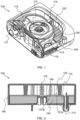
FIG. 1 provides a perspective interior view of part of an airflow device in the form of a respiratory support device; -
FIG. 2 provides a cutaway view of the device shown inFIG. 1 ; -
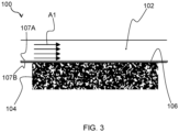
FIG. 3 provides a schematic depiction of a device according to an example; and -
FIG. 4 provides graphs of sound power vs. pressure setting for respiratory support devices having various acoustic absorption arrangements. - The invention will be described with reference to the Figures.
- It should be understood that the detailed description and specific examples, while indicating exemplary embodiments of the apparatus, systems and methods, are intended for purposes of illustration only and are not intended to limit the scope of the invention. These and other features, aspects, and advantages of the apparatus, systems and methods of the present invention will become better understood from the following description, appended claims, and accompanying drawings. It should be understood that the Figures are merely schematic and are not drawn to scale. It should also be understood that the same reference numerals are used throughout the Figures to indicate the same or similar parts.
- Provided is an airflow device, for example a respiratory support device, comprising a flow path along which air is displaceable, and an acoustic absorber arranged along at least part of the flow path. Cavities are defined in a material of the acoustic absorber for absorbing sound. The airflow device also comprises an acoustically transparent layer between the flow path and the acoustic absorber. The acoustically transparent layer is configured to transmit sound in the flow path to the acoustic absorber to enable the acoustic absorber to absorb the sound. The acoustically transparent layer has an exterior surface for exposing to the air in the flow path, and an interior surface facing away from the flow path and towards the acoustic absorber.
-
FIG. 1 provides an interior view of anairflow device 100 according to an example. In this example, theairflow device 100 is in the form of arespiratory support device 100 configured to support a user's breathing. In some embodiments, such as shown inFIG. 1 , therespiratory support device 100 comprises, e.g. is, a continuous positive airway pressure (CPAP)device 100. Such aCPAP device 100 may be employed, for example, to treat a user's sleep apnea. Alternatively or additionally, therespiratory support device 100 may comprise a bilevel positive airway pressure (BIPAP)device 100, an average volume assured pressure support (AVAPS)device 100, and/or any hospital orhome ventilator device 100. - It is noted that the principles of the present disclosure can also be applied to other types of
airflow device 100, such as air purification and/or air conditioning devices. In other words, theairflow device 100 may comprise, e.g. be, an air purification and/or air conditioning device. - The
airflow device 100 generally comprises aflow path 102 along which air is displaceable. In embodiments in which theairflow device 100 is in the form of arespiratory support device 100, air is deliverable along theflow path 102 towards the user of therespiratory support device 100. - In embodiments in which the
airflow device 100 is an air purification and/or air conditioning device, air may be displaceable along theflow path 102 towards a space being supplied with purified and/or conditioned air by the air purification and/or air conditioning device. - Referring to
FIGs. 2 and3 , theairflow device 100 comprises anacoustic absorber 104 arranged along at least part of theflow path 102. Theacoustic absorber 104 may generally be regarded as a sink for soundwaves, which converts sound energy into thermal energy. Cavities are defined in material of theacoustic absorber 104 for absorbing sound. It is noted that some manufacturers of materials for acoustic absorbers label such materials with "pores per inch PPI" as a measure for the number of cavities in the material of theacoustic absorber 104. - The cavities defined in the material of the
acoustic absorber 104 may mean that theacoustic absorber 104 has a pitted external surface, in other words an external surface provided with holes and/or recesses. - The
acoustic absorber 104 can help to minimize the risk of user(s) of theairflow device 100 being disturbed or discomforted by sound emanating from inside theairflow device 100. In embodiments in which theairflow device 100 comprises arespiratory support device 100, theacoustic absorber 104 may assist to reduce the risk of the user, e.g. a sleep apnea sufferer, being disturbed, e.g. woken up, by sound emanating from inside theairflow device 100. - The
acoustic absorber 104 can have any suitable design provided that theacoustic absorber 104 is capable of acting as a sink for soundwaves. In some embodiments, theacoustic absorber 104 comprises a porous material and/or a perforate member. The perforate member may, for example, include a Helmholtz resonator. In a Helmholtz resonator, the cavities are formed by a plurality of holes defined in a substrate, with the holes facing theflow path 102. Air contained in the plurality of holes may oscillate and thereby absorb sound transmitted from theflow path 102. - As an alternative or in addition to the perforate member, the
acoustic absorber 104 may include a porous material, such as a foam and/or a fibrous material. - In the case of the fibrous material, the cavities in the acoustic absorber's 104 material, as well as the pitted external surface of the
acoustic absorber 104, may be (at least partly) defined between fibers of the fibrous material. The fibrous material may include fibrous mineral wool, in other words rock wool, and/or glass fiber wool. Such fibrous materials may provide effective sound absorption. - In embodiments in which foam is included in, e.g. defines, the material of the
acoustic absorber 104, the foam can provide particularly effective sound suppression. The foam can be of any suitable type and made from any suitable material capable of being formed into a foam. In some embodiments, the foam is a silicone foam. - Irrespective of the particular type of
acoustic absorber 104 included in theairflow device 100, theairflow device 100 may include, in addition to theacoustic absorber 104, an acousticallytransparent layer 106 between theflow path 102 and theacoustic absorber 104. The acousticallytransparent layer 106 is configured to permit sound in theflow path 102 to be transmitted through the acousticallytransparent layer 106 to theacoustic absorber 104 to enable theacoustic absorber 104 to absorb the sound. - With continued reference to
FIGs. 2 and3 , the acousticallytransparent layer 106 has anexterior surface 107A exposed to the air in theflow path 102, and aninterior surface 107B facing away from theflow path 102 and towards theacoustic absorber 104. One or more aspects of performance of theairflow device 100 can be enhanced by arranging such an acousticallytransparent layer 106 between theacoustic absorber 104 and theflow path 102. In particular, by the acousticallytransparent layer 106 being interposed between theacoustic absorber 104 and theflow path 102, the acousticallytransparent layer 106 may assist to minimize or prevent collection of contaminants in and/or on the material of theacoustic absorber 104 that may otherwise accumulate in the cavities of theacoustic absorber 104 and reduce effectiveness of theacoustic absorber 104 during use of theairflow device 100. - For example, the acoustically
transparent layer 106 may assist to alleviate contamination of the holes and/or recesses of the pitted external surface of theacoustic absorber 104 during use of theairflow device 100. - In some embodiments, such as shown in
FIGs. 2 and3 , theinterior surface 107B of the acousticallytransparent layer 106 contacts theacoustic absorber 104. In other embodiments (not shown), a gap may be defined between theinterior surface 107B of the acousticallytransparent layer 106 and theacoustic absorber 104. Thus, sound in theflow path 102 may be transmitted to theacoustic absorber 104 via the acousticallytransparent layer 106 and by gas, e.g. air, in the gap between the acoustically transparent layer's 106interior surface 107B and theacoustic absorber 104. - In embodiments in which the
acoustic absorber 104 includes a fibrous material, such as fibrous mineral wool and/or glass fiber wool, the acousticallytransparent layer 106 may minimize or prevent fibers from such materials entering theflow path 102. In embodiments in which foam is included in, e.g. defines, the material of theacoustic absorber 104, the acousticallytransparent layer 106 may assist to minimize the risk of odor intrinsic to the foam, e.g. derived from manufacture of the foam, being carried along theflow path 102 towards the user. - The acoustically
transparent layer 106 can be formed from any suitable material and fabricated in any suitable manner provided that the acousticallytransparent layer 106 is capable of minimizing or preventing collection of contaminants in and/or on the material of theacoustic absorber 104, while permitting sound in theflow path 102 to be transmitted through the acousticallytransparent layer 106 to theacoustic absorber 104. - The acoustically
transparent layer 106 may be sufficiently thin and flexible to let soundwaves pass therethrough. - In other words, the acoustically
transparent layer 106 may be made from a thin, flexible material placed between theacoustic absorber 104, e.g. acoustically absorbing foam, and theflow path 102, e.g. apatient airway path 102 along which air is delivered to a patient when theairflow device 100 is in the form of arespiratory support device 100. - In some embodiments, the acoustically
transparent layer 106 comprises a polymer film, such as a polyethylene film or a polyimide film. Such a polymer film may provide a relatively simple and cost-effective way of providing the acousticallytransparent layer 106. - The polymer film may be apertureless. Thus, the polymer film may prevent particles in the air in the
flow path 102 from reaching theacoustic absorber 104 through the polymer film. - The polymer film, e.g. polyimide film, may, for instance, be formed from a two-component epoxy. For example, the acoustically
transparent layer 106 may be formed by covering anacoustic absorber 104, e.g. an acoustically absorbing foam, with such a two-component epoxy that cures to form the acousticallytransparent layer 106 on the external surface of theacoustic absorber 104. - In some embodiments, and as best shown in
FIG. 2 , the acousticallytransparent layer 106 is arranged to seal off theacoustic absorber 104 from the air in theflow path 102. Such sealing off of theacoustic absorber 104 from the air in theflow path 102 may mean that fluid communication, if any, between theflow path 102 and theacoustic absorber 104 is through the acousticallytransparent layer 106. In this manner, air in theflow path 102 may be prevented from directly contacting theacoustic absorber 104, with concomitant lessening of the risk of contamination of theacoustic absorber 104 by contaminants in the air. - The acoustically
transparent layer 106 preferably separates theacoustic absorber 104, e.g. foam, from theflow path 102 such that theacoustic absorber 104 is not in fluid contact with the air in theflow path 102. - The sealing off of the
acoustic absorber 104 may mean that the acousticallytransparent layer 106 provides an airtight barrier that seals theacoustic absorber 104 from contact with air in theflow path 102, e.g. the patient airstream in the case of theairflow device 100 being arespiratory support device 100. - For example, the acoustically
transparent layer 106 may provide a 100% seal, e.g. by being sealingly attached to theacoustic absorber 104 and/or to the material, e.g. housing material, that defines theflow path 102. - With continued reference to
FIG. 2 , theairflow device 100 may comprise ahousing 108 to which the acousticallytransparent layer 106 is attached to define acompartment 110 that is sealed off from the air in theflow path 102. In such embodiments, theacoustic absorber 104 may be arranged in thecompartment 110. - The
housing 108 can be formed from any suitable material. In some embodiments, thehousing 108 is formed from a thermoplastic, e.g. polypropylene. - Attachment of the acoustically
transparent layer 106 to thehousing 108 to define thecompartment 110 for receiving theacoustic absorber 104 may assist to minimize the risk of contamination of theacoustic absorber 104 whilst providing a relatively straightforwardly implementable way of mounting theacoustic absorber 104 and the acousticallytransparent layer 106 in theairflow device 100. - Implicit in the defining of the
compartment 110 by attachment of the acousticallytransparent layer 106 to thehousing 108 is that the acousticallytransparent layer 106 is sealingly attached to thehousing 108. Such sealing attachment may be implemented in any suitable manner, for example by forming the acousticallytransparent layer 106 on thehousing 108 in a molding process, welding the acousticallytransparent layer 106 and thehousing 108 to each other, and/or using an adhesive to adhere the acousticallytransparent layer 106 and thehousing 108 to each other. - Referring again to
FIG. 1 , theairflow device 100 may include anair inlet 112, e.g. anair inlet 112 delimited by thehousing 108, through which ambient air is receivable into theflow path 102. - The
airflow device 100 may also include ablower unit 114 for displacing the air along theflow path 102 towards the user or, as the case may be, towards the space to which purified and/or conditioned air is delivered by theairflow device 100. - The
acoustic absorber 104 and the acousticallytransparent layer 106 may be arranged along the flow path 102 (at least) between theair inlet 112 and theblower unit 114, for example between theair inlet 112 and ablower inlet 115 of theblower unit 114. Thus, theacoustic absorber 104 may absorb sound that would otherwise emanate from theair inlet 112, due to sound travelling in the opposite direction to the direction of flow along theflow path 102. The direction of airflow along the flow path is denoted by the arrows A1 inFIG. 3 . - In some embodiments, and referring again to
FIG. 1 , theairflow device 100 comprises a filter unit in which one ormore air filters 116 is or are mountable. Such a filter unit may, for example, be arranged at theair inlet 112. This may enable the air filter(s) 116, in other words inlet air filter(s) 116, to filter the ambient air upstream of the acousticallytransparent layer 106. Operating lifetime of the acousticallytransparent layer 106 may be prolonged, since the acousticallytransparent layer 106 may be less prone to being contaminated by ambient air received in theflow path 102. - It is generally noted that some particles may pass through the
inlet filter 116 during use and may risk accumulating in the cavities of theacoustic absorber 104. Also, some users may remove the inlet filter(s) 116 and use theairflow device 100 without the inlet filter(s) 116. For example, the user may forget to replace the inlet filter(s) 116 after cleaning the inlet filter(s) 116, or the inlet filter(s) 116 may be damaged without the user noticing. In such scenarios, the risk of contaminants accumulating in the cavities of theacoustic absorber 104 and reducing the effectiveness of theacoustic absorber 104 may be lessened by inclusion of the acousticallytransparent layer 106. - The
blower unit 114 may have any suitable design provided that theblower unit 114 is capable of displacing air along theflow path 102. Theblower unit 114 may include a motorized fan that receives air via theblower inlet 115 and forces the air downstream via ablower outlet 117. - In embodiments in which the
airflow device 100 is in the form of arespiratory support device 100, a humification unit (not visible) may be arranged downstream of theblower outlet 117. - In some embodiments, such as shown in
FIGs. 1 and 2 , theairflow device 100 comprises anairflow sensor 118 for sensing airflow in theflow path 102, e.g. between theair inlet 112 and theblower unit 114. - In embodiments in which the
air flow device 100 is arespiratory support device 100, theairflow sensor 118 may fulfil a process control and/or safety function that ensures that the requisite airflow is provided to the user to support his/her breathing. - The present disclosure also provides a method for manufacturing the
airflow device 100, e.g. the airflow device in the form of arespiratory support device 100. - The method comprises arranging an
acoustic absorber 104 along at least part of aflow path 102 defined in thedevice 100 for delivery of air. Cavities may be defined in material of theacoustic absorber 104 for absorbing sound, as previously described. - The method also comprises arranging an acoustically
transparent layer 106 so that the acousticallytransparent layer 106 is able to separate theacoustic absorber 104 from air in theflow path 102. The acousticallytransparent layer 106 permits sound in theflow path 102 to be transmitted through the acousticallytransparent layer 106 to theacoustic absorber 104 to enable theacoustic absorber 104 to absorb the sound, as also described above. - The acoustically
transparent layer 106 has anexterior surface 107A for exposing to the air in theflow path 102, and aninterior surface 107B for facing away from theflow path 102 and towards theacoustic absorber 104, e.g. towards a pitted external surface of theacoustic absorber 104. - In some embodiments, the method comprises using the acoustically
transparent layer 106 to seal off theacoustic absorber 104 from the air in theflow path 102. - The method may comprise attaching the acoustically
transparent layer 106 to ahousing 108 of theairflow device 100 to define acompartment 110 that is sealed off from the air in theflow path 102; theacoustic absorber 104 being arranged in thecompartment 110. - Use of the acoustically
transparent layer 106 was experimentally investigated by constructing aprototype airflow device 100 based on a Philips DreamStation®. Thehousing 108 of the so-called blower box of the DreamStation® was opened and the acoustically absorbing foam arranged along the DreamStation®'sflow path 102 was covered with a thin sheet of polyimide film (Kapton® from DuPont) cut in the same shape as the foam. It is noted that the acoustically absorbing foam in this non-limiting example was silicone foam. -
FIG. 4 provides graphs of sound power vs. pressure setting forrespiratory support devices 100 of the type shown inFIGs. 1 and 2 having various acoustic absorption arrangements.Graph 120 corresponds to the Philips DreamStation® without the above-described adaptation to include the acousticallytransparent layer 106.Graph 122 corresponds to the above-described prototype that includes the acousticallytransparent layer 106. Comparison ofgraphs airflow device 100 according to the present disclosure exhibiting lower noise levels relative to a comparable device that does not include the acousticallytransparent layer 106. - Without wishing to be bound by any particular theory, the acoustically
transparent layer 106 may, as well as avoiding contamination of theacoustic absorber 104, assist to reduce turbulence associated with interaction between air in theflow path 102 with the pitted external surface of theacoustic absorber 104. This alleviation of turbulence may contribute to enhanced acoustic performance of theairflow device 100. - Variations to the disclosed embodiments can be understood and effected by those skilled in the art in practicing the claimed invention, from a study of the drawings, the disclosure and the appended claims. In the claims, the word "comprising" does not exclude other elements or steps, and the indefinite article "a" or "an" does not exclude a plurality.
- The mere fact that certain measures are recited in mutually different dependent claims does not indicate that a combination of these measures cannot be used to advantage.
- If the term "adapted to" is used in the claims or description, it is noted the term "adapted to" is intended to be equivalent to the term "configured to".
- Any reference signs in the claims should not be construed as limiting the scope.
Claims (12)
- A respiratory support device (100) comprising:a flow path (102) along which air is deliverable towards a user of the respiratory support device;an acoustic absorber (104) arranged along at least part of the flow path, cavities being defined in material of the acoustic absorber for absorbing sound;an acoustically transparent layer (106) between the flow path and the acoustic absorber, the acoustically transparent layer being configured to permit sound in the flow path to be transmitted through the acoustically transparent layer to the acoustic absorber to enable the acoustic absorber to absorb the sound, the acoustically transparent layer having an exterior surface (107A) for exposing to the air in the flow path, and an interior surface (107B) facing away from the flow path and towards the acoustic absorber; anda housing (108), wherein the acoustically transparent layer (106) is attached to the housing to define a compartment (110) that is sealed off from the air in the flow path, the acoustic absorber (104) being arranged in the compartment.
- The respiratory support device (100) according to claim 1, wherein the acoustically transparent layer (106) comprises a polymer film.
- The respiratory support device (100) according to claim 1 or 2, wherein the acoustically transparent layer (106) comprises a polyethylene film and/or a polyimide film.
- The respiratory support device (100) according to any one of claims 1 to 3, wherein the acoustic absorber (104) comprises a porous material and/or a perforate member.
- The respiratory support device (100) according to any one of claims 1 to 4, wherein the acoustic absorber (104) comprises foam.
- The respiratory support device (100) according to any one of claims 1 to 5, wherein the interior surface (107B) of the acoustically transparent layer (106) contacts the acoustic absorber (104).
- The respiratory support device (100) according to any one of claims 1 to 6, wherein a gap is defined between the interior surface (107B) of the acoustically transparent layer (106) and the acoustic absorber (104).
- The respiratory support device (100) according to any one of claims 1 to 7, comprising an air inlet (112) through which ambient air is receivable into the flow path (102), and a blower unit (114) for displacing the air along the flow path towards the user.
- The respiratory support device (100) according to claim 8, wherein the acoustic absorber (104) and the acoustically transparent layer (106) are arranged along the flow path (102) between the air inlet (112) and the blower unit (114).
- The respiratory support device (100) according to any one of claims 1 to 9, comprising a filter unit in which one or more air filters (116) is or are mountable.
- The respiratory support device (100) according to any one of claims 1 to 10, comprising a continuous positive airway pressure, CPAP, device.
- A method of manufacturing a respiratory support device (100) comprising:arranging an acoustic absorber (104) along at least part of a flow path (102) defined in the device for delivery of air towards a user of the manufactured device, cavities being defined in material of the acoustic absorber for absorbing sound;arranging an acoustically transparent layer (106) so that the acoustically transparent layer is able to separate the acoustic absorber from air in the flow path, the acoustically transparent layer being configured to permit sound in the flow path to be transmitted through the acoustically transparent layer to the acoustic absorber to enable the acoustic absorber to absorb the sound, the acoustically transparent layer having an exterior surface for exposing to the air in the flow path, and an interior surface for facing away from the flow path and towards the acoustic absorber; andattaching the acoustically transparent layer to a housing of the respiratory support device (100) to define a compartment (110) that is sealed off from the air in the flow path, the acoustic absorber being arranged in the compartment.
Applications Claiming Priority (1)
| Application Number | Priority Date | Filing Date | Title |
|---|---|---|---|
| EP23202197.2A EP4534127A1 (en) | 2023-10-06 | 2023-10-06 | Airflow device comprising air flow path and acoustic absorber |
Publications (1)
| Publication Number | Publication Date |
|---|---|
| EP4534128A1 true EP4534128A1 (en) | 2025-04-09 |
Family
ID=88295849
Family Applications (2)
| Application Number | Title | Priority Date | Filing Date |
|---|---|---|---|
| EP23202197.2A Withdrawn EP4534127A1 (en) | 2023-10-06 | 2023-10-06 | Airflow device comprising air flow path and acoustic absorber |
| EP24204411.3A Pending EP4534128A1 (en) | 2023-10-06 | 2024-10-03 | Airflow device comprising air flow path and acoustic absorber |
Family Applications Before (1)
| Application Number | Title | Priority Date | Filing Date |
|---|---|---|---|
| EP23202197.2A Withdrawn EP4534127A1 (en) | 2023-10-06 | 2023-10-06 | Airflow device comprising air flow path and acoustic absorber |
Country Status (2)
| Country | Link |
|---|---|
| US (1) | US20250114546A1 (en) |
| EP (2) | EP4534127A1 (en) |
Citations (6)
| Publication number | Priority date | Publication date | Assignee | Title |
|---|---|---|---|---|
| WO2008131202A1 (en) | 2007-04-20 | 2008-10-30 | Cardinal Health 212, Llc | Acoustic attenuation chamber |
| US20120157794A1 (en) | 2010-12-20 | 2012-06-21 | Robert Goodwin | System and method for an airflow system |
| WO2013020167A1 (en) * | 2011-08-05 | 2013-02-14 | Resmed Motor Technologies Inc. | Blower |
| WO2013133889A1 (en) * | 2012-03-06 | 2013-09-12 | Resmed Motor Technologies Inc | Flow generator |
| WO2021135615A1 (en) | 2019-12-30 | 2021-07-08 | 北京怡和嘉业医疗科技股份有限公司 | Noise reduction structure for ventilation treatment device and ventilation treatment device |
| WO2023043857A1 (en) * | 2021-09-14 | 2023-03-23 | Hoffman Leslie C | Positive airway pressure device |
-
2023
- 2023-10-06 EP EP23202197.2A patent/EP4534127A1/en not_active Withdrawn
-
2024
- 2024-10-02 US US18/904,372 patent/US20250114546A1/en active Pending
- 2024-10-03 EP EP24204411.3A patent/EP4534128A1/en active Pending
Patent Citations (6)
| Publication number | Priority date | Publication date | Assignee | Title |
|---|---|---|---|---|
| WO2008131202A1 (en) | 2007-04-20 | 2008-10-30 | Cardinal Health 212, Llc | Acoustic attenuation chamber |
| US20120157794A1 (en) | 2010-12-20 | 2012-06-21 | Robert Goodwin | System and method for an airflow system |
| WO2013020167A1 (en) * | 2011-08-05 | 2013-02-14 | Resmed Motor Technologies Inc. | Blower |
| WO2013133889A1 (en) * | 2012-03-06 | 2013-09-12 | Resmed Motor Technologies Inc | Flow generator |
| WO2021135615A1 (en) | 2019-12-30 | 2021-07-08 | 北京怡和嘉业医疗科技股份有限公司 | Noise reduction structure for ventilation treatment device and ventilation treatment device |
| WO2023043857A1 (en) * | 2021-09-14 | 2023-03-23 | Hoffman Leslie C | Positive airway pressure device |
Also Published As
| Publication number | Publication date |
|---|---|
| EP4534127A1 (en) | 2025-04-09 |
| US20250114546A1 (en) | 2025-04-10 |
Similar Documents
| Publication | Publication Date | Title |
|---|---|---|
| JP7273666B2 (en) | flow generator | |
| US6216691B1 (en) | Mounting body | |
| US11690929B2 (en) | Sterilization mask with UVC reflective chamber | |
| JP6903030B2 (en) | Respiratory masks and systems | |
| CN102844091B (en) | Air filtration device | |
| EP2063945B1 (en) | Mask and flow generator system | |
| EP2968804B1 (en) | Systems for providing low-noise positive airway pressure | |
| EP4240457B1 (en) | Respiratory pressure therapy device | |
| US12023527B2 (en) | Methods and apparatus for personal protective respiratory device | |
| WO2007024955A2 (en) | Blower mounting assembly | |
| EP3363487B1 (en) | Silencer and ventilator | |
| KR20200076669A (en) | Air treatment unit for ventilation air inlets | |
| ES3007813T3 (en) | Respiratory apparatus with noise-damping member | |
| US20230302306A1 (en) | Facial guard system | |
| WO2015054867A1 (en) | Nasal filter | |
| EP4534128A1 (en) | Airflow device comprising air flow path and acoustic absorber | |
| WO1999022793A1 (en) | A muffler for an apparatus for supplying breathable gas | |
| CN219176656U (en) | Noise reduction air circuit structure and sleeping respirator | |
| CN111853944B (en) | Fresh air module and air conditioner indoor unit | |
| JP2014522473A (en) | Improved equipment for filtering and sterilizing ambient air | |
| CN216908874U (en) | Humidifier and ventilation therapy device | |
| EP4431141B1 (en) | Humidifier and ventilation treatment apparatus | |
| CN215351334U (en) | Shock attenuation structure and breathing machine | |
| JP2016020781A (en) | Electric device | |
| CN210096465U (en) | Air purifying device |
Legal Events
| Date | Code | Title | Description |
|---|---|---|---|
| PUAI | Public reference made under article 153(3) epc to a published international application that has entered the european phase |
Free format text: ORIGINAL CODE: 0009012 |
|
| STAA | Information on the status of an ep patent application or granted ep patent |
Free format text: STATUS: THE APPLICATION HAS BEEN PUBLISHED |
|
| AK | Designated contracting states |
Kind code of ref document: A1 Designated state(s): AL AT BE BG CH CY CZ DE DK EE ES FI FR GB GR HR HU IE IS IT LI LT LU LV MC ME MK MT NL NO PL PT RO RS SE SI SK SM TR |
|
| STAA | Information on the status of an ep patent application or granted ep patent |
Free format text: STATUS: REQUEST FOR EXAMINATION WAS MADE |
|
| 17P | Request for examination filed |
Effective date: 20251009 |
|
| GRAP | Despatch of communication of intention to grant a patent |
Free format text: ORIGINAL CODE: EPIDOSNIGR1 |
|
| STAA | Information on the status of an ep patent application or granted ep patent |
Free format text: STATUS: GRANT OF PATENT IS INTENDED |
|
| RIC1 | Information provided on ipc code assigned before grant |
Ipc: A61M 16/00 20060101AFI20260108BHEP |
|
| INTG | Intention to grant announced |
Effective date: 20260116 |