EP4534121A1 - Grips for injector testing systems - Google Patents
Grips for injector testing systems Download PDFInfo
- Publication number
- EP4534121A1 EP4534121A1 EP24204823.9A EP24204823A EP4534121A1 EP 4534121 A1 EP4534121 A1 EP 4534121A1 EP 24204823 A EP24204823 A EP 24204823A EP 4534121 A1 EP4534121 A1 EP 4534121A1
- Authority
- EP
- European Patent Office
- Prior art keywords
- grip
- injection needle
- injector
- interface
- profile
- Prior art date
- Legal status (The legal status is an assumption and is not a legal conclusion. Google has not performed a legal analysis and makes no representation as to the accuracy of the status listed.)
- Granted
Links
Images


Classifications
-
- G—PHYSICS
- G09—EDUCATION; CRYPTOGRAPHY; DISPLAY; ADVERTISING; SEALS
- G09B—EDUCATIONAL OR DEMONSTRATION APPLIANCES; APPLIANCES FOR TEACHING, OR COMMUNICATING WITH, THE BLIND, DEAF OR MUTE; MODELS; PLANETARIA; GLOBES; MAPS; DIAGRAMS
- G09B23/00—Models for scientific, medical, or mathematical purposes, e.g. full-sized devices for demonstration purposes
- G09B23/28—Models for scientific, medical, or mathematical purposes, e.g. full-sized devices for demonstration purposes for medicine
- G09B23/285—Models for scientific, medical, or mathematical purposes, e.g. full-sized devices for demonstration purposes for medicine for injections, endoscopy, bronchoscopy, sigmoidscopy, insertion of contraceptive devices or enemas
-
- B—PERFORMING OPERATIONS; TRANSPORTING
- B25—HAND TOOLS; PORTABLE POWER-DRIVEN TOOLS; MANIPULATORS
- B25J—MANIPULATORS; CHAMBERS PROVIDED WITH MANIPULATION DEVICES
- B25J15/00—Gripping heads and other end effectors
- B25J15/0033—Gripping heads and other end effectors with gripping surfaces having special shapes
- B25J15/0042—V-shaped gripping surfaces
-
- A—HUMAN NECESSITIES
- A61—MEDICAL OR VETERINARY SCIENCE; HYGIENE
- A61M—DEVICES FOR INTRODUCING MEDIA INTO, OR ONTO, THE BODY; DEVICES FOR TRANSDUCING BODY MEDIA OR FOR TAKING MEDIA FROM THE BODY; DEVICES FOR PRODUCING OR ENDING SLEEP OR STUPOR
- A61M5/00—Devices for bringing media into the body in a subcutaneous, intra-vascular or intramuscular way; Accessories therefor, e.g. filling or cleaning devices, arm-rests
- A61M5/14—Infusion devices, e.g. infusing by gravity; Blood infusion; Accessories therefor
- A61M5/158—Needles for infusions; Accessories therefor, e.g. for inserting infusion needles, or for holding them on the body
-
- A—HUMAN NECESSITIES
- A61—MEDICAL OR VETERINARY SCIENCE; HYGIENE
- A61M—DEVICES FOR INTRODUCING MEDIA INTO, OR ONTO, THE BODY; DEVICES FOR TRANSDUCING BODY MEDIA OR FOR TAKING MEDIA FROM THE BODY; DEVICES FOR PRODUCING OR ENDING SLEEP OR STUPOR
- A61M5/00—Devices for bringing media into the body in a subcutaneous, intra-vascular or intramuscular way; Accessories therefor, e.g. filling or cleaning devices, arm-rests
- A61M5/008—Racks for supporting syringes or needles
-
- G—PHYSICS
- G01—MEASURING; TESTING
- G01M—TESTING STATIC OR DYNAMIC BALANCE OF MACHINES OR STRUCTURES; TESTING OF STRUCTURES OR APPARATUS, NOT OTHERWISE PROVIDED FOR
- G01M99/00—Subject matter not provided for in other groups of this subclass
- G01M99/008—Subject matter not provided for in other groups of this subclass by doing functionality tests
-
- A—HUMAN NECESSITIES
- A61—MEDICAL OR VETERINARY SCIENCE; HYGIENE
- A61M—DEVICES FOR INTRODUCING MEDIA INTO, OR ONTO, THE BODY; DEVICES FOR TRANSDUCING BODY MEDIA OR FOR TAKING MEDIA FROM THE BODY; DEVICES FOR PRODUCING OR ENDING SLEEP OR STUPOR
- A61M5/00—Devices for bringing media into the body in a subcutaneous, intra-vascular or intramuscular way; Accessories therefor, e.g. filling or cleaning devices, arm-rests
- A61M5/14—Infusion devices, e.g. infusing by gravity; Blood infusion; Accessories therefor
- A61M5/158—Needles for infusions; Accessories therefor, e.g. for inserting infusion needles, or for holding them on the body
- A61M2005/1588—Needles for infusions; Accessories therefor, e.g. for inserting infusion needles, or for holding them on the body having means for monitoring, controlling or visual inspection, e.g. for patency check, avoiding extravasation
-
- A—HUMAN NECESSITIES
- A61—MEDICAL OR VETERINARY SCIENCE; HYGIENE
- A61M—DEVICES FOR INTRODUCING MEDIA INTO, OR ONTO, THE BODY; DEVICES FOR TRANSDUCING BODY MEDIA OR FOR TAKING MEDIA FROM THE BODY; DEVICES FOR PRODUCING OR ENDING SLEEP OR STUPOR
- A61M2209/00—Ancillary equipment
- A61M2209/02—Equipment for testing the apparatus
-
- A—HUMAN NECESSITIES
- A61—MEDICAL OR VETERINARY SCIENCE; HYGIENE
- A61M—DEVICES FOR INTRODUCING MEDIA INTO, OR ONTO, THE BODY; DEVICES FOR TRANSDUCING BODY MEDIA OR FOR TAKING MEDIA FROM THE BODY; DEVICES FOR PRODUCING OR ENDING SLEEP OR STUPOR
- A61M2209/00—Ancillary equipment
- A61M2209/08—Supports for equipment
- A61M2209/082—Mounting brackets, arm supports for equipment
Definitions
- This disclosure relates generally to injection device testing, and more particularly, to grips for injection testing systems.
- Injection testing systems may test one or more aspects of injection devices, including autoinjectors, for aspects such as cap removal force, plunger actuation force, injection depth, injection time, needle retraction, and/or delivered dose.
- Grips for injection testing systems are disclosed, substantially as illustrated by and described in connection with at least one of the figures, as set forth more completely in the claims.
- Injection needle testing devices that measure the dosage delivered by the injection needle, particularly by autoinjectors, include an injection needle positioner that is configured to position an injector (e.g., an autoinjector) securely and in a position suitable for various forms of testing and measurements of the injector.
- an injector e.g., an autoinjector
- Conventional injection needle testing systems are unable to easily interface with certain types of injectors due to the geometry of the injector.
- Disclosed example injection needle testing devices and injection testing systems include one or more grips and that provide excellent gripping characteristics, including supporting a range of injector geometries.
- Some example injection needle testing systems include an injection needle positioner capable of interfacing with multiple injector geometries, including symmetrical and asymmetrical geometries, with a single pair of grips.
- Disclosed example injection needle positioner include: first and second mounting brackets; a first grip, comprising: a first aperture configured to interface with the first mounting bracket; and a first grip face on a lateral side of the first grip, the first grip face comprising: a first section toward a first end of the first grip and having a first profile; and a second section toward a second end of the first grip, relative to the first section, and having a second profile different than the first profile; and a second grip, comprising: a second aperture configured to interface with the second mounting bracket; and a second grip face on a lateral side of the second grip.
- the second grip face comprises a first section toward a first end of the second grip and having a first profile and a second section toward a second end of the second grip, relative to the first section, and having a second profile different than the first profile.
- the second profile of the first grip comprises a recessed gripping groove configured to interface with an injector having an asymmetric geometry.
- the second profile of the second grip comprises a recessed gripping groove configured to interface with an injector having an asymmetric geometry.
- the first aperture extends from the first end of the first grip to the second end of the first grip, such that the aperture can interface with the first or second mounting bracket from either end of the first grip.
- the second aperture extends from a first end of the second grip to a second end of the second grip, such that the aperture can interface with the first or second mounting bracket from either end of the second grip.
- At least one of the first grip face or the second grip face comprises a slip-resistant coating.
- the slip-resistant coating is surfalloy.
- each grip lock further comprises one or more accessory mounting holes oriented parallel to the central aperture.
- the accessory mounting holes are configured to interface with one or more customization plates.
- each grip further comprises a top and bottom mounting hole oriented perpendicular to the central aperture and configured to align with the mounting openings on the mounting bracket.
- each mounting hole is threaded and configured to interface with a mounting screw.
- each grip further comprises a directional indicator configured to point in a predetermined direction when installed in a corresponding configuration.
- Disclosed example injection needle positioner include: a positioning plate having a first side configured to contact an injector having a second side opposite the first side; an injection needle positioner configured to position the injector in contact with the first side of the positioning plate, the injection needle positioner comprising: first and second mounting brackets; a first grip, comprising: a first aperture configured to interface with the first mounting bracket; and a first grip face on a lateral side of the first grip, the first grip face comprising: a first section toward a first end of the first grip and having a first profile; and a second section toward a second end of the first grip, relative to the first section, and having a second profile different than the first profile; and a second grip, comprising: a second aperture configured to interface with the second mounting bracket; and a second grip face on a lateral side of the second grip an injector actuator configured to actuate the injector to expel contents of the injector via a needle of the injector.
- FIG. 1 is an example injection testing system 100 to perform testing on injection devices, such as an autoinjector 102.
- the example injection testing system 100 may be configured, for example, to perform some or all tests to evaluate requirements of the ISO 11608-5 standard.
- the example injection testing system 100 may be, for example, a universal testing system configured for injection testing.
- the example injection testing system 100 of FIG. 1 includes positioning device(s) (e.g., to position the autoinjector 102 in one or more positions and/or orientations for automated testing), actuator(s) (e.g., to actuate components of the autoinjector 102, to actuate the positioning device(s), to position and/or orient test devices, etc.), and/or sensors to measure aspects of the autoinjector 102 during testing (e.g., load sensors to measure actuation force(s), auditory sensors to detect audible events), mass scales to measure an expelled dose, displacement and/or position sensors to trigger testing steps and/or measure displacement of components of the autoinjector 102, etc.).
- the example injection testing system 100 further includes one or more user interface devices, such as the displays 104 and input devices 106.
- FIG. 2 is a block diagram of an example injection testing system 200 including an injection needle blowoff apparatus.
- the example injection testing system 200 may be used to implement some or all of the components of the injection testing system 100 of FIG. 1 .
- the example injection testing system 200 includes an injection needle positioner 202, an injector actuator 204, an injection collector 206, and control circuitry 208.
- the injection needle positioner 202 positions and/or orients an injector 210 (e.g., an autoinjector) for one or more tests in the injection testing system 200.
- the injection needle positioner 202 may grasp the injector 210 and move and/or rotate the injector 210 for testing.
- the injection needle positioner may grasp the injector 210 through two or more grips 203.
- the injection needle positioner 202 and/or the position of the injector 210 may be measured by one or more displacement sensor(s) 212, which provides displacement and/or position information to the control circuitry 208.
- the injector actuator 204 actuates one or more aspects of the injector 210, such as a plunger or other injection mechanism of the injector 210.
- the force applied by the injector actuator 204 may by measured by a force sensor 214, which provides force measurements to the control circuitry 208.
- the injection collector 206 includes a loading surface (e.g., a positioning plate 216), blowoff nozzles 218, and a collection container 220.
- the collection container 220 and the injector 210 are positioned such that, when the injector 210 is actuated to expel fluid contained in the injector 210, the fluid is expelled into the collection container 220.
- a collection sensor 222 measures the mass and/or volume collected in the collection container 220, and provides a mass or volume measurement to the control circuitry 208.
- the positioning plate 216 allows a needle 224 of the injector 210 to extend through the positioning plate 216 toward the collection container 220.
- the positioning plate 216 may block a body of the injector 210 from extending through the positioning plate 216 using appropriately sized apertures for the needle 224 and the body of the injector 210.
- the injection needle positioner 202 may position the injector 210 to contact or abut the positioning plate 216, such that the needle 224 extends through the aperture of the positioning plate 216.
- the injector 210 may be actuated (e.g., manually, or automatically via the injector actuator 204) to expel the contents of the injector 210 into the collection container 220.
- the examples disclosed herein use the positioning plate 216 as a loading surface, other examples may use different types of loading surfaces against which the injector 210 can be actuated to expose the needle 224 and/or expel the contents of the injector 210.
- rods or other structural members which are positioned to contact a body of the injector 210 on a top side of the loading surface, and to avoid obstructing the needle 224 may be used.
- the blowoff nozzles 218 may be coupled to another surface, or otherwise adjustably supported, within the injection collector 206 adjacent the bottom side of the loading surface and/or adjacent the location the needle 224.
- the blowoff nozzles 218 are controlled to blow the last drop of fluid from at or near the tip of the needle into the collection container 220.
- a gas supply 226 provides a gas, such as nitrogen or air, to the blowoff nozzles 218.
- the gas supply 226 may be, for example, a compressed gas source, a pneumatic pump, or a blower.
- the blowoff nozzles 218 may be positioned and/or oriented to adjust a location at which the blowoff gas strikes the needle 224, and/or may be positioned and/or oriented to cause the blowoff gas to strike the needle 224 over a range of needle lengths.
- the example control circuitry 208 may be a general-purpose computer, a laptop computer, a tablet computer, and/or any other type of processing system configured to communicate with the sensors and actuators of the injection testing system 200.
- the control circuitry 208 includes a processor 228, memory 230, and a storage device 232.
- the example processor 228 may be any general purpose central processing unit (CPU) from any manufacturer.
- the processor 228 may include one or more specialized processing units, such as RISC processors with an ARM core, graphic processing units, digital signal processors, and/or system-on-chips (SoC).
- the processor 228 executes machine readable instructions 234 that may be stored locally at the processor (e.g., in an included cache or SoC), in the memory (e.g., a random access memory or other volatile memory, a read only memory or other non-volatile memory such as FLASH memory, and/or in the storage device 232.
- the example storage device 232 may be a hard drive, a solid state storage drive, a hybrid drive, a RAID array, and/or any other mass data storage device.
- FIG. 3A and 3B are perspective views of an example grip 203.
- injection needle positioner 202 may include one or more grips 203 through which injection needle positioner 202 may grasp an injector 210.
- FIG. 4A is a bottom plan view of the example grip 203 of FIGS. 3A and 3B
- FIG. 4B is a top plan view of the example grip 203 of FIGS. 3A and 3B .
- FIG. 5A is a side view of the example grip of FIGS. 3A and 3B .
- the grip 203 may include one or more apertures 302 through which the grip 203 can interface with or be coupled to the injection needle positioner 202.
- the grip 203 may include single aperture 302.
- the aperture 302 may be configured to interface with or be coupled to a mounting bracket 606 of the injection needle positioner 202.
- the aperture 302 may extend throughout a portion of the length of the grip 203 or throughout the entire length of the grip 203.
- the aperture 302 may extend from a first end 314 of the grip 203 to a second end 316 of the grip 203, such that the aperture 302 can interface with a mounting bracket 606 from either end of the grip 203.
- the size and shape of the aperture 302 may be varied.
- the aperture 302 may be square, semi-square, rectangular, circular, elliptical, or any other suitable shape.
- the example grip 203 further includes a grip face 304 on a lateral side of the grip 203.
- the example grip face 304 includes two or more sections, such as a first section 306 and a second section 308.
- the first section 306 extends from or toward a first end 314 of the grip 203
- the second section 308 extends from or toward a second end 316 of the grip 203.
- Each section 306, 308 has a profile that is configured to interface with an injector 210.
- the first section 306 and the second section 308 of the example grip 203 have different profiles to grip injectors having different profiles.
- the grip 203 may be replaced with a grip having a consistent profile (e.g., a flat face) over all or a portion of the length of the grip face.
- the profile of each section of the example grip 203 is configured to interface with an injector 210.
- the shape of the profile may be varied depending on the shape of the injector 210.
- the example grip section 308 is configured to interface with an injector 210 that has an asymmetric geometry (e.g., a specific asymmetric geometry that is incompatible with gripping by the first section 306).
- the example second section 308 includes a recessed gripping groove 310 that is configured to interface with an injector 210 that has an asymmetric geometry.
- the example recessed gripping groove 310 extends from the second end 316 of the grip 203.
- the recessed gripping groove 310 extends across at least a portion of the length of the second section 308. In other examples, the recessed gripping groove extends across the entire length of the second section 308 (e.g., extending from first end 308a to a second end 308b of the second section).
- the grip section 306 is configured to interface with an injector 210 that has a symmetric geometry.
- Example symmetric geometries of the injector 210 include cylindrical, elliptical, and semi-square geometries.
- the profile of the first section 306 of example grip 203 is defined by a v-shaped, symmetrical surface.
- the first section 306 is defined by other suitable symmetrical surface geometries, such as a semicircular geometry. While an example angle of the surface is illustrated in FIGS. 3A, 3B , and 4 , different angles may be used.
- the grip 203 is be made from a material that is uncoated. In other examples, at least a portion of grip 203 includes a slip-resistant coating.
- the slip-resistant coating of example grip 203 is configured to enhance the stability of injector 210 when engaged by two grips 203.
- Various slip-resistant coatings may be included.
- the slip-resistant coating is a surfalloy coating, rubber, brake lining materials, and/or any other appropriate coating material.
- the grip face 304 may be knurled, or otherwise textured to increase friction between the grip 203 and the injector 210 without coating.
- the grip 202, including the grip face 304 may also be bead blasted, passivated, and/or otherwise treated to improve aesthetics and/or corrosion resistance.
- the grip 203 may include one or more accessory mounting holes 312.
- the one or more accessory mounting holes 312 may be located on either end 314, 316 of the grip 203 and may be oriented parallel to the aperture 302.
- the accessory mounting holes 312 extends from a first end 314 to a second end 316 of example grip 203.
- the accessory mounting holes 312 extend from a first end 314 or from a second end 316, but only extend a portion of the length of the example grip 203.
- the accessory mounting holes 312 may be threaded and configured to interface with a threaded mounting screw.
- the accessory mounting holes 312 may be configured to interface with or couple to various accessories to either side of example grip 203.
- the accessory mounting holes 312 may be configured to interface with one or more customization plates.
- the one or more customization plates are configured to alter, customize, and/or replace the profile of the first and/or second sections 306 and 308 of the grip face 304.
- a custom plate may be attached to each of the grips 203 via the accessory mounting holes 312.
- the profile of the custom plate may be configured to engage the injector 210 prior to engagement of the injector 210 by the grips 203, which causes the custom plate to perform the gripping of the injector 210.
- the custom plates may be coated for improved grip as disclosed above.
- the shape of the profile may be configured to interface with an injector 210 having a certain geometry, such as a symmetrical or asymmetrical geometry.
- the grips 203 may include more or fewer accessory mounting holes 312 than shown in the illustrated examples.
- the grips 203 may include one or more additional alignment holes 318, which may be engaged by the custom plates and/or by an alignment obj ect (e.g., a pin) which aids in appropriate alignment of the custom plates.
- the alignment holes 318 may have one or more predetermined shapes and/or positions on the grips 203 to promote alignment and/or prevent incorrect orientation of the custom plates or other objects.
- the example grips 203 further include directional indicators 608.
- the directional indicators 608 point toward a direction in which the grips 203 close, to thereby guide an operator in properly orienting the grips 203 during installation. If the operator orients the grips 203 incorrectly, then the directional indicators 608 may point in the wrong direction.
- FIG. 6A and 6B are perspective views of an example injection needle positioner 202, including grips 203 coupled to the injection needle positioner 202 through mounting brackets 606.
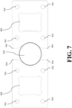
- FIG. 7 is a bottom view of the example injection needle positioner of FIG. 6 where the grips 203 are in the closed position when coupled to the mounting brackets in a first orientation.
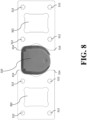
- FIG. 8 is a bottom view of the example injection needle positioner of FIG. 6 where the grips 203 are in the closed position when coupled to the mounting brackets in a second orientation.
- the example grip 203 includes one or more mounting holes 602 configured to interface with or couple to a mounting bracket 606. The mounting holes may be oriented perpendicular to the aperture 302.
- the mounting holes 602 are threaded and configured to interface with a threaded mounting screw 604 to couple to mounting bracket 606.
- one or more threaded mounting screws 604 may interface with one or more mounting openings located on the mounting bracket 606 to securely couple the grip 203 to the mounting bracket 606.
- the example injection needle positioner 202 includes two grips 203 coupled to the injection needle positioner 202 through two mounting brackets 606.
- FIG. 6A and 6B illustrate an example injection needle positioner 202 including two grips 203 oriented in an open position. When in the open position as illustrated in FIG. 6A and 6B , there is space between the grips 203 such that the grips 203 are oriented to receive an injector 210 (e.g., an autoinjector). The two grips 203 may be moved laterally towards one into a closed position as illustrated in FIG. 7 . When in the closed position as illustrated in FIG. 7 , the example grips 203 are configured to securely grip an injector 210. As illustrated in FIG. 6A, 6B , and 7 , each grip 203 of the injection needle positioner 202 may include some or all of the components of the grip 203 as described above and illustrated in FIG. 1-5 .
- Some implementations may comprise a non-transitory machine-readable (e.g., computer readable) medium (e.g., FLASH drive, optical disk, magnetic storage disk, or the like) having stored thereon one or more lines of code executable by a machine, thereby causing the machine to perform processes as described herein.
- a non-transitory machine-readable medium e.g., FLASH drive, optical disk, magnetic storage disk, or the like
- non-transitory machine-readable medium is defined to include all types of machine readable storage media and to exclude propagating signals.
- circuits and circuitry refer to physical electronic components (i.e. hardware) and any software and/or firmware ("code") which may configure the hardware, be executed by the hardware, and or otherwise be associated with the hardware.
- code software and/or firmware
- a particular processor and memory may comprise a first "circuit” when executing a first one or more lines of code and may comprise a second "circuit” when executing a second one or more lines of code.
- and/or means any one or more of the items in the list j oined by “and/or”.
- x and/or y means any element of the three-element set ⁇ (x), (y), (x, y) ⁇ .
- x and/or y means “one or both of x and y”.
- x, y, and/or z means any element of the seven-element set ⁇ (x), (y), (z), (x, y), (x, z), (y, z), (x, y, z) ⁇ .
- x, y and/or z means “one or more of x, y and z”.
- exemplary means serving as a non-limiting example, instance, or illustration.
- the terms "e.g.,” and “for example” set off lists of one or more non-limiting examples, instances, or illustrations.
- circuitry is "operable" to perform a function whenever the circuitry comprises the necessary hardware and code (if any is necessary) to perform the function, regardless of whether performance of the function is disabled or not enabled (e.g., by a user-configurable setting, factory trim, etc.).
Landscapes
- Health & Medical Sciences (AREA)
- Engineering & Computer Science (AREA)
- General Health & Medical Sciences (AREA)
- General Physics & Mathematics (AREA)
- Physics & Mathematics (AREA)
- Biomedical Technology (AREA)
- Hematology (AREA)
- Life Sciences & Earth Sciences (AREA)
- Animal Behavior & Ethology (AREA)
- Heart & Thoracic Surgery (AREA)
- Public Health (AREA)
- Veterinary Medicine (AREA)
- Anesthesiology (AREA)
- Vascular Medicine (AREA)
- Robotics (AREA)
- Mechanical Engineering (AREA)
- Pulmonology (AREA)
- Radiology & Medical Imaging (AREA)
- Chemical & Material Sciences (AREA)
- Medical Informatics (AREA)
- Medicinal Chemistry (AREA)
- Algebra (AREA)
- Computational Mathematics (AREA)
- Mathematical Analysis (AREA)
- Mathematical Optimization (AREA)
- Mathematical Physics (AREA)
- Pure & Applied Mathematics (AREA)
- Business, Economics & Management (AREA)
- Educational Administration (AREA)
- Educational Technology (AREA)
- Theoretical Computer Science (AREA)
- Infusion, Injection, And Reservoir Apparatuses (AREA)
- Investigating Strength Of Materials By Application Of Mechanical Stress (AREA)
- Fuel-Injection Apparatus (AREA)
Abstract
Description
- The present application claims the benefit of
U.S. Provisional Patent Application Serial No. 63/588,550, filed October 6, 2023 U.S. Provisional Patent Application Serial No. 63/588,550 - This disclosure relates generally to injection device testing, and more particularly, to grips for injection testing systems.
- Injection testing systems may test one or more aspects of injection devices, including autoinjectors, for aspects such as cap removal force, plunger actuation force, injection depth, injection time, needle retraction, and/or delivered dose.
- Grips for injection testing systems are disclosed, substantially as illustrated by and described in connection with at least one of the figures, as set forth more completely in the claims.
- These and other features, aspects, and advantages of the present disclosure will become better understood when the following detailed description is read with reference to the accompanying drawings in which like characters represent like parts throughout the drawings, wherein:
-
FIG. 1 is an example injection testing system to perform testing of injection devices, in accordance with aspects of this disclosure. -
FIG. 2 is a block diagram of an example injection testing system including an injection needle positioner and grips, in accordance with aspects of this disclosure. -
FIG. 3A and 3B are perspective views of an example grip that may be used to implement one of the grips ofFIG. 2 . -
FIG. 4A is a bottom plan view andFIG. 4B is a top plan view of the example grip ofFIGS. 3A and 3B . -
FIG. 5 is a side view of the example grip ofFIGS. 3A and 3B . -
FIG. 6A and 6B are perspective views of an example injection needle positioner having example grips attached to mounting blocks, in accordance with aspects of this disclosure. -
FIG. 7 is a bottom view of the example injection needle positioner ofFIG. 6 in the closed position when coupled to the mounting brackets in a first orientation. -
FIG. 8 is a bottom view of the example injection needle positioner ofFIG. 6 in the closed position when coupled to the mounting brackets in a second orientation. - The figures are not necessarily to scale. Wherever appropriate, similar or identical reference numerals are used to refer to similar or identical components.
- Injection needle testing devices that measure the dosage delivered by the injection needle, particularly by autoinjectors, include an injection needle positioner that is configured to position an injector (e.g., an autoinjector) securely and in a position suitable for various forms of testing and measurements of the injector. Conventional injection needle testing systems are unable to easily interface with certain types of injectors due to the geometry of the injector.
- Disclosed example injection needle testing devices and injection testing systems include one or more grips and that provide excellent gripping characteristics, including supporting a range of injector geometries. Some example injection needle testing systems include an injection needle positioner capable of interfacing with multiple injector geometries, including symmetrical and asymmetrical geometries, with a single pair of grips.
- Disclosed example injection needle positioner include: first and second mounting brackets; a first grip, comprising: a first aperture configured to interface with the first mounting bracket; and a first grip face on a lateral side of the first grip, the first grip face comprising: a first section toward a first end of the first grip and having a first profile; and a second section toward a second end of the first grip, relative to the first section, and having a second profile different than the first profile; and a second grip, comprising: a second aperture configured to interface with the second mounting bracket; and a second grip face on a lateral side of the second grip.
- In some example injection needle positioners, the second grip face comprises a first section toward a first end of the second grip and having a first profile and a second section toward a second end of the second grip, relative to the first section, and having a second profile different than the first profile. In some injection needle positioners, the second profile of the first grip comprises a recessed gripping groove configured to interface with an injector having an asymmetric geometry. In some injection needle positioners, the second profile of the second grip comprises a recessed gripping groove configured to interface with an injector having an asymmetric geometry.
- In some example injection needle positioners, the first aperture extends from the first end of the first grip to the second end of the first grip, such that the aperture can interface with the first or second mounting bracket from either end of the first grip. In some example injection needle positioners, the second aperture extends from a first end of the second grip to a second end of the second grip, such that the aperture can interface with the first or second mounting bracket from either end of the second grip.
- In some example injection needle positioners, the first profile of the first grip is configured to interface with an injector having a symmetric geometry. In some example injection needle positioners, the first profile of the second grip comprises is configured to interface with an injector having a symmetric geometry. In some example injection needle positioners, the symmetrically shaped injector has a cylindrical, elliptical, or semi-square geometry.
- In some example injection needle positioners, at least one of the first grip face or the second grip face comprises a slip-resistant coating. In some example injection needle positioners, the slip-resistant coating is surfalloy.
- In some example injection needle positioners, each grip lock further comprises one or more accessory mounting holes oriented parallel to the central aperture. In some example injection needle positioners, the accessory mounting holes are configured to interface with one or more customization plates.
- In some example injection needle positioners, each grip further comprises a top and bottom mounting hole oriented perpendicular to the central aperture and configured to align with the mounting openings on the mounting bracket. In some example injection needle positioners, each mounting hole is threaded and configured to interface with a mounting screw. In some example injection needle positioners, each grip further comprises a directional indicator configured to point in a predetermined direction when installed in a corresponding configuration.
- Disclosed example injection needle positioner include: a positioning plate having a first side configured to contact an injector having a second side opposite the first side; an injection needle positioner configured to position the injector in contact with the first side of the positioning plate, the injection needle positioner comprising: first and second mounting brackets; a first grip, comprising: a first aperture configured to interface with the first mounting bracket; and a first grip face on a lateral side of the first grip, the first grip face comprising: a first section toward a first end of the first grip and having a first profile; and a second section toward a second end of the first grip, relative to the first section, and having a second profile different than the first profile; and a second grip, comprising: a second aperture configured to interface with the second mounting bracket; and a second grip face on a lateral side of the second grip an injector actuator configured to actuate the injector to expel contents of the injector via a needle of the injector.
-
FIG. 1 is an exampleinjection testing system 100 to perform testing on injection devices, such as anautoinjector 102. The exampleinjection testing system 100 may be configured, for example, to perform some or all tests to evaluate requirements of the ISO 11608-5 standard. The exampleinjection testing system 100 may be, for example, a universal testing system configured for injection testing. - The example
injection testing system 100 ofFIG. 1 includes positioning device(s) (e.g., to position theautoinjector 102 in one or more positions and/or orientations for automated testing), actuator(s) (e.g., to actuate components of theautoinjector 102, to actuate the positioning device(s), to position and/or orient test devices, etc.), and/or sensors to measure aspects of theautoinjector 102 during testing (e.g., load sensors to measure actuation force(s), auditory sensors to detect audible events), mass scales to measure an expelled dose, displacement and/or position sensors to trigger testing steps and/or measure displacement of components of theautoinjector 102, etc.). The exampleinjection testing system 100 further includes one or more user interface devices, such as thedisplays 104 andinput devices 106. -
FIG. 2 is a block diagram of an exampleinjection testing system 200 including an injection needle blowoff apparatus. The exampleinjection testing system 200 may be used to implement some or all of the components of theinjection testing system 100 ofFIG. 1 . - The example
injection testing system 200 includes aninjection needle positioner 202, aninjector actuator 204, aninjection collector 206, andcontrol circuitry 208. Theinjection needle positioner 202 positions and/or orients an injector 210 (e.g., an autoinjector) for one or more tests in theinjection testing system 200. For example, theinjection needle positioner 202 may grasp theinjector 210 and move and/or rotate theinjector 210 for testing. The injection needle positioner may grasp theinjector 210 through two ormore grips 203. Theinjection needle positioner 202 and/or the position of theinjector 210 may be measured by one or more displacement sensor(s) 212, which provides displacement and/or position information to thecontrol circuitry 208. - The
injector actuator 204 actuates one or more aspects of theinjector 210, such as a plunger or other injection mechanism of theinjector 210. The force applied by theinjector actuator 204 may by measured by aforce sensor 214, which provides force measurements to thecontrol circuitry 208. - The
injection collector 206 includes a loading surface (e.g., a positioning plate 216),blowoff nozzles 218, and acollection container 220. Thecollection container 220 and theinjector 210 are positioned such that, when theinjector 210 is actuated to expel fluid contained in theinjector 210, the fluid is expelled into thecollection container 220. Acollection sensor 222 measures the mass and/or volume collected in thecollection container 220, and provides a mass or volume measurement to thecontrol circuitry 208. - The
positioning plate 216 allows aneedle 224 of theinjector 210 to extend through thepositioning plate 216 toward thecollection container 220. Thepositioning plate 216 may block a body of theinjector 210 from extending through thepositioning plate 216 using appropriately sized apertures for theneedle 224 and the body of theinjector 210. To test the dispensing of the contained fluid, theinjection needle positioner 202 may position theinjector 210 to contact or abut thepositioning plate 216, such that theneedle 224 extends through the aperture of thepositioning plate 216. When theinjector 210 is positioned, theinjector 210 may be actuated (e.g., manually, or automatically via the injector actuator 204) to expel the contents of theinjector 210 into thecollection container 220. - While the examples disclosed herein use the
positioning plate 216 as a loading surface, other examples may use different types of loading surfaces against which theinjector 210 can be actuated to expose theneedle 224 and/or expel the contents of theinjector 210. For example, rods or other structural members which are positioned to contact a body of theinjector 210 on a top side of the loading surface, and to avoid obstructing theneedle 224 may be used. In some such examples, theblowoff nozzles 218 may be coupled to another surface, or otherwise adjustably supported, within theinjection collector 206 adjacent the bottom side of the loading surface and/or adjacent the location theneedle 224. - At the completion of actuation of the
injector 210, theblowoff nozzles 218 are controlled to blow the last drop of fluid from at or near the tip of the needle into thecollection container 220. Agas supply 226 provides a gas, such as nitrogen or air, to theblowoff nozzles 218. Thegas supply 226 may be, for example, a compressed gas source, a pneumatic pump, or a blower. The blowoff nozzles 218 may be positioned and/or oriented to adjust a location at which the blowoff gas strikes theneedle 224, and/or may be positioned and/or oriented to cause the blowoff gas to strike theneedle 224 over a range of needle lengths. - The
example control circuitry 208 may be a general-purpose computer, a laptop computer, a tablet computer, and/or any other type of processing system configured to communicate with the sensors and actuators of theinjection testing system 200. For example, thecontrol circuitry 208 includes aprocessor 228,memory 230, and astorage device 232. Theexample processor 228 may be any general purpose central processing unit (CPU) from any manufacturer. In some other examples, theprocessor 228 may include one or more specialized processing units, such as RISC processors with an ARM core, graphic processing units, digital signal processors, and/or system-on-chips (SoC). Theprocessor 228 executes machinereadable instructions 234 that may be stored locally at the processor (e.g., in an included cache or SoC), in the memory (e.g., a random access memory or other volatile memory, a read only memory or other non-volatile memory such as FLASH memory, and/or in thestorage device 232. Theexample storage device 232 may be a hard drive, a solid state storage drive, a hybrid drive, a RAID array, and/or any other mass data storage device. -
FIG. 3A and 3B are perspective views of anexample grip 203. As discussed above,injection needle positioner 202 may include one ormore grips 203 through whichinjection needle positioner 202 may grasp aninjector 210.FIG. 4A is a bottom plan view of theexample grip 203 ofFIGS. 3A and 3B , andFIG. 4B is a top plan view of theexample grip 203 ofFIGS. 3A and 3B . FIG. 5A is a side view of the example grip ofFIGS. 3A and 3B . - The
grip 203 may include one ormore apertures 302 through which thegrip 203 can interface with or be coupled to theinjection needle positioner 202. For example, thegrip 203 may includesingle aperture 302. Theaperture 302 may be configured to interface with or be coupled to a mountingbracket 606 of theinjection needle positioner 202. Theaperture 302 may extend throughout a portion of the length of thegrip 203 or throughout the entire length of thegrip 203. For example, theaperture 302 may extend from afirst end 314 of thegrip 203 to asecond end 316 of thegrip 203, such that theaperture 302 can interface with a mountingbracket 606 from either end of thegrip 203. The size and shape of theaperture 302 may be varied. For example, theaperture 302 may be square, semi-square, rectangular, circular, elliptical, or any other suitable shape. - The
example grip 203 further includes agrip face 304 on a lateral side of thegrip 203. Theexample grip face 304 includes two or more sections, such as afirst section 306 and asecond section 308. Thefirst section 306 extends from or toward afirst end 314 of thegrip 203, and thesecond section 308 extends from or toward asecond end 316 of thegrip 203. Eachsection injector 210. Thefirst section 306 and thesecond section 308 of theexample grip 203 have different profiles to grip injectors having different profiles. However, thegrip 203 may be replaced with a grip having a consistent profile (e.g., a flat face) over all or a portion of the length of the grip face. - As described above, the profile of each section of the
example grip 203 is configured to interface with aninjector 210. To that end, the shape of the profile may be varied depending on the shape of theinjector 210. For example, theexample grip section 308 is configured to interface with aninjector 210 that has an asymmetric geometry (e.g., a specific asymmetric geometry that is incompatible with gripping by the first section 306). To that end, the examplesecond section 308 includes a recessedgripping groove 310 that is configured to interface with aninjector 210 that has an asymmetric geometry. The example recessedgripping groove 310 extends from thesecond end 316 of thegrip 203. In some examples, the recessedgripping groove 310 extends across at least a portion of the length of thesecond section 308. In other examples, the recessed gripping groove extends across the entire length of the second section 308 (e.g., extending fromfirst end 308a to asecond end 308b of the second section). - In other examples, the
grip section 306 is configured to interface with aninjector 210 that has a symmetric geometry. Example symmetric geometries of theinjector 210 include cylindrical, elliptical, and semi-square geometries. For example, the profile of thefirst section 306 ofexample grip 203 is defined by a v-shaped, symmetrical surface. In other examples, thefirst section 306 is defined by other suitable symmetrical surface geometries, such as a semicircular geometry. While an example angle of the surface is illustrated inFIGS. 3A, 3B , and4 , different angles may be used. - In some examples, the
grip 203 is be made from a material that is uncoated. In other examples, at least a portion ofgrip 203 includes a slip-resistant coating. The slip-resistant coating ofexample grip 203 is configured to enhance the stability ofinjector 210 when engaged by twogrips 203. Various slip-resistant coatings may be included. In some examples the slip-resistant coating is a surfalloy coating, rubber, brake lining materials, and/or any other appropriate coating material. Additionally or alternatively, thegrip face 304 may be knurled, or otherwise textured to increase friction between thegrip 203 and theinjector 210 without coating. Thegrip 202, including thegrip face 304, may also be bead blasted, passivated, and/or otherwise treated to improve aesthetics and/or corrosion resistance. - The
grip 203 may include one or moreaccessory mounting holes 312. The one or moreaccessory mounting holes 312 may be located on eitherend grip 203 and may be oriented parallel to theaperture 302. In some examples, theaccessory mounting holes 312 extends from afirst end 314 to asecond end 316 ofexample grip 203. In other examples, theaccessory mounting holes 312 extend from afirst end 314 or from asecond end 316, but only extend a portion of the length of theexample grip 203. Theaccessory mounting holes 312 may be threaded and configured to interface with a threaded mounting screw. - The
accessory mounting holes 312 may be configured to interface with or couple to various accessories to either side ofexample grip 203. For example, theaccessory mounting holes 312 may be configured to interface with one or more customization plates. In some examples, the one or more customization plates are configured to alter, customize, and/or replace the profile of the first and/orsecond sections grip face 304. For example, a custom plate may be attached to each of thegrips 203 via theaccessory mounting holes 312. The profile of the custom plate may be configured to engage theinjector 210 prior to engagement of theinjector 210 by thegrips 203, which causes the custom plate to perform the gripping of theinjector 210. The custom plates may be coated for improved grip as disclosed above. As described above, the shape of the profile may be configured to interface with aninjector 210 having a certain geometry, such as a symmetrical or asymmetrical geometry. - The
grips 203 may include more or feweraccessory mounting holes 312 than shown in the illustrated examples. For instance, thegrips 203 may include one or moreadditional alignment holes 318, which may be engaged by the custom plates and/or by an alignment obj ect (e.g., a pin) which aids in appropriate alignment of the custom plates. The alignment holes 318 may have one or more predetermined shapes and/or positions on thegrips 203 to promote alignment and/or prevent incorrect orientation of the custom plates or other objects. - As illustrated in
FIGS. 6A and 6B , the example grips 203 further includedirectional indicators 608. In the illustrated example, thedirectional indicators 608 point toward a direction in which thegrips 203 close, to thereby guide an operator in properly orienting thegrips 203 during installation. If the operator orients thegrips 203 incorrectly, then thedirectional indicators 608 may point in the wrong direction. -
FIG. 6A and 6B are perspective views of an exampleinjection needle positioner 202, includinggrips 203 coupled to theinjection needle positioner 202 through mountingbrackets 606.FIG. 7 is a bottom view of the example injection needle positioner ofFIG. 6 where thegrips 203 are in the closed position when coupled to the mounting brackets in a first orientation.FIG. 8 is a bottom view of the example injection needle positioner ofFIG. 6 where thegrips 203 are in the closed position when coupled to the mounting brackets in a second orientation. As shown inFIG. 6A and 6B , theexample grip 203 includes one or more mountingholes 602 configured to interface with or couple to a mountingbracket 606. The mounting holes may be oriented perpendicular to theaperture 302. In some examples, the mountingholes 602 are threaded and configured to interface with a threaded mountingscrew 604 to couple to mountingbracket 606. In further examples, one or more threaded mountingscrews 604 may interface with one or more mounting openings located on the mountingbracket 606 to securely couple thegrip 203 to the mountingbracket 606. - As shown in
FIG. 6A and 6B , the exampleinjection needle positioner 202 includes twogrips 203 coupled to theinjection needle positioner 202 through two mountingbrackets 606.FIG. 6A and 6B illustrate an exampleinjection needle positioner 202 including twogrips 203 oriented in an open position. When in the open position as illustrated inFIG. 6A and 6B , there is space between thegrips 203 such that thegrips 203 are oriented to receive an injector 210 (e.g., an autoinjector). The twogrips 203 may be moved laterally towards one into a closed position as illustrated inFIG. 7 . When in the closed position as illustrated inFIG. 7 , the example grips 203 are configured to securely grip aninjector 210. As illustrated inFIG. 6A, 6B , and7 , eachgrip 203 of theinjection needle positioner 202 may include some or all of the components of thegrip 203 as described above and illustrated inFIG. 1-5 . - The present methods and systems may be realized in hardware, software, and/or a combination of hardware and software. The present methods and/or systems may be realized in a centralized fashion in at least one computing system, or in a distributed fashion where different elements are spread across several interconnected computing systems. Any kind of computing system or other apparatus adapted for carrying out the methods described herein is suited. A typical combination of hardware and software may include a general-purpose computing system with a program or other code that, when being loaded and executed, controls the computing system such that it carries out the methods described herein. Another typical implementation may comprise an application specific integrated circuit or chip. Some implementations may comprise a non-transitory machine-readable (e.g., computer readable) medium (e.g., FLASH drive, optical disk, magnetic storage disk, or the like) having stored thereon one or more lines of code executable by a machine, thereby causing the machine to perform processes as described herein. As used herein, the term "non-transitory machine-readable medium" is defined to include all types of machine readable storage media and to exclude propagating signals.
- As utilized herein the terms "circuits" and "circuitry" refer to physical electronic components (i.e. hardware) and any software and/or firmware ("code") which may configure the hardware, be executed by the hardware, and or otherwise be associated with the hardware. As used herein, for example, a particular processor and memory may comprise a first "circuit" when executing a first one or more lines of code and may comprise a second "circuit" when executing a second one or more lines of code. As utilized herein, "and/or" means any one or more of the items in the list j oined by "and/or". As an example, "x and/or y" means any element of the three-element set {(x), (y), (x, y)}. In other words, "x and/or y" means "one or both of x and y". As another example, "x, y, and/or z" means any element of the seven-element set {(x), (y), (z), (x, y), (x, z), (y, z), (x, y, z)}. In other words, "x, y and/or z" means "one or more of x, y and z". As utilized herein, the term "exemplary" means serving as a non-limiting example, instance, or illustration. As utilized herein, the terms "e.g.," and "for example" set off lists of one or more non-limiting examples, instances, or illustrations. As utilized herein, circuitry is "operable" to perform a function whenever the circuitry comprises the necessary hardware and code (if any is necessary) to perform the function, regardless of whether performance of the function is disabled or not enabled (e.g., by a user-configurable setting, factory trim, etc.).
- While the present method and/or system has been described with reference to certain implementations, it will be understood by those skilled in the art that various changes may be made and equivalents may be substituted without departing from the scope of the present method and/or system. For example, block and/or components of disclosed examples may be combined, divided, re-arranged, and/or otherwise modified. In addition, many modifications may be made to adapt a particular situation or material to the teachings of the present disclosure without departing from its scope. Therefore, the present method and/or system are not limited to the particular implementations disclosed. Instead, the present method and/or system will include all implementations falling within the scope of the appended claims, both literally and under the doctrine of equivalents.
Certain embodiments of the invention are described in the following clauses: - Clause 1. An injection needle positioner, comprising:
- first and second mounting brackets;
- a first grip, comprising:
- a first aperture configured to interface with the first mounting bracket; and
- a first grip face on a lateral side of the first grip, the first grip face comprising:
- a first section toward a first end of the first grip and having a first profile; and
- a second section toward a second end of the first grip, relative to the first section, and having a second profile different than the first profile; and
- a second grip, comprising:
- a second aperture configured to interface with the second mounting bracket; and
- a second grip face on a lateral side of the second grip.
- Clause 2. The injection needle positioner of clause 1, wherein the second grip face comprises a first section toward a first end of the second grip and having a first profile and a second section toward a second end of the second grip, relative to the first section, and having a second profile different than the first profile.
- Clause 3. The injection needle positioner of clause 1, wherein the second profile of the first grip comprises a recessed gripping groove configured to interface with an injector having an asymmetric geometry.
- Clause 4. The injection needle positioner of clause 2, wherein the second profile of the second grip comprises a recessed gripping groove configured to interface with an injector having an asymmetric geometry.
- Clause 5. The injection needle positioner of clause 1, wherein the first aperture extends from the first end of the first grip to the second end of the first grip, such that the aperture can interface with the first or second mounting bracket from either end of the first grip.
- Clause 6. The injection needle positioner of clause 1, wherein the second aperture extends from a first end of the second grip to a second end of the second grip, such that the aperture can interface with the first or second mounting bracket from either end of the second grip.
- Clause 7. The injection needle positioner of clause 1, wherein the first profile of the first grip is configured to interface with an injector having a symmetric geometry.
- Clause 8. The injection needle positioner of clause 1, wherein the first profile of the second grip comprises is configured to interface with an injector having a symmetric geometry.
- Clause 9. The injection needle positioner of clause 7, wherein the symmetrically shaped injector has a cylindrical, elliptical, or semi-square geometry.
- Clause 10. The injection needle positioner of clause 8, wherein the symmetrically shaped injector has a cylindrical, elliptical, or semi-square geometry.
- Clause 11. The injection needle positioner of clause 1, wherein at least one of the first grip face or the second grip face comprises a slip-resistant coating.
- Clause 12. The injection needle positioner of clause 11, wherein the slip-resistant coating is surfalloy.
- Clause 13. The injection needle positioner of clause 1, wherein each grip lock further comprises one or more accessory mounting holes oriented parallel to the central aperture.
- Clause 14. The injection needle positioner of clause 13, wherein the accessory mounting holes are configured to interface with one or more customization plates.
- Clause 15. The injection needle positioner of clause 1, wherein each grip further comprises a top and bottom mounting hole oriented perpendicular to the central aperture and configured to align with the mounting openings on the mounting bracket.
- Clause 16. The injection needle positioner of clause 15, wherein each mounting hole is threaded and configured to interface with a mounting screw.
- Clause 17. The injection needle positioner of clause 1, wherein each grip further comprises a directional indicator configured to point in a predetermined direction when installed in a corresponding configuration.
- Clause 18. An injection needle testing system, comprising:
- a positioning plate having a first side configured to contact an injector having a second side opposite the first side;
- an injection needle positioner configured to position the injector in contact with the first side of the positioning plate, the injection needle positioner comprising:
- first and second mounting brackets;
- a first grip, comprising:
- a first aperture configured to interface with the first mounting bracket; and
- a first grip face on a lateral side of the first grip, the first grip face comprising:
- a first section toward a first end of the first grip and having a first profile; and
- a second section toward a second end of the first grip, relative to the first section, and having a second profile different than the first profile; and
- a second grip, comprising:
- a second aperture configured to interface with the second mounting bracket; and
- a second grip face on a lateral side of the second grip
- an injector actuator configured to actuate the injector to expel contents of the injector via a needle of the injector.
Claims (15)
- An injection needle positioner, comprising:first and second mounting brackets;a first grip, comprising:a first aperture configured to interface with the first mounting bracket; anda first grip face on a lateral side of the first grip, the first grip face comprising:a first section toward a first end of the first grip and having a first profile; anda second section toward a second end of the first grip, relative to the first
section, and having a second profile different than the first profile; anda second grip, comprising:a second aperture configured to interface with the second mounting bracket; anda second grip face on a lateral side of the second grip. - The injection needle positioner of claim 1, wherein the second grip face comprises a first section toward a first end of the second grip and having a first profile and a second section toward a second end of the second grip, relative to the first section, and having a second profile different than the first profile.
- The injection needle positioner of claim 1, wherein the second profile of the first grip comprises a recessed gripping groove configured to interface with an injector having an asymmetric geometry.
- The injection needle positioner of claim 2, wherein the second profile of the second grip comprises a recessed gripping groove configured to interface with an injector having an asymmetric geometry.
- The injection needle positioner of claim 1, wherein the first aperture extends from the first end of the first grip to the second end of the first grip, such that the aperture can interface with the first or second mounting bracket from either end of the first grip, or
wherein the second aperture extends from a first end of the second grip to a second end of the second grip, such that the aperture can interface with the first or second mounting bracket from either end of the second grip. - The injection needle positioner of claim 1, wherein the first profile of the first grip is configured to interface with an injector having a symmetric geometry.
- The injection needle positioner of claim 1, wherein the first profile of the second grip comprises is configured to interface with an injector having a symmetric geometry.
- The injection needle positioner of claim 6, wherein the symmetrically shaped injector has a cylindrical, elliptical, or semi-square geometry.
- The injection needle positioner of claim 7, wherein the symmetrically shaped injector has a cylindrical, elliptical, or semi-square geometry.
- The injection needle positioner of claim 1, wherein at least one of the first grip face or the second grip face comprises a slip-resistant coating.
- The injection needle positioner of claim 10, wherein the slip-resistant coating is surfalloy.
- The injection needle positioner of claim 1, wherein each grip lock further comprises one or more accessory mounting holes oriented parallel to the central aperture, and optionally
wherein the accessory mounting holes are configured to interface with one or more customization plates. - The injection needle positioner of claim 1, wherein each grip further comprises a top and bottom mounting hole oriented perpendicular to the central aperture and configured to align with the mounting openings on the mounting bracket, and optionally
wherein each mounting hole is threaded and configured to interface with a mounting screw. - The injection needle positioner of claim 1, wherein each grip further comprises a directional indicator configured to point in a predetermined direction when installed in a corresponding configuration.
- An injection needle testing system, comprising:a positioning plate having a first side configured to contact an injector having a second side opposite the first side;an injection needle positioner configured to position the injector in contact with the first side of the positioning plate, the injection needle positioner comprising:first and second mounting brackets;a first grip, comprising:a first aperture configured to interface with the first mounting bracket; anda first grip face on a lateral side of the first grip, the first grip face comprising:a first section toward a first end of the first grip and having a first profile; anda second section toward a second end of the first grip, relative to the first section, and having a second profile different than the first profile; anda second grip, comprising:a second aperture configured to interface with the second mounting bracket; anda second grip face on a lateral side of the second gripan injector actuator configured to actuate the injector to expel contents of the injector via a needle of the injector.
Applications Claiming Priority (2)
| Application Number | Priority Date | Filing Date | Title |
|---|---|---|---|
| US202363588550P | 2023-10-06 | 2023-10-06 | |
| US18/898,528 US20250114949A1 (en) | 2023-10-06 | 2024-09-26 | Grips for injector testing systems |
Publications (2)
| Publication Number | Publication Date |
|---|---|
| EP4534121A1 true EP4534121A1 (en) | 2025-04-09 |
| EP4534121B1 EP4534121B1 (en) | 2026-05-20 |
Family
ID=93013829
Family Applications (1)
| Application Number | Title | Priority Date | Filing Date |
|---|---|---|---|
| EP24204823.9A Active EP4534121B1 (en) | 2023-10-06 | 2024-10-04 | HANDLES FOR INJECTOR TEST SYSTEMS |
Country Status (6)
| Country | Link |
|---|---|
| US (1) | US20250114949A1 (en) |
| EP (1) | EP4534121B1 (en) |
| JP (1) | JP2025065072A (en) |
| KR (1) | KR20250050743A (en) |
| CN (1) | CN119772800A (en) |
| TW (1) | TW202529978A (en) |
Citations (4)
| Publication number | Priority date | Publication date | Assignee | Title |
|---|---|---|---|---|
| CN206847862U (en) * | 2017-02-20 | 2018-01-05 | 昆山市烽禾升精密机械有限公司 | A kind of syringe function detection means |
| WO2021023668A1 (en) * | 2019-08-05 | 2021-02-11 | Lonza Ltd | Testing device and method for testing the connection of components of a parenteral injection system |
| US20220134010A1 (en) * | 2019-02-21 | 2022-05-05 | Lonza Ltd | Testing Device and Method for Testing Moving Force of a Plunger of a Syringe |
| US20230173177A1 (en) * | 2021-12-08 | 2023-06-08 | Regeneron Pharmaceuticals, Inc. | Dose delivery device fixture for testing system and methods therefor |
-
2024
- 2024-09-26 US US18/898,528 patent/US20250114949A1/en active Pending
- 2024-10-02 KR KR1020240134154A patent/KR20250050743A/en active Pending
- 2024-10-04 JP JP2024174745A patent/JP2025065072A/en active Pending
- 2024-10-04 EP EP24204823.9A patent/EP4534121B1/en active Active
- 2024-10-04 TW TW113137813A patent/TW202529978A/en unknown
- 2024-10-08 CN CN202411392713.7A patent/CN119772800A/en active Pending
Patent Citations (4)
| Publication number | Priority date | Publication date | Assignee | Title |
|---|---|---|---|---|
| CN206847862U (en) * | 2017-02-20 | 2018-01-05 | 昆山市烽禾升精密机械有限公司 | A kind of syringe function detection means |
| US20220134010A1 (en) * | 2019-02-21 | 2022-05-05 | Lonza Ltd | Testing Device and Method for Testing Moving Force of a Plunger of a Syringe |
| WO2021023668A1 (en) * | 2019-08-05 | 2021-02-11 | Lonza Ltd | Testing device and method for testing the connection of components of a parenteral injection system |
| US20230173177A1 (en) * | 2021-12-08 | 2023-06-08 | Regeneron Pharmaceuticals, Inc. | Dose delivery device fixture for testing system and methods therefor |
Also Published As
| Publication number | Publication date |
|---|---|
| JP2025065072A (en) | 2025-04-17 |
| US20250114949A1 (en) | 2025-04-10 |
| CN119772800A (en) | 2025-04-08 |
| KR20250050743A (en) | 2025-04-15 |
| TW202529978A (en) | 2025-08-01 |
| EP4534121B1 (en) | 2026-05-20 |
Similar Documents
| Publication | Publication Date | Title |
|---|---|---|
| US20090163930A1 (en) | Calibration system of a computer-assisted surgery system | |
| JP6807778B2 (en) | Pipette tip tip detection device, pipette tip tip detection program | |
| CN101310162B (en) | Adjustment device for the measuring head | |
| US6996487B2 (en) | Automatic calibration system for computer-aided surgical instruments | |
| US8186210B2 (en) | Surface evaluation employing orthogonal force measurement | |
| EP2042274A3 (en) | Method for aligning the position of a movable arm | |
| US20070180927A1 (en) | Multiple point attachment system for specimen loading or deformation | |
| US20240229751A1 (en) | Injection needle blowoff apparatus and injection testing systems | |
| US20250114949A1 (en) | Grips for injector testing systems | |
| CN103344399B (en) | Automatic multi-direction short drop test device and method | |
| EP4610619A1 (en) | Grips for injector testing systems | |
| US20240295425A1 (en) | Injection needle blowoff apparatus and injection testing systems | |
| CN111295562A (en) | Fixed equipment | |
| JP4928460B2 (en) | Method and system for determining the position of a probe | |
| US20250290833A1 (en) | Injection needle cap removal tools and injection testing systems | |
| WO2024184878A1 (en) | Robotic pipettes calibration system, method of use | |
| CN111141191A (en) | Method and device for determining the height of an edge portion of a product | |
| CN107014288B (en) | End effector flatness is verified using electrical continuity | |
| EP4673695A2 (en) | Injection needle blowoff apparatus and injection testing systems | |
| CA2440872C (en) | Automatic calibration system for computer-aided surgical instruments | |
| CN116214487B (en) | Clamping device and manufacturing equipment | |
| US20230184606A1 (en) | System for substrate detection and mapping using force sensing and magnetic coupling | |
| KR200387980Y1 (en) | Checkup apparatus of nozzle tip of needle for spread a liquid | |
| LV14795B (en) | Peace st ā v &lctile; a friction coefficient & surface area ē š ī š & imacration š ē |
Legal Events
| Date | Code | Title | Description |
|---|---|---|---|
| PUAI | Public reference made under article 153(3) epc to a published international application that has entered the european phase |
Free format text: ORIGINAL CODE: 0009012 |
|
| STAA | Information on the status of an ep patent application or granted ep patent |
Free format text: STATUS: THE APPLICATION HAS BEEN PUBLISHED |
|
| AK | Designated contracting states |
Kind code of ref document: A1 Designated state(s): AL AT BE BG CH CY CZ DE DK EE ES FI FR GB GR HR HU IE IS IT LI LT LU LV MC ME MK MT NL NO PL PT RO RS SE SI SK SM TR |
|
| STAA | Information on the status of an ep patent application or granted ep patent |
Free format text: STATUS: REQUEST FOR EXAMINATION WAS MADE |
|
| 17P | Request for examination filed |
Effective date: 20251009 |
|
| GRAP | Despatch of communication of intention to grant a patent |
Free format text: ORIGINAL CODE: EPIDOSNIGR1 |
|
| STAA | Information on the status of an ep patent application or granted ep patent |
Free format text: STATUS: GRANT OF PATENT IS INTENDED |
|
| INTG | Intention to grant announced |
Effective date: 20260102 |
|
| GRAS | Grant fee paid |
Free format text: ORIGINAL CODE: EPIDOSNIGR3 |
|
| P01 | Opt-out of the competence of the unified patent court (upc) registered |
Free format text: CASE NUMBER: UPC_APP_0009023_4534121/2026 Effective date: 20260306 |
|
| GRAA | (expected) grant |
Free format text: ORIGINAL CODE: 0009210 |
|
| STAA | Information on the status of an ep patent application or granted ep patent |
Free format text: STATUS: THE PATENT HAS BEEN GRANTED |