EP4534066A1 - Nasogastric device and system thereof - Google Patents
Nasogastric device and system thereof Download PDFInfo
- Publication number
- EP4534066A1 EP4534066A1 EP23201865.5A EP23201865A EP4534066A1 EP 4534066 A1 EP4534066 A1 EP 4534066A1 EP 23201865 A EP23201865 A EP 23201865A EP 4534066 A1 EP4534066 A1 EP 4534066A1
- Authority
- EP
- European Patent Office
- Prior art keywords
- magnetic field
- derived
- tag
- amplitude
- source
- Prior art date
- Legal status (The legal status is an assumption and is not a legal conclusion. Google has not performed a legal analysis and makes no representation as to the accuracy of the status listed.)
- Granted
Links
Images






Classifications
-
- A—HUMAN NECESSITIES
- A61—MEDICAL OR VETERINARY SCIENCE; HYGIENE
- A61J—CONTAINERS SPECIALLY ADAPTED FOR MEDICAL OR PHARMACEUTICAL PURPOSES; DEVICES OR METHODS SPECIALLY ADAPTED FOR BRINGING PHARMACEUTICAL PRODUCTS INTO PARTICULAR PHYSICAL OR ADMINISTERING FORMS; DEVICES FOR ADMINISTERING FOOD OR MEDICINES ORALLY; BABY COMFORTERS; DEVICES FOR RECEIVING SPITTLE
- A61J15/00—Feeding-tubes for therapeutic purposes
-
- A—HUMAN NECESSITIES
- A61—MEDICAL OR VETERINARY SCIENCE; HYGIENE
- A61B—DIAGNOSIS; SURGERY; IDENTIFICATION
- A61B34/00—Computer-aided surgery; Manipulators or robots specially adapted for use in surgery
- A61B34/20—Surgical navigation systems; Devices for tracking or guiding surgical instruments, e.g. for frameless stereotaxis
-
- A—HUMAN NECESSITIES
- A61—MEDICAL OR VETERINARY SCIENCE; HYGIENE
- A61B—DIAGNOSIS; SURGERY; IDENTIFICATION
- A61B34/00—Computer-aided surgery; Manipulators or robots specially adapted for use in surgery
- A61B34/10—Computer-aided planning, simulation or modelling of surgical operations
- A61B2034/101—Computer-aided simulation of surgical operations
-
- A—HUMAN NECESSITIES
- A61—MEDICAL OR VETERINARY SCIENCE; HYGIENE
- A61B—DIAGNOSIS; SURGERY; IDENTIFICATION
- A61B34/00—Computer-aided surgery; Manipulators or robots specially adapted for use in surgery
- A61B34/20—Surgical navigation systems; Devices for tracking or guiding surgical instruments, e.g. for frameless stereotaxis
- A61B2034/2046—Tracking techniques
- A61B2034/2051—Electromagnetic tracking systems
Definitions
- a nasogastric tube is used to provide nutrition through the esophagus canal until the stomach.
- WO2007002084A discloses a position-sensing medical tube coupled with a sensor electronics.
- the position-sensing medical tube comprises a medical tube and position-sensor apparatus.
- the position-sensor apparatus is adapted to communicate with the sensor electronics so as to provide information dependent on the relative position of the medical tube.
- the movement of the medical tube, and thus, of the coupled position-sensor apparatus is sensed by the sensor electronics.
- the sensor electronics interprets state-data as that the medical tube has moved and responds in a predetermined way, such as triggering an alarm and turning off a process.
- the system comprises also a processing circuitry configured to load an X-ray, CT, ultrasound or MRI image of the subject's chest, co-register on such images, a first and a second anatomic landmarks marked on the subject's torso, and to display, on the images, a path of the insertion device insertion, the path being generated according to changes in the strength of the electromagnetic field sensed by the tip sensor's during the insertion of the tube.
- a third object of the present invention is to provide a nasogastric device for enteral feeding and relative localization system that is less complex and less expensive than the prior art systems.
- the nasogastric device of the present invention comprises:
- the tag is a passive resonant structure having a resonance frequency band and is configured to interfere with a time varying magnetic field external to the device by changing its amplitude and/or its spatial distribution, the external magnetic field having a frequency comprised in the resonance frequency band.
- the aforementioned nasogastric device is part of system for enteral feeding comprising, other than nasogastric device, also a reader device that, in its turn, comprises: means for generating a source time varying magnetic field having a frequency comprised in the resonance frequency band; and means for detecting a derived time varying magnetic field.
- the tag of the nasogastric device will interfere with the source magnetic field, by changing its amplitude and/or spatial distribution in such a way to originate the derived magnetic field having its own amplitude and distribution.
- the basic components of the tag and the reader device can be one or more inductors and, eventually one or more capacitors. The simplicity of the proposed electronic equipment allows the development of an effective product at low cost.
- a first embodiment of the device of the present invention comprises:
- the coil (203) is wrapped around the tube (201) and, as shown in figures 4a, 4b and 4c , comprises a first curvilinear portion of wires, a second curvilinear portion of wires and a rectilinear portion of wires, that is parallel to the central axis of the tube and is comprised between the curvilinear portions.
- the two curvilinear portions of wires are wrapped around the tube (101) in such a way to be symmetrical with respect to an axis perpendicular to the central axis of the tube (101).
- the capacitor (204) is placed in the middle point of the rectilinear portion of wires.
- the capacitor (104, 204, 304) is, preferably, a surface mount technology capacitor. In alternative the capacitor (104, 204, 304) can be also an interdigital capacitor.
- the preferred material used for the tag (101) is biocompatible and non-ferromagnetic material, in order to guarantee full compatibility with diagnostic systems based on Magnetic Resonance Imaging (MRI).
- MRI Magnetic Resonance Imaging
- conductive materials with such characteristics such as titanium-vanadium alloys, copper, low carbon stainless steel, titanium and silver paste
- copper is the preferred material for the resonant tag since it shows the highest quality factor among the others, having the narrower and sharper resonance peak in the frequency response.
- the means (10') for generating the source magnetic field comprise an inductor (11), or transmitter inductor (11) and the means (10") for detecting the derived magnetic field comprise another inductor (11'), or receiver inductor (11').
- the transmitter inductor (11) and the receiver inductor (11') partially overlap.
- the transmitter inductor (11) produces a magnetic field that induces a voltage, by Faraday Law, on the receiver inductor (11'). Thanks to the fact that the first inductor (11) and the second inductor (11') overlap only partially, the induced voltage on the second inductor (11') can be canceled out.
- This "equilibrium" situation can be easily overturned by introducing some external object such as the tag (102). In such a case, due to the slightly modified magnetic field distribution, the receiver inductor (11') comes out of its "equilibrium” and its induced voltage is now no longer zero.
- a second embodiment of the system of the present invention comprises:
- a third embodiment of the system of the present invention comprises:
- the tag (102) can have the characteristics of the tag (102) already described above, relatively to the first, second, third and fourth embodiment of the device (100, 200, 300) according to the present invention.
- the tag (102) can have the characteristics of the tag (102) already described above, relatively to the first, second, third and fourth embodiment of the device (100, 200, 300) according to the present invention.
- a fifth embodiment of the system of the present invention comprises:
- the model is composed of two coils, as shown in Figure 7a .
- the gray one is the transmitting coil so an excitation port (14) is applied to it and the black one is the receiving coil and a reading port (14') is applied.
- small tag we intend the tag that has a dimension which is suitable for the nasogastric tube.
- the "small tag” simulation gives us an understanding of the influence of a real sized sensor on the whole system performance.
Landscapes
- Health & Medical Sciences (AREA)
- Life Sciences & Earth Sciences (AREA)
- Animal Behavior & Ethology (AREA)
- Engineering & Computer Science (AREA)
- Veterinary Medicine (AREA)
- Public Health (AREA)
- Surgery (AREA)
- General Health & Medical Sciences (AREA)
- Biomedical Technology (AREA)
- Molecular Biology (AREA)
- Medical Informatics (AREA)
- Heart & Thoracic Surgery (AREA)
- Robotics (AREA)
- Nuclear Medicine, Radiotherapy & Molecular Imaging (AREA)
- Magnetic Resonance Imaging Apparatus (AREA)
Abstract
Description
- The present invention relates to a nasogastric device for enteral feeding and relative localization system. The nasogastric tube of the present invention is provided with a passive resonant tag, and the system further comprises a reader device configured to stimulate the resonant tag and detect the response of the latter. It forms subject matter of the present invention also a method for localizing the nasogastric device comprising: inducing the resonance of the tag by means of a magnetic field and detecting the presence and the position of the tube based on the variation of said magnetic field caused by the tag.
- Doctors and nurses are faced every day with patients who need artificial nutrition. For this purpose, in the common clinical practice, a nasogastric tube is used to provide nutrition through the esophagus canal until the stomach.
- When this type of intervention is performed, it is crucial to be able to know the position of the probe inside the stomach. To this aim, currently, an abdominal X-ray is performed to identify the position of the nasogastric probe within the body. Such type of methodology is potentially harmful other than to be expensive, time consuming and, potentially, causing delay in the administration of drugs.
- For these reasons, recently, alternative X-ray free methods for gastro-intestinal tube placement have been proposed, namely the Electromagnetic Placement Device (EPD) using electromagnetic sensors. In this context,
WO2007002084A discloses a position-sensing medical tube coupled with a sensor electronics. The position-sensing medical tube comprises a medical tube and position-sensor apparatus. The position-sensor apparatus is adapted to communicate with the sensor electronics so as to provide information dependent on the relative position of the medical tube. The movement of the medical tube, and thus, of the coupled position-sensor apparatus is sensed by the sensor electronics. The sensor electronics interprets state-data as that the medical tube has moved and responds in a predetermined way, such as triggering an alarm and turning off a process.CN109864892A discloses an enteral feeding tube provided with a sensor cavity comprising an electromagnetic sensor formed by a sensor body including a core positioned at a distal end of the sensor cavity, and a wire extending along a length of the sensor cavity.US2022117676A1 discloses a system for positioning a device for enteral feeding comprising: an electromagnetic field generator configured to generate an electromagnetic field covering a treatment area, an enteral feeding tube comprising an electromagnetic sensor, the electromagnetic sensor configured to receive signals indicative of the electromagnetic field. The system comprises also a processing circuitry configured to load an X-ray, CT, ultrasound or MRI image of the subject's chest, co-register on such images, a first and a second anatomic landmarks marked on the subject's torso, and to display, on the images, a path of the insertion device insertion, the path being generated according to changes in the strength of the electromagnetic field sensed by the tip sensor's during the insertion of the tube. - The costs associated with the aforementioned techniques are enormous and often, as in
US2022117676A1 , exposure to ionizing radiation is still required. Moreover, the cited priori art EPDs employ an active electromagnetic component placed on the insertion tube powered by a battery or by an external source of energy. - A first object of the present invention is, thus, to provide a nasogastric device for enteral feeding that is able to be localized without using radiation potentially harmful such as X-rays.
- A second object of the present invention is to provide a nasogastric localization system that is able to localize in real time the nasogastric tube so to allow real-time correction of the tube position during of the insertion procedure.
- A third object of the present invention is to provide a nasogastric device for enteral feeding and relative localization system that is less complex and less expensive than the prior art systems.
- To this aims the nasogastric device of the present invention comprises:
- a nasogastric tube; and
- a tag placed on the flexible tube.
- The tag is a passive resonant structure having a resonance frequency band and is configured to interfere with a time varying magnetic field external to the device by changing its amplitude and/or its spatial distribution, the external magnetic field having a frequency comprised in the resonance frequency band.
- A passive resonant tag permits a rapid check of the correct tube position in order to avert displacement or usage outside the stomach and can be also clearly distinguished from other metallic objects, namely surgical metal clips, other metallic medical devices or electric wires for pacemaker/defibrillator or implants.
- The aforementioned nasogastric device is part of system for enteral feeding comprising, other than nasogastric device, also a reader device that, in its turn, comprises: means for generating a source time varying magnetic field having a frequency comprised in the resonance frequency band; and means for detecting a derived time varying magnetic field. The tag of the nasogastric device will interfere with the source magnetic field, by changing its amplitude and/or spatial distribution in such a way to originate the derived magnetic field having its own amplitude and distribution. The basic components of the tag and the reader device can be one or more inductors and, eventually one or more capacitors. The simplicity of the proposed electronic equipment allows the development of an effective product at low cost.
- The present invention provides also for a method for localizing a nasogastric tube comprising:
- generating a source time varying magnetic field external to the nasogastric tube having its own amplitude and its own spatial distribution; and
- detecting a derived magnetic field resulting from an interaction of the first source magnetic field with a surrounding environment;
- The interaction of the source magnetic field with the surrounding environment comprises:
- inducing the resonance of a passive resonance structure placed on the tube and having a resonance frequency band, by means of the source magnetic field, said source magnetic field having a frequency comprised in the resonance frequency band; and
- changing, the amplitude and/or the distribution of the source magnetic field, by means of the passive resonance structure, originating the derived magnetic field.
- The method of the present invention can also comprise the step of moving the means for detecting the derived magnetic field in proximity to the chest, abdomen or back of the patient in such a way to localize the nasogastric tube when the signal generated by the means for derived magnetic field is above a given threshold.
- Finally, a further object of the present invention is also to provide a system and a method that is able to localize a nasogastric tube also without moving parts of the systems.
- To this aim, the means for generating the source magnetic field can comprise also:
- a bidimensional array of inductors placed at different distance from the tag, each of the inductor of the array being placed at its own distance from the tag and producing an output signal dependent on the amplitude and on the distribution of the derived time varying magnetic field; and
- a processor configured for:
- calculating a maximum value of the output signals;
- identifying an inductor of interest as the inductor of the array producing the maximum value; and
- localizing the tag based on the distance of the inductor of interest from the tag.
- Through the bidimensional array of inductors, it is possible to locate the tag by analysing the amplitude of the output signals produced by each inductor. By comparing them, the inductor showing the maximum response is individuated as the narrowest inductor to the tag. The tag position is, thus, calculated based on the known distance of the narrowest inductor from the tag.
- These and further features of the present invention will be made clearer by the reading the following detailed description, relating to some preferred embodiments of the present invention, to be considered by way of a non-limiting example of the more general concepts claimed.
- The following description refers to the accompanying drawings, in which:
-
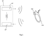
Figure 1 is a representation of the system according to the present invention; -
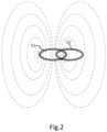
Figure 2 is a schematic representation of the transmitter inductor and the receiver inductor of the reader device of the system according to the present invention; -
Figure 3a is a side view of a second embodiment of the device of the present invention; -
Figure 3b is a top view of a second embodiment of the device of the present invention; -
Figure 3c is a bottom view of a second embodiment of the device of the present invention; -
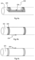
Figure 4a is a side view of a third embodiment of the device of the present invention; -
Figure 4b is a top view of a third embodiment of the device of the present invention; -
Figure 4c is a bottom view of a third t embodiment of the device of the present invention; -
Figure 5 is a side view of a fourth embodiment of the device of the present invention; -
Figure 6 is a diagram comprising a first curve representing the output signal of the reader device induced by the resonance of the tag versus the frequency (continuous line) and a second curve representing the output signal of the reader device in absence of the tag versus the frequency (dashed line); -
Figure 7a is a schematic representation of the induction balance simulation model used in the preliminary simulations of the system according to the present invention; -
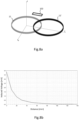
Figure 7b is curve representing the direct coupling voltage of the receiver inductor in function of the distance between the centres of the transmitter and the receiver inductors in the preliminary simulations of the system according to the present invention; -
Figure 8a is schematic representation of the induction balance simulation model used in the "small tag" simulations of the system according to the present invention; -
Figure 8b is a curve representing the voltage induction on the receiver inductor vs the tag vertical distance from the receiver inductor, in the "small tag" simulations of the system according to the present invention; -
Figure 9 is a circuit model for the tag in the "small tag" simulations of the system according to the present invention; -
Figure 10a is a curve representing the voltage induction on the receiver inductors vs the tag vertical distance from the receiver inductor, in the example wherein both the transmitter inductor and the tag inductors are resonating, in the "small tag" simulations of the system according to the present invention; -
Figure 10b shows the voltage induction on the receiver inductors vs frequency, in the example wherein both the transmitter inductor and the tag inductor are resonating, in the "small tag" simulations of the system according to the present invention. The continuous curve is referred to a vertical distance between the tag and the receiver inductor of 10 mm, the dotted curve is referred to a vertical distance between the tag and the receiver inductor of 50 mm and the dashed curve is referred to a vertical distance between the tag and the receiver inductor of 140 mm; -
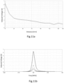
Figure 11a is a curve representing the voltage induction on the receiver inductors vs the tag vertical distance from the receiver inductor, in the example wherein the transmitter inductor, the receiver inductor and the tag inductors are resonating, in the "small tag" simulations of the system according to the present invention; -
Figure 11b shows the voltage induction on the receiver inductors vs frequency, in the example wherein the transmitter inductor, the receiver inductor and the tag inductor are resonating, in the "small tag" simulations of the system according to the present invention. The continuous curve is referred to a vertical distance between the tag and the receiver inductor of 10 mm, the dotted curve is referred to a vertical distance between the tag and the receiver inductor of 50 mm and the dashed curve is referred to a vertical distance between the tag and the receiver inductor of 140 mm; -
Figure 12a is schematic representation of the induction balance simulation model used in the "iron tag" simulations of the system according to the present invention; -
Figure 12b is a curve representing the voltage induction on the receiver inductor vs the iron sheet vertical distance from the receiver inductor, in the "iron tag" simulations of the system according to the present invention; -
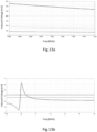
Figure 13a shows the voltage induction on the receiver inductors vs frequency, in the example wherein both transmitter inductor and the receiver inductor are resonating, in the "iron tag" simulations of the system according to the present invention. The continuous curve is referred to a vertical distance between the iron sheet and the receiver inductor of 10 mm, the dotted curve is referred to a vertical distance between the iron sheet and the receiver inductor of 50 mm and the dashed curve is referred to a vertical distance between the iron sheet and the receiver inductor of 140 mm; -
Figure 13b is a diagram relative to the "iron tag" simulations, comprising a first curve representing the output signal of the reader device induced by the resonance of the tag versus the frequency (continuous line), a second curve representing the output signal of the reader device induced by the resonance of the iron sheet versus the frequency (dashed line) and a third curve representing the output signal of the reader device in absence of the tag versus the frequency (dotted line); -
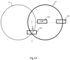
Figure 14 is schematic representation of the induction balance simulation model used in simulations for evaluating the reader device locating accuracy; -
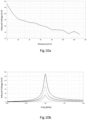
Figure 15a is a curve representing shows the voltage induction on the receiver inductors vs frequency with a tag sweep along x axis; and -
Figure 15b is a curve representing shows the voltage induction on the receiver inductors vs frequency with a tag sweep along y axis. - Referring to
Figure 1 , a first embodiment of the device of the present invention comprises: - a nasogastric tube (101); and
- a tag (102) placed on the flexible tube (101).
- The tag (102) is a passive resonant structure having a resonance frequency band, and is configured to interfere with a time varying magnetic field external to the device by changing its amplitude and/or its spatial distribution, the external magnetic field having a frequency comprised in the resonance frequency band.
- The tag (102) is placed on the distal end of the tube (101) and comprises one inductor constituted by a coil wrapped around the tube and having a resonance frequency band with a central frequency comprised between 100 kHz and 5 MHz, the central frequency being, preferably, equal to 1 MHz.
- Referring to
Figure 1 ,3a, 3b, 3c , a second embodiment of the device (100) of the present invention comprises: - a nasogastric tube (101); and
- a tag (102) placed on the flexible tube (101).
- The tag (102) is a passive resonant structure having a resonance frequency band, and is configured to interfere with a time varying magnetic field external to the device (100) by changing its amplitude and/or its spatial distribution, the external magnetic field having a frequency comprised in the resonance frequency band.
- The tag (102) is placed on the distal end of the tube (101) and comprises one capacitor (104) and one inductor (103) constituted by a coil (103), having a resonance frequency band with a central frequency comprised between 100 kHz and 5 MHz, the central frequency being, preferably, equal to 1 MHz.
- The coil (103) is wrapped around the tube (101) and, as shown in
figures 3a, 3b and 3c , comprises a first curvilinear portion of wires, a second curvilinear portion of wires and rectilinear portion of wires, that is parallel to the central axis of the tube and is comprised between the curvilinear portions. The two curvilinear portions of wires are wrapped around the tube (101) in such a way to be symmetrical with respect to central axis of the tube (101). The capacitor (104) is placed in the middle point of the rectilinear portion of wires. - Referring to
Figure 1 ,4a, 4b, 4c , a third embodiment of the device (200) of the present invention comprises: - a nasogastric tube (101); and
- a tag (102) placed on the flexible tube (101).
- The tag (102) is a passive resonant structure having a resonance frequency band and is configured to interfere with a time varying magnetic field external to the device (200) by changing its amplitude and/or the spatial distribution, the external magnetic field having a frequency comprised in the resonance frequency band.
- The tag (102) is placed on the distal end of the tube (101) and comprises one capacitor (204) and one inductor (203) constituted by a coil (203), having a resonance frequency band with a central frequency comprised between 100 kHz and 5 MHz, the central frequency being, preferably, equal to 1 MHz.
- The coil (203) is wrapped around the tube (201) and, as shown in
figures 4a, 4b and 4c , comprises a first curvilinear portion of wires, a second curvilinear portion of wires and a rectilinear portion of wires, that is parallel to the central axis of the tube and is comprised between the curvilinear portions. The two curvilinear portions of wires are wrapped around the tube (101) in such a way to be symmetrical with respect to an axis perpendicular to the central axis of the tube (101). The capacitor (204) is placed in the middle point of the rectilinear portion of wires. - Referring to
Figure 1 , and5 a fourth embodiment (300) of the device of the present invention comprises: - a nasogastric tube (101); and
- a tag (102) placed on the flexible tube (101).
- The tag (102) is a passive resonant structure having a resonance frequency band, and is configured to interfere with a time varying magnetic field external to the device (300) by changing its amplitude and/or its spatial distribution, the external magnetic field having a frequency comprised in the resonance frequency band.
- The tag (102) is placed on the distal end of the tube (101) and comprises one capacitor (304) and one inductor (303) constituted by a coil (303), having a resonance frequency band with a central frequency comprised between 100 kHz and 5 MHz, the central frequency being, preferably, equal to 1 MHz. The coil (103), as shown in
figure 5 , is wrapped around the tube (101) in a circumferential manner so to cover almost all the distal end of the tube (101). - In all the four embodiments mentioned above, the capacitor (104, 204, 304) is, preferably, a surface mount technology capacitor. In alternative the capacitor (104, 204, 304) can be also an interdigital capacitor. The preferred material used for the tag (101) is biocompatible and non-ferromagnetic material, in order to guarantee full compatibility with diagnostic systems based on Magnetic Resonance Imaging (MRI). Among different possible conductive materials with such characteristics, such as titanium-vanadium alloys, copper, low carbon stainless steel, titanium and silver paste, copper is the preferred material for the resonant tag since it shows the highest quality factor among the others, having the narrower and sharper resonance peak in the frequency response.
- Referring to
Figure 1 and2 , a first embodiment of the system of the present invention comprises: - a nasogastric tube (101):
- a tag (102) placed on the flexible tube (101); and
- a reader device (10) comprising:
- means (10') for generating a source time varying magnetic field; and
- means (10") for detecting a derived time varying magnetic field;
- The tag (102) can have the characteristics of the tag (102) already described above, relatively to the first, second, third and fourth embodiment of the device (100, 200, 300) according to the present invention.
- The means (10') for generating the source magnetic field comprise an inductor (11), or transmitter inductor (11) and the means (10") for detecting the derived magnetic field comprise another inductor (11'), or receiver inductor (11'). As shown in
Figure 2 , the transmitter inductor (11) and the receiver inductor (11') partially overlap. The transmitter inductor (11) produces a magnetic field that induces a voltage, by Faraday Law, on the receiver inductor (11'). Thanks to the fact that the first inductor (11) and the second inductor (11') overlap only partially, the induced voltage on the second inductor (11') can be canceled out. This "equilibrium" situation can be easily overturned by introducing some external object such as the tag (102). In such a case, due to the slightly modified magnetic field distribution, the receiver inductor (11') comes out of its "equilibrium" and its induced voltage is now no longer zero. - Referring to
Figure 1 , a second embodiment of the system of the present invention comprises: - a nasogastric tube (101):
- a tag (102) placed on the flexible tube (101); and
- a reader device (10) comprising:
- means (10') for generating a source time varying magnetic field; and
- means (10") for detecting a derived time varying magnetic field;
- The tag (102) can have the characteristics of the tag (102) already described above, relatively to the first, second, third and fourth embodiment of the device (100, 200, 300) according to the present invention.
- The means (10') for generating the source magnetic field comprise an inductor (11), or transmitter inductor (11) and a capacitor and the means (10") for detecting the derived magnetic field comprise another inductor (11'), or receiver inductor (11').
- Referring to
Figure 1 , a third embodiment of the system of the present invention comprises: - a nasogastric tube (101):
- a tag (102) placed on the flexible tube (101); and
- a reader device (10) comprising:
- means (10') for generating a source time varying magnetic field; and
- means (10") for detecting a derived time varying magnetic field;
- The tag (102) can have the characteristics of the tag (102) already described above, relatively to the first, second, third and fourth embodiment of the device (100, 200, 300) according to the present invention.
- The means (10') for generating the source magnetic field comprise an inductor (11), or transmitter inductor (11), while the means (10") for detecting the derived magnetic field comprise another inductor (11'), or receiver inductor (11') and a capacitor.
- Referring to
Figure 1 , a fourth embodiment of the system of the present invention comprises: - a nasogastric tube (101):
- a tag (102) placed on the flexible tube (101); and
- a reader device (10) comprising:
- means (10') for generating a source time varying magnetic field; and
- means (10") for detecting a derived time varying magnetic field;
- The tag (102) can have the characteristics of the tag (102) already described above, relatively to the first, second, third and fourth embodiment of the device (100, 200, 300) according to the present invention.
- The means (10') for generating the source magnetic field comprise an inductor (11), or transmitter inductor (11) and a first capacitor. Even the means (10") for detecting the derived magnetic field comprise another inductor (11'), or receiver inductor (11') and a second capacitor.
- In all the embodiments of the systems described above (from the first to the fourth), and as detailed in the following paragraphs relative to the methods according to the present invention, when the system is in use, the reader (10) can be moved in proximity to the chest and abdomen of the patient and, when the response of the reader is above a given threshold, the nasogastric tube (101) is considered as localized.
- Referring to
Figure 1 , a fifth embodiment of the system of the present invention comprises: - a nasogastric tube (101):
- a tag (102) placed on the flexible tube (101); and
- a reader device (10) comprising:
- means (10') for generating a source time varying magnetic field; and
- means (10") for detecting a derived time varying magnetic field;
- The tag (102) can have the characteristics of the tag (102) already described above, relatively to the first, second, third and fourth embodiment of the device (100, 200, 300) according to the present invention.
- The means (10') for generating the source magnetic field comprise an inductor (11), or transmitter inductor (11). Together to the transmitter inductor, the means (10') for generating the source magnetic field can comprise also a capacitor. The means (10") for detecting the derived magnetic field, instead, comprise:
- a bidimensional array of inductors placed at different distance from the tag (102), each of the inductor of the array being placed at its own distance from the tag (102) and producing an output signal dependent on the amplitude and on the distribution of the derived time varying magnetic field; and
- a processor configured for:
- calculating a maximum value of the output signals;
- identifying an inductor of interest as the inductor of the array producing the maximum value; and
- localizing the tag (102) based on the distance of the inductor of interest from the tag (102).
- As previously mentioned, thanks to the presence of the bidimensional array of inductors, it is possible to locate the tag without moving the reader (10).
- Referring to
Figures 1 and6 , a first embodiment of the method according to the present invention, comprises: - generating a first source time varying magnetic field external to the nasogastric tube (101), the first source magnetic field having a first frequency (13) comprised in the resonance frequency band (102);
- detecting a first derived magnetic field resulting from an interaction of the first source magnetic field with the surrounding environment, the first derived magnetic field having an amplitude;
- generating a second source time varying magnetic field external to the nasogastric tube (101), the second source magnetic field having a second frequency (13') outside from the resonance frequency band (102);
- detecting a second derived magnetic field resulting from an interaction of the first source magnetic field with the surrounding environment, the second derived magnetic field having an amplitude;
- determining, by means of a processor, the presence of the passive resonance structure (102) based on the difference between the amplitude of the first derived magnetic field and the amplitude of the second derived magnetic field, said determining comprising:
- calculating a difference between the amplitude of the first derived magnetic field and the amplitude of the second derived magnetic field;
- comparing the difference with a fixed threshold;
- identifying the passive resonance structure as present, if the difference is above the fixed threshold; and
- identifying the passive resonance structure as absent, if the difference is below the fixed threshold.
- Obviously, it can used also a number of frequencies higher than two to generate the source magnetic field and it is possible to compare a number of derived magnetic fields higher than two. For example the method of the present invention can comprise the following steps:
- generating a first source time varying magnetic field external to the nasogastric tube (101), the first source magnetic field having a first frequency (13) comprised in the resonance frequency band (102);
- detecting a first derived magnetic field resulting from an interaction of the first source magnetic field with the surrounding environment, the first derived magnetic field having an amplitude;
- generating a second source time varying magnetic field external to the nasogastric tube (101), the second source magnetic field having a second frequency (13') outside from the resonance frequency band (102);
- detecting a second derived magnetic field resulting from an interaction of the first source magnetic field with the surrounding environment, the second derived magnetic field having an amplitude;
- generating a third source time varying magnetic field external to the nasogastric tube (101), the third source magnetic field having a third frequency outside from the resonance frequency band (102);
- detecting a third derived magnetic field resulting from an interaction of the first source magnetic field with the surrounding environment, the second derived magnetic field having an amplitude; and
- determining, by means of a processor, the presence of the passive resonance structure (102) based on the difference between the amplitude of the first derived magnetic field and the amplitude of the second derived magnetic field and the difference between the amplitude of the first derived magnetic field and the amplitude of the third derived magnetic field, said determining comprising:
- calculating a first difference between the amplitude of the first derived magnetic field and the amplitude of the second derived magnetic field;
- calculating a second difference between the amplitude of the first derived magnetic field and the amplitude of the third derived magnetic field;
- comparing the first and the second difference with a fixed threshold; and
- identifying the passive resonance structure as present, if both the first and the second difference is above the fixed threshold; or if at least one among the first and the second difference is above the threshold.
- Referring to
Figure 1 , a second embodiment of the method according to the present invention, comprises: - generating a first source time varying magnetic field external to the nasogastric tube (101), the first source magnetic field having a frequency comprised in the resonance frequency band;
- detecting, by using means (10") for detecting a derived time varying magnetic field, a first derived magnetic field resulting from an interaction of the first source magnetic field with the surrounding environment, the means (10") for detecting a derived time varying magnetic field being in a first position and the first derived magnetic field having an amplitude;
- moving the means (10") for detecting a derived time varying magnetic field, from a first position to a second position;
- generating a second source time varying magnetic field external to the nasogastric tube (101), the second source magnetic field having a frequency comprised in the resonance frequency band;
- detecting, by using the means (10") for detecting a derived time varying magnetic field, a second derived magnetic field resulting from an interaction of the second source magnetic field with the surrounding environment, the means (10") for detecting a derived time varying magnetic field being in a second position and the second derived magnetic field having an amplitude;
- determining, by means of a processor, the position of the passive resonance structure (102) with respect to the means (10") for detecting a derived time varying magnetic field based on the comparison between the amplitude of the first derived magnetic field and the amplitude of the second derived magnetic field, said determining comprising:
- finding a maximum value between the amplitude of the first derived magnetic field and the amplitude of the second derived magnetic field;
- identifying a position of interest as the position of the means (10") for detecting a derived magnetic field when detecting an amplitude of the derived magnetic field equal to the maximum value;
- localizing the nasogastric tube (101) based on the position of interest.
- Two types of simulation have been carried out in order to provide a reliable model. Finite element method (FEM) simulation using Ansys Maxwell3D and circuital simulation using Ansys Simplorer. Once the 3D model is simulated with Ansys Maxwell3D, its solution is linked into a circuital model where external conditioning components are added to the model and simulated with Ansys Simplorer.
- Ansys Maxwell3D allows to simulate the behavior of the coils' electromagnetic fields. In
Figure 7a the 3D model is shown which has some intrinsic proprieties like the number of turns that are directly set in the simulation setup.Table 1 - Value of the transmitter and Receiver inductors model Inductor (Coil) Transmitter Receiver Number of turns 4 4 Diameter [mm] 60 60 Material Coil Copper Copper Applied Voltage 10V 0V - The model is composed of two coils, as shown in
Figure 7a . The gray one is the transmitting coil so an excitation port (14) is applied to it and the black one is the receiving coil and a reading port (14') is applied. - The goal of this simulation is to find the best position for the receiver coil (11') in such a way to obtain a minimum direct coupling between them.
- A single point frequency analysis was performed by varying the horizontal position of the receiver coil (11') with respect to the transmitter coil (11).
Figure 7b shows the voltage induction vs the position of the receiver coil (11'). In position 0 (shift = 0.00mm, the two coils are completely overlapping) the voltage induction is the maximum since the coils are perfectly coupled. By shifting the receiver coil (11') away, its voltage induction decreases and reaches a minimum in the position of 45.38mm and then increases again until the two coil are completely detached. Our application's goal is to obtain minimum direct coupling between receiver (11') and transmitter (11) coils in absence of any external object (nasogastric tube's resonator) and this happens at an interaxle spacing of 45.38 mm between the two coils. - For the purpose of the present description with the expression "small tag" we intend the tag that has a dimension which is suitable for the nasogastric tube. The "small tag" simulation gives us an understanding of the influence of a real sized sensor on the whole system performance.
- The "small tag" simulations are based on the setup of the "preliminary simulations" and the transmitter and receiver coil positions have been kept fixed at the reciprocal distance of 45.38 mm.
-
Figure 8a shows the design explained in the "preliminary simulations" paragraph, with the addition of the tag (102). - Parametric simulations are carried out by varying the vertical distance between tag and reading configuration. Without any circuital conditioning (none of the coils is resonating) the voltage inducted is displayed in
Figure 8b . As shown inFigure 8b the inducted voltage exponentially decays with the distance from the reader. - Capacitors are added also here to each coil (see
Figure 9 ), in order make them resonant at 1 MHz. - Two simulations with different configurations are carried out:
- 1. transmitter coil resonating
- 2. both transmitter and receiving coils resonating
-
Figure 10a and Figure 10b show the result obtained with the simulation with transmitter coil resonating. - In order to enhance the induced voltage, also the receiving coil is made resonant in the in the
Figures 11a and 11b . It is possible to observe that with both transmitter and receiver coils resonating, the signal strength becomes much better (it can be noted that the induced voltage inFigure 10a and 10b is given in milli-volts, whereas that ofFigure 11a and Figure 11b is given in volts, i.e. a 1000x factor large). - Referring to
Figure 12a , the magnetic field produced by the transmitter coil (11) is obviously affected by any nearby conductive object. In order to verify the possibility to distinguish the nasogastric tube from any other metallic object, simulations are carried by considering an iron sheet (15). In this wat, it is possible to comprehend how the receiver coil (11') induced voltage is affected by the iron sheet (15). The iron sheet (15) dimensions are 20x7xlmm. - At a single frequency the behavior of the voltage induction is pretty the same as in the case of the small tag. Behavior over various frequencies is however different. The small tag exhibits a marked response at its resonant frequency. Non-resonant objects, on the other hand, have a rather flat response over a wide spectrum of frequencies, as clearly visible in the
Figure 13a . - The frequency response in
Figure 13a shows that the curves are flat and this means that the iron sheet, and conductive non resonant objects in general, produce a flat frequency response over the investigated frequency band. - In order to distinguish between "iron sheet", "resonant tags" and "no objects at all", at least two frequency points need to be measured.
- A comparative simulation is performed to better understand the different frequency responses of a resonant tag, an iron sheet and no object.
-
Figure 13b displays the frequency response of three real cases. As we can see the frequency response of the iron sheet (dotted line) is flat: this means that it is easy to distinguish. The resonant tag is detectable by its frequency of resonance. Absence of any object is detectable by the very low signal level. Therefore, conducting a two-frequency point analysis will allow to distinguish the resonant tags from any other conductive objects. - Referring to the
Figure 14 , to evaluate how well the reader can identify the tag's position, a simulation has been performed where the tag (102) is moved in x and y directions with respect to the reader coils (11, 11'). - The simulation shows that a change of the tag's position results in a change of the voltage induced in the receiving coil (11'). Adequately processing this information yields an estimated locating accuracy of about ±1cm. As showed in
Figure 15a and 15b , showing the effect of the tag sweep on the receiver coil induced voltage, a maximum voltage induction on receiver is obtained when the tag is exactly in the origin position (i.e. right above the reader transmitter and receiver coils).
| Parameters | Values |
| Amplitude, frequency | 10V, 1MHz |
| Cris_prim | 11.8nF |
| Cpp | 3.6pF |
| Rprim | 0.4Ω |
| Rsec | 0.4Ω |
| Cps | 3.6pF |
| Cris_sec | 11nF |
| Rtag | 0.3Ω |
| Cris_tag | 32.5nF |
Claims (15)
- A nasogastric device for enteral feeding (100, 200, 300) comprising:- a nasogastric tube (101); and- a tag (102) placed on the flexible tube (101);characterized in that the tag (102) is a passive resonant structure having a resonance frequency band, the tag (102) being configured to interfere with a time varying magnetic field external to the device (100, 200, 300) by changing its amplitude and/or the spatial distribution, the external magnetic field having a frequency comprised in the resonance frequency band.
- The device according to claim 1 wherein the tag (102) comprises at least one inductor (103, 203, 303) and at least one capacitor (104, 204, 304).
- The device according to any of the preceding claims wherein the flexible tube (101) has a distal end and proximal end, the tag (102) being placed on the distal end.
- The device (100, 200, 300) according to the preceding claim wherein the resonance frequency band has a central frequency comprised between 100 kHz and 5 MHz.
- The device (100, 200, 300) according to the preceding claim wherein the central frequency is equal to 1 MHz.
- The device (100, 200, 300) according to any of the claims from 2 to 4 wherein the at least one capacitor (104, 204, 304) is a surface mount technology capacitor.
- The device (100, 200, 300) according to any of the claims from 2 to 4 wherein the inductor (103, 203, 303) is a coil (103, 203, 303) wrapped at least partially around the tube (101).
- A system (10, 100, 200, 300) for enteral feeding (100, 200, 300) comprising:- a nasogastric tube (101);- a tag (102) placed on the flexible tube (101); and- a reader device (10) comprising:characterized in that the tag (102) is a passive resonant structure having a resonance frequency band, and is configured to interfere with the source magnetic field, by changing its amplitude and/or spatial distribution in such a way to originate the derived magnetic field having its own amplitude and distribution, the source magnetic field having a frequency comprised in the resonance frequency band.• means (10') for generating a source time varying magnetic field; and• means (10") for detecting a derived time varying magnetic field;
- The system according to claim 8 wherein the tag (102) comprises at least one inductor (103, 203, 303) and at least one capacitor (104, 204, 304).
- The system according to claim 8 wherein the means (10') for generating the source magnetic field comprise at least an inductor (11) and a capacitor (12)
- The system according to any of the claims from 8 to 10 wherein the means (10") for detecting the derived magnetic field comprise at least an inductor (11') and a capacitor (12').
- The system according to any of the claim from 8 to 11, wherein the means (10") for detecting a derived time varying magnetic field comprise:- a bidimensional array of inductors placed at different distance from the tag (102), each of the inductor of the array being placed at its own distance from the tag (102) and producing an output signal dependent on the amplitude and on the distribution of the derived time varying magnetic field; and- a processor configured for:• calculating a maximum value of the output signals;• identifying an inductor of interest as the inductor of the array producing the maximum value; and• localizing the tag (102) based on the distance of the inductor of interest from the tag (102).
- A method for localizing a nasogastric tube comprising:- generating a source time varying magnetic field external to the nasogastric tube (101) having its own amplitude and spatial distribution; and- detecting a derived magnetic field resulting from an interaction of the first source magnetic field with a surrounding environment;characterized in that the interaction of the source magnetic field with the surrounding environment comprises:- inducing the resonance of a passive resonance structure (102) placed on the tube (101) and having a resonance frequency band, by means of the source magnetic field, said source magnetic field having a frequency comprised in the resonance frequency band; and- changing, the amplitude and/or the distribution of the source magnetic field, by means of the passive resonance structure (102), originating the derived magnetic field.
- The method according to claim 13 comprising:- generating a first source time varying magnetic field external to the nasogastric tube (101), the first source magnetic field having a first frequency (13) comprised in the resonance frequency band (102);- detecting a first derived magnetic field resulting from an interaction of the first source magnetic field with the surrounding environment, the first derived magnetic field having an amplitude;- generating a second source time varying magnetic field external to the nasogastric tube (101), the second source magnetic field having a second frequency (13') outside from the resonance frequency band (102);- detecting a second derived magnetic field resulting from an interaction of the first source magnetic field with the surrounding environment, the second derived magnetic field having an amplitude;- determining, by means of a processor, the presence of the passive resonance structure (102), and, thus, of the nasogastric tube (101),based on the difference between the amplitude of the first derived magnetic field and the amplitude of the second derived magnetic field, said determining comprising:• calculating a difference between the amplitude of the first derived magnetic field and the amplitude of the second derived magnetic field;• comparing the difference with a fixed threshold;• identifying the passive resonance structure as present, if the difference is above the fixed threshold; and• identifying the passive resonance structure as absent, if the difference is below the fixed threshold.
- The method according to claim 13 comprising:- generating a first source time varying magnetic field external to the nasogastric tube (101), the first source magnetic field having a frequency comprised in the resonance frequency band;- detecting, by using means (10") for detecting a derived time varying magnetic field, a first derived magnetic field resulting from an interaction of the first source magnetic field with the surrounding environment, the means (10") for detecting a derived time varying magnetic field being in a first position and the first derived magnetic field having an amplitude;- moving the means (10") for detecting a derived time varying magnetic field, from a first position to a second position;- generating a second source time varying magnetic field external to the nasogastric tube (101), the second source magnetic field having a frequency comprised in the resonance frequency band;- detecting, by using the means (10") for detecting a derived time varying magnetic field, a second derived magnetic field resulting from an interaction of the second source magnetic field with the surrounding environment, the means (10") for detecting a derived time varying magnetic field being in a second position and the second derived magnetic field having an amplitude;- determining, by means of a processor, the position of the passive resonance structure (102) with respect to the means (10") for detecting a derived time varying magnetic field based on the comparison between the amplitude of the first derived magnetic field and the amplitude of the second derived magnetic field, said determining comprising:• finding a maximum value between the amplitude of the first derived magnetic field and the amplitude of the second derived magnetic field;• identifying a position of interest as the position of the means (10") for detecting a derived magnetic field when detecting an amplitude of the derived magnetic field equal to the maximum value;• localizing the nasogastric tube (101) based on the position of interest.
Priority Applications (1)
| Application Number | Priority Date | Filing Date | Title |
|---|---|---|---|
| EP23201865.5A EP4534066B1 (en) | 2023-10-05 | 2023-10-05 | Nasogastric device and system thereof |
Applications Claiming Priority (1)
| Application Number | Priority Date | Filing Date | Title |
|---|---|---|---|
| EP23201865.5A EP4534066B1 (en) | 2023-10-05 | 2023-10-05 | Nasogastric device and system thereof |
Publications (3)
| Publication Number | Publication Date |
|---|---|
| EP4534066A1 true EP4534066A1 (en) | 2025-04-09 |
| EP4534066B1 EP4534066B1 (en) | 2026-02-04 |
| EP4534066C0 EP4534066C0 (en) | 2026-02-04 |
Family
ID=88315898
Family Applications (1)
| Application Number | Title | Priority Date | Filing Date |
|---|---|---|---|
| EP23201865.5A Active EP4534066B1 (en) | 2023-10-05 | 2023-10-05 | Nasogastric device and system thereof |
Country Status (1)
| Country | Link |
|---|---|
| EP (1) | EP4534066B1 (en) |
Citations (8)
| Publication number | Priority date | Publication date | Assignee | Title |
|---|---|---|---|---|
| US6072383A (en) * | 1998-11-04 | 2000-06-06 | Checkpoint Systems, Inc. | RFID tag having parallel resonant circuit for magnetically decoupling tag from its environment |
| US20030004411A1 (en) * | 1999-03-11 | 2003-01-02 | Assaf Govari | Invasive medical device with position sensing and display |
| US20070265690A1 (en) * | 2006-05-12 | 2007-11-15 | Yoav Lichtenstein | Position tracking of passive resonance-based transponders |
| CN109864892A (en) | 2017-12-03 | 2019-06-11 | 恩维森医疗有限公司 | Feeding tube with electromagnetic sensor |
| US20220117676A1 (en) | 2018-10-17 | 2022-04-21 | Envizion Medical Ltd. | Insertion device positioning guidance system and method |
| WO2023119296A1 (en) * | 2021-12-23 | 2023-06-29 | Envizion Medical Ltd. | Insertion device positioning guidance system and method |
| US20230285249A1 (en) * | 2017-12-03 | 2023-09-14 | Envizion Medical Ltd. | Feeding tube with electromagnetic sensor and camera |
| US20230297802A1 (en) * | 2020-09-16 | 2023-09-21 | Elucent Medical, Inc. | Systems and methods comprising linked localization agents |
-
2023
- 2023-10-05 EP EP23201865.5A patent/EP4534066B1/en active Active
Patent Citations (8)
| Publication number | Priority date | Publication date | Assignee | Title |
|---|---|---|---|---|
| US6072383A (en) * | 1998-11-04 | 2000-06-06 | Checkpoint Systems, Inc. | RFID tag having parallel resonant circuit for magnetically decoupling tag from its environment |
| US20030004411A1 (en) * | 1999-03-11 | 2003-01-02 | Assaf Govari | Invasive medical device with position sensing and display |
| US20070265690A1 (en) * | 2006-05-12 | 2007-11-15 | Yoav Lichtenstein | Position tracking of passive resonance-based transponders |
| CN109864892A (en) | 2017-12-03 | 2019-06-11 | 恩维森医疗有限公司 | Feeding tube with electromagnetic sensor |
| US20230285249A1 (en) * | 2017-12-03 | 2023-09-14 | Envizion Medical Ltd. | Feeding tube with electromagnetic sensor and camera |
| US20220117676A1 (en) | 2018-10-17 | 2022-04-21 | Envizion Medical Ltd. | Insertion device positioning guidance system and method |
| US20230297802A1 (en) * | 2020-09-16 | 2023-09-21 | Elucent Medical, Inc. | Systems and methods comprising linked localization agents |
| WO2023119296A1 (en) * | 2021-12-23 | 2023-06-29 | Envizion Medical Ltd. | Insertion device positioning guidance system and method |
Also Published As
| Publication number | Publication date |
|---|---|
| EP4534066B1 (en) | 2026-02-04 |
| EP4534066C0 (en) | 2026-02-04 |
Similar Documents
| Publication | Publication Date | Title |
|---|---|---|
| US12226266B2 (en) | Systems and methods for detecting magnetic markers for surgical guidance | |
| JP5755393B2 (en) | Reduced magnetic field distortion in medical devices | |
| US20140276010A1 (en) | Systems and Methods for Tracking Objects Using Magnetoresistance | |
| EP1181891B1 (en) | A system for detecting a position of a magnet associated with an indwelling medical device | |
| US5944023A (en) | Systems and methods for determining the location of an implanted device including a magnet | |
| EP1891895B1 (en) | Distortion-immune position tracking using frequency extrapolation | |
| US20100113917A1 (en) | System and method for tracking object | |
| US7658541B2 (en) | Apparatus for universal electromagnetic navigation target for fluoroscopic systems | |
| CN102427762A (en) | Arrangement and method for influencing and/or detecting magnetic particles | |
| AU2008304622B2 (en) | MRI phase visualization of interventional devices | |
| US20070106148A1 (en) | Electronic circuits to improve the sensitivity of magnetic resonance tracking catheters and intraluminal RF coils | |
| EP4534066A1 (en) | Nasogastric device and system thereof | |
| AU2026201049A1 (en) | System and method for detecting medical device location and orientation in relation to patient anatomy | |
| US20100113918A1 (en) | System and method for tracking object | |
| AU2013204411B2 (en) | Reduced field distortion in medical tools | |
| Dekdouk et al. | Assessing the feasibility of detecting a hemorrhagic type stroke using a 16 channel magnetic induction system | |
| HK1107662A (en) | Reduced field distortion in medical tools |
Legal Events
| Date | Code | Title | Description |
|---|---|---|---|
| PUAI | Public reference made under article 153(3) epc to a published international application that has entered the european phase |
Free format text: ORIGINAL CODE: 0009012 |
|
| STAA | Information on the status of an ep patent application or granted ep patent |
Free format text: STATUS: THE APPLICATION HAS BEEN PUBLISHED |
|
| AK | Designated contracting states |
Kind code of ref document: A1 Designated state(s): AL AT BE BG CH CY CZ DE DK EE ES FI FR GB GR HR HU IE IS IT LI LT LU LV MC ME MK MT NL NO PL PT RO RS SE SI SK SM TR |
|
| STAA | Information on the status of an ep patent application or granted ep patent |
Free format text: STATUS: REQUEST FOR EXAMINATION WAS MADE |
|
| GRAP | Despatch of communication of intention to grant a patent |
Free format text: ORIGINAL CODE: EPIDOSNIGR1 |
|
| STAA | Information on the status of an ep patent application or granted ep patent |
Free format text: STATUS: GRANT OF PATENT IS INTENDED |
|
| 17P | Request for examination filed |
Effective date: 20251006 |
|
| RIC1 | Information provided on ipc code assigned before grant |
Ipc: A61J 15/00 20060101AFI20251009BHEP Ipc: A61B 34/20 20160101ALI20251009BHEP |
|
| GRAJ | Information related to disapproval of communication of intention to grant by the applicant or resumption of examination proceedings by the epo deleted |
Free format text: ORIGINAL CODE: EPIDOSDIGR1 |
|
| STAA | Information on the status of an ep patent application or granted ep patent |
Free format text: STATUS: REQUEST FOR EXAMINATION WAS MADE |
|
| INTG | Intention to grant announced |
Effective date: 20251029 |
|
| RIN1 | Information on inventor provided before grant (corrected) |
Inventor name: PERREN, ANDREAS Inventor name: PORETTI, SAMUEL Inventor name: HAJDAJ, FATLIND |
|
| GRAP | Despatch of communication of intention to grant a patent |
Free format text: ORIGINAL CODE: EPIDOSNIGR1 |
|
| STAA | Information on the status of an ep patent application or granted ep patent |
Free format text: STATUS: GRANT OF PATENT IS INTENDED |
|
| GRAS | Grant fee paid |
Free format text: ORIGINAL CODE: EPIDOSNIGR3 |
|
| GRAA | (expected) grant |
Free format text: ORIGINAL CODE: 0009210 |
|
| STAA | Information on the status of an ep patent application or granted ep patent |
Free format text: STATUS: THE PATENT HAS BEEN GRANTED |
|
| INTC | Intention to grant announced (deleted) | ||
| INTG | Intention to grant announced |
Effective date: 20251219 |
|
| AK | Designated contracting states |
Kind code of ref document: B1 Designated state(s): AL AT BE BG CH CY CZ DE DK EE ES FI FR GB GR HR HU IE IS IT LI LT LU LV MC ME MK MT NL NO PL PT RO RS SE SI SK SM TR |
|
| REG | Reference to a national code |
Ref country code: CH Ref legal event code: F10 Free format text: ST27 STATUS EVENT CODE: U-0-0-F10-F00 (AS PROVIDED BY THE NATIONAL OFFICE) Effective date: 20260204 Ref country code: GB Ref legal event code: FG4D |
|
| REG | Reference to a national code |
Ref country code: CH Ref legal event code: R17 Free format text: ST27 STATUS EVENT CODE: U-0-0-R10-R17 (AS PROVIDED BY THE NATIONAL OFFICE) Effective date: 20260209 |
|
| REG | Reference to a national code |
Ref country code: IE Ref legal event code: FG4D |
|
| U01 | Request for unitary effect filed |
Effective date: 20260209 |
|
| U07 | Unitary effect registered |
Designated state(s): AT BE BG DE DK EE FI FR IT LT LU LV MT NL PT RO SE SI Effective date: 20260216 |