EP4533968A1 - Composite induction heating susceptor, preparation method therefor and use thereof - Google Patents
Composite induction heating susceptor, preparation method therefor and use thereof Download PDFInfo
- Publication number
- EP4533968A1 EP4533968A1 EP23853972.0A EP23853972A EP4533968A1 EP 4533968 A1 EP4533968 A1 EP 4533968A1 EP 23853972 A EP23853972 A EP 23853972A EP 4533968 A1 EP4533968 A1 EP 4533968A1
- Authority
- EP
- European Patent Office
- Prior art keywords
- susceptor
- induction heating
- temperature
- range
- composite
- Prior art date
- Legal status (The legal status is an assumption and is not a legal conclusion. Google has not performed a legal analysis and makes no representation as to the accuracy of the status listed.)
- Pending
Links
Images


Classifications
-
- H—ELECTRICITY
- H05—ELECTRIC TECHNIQUES NOT OTHERWISE PROVIDED FOR
- H05B—ELECTRIC HEATING; ELECTRIC LIGHT SOURCES NOT OTHERWISE PROVIDED FOR; CIRCUIT ARRANGEMENTS FOR ELECTRIC LIGHT SOURCES, IN GENERAL
- H05B6/00—Heating by electric, magnetic or electromagnetic fields
- H05B6/02—Induction heating
- H05B6/10—Induction heating apparatus, other than furnaces, for specific applications
- H05B6/105—Induction heating apparatus, other than furnaces, for specific applications using a susceptor
-
- A—HUMAN NECESSITIES
- A24—TOBACCO; CIGARS; CIGARETTES; SIMULATED SMOKING DEVICES; SMOKERS' REQUISITES
- A24F—SMOKERS' REQUISITES; MATCH BOXES; SIMULATED SMOKING DEVICES
- A24F40/00—Electrically operated smoking devices; Component parts thereof; Manufacture thereof; Maintenance or testing thereof; Charging means specially adapted therefor
- A24F40/50—Control or monitoring
- A24F40/57—Temperature control
-
- A—HUMAN NECESSITIES
- A24—TOBACCO; CIGARS; CIGARETTES; SIMULATED SMOKING DEVICES; SMOKERS' REQUISITES
- A24F—SMOKERS' REQUISITES; MATCH BOXES; SIMULATED SMOKING DEVICES
- A24F40/00—Electrically operated smoking devices; Component parts thereof; Manufacture thereof; Maintenance or testing thereof; Charging means specially adapted therefor
- A24F40/70—Manufacture
-
- B—PERFORMING OPERATIONS; TRANSPORTING
- B22—CASTING; POWDER METALLURGY
- B22F—WORKING METALLIC POWDER; MANUFACTURE OF ARTICLES FROM METALLIC POWDER; MAKING METALLIC POWDER; APPARATUS OR DEVICES SPECIALLY ADAPTED FOR METALLIC POWDER
- B22F3/00—Manufacture of workpieces or articles from metallic powder characterised by the manner of compacting or sintering; Apparatus specially adapted therefor ; Presses and furnaces
- B22F3/02—Compacting only
- B22F3/04—Compacting only by applying fluid pressure, e.g. by cold isostatic pressing [CIP]
-
- B—PERFORMING OPERATIONS; TRANSPORTING
- B22—CASTING; POWDER METALLURGY
- B22F—WORKING METALLIC POWDER; MANUFACTURE OF ARTICLES FROM METALLIC POWDER; MAKING METALLIC POWDER; APPARATUS OR DEVICES SPECIALLY ADAPTED FOR METALLIC POWDER
- B22F3/00—Manufacture of workpieces or articles from metallic powder characterised by the manner of compacting or sintering; Apparatus specially adapted therefor ; Presses and furnaces
- B22F3/10—Sintering only
-
- B—PERFORMING OPERATIONS; TRANSPORTING
- B22—CASTING; POWDER METALLURGY
- B22F—WORKING METALLIC POWDER; MANUFACTURE OF ARTICLES FROM METALLIC POWDER; MAKING METALLIC POWDER; APPARATUS OR DEVICES SPECIALLY ADAPTED FOR METALLIC POWDER
- B22F3/00—Manufacture of workpieces or articles from metallic powder characterised by the manner of compacting or sintering; Apparatus specially adapted therefor ; Presses and furnaces
- B22F3/12—Both compacting and sintering
- B22F3/14—Both compacting and sintering simultaneously
-
- B—PERFORMING OPERATIONS; TRANSPORTING
- B22—CASTING; POWDER METALLURGY
- B22F—WORKING METALLIC POWDER; MANUFACTURE OF ARTICLES FROM METALLIC POWDER; MAKING METALLIC POWDER; APPARATUS OR DEVICES SPECIALLY ADAPTED FOR METALLIC POWDER
- B22F3/00—Manufacture of workpieces or articles from metallic powder characterised by the manner of compacting or sintering; Apparatus specially adapted therefor ; Presses and furnaces
- B22F3/22—Manufacture of workpieces or articles from metallic powder characterised by the manner of compacting or sintering; Apparatus specially adapted therefor ; Presses and furnaces for producing castings from a slip
-
- B—PERFORMING OPERATIONS; TRANSPORTING
- B22—CASTING; POWDER METALLURGY
- B22F—WORKING METALLIC POWDER; MANUFACTURE OF ARTICLES FROM METALLIC POWDER; MAKING METALLIC POWDER; APPARATUS OR DEVICES SPECIALLY ADAPTED FOR METALLIC POWDER
- B22F5/00—Manufacture of workpieces or articles from metallic powder characterised by the special shape of the product
-
- B—PERFORMING OPERATIONS; TRANSPORTING
- B22—CASTING; POWDER METALLURGY
- B22F—WORKING METALLIC POWDER; MANUFACTURE OF ARTICLES FROM METALLIC POWDER; MAKING METALLIC POWDER; APPARATUS OR DEVICES SPECIALLY ADAPTED FOR METALLIC POWDER
- B22F7/00—Manufacture of composite layers, workpieces, or articles, comprising metallic powder, by sintering the powder, with or without compacting wherein at least one part is obtained by sintering or compression
- B22F7/02—Manufacture of composite layers, workpieces, or articles, comprising metallic powder, by sintering the powder, with or without compacting wherein at least one part is obtained by sintering or compression of composite layers
-
- A—HUMAN NECESSITIES
- A24—TOBACCO; CIGARS; CIGARETTES; SIMULATED SMOKING DEVICES; SMOKERS' REQUISITES
- A24F—SMOKERS' REQUISITES; MATCH BOXES; SIMULATED SMOKING DEVICES
- A24F40/00—Electrically operated smoking devices; Component parts thereof; Manufacture thereof; Maintenance or testing thereof; Charging means specially adapted therefor
- A24F40/40—Constructional details, e.g. connection of cartridges and battery parts
- A24F40/46—Shape or structure of electric heating means
- A24F40/465—Shape or structure of electric heating means specially adapted for induction heating
-
- H—ELECTRICITY
- H05—ELECTRIC TECHNIQUES NOT OTHERWISE PROVIDED FOR
- H05B—ELECTRIC HEATING; ELECTRIC LIGHT SOURCES NOT OTHERWISE PROVIDED FOR; CIRCUIT ARRANGEMENTS FOR ELECTRIC LIGHT SOURCES, IN GENERAL
- H05B2206/00—Aspects relating to heating by electric, magnetic, or electromagnetic fields covered by group H05B6/00
- H05B2206/02—Induction heating
- H05B2206/023—Induction heating using the curie point of the material in which heating current is being generated to control the heating temperature
Definitions
- the present application relates to the technical field of induction heating materials, in particular to a composite induction heating susceptor, preparation method thereof, and use thereof.
- a wireless temperature-controlled susceptor for induction heating an aerosol-generating substrate typically adopts a single-material stainless-steel strip or a double-layer metal foil susceptor.
- the double-layer metal foil susceptor is fabricated by combining a first susceptor material and a second susceptor material with different Curie temperatures, using discrete patching or multilayer bonding.
- the first susceptor material is often aluminum, iron, stainless-steel, or the like, while the second susceptor material is typically nickel, a nickel alloy, etc.
- the temperature control logic of such a two-layer or three-layer bonded susceptor relies on the resistance-temperature curve of the susceptor, which has a minimum resistance value near the Curie temperature of the second susceptor material. By monitoring changes in this apparent resistance, the susceptor temperature can be determined, so as to achieve temperature regulation. The temperature point for the temperature control of the susceptor is determined by the Curie temperature of the second susceptor material.
- the variety of materials that can be used as the second susceptor material is limited, in which the materials whose Curie temperatures exactly meet the required temperature threshold for aerosol formation are even fewer. Therefore, this temperature control method is limited in selection of the second susceptor material. Furthermore, susceptors fabricated using physical bonding methods may suffer from issues such as uneven temperature fields, susceptor deformation, or even cracking, which can reduce the service life of the susceptor, due to differences in the physical properties of the two susceptor materials.
- the technical problem to be solved by the present application is to overcome the limitation in selection of the second susceptor material determining the temperature point for the temperature control of the susceptor, in the double-layer or multi-layer metal foil susceptor in the prior art, and to address the issues such as uneven temperature fields, susceptor deformation, or even cracking arising from the physical bonding preparation method.
- a composite induction heating susceptor, preparation method thereof, and use thereof are provided.
- the present application provides a composite induction heating susceptor, whose raw materials include a first susceptor material and a second susceptor material, which are mixed and sintered to obtain the composite induction heating susceptor.
- the Curie temperature of the first susceptor material is in a range from 400 °C to 1000 °C.
- the present application further provides a method for preparing the composite induction heating susceptor as described above, including the following steps:
- the warm isostatic pressing is performed at a temperature in a range from 65 °C to 85 °C for a period of time in a range from 0.1 hours (h) to 1 h at a pressure in a range from 5 MPa to 45 MPa.
- the de-binding is performed at a temperature in a range from 250 °C to 550 °C for a period of time in a range from 1 h to 10 h; and/or the sintering is performed at a temperature in a range from 1100 °C to 1400 °C for a period of time in a range from 0.5 h to 15 h.
- the present application further provides use of the above-described composite induction heating susceptor, or the composite induction heating susceptor obtained through the above-described preparation method, in the field of electromagnetic induction heating.
- the slurrying step in step S1 follows conventional slurry preparation processes in the field, typically by mixing metal powders with an organic solvent and a dispersant, and then ball milling the mixture.
- a typical, non-limiting example of the slurrying step involves uniformly mixing the first susceptor material and the second susceptor material, adding ethyl acetate, n-butanol, a 5% PVB solution, and an OP dispersant, and then ball milling the mixture in a ball mill to obtain the slurry.
- the composite induction heating susceptor provided by the present application can be in the form of sheet, tube, needle, pin, mesh, filament, granule, cup form, etc.
- the temperature control logic of the composite induction heating susceptor provided by the present application is as follows: In the initial heating stage, the susceptor is heated, and the electronic controller detects an initial apparent current. As the temperature of the susceptor increases, the magnetic reluctance of the induction metal sheet increases, and correspondingly the electronic controller detects a decrease in apparent current. When the temperature of the susceptor continues to rise and approaches the Curie temperature of the low Curie temperature material in the composite induction heating susceptor, the low Curie temperature material starts to lose magnetism, resulting in a decrease in overall magnetic reluctance of the susceptor, and correspondingly the electronic controller detects a gradual increase of the apparent current. At this time, a minimum current turning point (I 1 ) appears.
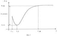
- the temperature control logics in the prior art include two types: One type involves the conventional double-layer physical bonded susceptor, which includes a first susceptor material and a second susceptor material. During the preheating period of the susceptor assembly starting from room temperature, the resistance-temperature curve (as shown in FIG. 5 , with reference to Chinese patent document CN112739229A ) of the susceptor assembly has a minimum resistance value within a ⁇ 5 °C temperature range around the Curie temperature of the second susceptor material. This minimum resistance value is used to identify a specific temperature for temperature control. In this type of susceptor, the first susceptor material is primarily responsible for heating, while the second susceptor material acts as a temperature marker.
- the magnetic properties of the second susceptor material change from ferromagnetic or ferrimagnetic to paramagnetic, accompanied by a temporary change in resistance of the material.
- the temperature control logic can only identify the temperature point by the Curie temperature of the second susceptor material, which is limited by the material, and as there is only one temperature point, it cannot achieve temperature control over a temperature range.
- the other type involves the single stainless-steel sheet susceptor.
- the temperature of the susceptor During the heating process in an induction heating device, there is a strict monotonic relationship between the temperature of the susceptor and the apparent ohmic resistance determined by the DC voltage supplied by the DC power and the DC current from the DC power. Since each single value of the apparent ohmic resistance corresponds to a unique temperature, this strict monotonic relationship allows the temperature of the susceptor to be determined based on the apparent ohmic resistance without direct contact with the induction heating device.
- This temperature control logic needs an obvious change in the apparent ohmic resistance of the stainless-steel sheet corresponding to temperature. In the correspondence relationship of common stainless-steel sheets, the change in apparent ohmic resistance within a given temperature range is usually too small, making the temperature control difficult to be precise.
- the technical solutions provided in the present application have the following advantages:
- the composite induction heating susceptor provided by the present application is obtained by mixing the first susceptor material and the second susceptor material and then sintering the mixture.
- susceptors with different temperature control ranges and Curie temperatures can be achieved, greatly enhancing the applicability of the susceptor and breaking the limitation in selection of the second susceptor material, which determines the temperature point for the susceptor temperature control.
- the obtained susceptor has a stable current-temperature linear relationship, and this new control logic can realize temperature control of the susceptor in electromagnetic induction heating.
- the sintering process forms a single-layer composite material, achieving a susceptor with homogeneous material properties of the overall structure, ensuring that the susceptor does not deform, bend, or crack during use.
- the susceptor has a uniform heat distribution, and the aerosol formed is stable and consistent.
- the composite induction heating susceptor provided in the present application, through further limitation of the first and second susceptor materials, physical properties of the susceptor, such as thermal expansion coefficient, strength, toughness, magnetic properties, and electrical performance, can be uniformly controlled and adjusted according to application requirements, thereby broadening the application range.
- the method for preparing the composite induction heating susceptor involves evenly mixing the metallic powders of the first and second susceptor materials, slurrying the mixture, and then shaping, de-binding, and sintering the slurry according to a needed shape, thereby finally obtaining the composite induction heating susceptor.
- This method is simple and mature, and in post-processing (such as rolling treatment), the process is simple and easy to implement, significantly reducing manufacturing costs.
- the composite induction heating susceptor In use of the composite induction heating susceptor provided by the present application, the composite induction heating susceptor has a monotonic and stable current-temperature curve within a specific temperature range during electromagnetic induction heating. In the stage where the current changes, the one-to-one corresponding temperature range can be used as the temperature control range of the susceptor. Additionally, the temperature of the susceptor will not increase when reaching a certain temperature even with continuous current supply, thus establishing a maximum protection temperature. By monitoring the heating current, the temperature control of the susceptor can be achieved to realize the purposed of temperature control. In the electromagnetic induction heating process, a one-to-one correspondence between the current and the temperature exists, allowing for temperature control within a specific range through the current-temperature correspondence relationship and thus ensuring high temperature control accuracy.
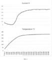
- the two-component composite induction heating susceptor prepared according to the two components and the method above exhibits a monotonic and stable current-temperature correspondence (as shown in FIG. 1 , where I 1 and I 2 are the current turning points, and the corresponding temperatures are T 1 and T 2 ).
- the temperature range defined between the temperatures corresponding to the current sudden changes i.e., the temperature range between T 1 and T 2 corresponding to I 1 and I 2
- the composite material susceptor has a maximum achievable temperature characteristic, meaning that the current and temperature will both stop increasing as shown in FIG. 1 . This characteristic provides a self-protection function for temperature regulation within the susceptor assembly.
- the present example provides a composite induction heating susceptor, which is different from Example 1 in that the mass ratio of nickel to 430 stainless-steel was 44.5:55.5.
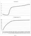
- the current-temperature correspondence curve of the susceptor of the present example obtained during electromagnetic induction heating is shown in FIG. 2 .
- the present example provides a composite induction heating susceptor, which is different from Example 1 in that nickel was replaced with 1J36 nickel alloy.
- the test results are as follows: For a single heating sheet, the current has a one-to-one correspondence with the temperature of the susceptor sheet. For different heating bodies (four randomly selected heating sheets for consistency evaluation), the heating bodies exhibit good consistency.
- the temperature deviations of different metal sheets at various currents in temperature control were within ⁇ 3°C, as shown in the table below. The temperature deviations of other examples in temperature control were also within ⁇ 3°C and are not specifically shown.
- Table 1 Set Current 1# (°C) 2# (°C) 3# (°C) 4# (°C) Consistency (temperature deviation) (°C) 2.1 201 203 202 199 201 ⁇ 2 2.15 210 213 211 209 211 ⁇ 2 2.2 221 220 223 219 221 ⁇ 2 2.25 230 233 229 227 230 ⁇ 3 2.3 240 243 241 237 240 ⁇ 3
Landscapes
- Engineering & Computer Science (AREA)
- Manufacturing & Machinery (AREA)
- Mechanical Engineering (AREA)
- Physics & Mathematics (AREA)
- Chemical & Material Sciences (AREA)
- Composite Materials (AREA)
- Materials Engineering (AREA)
- Fluid Mechanics (AREA)
- Electromagnetism (AREA)
- General Induction Heating (AREA)
- Powder Metallurgy (AREA)
Abstract
Description
- This application claims priority to
Chinese patent application No. 202210999605.0, filed on August 19, 2022 - The present application relates to the technical field of induction heating materials, in particular to a composite induction heating susceptor, preparation method thereof, and use thereof.
- Currently, a wireless temperature-controlled susceptor for induction heating an aerosol-generating substrate typically adopts a single-material stainless-steel strip or a double-layer metal foil susceptor. The double-layer metal foil susceptor is fabricated by combining a first susceptor material and a second susceptor material with different Curie temperatures, using discrete patching or multilayer bonding.
- The use of a single-material stainless-steel susceptor controlled by apparent ohmic resistance for temperature regulation has the drawback of limited temperature control precision. Moreover, since stainless-steel is an iron-based alloy with a high Curie temperature, when a single-layer stainless-steel strip is employed as a susceptor, it only functions to generate heat to form aerosol, without being able to limit the maximum temperature based on the material's inherent properties. As a result, a temperature threshold control program must be integrated into the microcontroller, which adds complexity to the structure of the induction heating device.
- In the double-layer or multi-layer metal foil susceptor, the first susceptor material is often aluminum, iron, stainless-steel, or the like, while the second susceptor material is typically nickel, a nickel alloy, etc. The temperature control logic of such a two-layer or three-layer bonded susceptor relies on the resistance-temperature curve of the susceptor, which has a minimum resistance value near the Curie temperature of the second susceptor material. By monitoring changes in this apparent resistance, the susceptor temperature can be determined, so as to achieve temperature regulation. The temperature point for the temperature control of the susceptor is determined by the Curie temperature of the second susceptor material. However, the variety of materials that can be used as the second susceptor material is limited, in which the materials whose Curie temperatures exactly meet the required temperature threshold for aerosol formation are even fewer. Therefore, this temperature control method is limited in selection of the second susceptor material. Furthermore, susceptors fabricated using physical bonding methods may suffer from issues such as uneven temperature fields, susceptor deformation, or even cracking, which can reduce the service life of the susceptor, due to differences in the physical properties of the two susceptor materials.
- Therefore, the technical problem to be solved by the present application is to overcome the limitation in selection of the second susceptor material determining the temperature point for the temperature control of the susceptor, in the double-layer or multi-layer metal foil susceptor in the prior art, and to address the issues such as uneven temperature fields, susceptor deformation, or even cracking arising from the physical bonding preparation method. In view of this, a composite induction heating susceptor, preparation method thereof, and use thereof are provided.
- In view of this, the present application provides the following technical solutions:
- The present application provides a composite induction heating susceptor, whose raw materials include a first susceptor material and a second susceptor material, which are mixed and sintered to obtain the composite induction heating susceptor.
- Optionally, the Curie temperature of the first susceptor material is in a range from 400 °C to 1000 °C.
- Optionally, the first susceptor material is at least one selected from stainless-steel, carbon steel, iron, and an iron-based alloy.
- Optionally, the Curie temperature of the second susceptor material is in a range from 200 °C to 400 °C, and preferably, is above 380 °C.
- Optionally, the second susceptor material is at least one selected from nickel, a nickel-based alloy, and an Invar alloy.
- Optionally, a mass ratio of the first susceptor material to the second susceptor material is (3 to 7) : (7 to 3).
- The present application further provides a method for preparing the composite induction heating susceptor as described above, including the following steps:
- S1: mixing the first susceptor material and the second susceptor material and slurrying to obtain a mixed slurry;
- S2: tape casting the mixed slurry to form green bodies, stacking and warm isostatic pressing the green bodies to obtain a pre-sintered body; and
- S3: de-binding and sintering the obtained pre-sintered body.
- Optionally, the warm isostatic pressing is performed at a temperature in a range from 65 °C to 85 °C for a period of time in a range from 0.1 hours (h) to 1 h at a pressure in a range from 5 MPa to 45 MPa.
- Optionally, the de-binding is performed at a temperature in a range from 250 °C to 550 °C for a period of time in a range from 1 h to 10 h; and/or
the sintering is performed at a temperature in a range from 1100 °C to 1400 °C for a period of time in a range from 0.5 h to 15 h. - The present application further provides use of the above-described composite induction heating susceptor, or the composite induction heating susceptor obtained through the above-described preparation method, in the field of electromagnetic induction heating.
- Specifically, the slurrying step in step S1 follows conventional slurry preparation processes in the field, typically by mixing metal powders with an organic solvent and a dispersant, and then ball milling the mixture. A typical, non-limiting example of the slurrying step involves uniformly mixing the first susceptor material and the second susceptor material, adding ethyl acetate, n-butanol, a 5% PVB solution, and an OP dispersant, and then ball milling the mixture in a ball mill to obtain the slurry.
- The composite induction heating susceptor provided by the present application can be in the form of sheet, tube, needle, pin, mesh, filament, granule, cup form, etc.
- The composite induction heating susceptor provided by the present application can be used in scenarios requiring temperature controlled induction heating, such as susceptor materials for induction heating in electronic cigarettes to generate aerosol, susceptor materials for medical nebulization to generate aerosol, beauty devices, and so on.
- The temperature control logic of the composite induction heating susceptor provided by the present application is as follows:
In the initial heating stage, the susceptor is heated, and the electronic controller detects an initial apparent current. As the temperature of the susceptor increases, the magnetic reluctance of the induction metal sheet increases, and correspondingly the electronic controller detects a decrease in apparent current. When the temperature of the susceptor continues to rise and approaches the Curie temperature of the low Curie temperature material in the composite induction heating susceptor, the low Curie temperature material starts to lose magnetism, resulting in a decrease in overall magnetic reluctance of the susceptor, and correspondingly the electronic controller detects a gradual increase of the apparent current. At this time, a minimum current turning point (I1) appears. In the subsequent heating stage, the electronic controller detects a one-to-one correspondence between the apparent current and the temperature of the susceptor. This one-to-one correspondence can be used to establish a standard curve for wireless temperature control. As the temperature continues to rise, the low Curie temperature material continues to lose magnetism, causing a sharp decrease in heating efficiency of the low Curie temperature material, while the magnetic reluctance of the high Curie temperature material increases with the increase of the temperature. The combined characteristics of magnetic reluctance varying with temperatures of the low and high Curie temperature materials lead to the appearance of a current turning point (I2). The currents I1 and I2 are characteristic properties of the heating element. As the current continues to increase, the electromagnetic induction heating is dominated by the high Curie temperature material. With the heating temperature continues to rise, the magnetic reluctance of the high Curie temperature material increases, which will result in current decrease. It can be understood that in the final heating stage, the high Curie temperature material heats in form of a porous framework. In other words, as the low and high Curie temperature materials are uniformly mixed, once the low Curie temperature material is fully demagnetized, only the high Curie temperature material remains to heat. By excluding the low Curie temperature material, the rest is equal to a porous "high Curie temperature material" framework. The heating efficiency of this structure sharply decreases, making the current no longer rise significantly and the temperature reach a maximum temperature, i.e., a maximum threshold temperature, thereby achieving the temperature control. The composition and ratio of different susceptor materials in the composite induction heating susceptor provided by the present application can be adjusted to regulate the standard curve and the maximum threshold temperature. - The temperature control logics in the prior art include two types:
One type involves the conventional double-layer physical bonded susceptor, which includes a first susceptor material and a second susceptor material. During the preheating period of the susceptor assembly starting from room temperature, the resistance-temperature curve (as shown inFIG. 5 , with reference to Chinese patent documentCN112739229A ) of the susceptor assembly has a minimum resistance value within a ±5 °C temperature range around the Curie temperature of the second susceptor material. This minimum resistance value is used to identify a specific temperature for temperature control. In this type of susceptor, the first susceptor material is primarily responsible for heating, while the second susceptor material acts as a temperature marker. At the Curie temperature of the second susceptor material, the magnetic properties of the second susceptor material change from ferromagnetic or ferrimagnetic to paramagnetic, accompanied by a temporary change in resistance of the material. By monitoring the corresponding current change induced by the induction source, at what time the second susceptor material reaches its Curie temperature can be detected, thus identifying at what time the second susceptor material reaches the predetermined working temperature. However, this temperature control logic can only identify the temperature point by the Curie temperature of the second susceptor material, which is limited by the material, and as there is only one temperature point, it cannot achieve temperature control over a temperature range. - The other type involves the single stainless-steel sheet susceptor. During the heating process in an induction heating device, there is a strict monotonic relationship between the temperature of the susceptor and the apparent ohmic resistance determined by the DC voltage supplied by the DC power and the DC current from the DC power. Since each single value of the apparent ohmic resistance corresponds to a unique temperature, this strict monotonic relationship allows the temperature of the susceptor to be determined based on the apparent ohmic resistance without direct contact with the induction heating device. This temperature control logic needs an obvious change in the apparent ohmic resistance of the stainless-steel sheet corresponding to temperature. In the correspondence relationship of common stainless-steel sheets, the change in apparent ohmic resistance within a given temperature range is usually too small, making the temperature control difficult to be precise.
- The technical solutions provided in the present application have the following advantages:
The composite induction heating susceptor provided by the present application is obtained by mixing the first susceptor material and the second susceptor material and then sintering the mixture. By adjusting the components and proportions of the two materials, susceptors with different temperature control ranges and Curie temperatures can be achieved, greatly enhancing the applicability of the susceptor and breaking the limitation in selection of the second susceptor material, which determines the temperature point for the susceptor temperature control. The obtained susceptor has a stable current-temperature linear relationship, and this new control logic can realize temperature control of the susceptor in electromagnetic induction heating. Moreover, the sintering process forms a single-layer composite material, achieving a susceptor with homogeneous material properties of the overall structure, ensuring that the susceptor does not deform, bend, or crack during use. The susceptor has a uniform heat distribution, and the aerosol formed is stable and consistent. - Based on the composite induction heating susceptor provided in the present application, through further limitation of the first and second susceptor materials, physical properties of the susceptor, such as thermal expansion coefficient, strength, toughness, magnetic properties, and electrical performance, can be uniformly controlled and adjusted according to application requirements, thereby broadening the application range.
- The method for preparing the composite induction heating susceptor involves evenly mixing the metallic powders of the first and second susceptor materials, slurrying the mixture, and then shaping, de-binding, and sintering the slurry according to a needed shape, thereby finally obtaining the composite induction heating susceptor. This method is simple and mature, and in post-processing (such as rolling treatment), the process is simple and easy to implement, significantly reducing manufacturing costs.
- In use of the composite induction heating susceptor provided by the present application, the composite induction heating susceptor has a monotonic and stable current-temperature curve within a specific temperature range during electromagnetic induction heating. In the stage where the current changes, the one-to-one corresponding temperature range can be used as the temperature control range of the susceptor. Additionally, the temperature of the susceptor will not increase when reaching a certain temperature even with continuous current supply, thus establishing a maximum protection temperature. By monitoring the heating current, the temperature control of the susceptor can be achieved to realize the purposed of temperature control. In the electromagnetic induction heating process, a one-to-one correspondence between the current and the temperature exists, allowing for temperature control within a specific range through the current-temperature correspondence relationship and thus ensuring high temperature control accuracy.
- In order to more clearly describe the technical solutions in the embodiments of the present application or the prior art, the drawings to be used in the description of the embodiments or the prior art will be described briefly. Apparently, the drawings described below are merely for some embodiments of the present application. For ordinary skilled persons in the art, other drawings can also be obtained based on the following drawings without creative work.
-
FIG. 1 shows a current-temperature correspondence curve of a susceptor during electromagnetic induction heating according to Example 1 of the present application. -
FIG. 2 shows a current-temperature correspondence curve of a susceptor during electromagnetic induction heating according to Example 2 of the present application. -
FIG. 3 shows a current-temperature correspondence curve of a susceptor during electromagnetic induction heating according to Example 3 of the present application. -
FIG. 4 shows a current-temperature correspondence curve of a susceptor during electromagnetic induction heating according to Example 4 of the present application. -
FIG. 5 shows a resistance-temperature curve of a susceptor prepared by conventional physical bonding, during electromagnetic induction heating. - The following examples are provided to facilitate the understanding of the present application, neither to limit the best modes nor restrict the content or protection scope of the present application. Any product, which is the same as or similar to the present application, derived from the teachings of the present application or obtained by combining the features of the present application with those of other prior art, all falls within the protection scope of the present application.
- In the examples, where specific experimental steps or conditions are not described, the processes can be carried out according to conventional experimental steps or conditions as described in literature in the field. The reagents or instruments for which manufacturers are not specified are all common products that can be purchased from the market.
- The present example provides a composite induction heating susceptor including following materials:
The two components of the susceptor were a low Curie temperature material and a high Curie temperature material. The low Curie temperature material was nickel, and the high Curie temperature material was stainless-steel. The stainless-steel can be 400-series stainless-steel, and in this example, was 430 stainless-steel. - 1) 50 g of nickel powder and 50 g of 430 stainless-steel powder were mixed, and 30 g of ethyl acetate, 20 g of n-butanol, 3 g of a 5% PVB solution, and 1 g of OP dispersant were added into the mixture. Then, the resulting mixture was put into a ball mill for 3 h of ball milling to obtain the slurry.
- 2) The slurry was tape casted into green bodies, and then the green bodies were stacked and warm isostatic pressed to obtain a single-layer pre-sintered body. The warm isostatic pressing was carried out at 75 °C for 0.5 h under the pressure of 40 MPa.
- 3) The pre-sintered body was put into a vacuum furnace for de-binding and sintering, during which the temperature was raised to 450 °C at a rate of 3 °C/min, and held at 450 °C for 60 minutes, then raised to 1250 °C at a rate of 5 °C/min, and held at 1250 °C for 30 min before the sintered body was cooled with the furnace.
- 4) The sintered body was taken out from the furnace, and cut into the desired finished susceptor.
- When heated by electromagnetic induction (with an electromagnetic heating frequency of 6.78 MHz), the two-component composite induction heating susceptor prepared according to the two components and the method above exhibits a monotonic and stable current-temperature correspondence (as shown in
FIG. 1 , where I1 and I2 are the current turning points, and the corresponding temperatures are T1 and T2). The temperature range defined between the temperatures corresponding to the current sudden changes (i.e., the temperature range between T1 and T2 corresponding to I1 and I2) can be used as the temperature control range of the susceptor. Additionally, the composite material susceptor has a maximum achievable temperature characteristic, meaning that the current and temperature will both stop increasing as shown inFIG. 1 . This characteristic provides a self-protection function for temperature regulation within the susceptor assembly. - The present example provides a composite induction heating susceptor, which is different from Example 1 in that the mass ratio of nickel to 430 stainless-steel was 44.5:55.5.
- The current-temperature correspondence curve of the susceptor of the present example obtained during electromagnetic induction heating is shown in
FIG. 2 . - The present example provides a composite induction heating susceptor, which is different from Example 1 in that 430 stainless-steel was replaced with 420 stainless-steel.
- The current-temperature correspondence curve of the susceptor of the present example obtained during electromagnetic induction heating is shown in
FIG. 3 . - The present example provides a composite induction heating susceptor, which is different from Example 1 in that nickel was replaced with 1J36 nickel alloy.
- The current-temperature correspondence curve of the susceptor of the present example obtained during electromagnetic induction heating is shown in
FIG. 4 . - The heating body provided in Example 2 of the present application was tested, with the following procedure:
- Step 1: the prepared induction metal sheet was cut into standard sizes of 8.6 mm in width and 16 mm in length.
- Step 2: a thermocouple was attached to the standard sized metal sheet to measure the temperature.
- Step 3: the induction heating sheet with the attached thermocouple was secured at the center of an electromagnetic induction heating coil.
- Step 4: the voltage of the coil was set to 7.8 V, and the current of the coil was respectively set to 2.1 A, 2.15 A, 2.2 A, 2.25 A, and 2.3 A, and stable temperatures of the thermocouple at different currents were recorded. Each stable temperature was measured after 60 seconds of heating.
- Step 5:
steps 1 to 4 were repeated to test four heating sheets, and the consistency of the heating sheets was evaluated. - The test results are as follows: For a single heating sheet, the current has a one-to-one correspondence with the temperature of the susceptor sheet. For different heating bodies (four randomly selected heating sheets for consistency evaluation), the heating bodies exhibit good consistency. The temperature deviations of different metal sheets at various currents in temperature control were within ±3°C, as shown in the table below. The temperature deviations of other examples in temperature control were also within ±3°C and are not specifically shown.
Table 1 Set Current 1# (°C) 2# (°C) 3# (°C) 4# (°C) Consistency (temperature deviation) (°C) 2.1 201 203 202 199 201±2 2.15 210 213 211 209 211±2 2.2 221 220 223 219 221±2 2.25 230 233 229 227 230±3 2.3 240 243 241 237 240±3 - From the current-temperature correspondence curves obtained in the above examples, it can be seen that according to the composite induction heating susceptor provided by the present application, through adjusting and adapting the components and proportions of the two materials, susceptors with different temperature control ranges and Curie temperatures can be achieved, greatly enhancing the applicability of the susceptor and breaking the limitation in selection of the second susceptor material, which determines the temperature point for the susceptor temperature control.
- Clearly, the above examples are only provided for the purpose of illustrating and are not intended to limit the implementation. For those skilled in the art, other variations or modifications can be made based on the above description. It is neither necessary nor possible to enumerate all possible embodiments. Any obvious modifications or variations derived from the above are all within the protection scope of the present invention.
Claims (10)
- A composite induction heating susceptor, whose raw materials comprise a first susceptor material and a second susceptor material, which are mixed and sintered to obtain the composite induction heating susceptor.
- The composite induction heating susceptor according to claim 1, wherein a Curie temperature of the first susceptor material is in a range from 400 °C to1000 °C.
- The composite induction heating susceptor according to claim 2, wherein the first susceptor material is selected from the group consisting of stainless-steel, carbon steel, iron, an iron-based alloy, and any combination thereof.
- The composite induction heating susceptor according to claim 1, wherein a Curie temperature of the second susceptor material is in a range from 200 °C to 400 °C, and preferably, is above 380 °C.
- The composite induction heating susceptor according to claim 4, wherein the second susceptor material is selected from the group consisting of nickel, a nickel-based alloy, an Invar alloy, and any combination thereof.
- The composite induction heating susceptor according to any one of claims 1 to 5, wherein a mass ratio of the first susceptor material to the second susceptor material is (3 to 7) : (7 to 3).
- A method for preparing the composite induction heating susceptor according to any one of claims 1 to 6, comprising:S1: mixing the first susceptor material and the second susceptor material and slurrying to obtain a mixed slurry;S2: tape casting the mixed slurry to form green bodies, stacking and warm isostatic pressing the green bodies to obtain a pre-sintered body; andS3: de-binding and sintering the obtained pre-sintered body.
- The method according to claim 7, wherein the warm isostatic pressing is performed at a temperature in a range from 65 °C to 85 °C for a period of time in a range from 0.1 h to 1 h at a pressure in a range from 5 MPa to 45 MPa.
- The method according to claim 7, wherein the de-binding is performed at a temperature in a range from 250 °C to 550 °C for a period of time in a range from 1 h to 10 h; and/or the sintering is performed at a temperature in a range from 1100 °C to 1400 °C for a period of time in a range from 0.5 h to 15 h.
- Use of the composite induction heating susceptor according to any one of claims 1 to 6 or the composite induction heating susceptor prepared by the method according to any one of claims 7 to 9 in the field of electromagnetic induction heating.
Applications Claiming Priority (2)
| Application Number | Priority Date | Filing Date | Title |
|---|---|---|---|
| CN202210999605.0A CN115191670B (en) | 2022-08-19 | 2022-08-19 | Composite induction heating susceptor and preparation method and application thereof |
| PCT/CN2023/093579 WO2024037065A1 (en) | 2022-08-19 | 2023-05-11 | Composite induction heating susceptor, preparation method therefor and use thereof |
Publications (2)
| Publication Number | Publication Date |
|---|---|
| EP4533968A1 true EP4533968A1 (en) | 2025-04-09 |
| EP4533968A4 EP4533968A4 (en) | 2025-10-29 |
Family
ID=83572126
Family Applications (1)
| Application Number | Title | Priority Date | Filing Date |
|---|---|---|---|
| EP23853972.0A Pending EP4533968A4 (en) | 2022-08-19 | 2023-05-11 | COMPOSITE INDUCTION HEATING SUSCEPTOR, MANUFACTURING METHOD FOR IT AND USE OF IT |
Country Status (3)
| Country | Link |
|---|---|
| EP (1) | EP4533968A4 (en) |
| CN (2) | CN120982808A (en) |
| WO (1) | WO2024037065A1 (en) |
Families Citing this family (5)
| Publication number | Priority date | Publication date | Assignee | Title |
|---|---|---|---|---|
| CN120982808A (en) * | 2022-08-19 | 2025-11-21 | 深圳麦克韦尔科技有限公司 | A composite induction heating sensor, its preparation method and application |
| CN116172274A (en) * | 2022-12-16 | 2023-05-30 | 沃德韦国际控股有限公司 | Temperature control method, device and aerosol generating device of aerosol generating device |
| WO2024124554A1 (en) * | 2022-12-16 | 2024-06-20 | 沃德韦国际控股有限公司 | Temperature control method and apparatus for aerosol generating apparatus, and aerosol generating device |
| CN116491712B (en) * | 2023-03-07 | 2025-10-17 | 深圳市飞雾科技有限公司 | Susceptor, method of manufacturing the same, and aerosol article |
| EP4710779A1 (en) * | 2023-05-12 | 2026-03-18 | Shenzhen Huabao Collaborative Innovation Technology Research Institute Co. Ltd | Aerosol generating product |
Family Cites Families (14)
| Publication number | Priority date | Publication date | Assignee | Title |
|---|---|---|---|---|
| US6884976B2 (en) * | 2002-11-27 | 2005-04-26 | The Boeing Company | Induction heating for localized joining of structural members |
| CN101367649B (en) * | 2008-10-13 | 2011-08-24 | 电子科技大学 | A kind of zinc oxide varistor dielectric material and resistor preparation method |
| GB2504730B (en) * | 2012-08-08 | 2015-01-14 | Reckitt & Colman Overseas | Device for evaporating a volatile fluid |
| TWI664918B (en) * | 2014-05-21 | 2019-07-11 | 瑞士商菲利浦莫里斯製品股份有限公司 | Inductively heatable tobacco product |
| TWI635897B (en) * | 2014-05-21 | 2018-09-21 | 瑞士商菲利浦莫里斯製品股份有限公司 | Aerosol-forming substrate and aerosol-delivery system |
| AR111392A1 (en) * | 2017-03-31 | 2019-07-10 | Philip Morris Products Sa | SUSCEPTING UNIT TO HEAT BY INDUCTION AN AEROSOL FORMER SUBSTRATE |
| AR111347A1 (en) * | 2017-03-31 | 2019-07-03 | Philip Morris Products Sa | MULTI-PAPER SUSCEPTOR UNIT TO HEAT BY INDUCTION AN AEROSOL FORMER SUBSTRATE |
| GB201809786D0 (en) * | 2018-06-14 | 2018-08-01 | Nicoventures Trading Ltd | Induction heating system and heater |
| US12063970B2 (en) | 2018-09-25 | 2024-08-20 | Philip Morris Products S.A. | Inductive heating assembly for inductive heating of an aerosol-forming substrate |
| CN210726703U (en) * | 2019-08-14 | 2020-06-12 | 湖南中烟工业有限责任公司 | Heating element with porous heat-insulating layer and low-temperature smoking set |
| AU2021286189A1 (en) * | 2020-06-05 | 2022-12-15 | Philip Morris Products S.A. | Susceptor assembly comprising one or more composite susceptor particles |
| CN113967738B (en) * | 2020-07-24 | 2024-05-24 | 四川三联新材料有限公司 | Aerosol generating device, sensor and preparation method |
| CN116634896A (en) * | 2020-12-23 | 2023-08-22 | 菲利普莫里斯生产公司 | Aerosol generating device and system including induction heating device and method of operation thereof |
| CN120982808A (en) * | 2022-08-19 | 2025-11-21 | 深圳麦克韦尔科技有限公司 | A composite induction heating sensor, its preparation method and application |
-
2022
- 2022-08-19 CN CN202511394759.7A patent/CN120982808A/en active Pending
- 2022-08-19 CN CN202210999605.0A patent/CN115191670B/en active Active
-
2023
- 2023-05-11 WO PCT/CN2023/093579 patent/WO2024037065A1/en not_active Ceased
- 2023-05-11 EP EP23853972.0A patent/EP4533968A4/en active Pending
Also Published As
| Publication number | Publication date |
|---|---|
| WO2024037065A1 (en) | 2024-02-22 |
| CN115191670B (en) | 2025-10-31 |
| EP4533968A4 (en) | 2025-10-29 |
| CN120982808A (en) | 2025-11-21 |
| CN115191670A (en) | 2022-10-18 |
Similar Documents
| Publication | Publication Date | Title |
|---|---|---|
| CN115191670B (en) | Composite induction heating susceptor and preparation method and application thereof | |
| EP4533969A1 (en) | Multi-layer induction heating body, preparation method therefor and use thereof | |
| US20230135881A1 (en) | Electromagnetic induction heating element and electromagnetic induction heating element assembly | |
| WO2020151597A1 (en) | Cigarette heating assembly and electric heating smoking device | |
| TWI424455B (en) | Laminated ceramic electronic parts and manufacturing method thereof | |
| US6660412B2 (en) | Low loss, high frequency composite magnetic material and methods of making the same | |
| TWI486321B (en) | Ferrite ceramic composition, ceramic electronic component, and process for producing ceramic electronic component | |
| TWI587323B (en) | Manufacturing method of NTC thermal resistance device | |
| US9862163B2 (en) | Sintered boron nitride body and method for producing a sintered boron nitride body | |
| WO2023029660A1 (en) | Electromagnetic induction heating layer and preparation method therefor, and atomization core and preparation method therefor | |
| CN112876232A (en) | High-temperature NTC thermal sensitive ceramic material and discharge plasma sintering method thereof | |
| JPWO2012173147A1 (en) | Multilayer coil component and method for manufacturing the multilayer coil component | |
| WO2016072428A1 (en) | Laminated coil component | |
| CN221996914U (en) | Multilayer induction heating body | |
| CN104671746B (en) | A kind of thermistor potsherd, thermistor and preparation method thereof | |
| CN106278226A (en) | A kind of preparation method of ternary system negative temperature coefficient heat-sensitive resistance material | |
| US6146550A (en) | Electrical resistance heating element for an electric furnace and process for manufacturing such a resistance element | |
| CN116944493A (en) | Metal slurry, heating element with concave-convex surface and aerosol generator | |
| JP2009215152A (en) | Sintered ferrite material | |
| CN108264344A (en) | A kind of nanocrystalline barium titanate barium thermal sensitive ceramics and preparation method thereof | |
| JP2000299180A (en) | Manufacturing method of ceramic heater | |
| WO2013021885A1 (en) | Method of manufacturing ceramic electronic part | |
| CN107871574A (en) | A kind of manufacture method of negative temperature coefficient ceramics thermistor | |
| JP2023136387A (en) | High resistance/high corrosion resistance ceramic material and wafer mounting table | |
| JPH04174505A (en) | Laminate type inductor and manufacture |
Legal Events
| Date | Code | Title | Description |
|---|---|---|---|
| STAA | Information on the status of an ep patent application or granted ep patent |
Free format text: STATUS: THE INTERNATIONAL PUBLICATION HAS BEEN MADE |
|
| PUAI | Public reference made under article 153(3) epc to a published international application that has entered the european phase |
Free format text: ORIGINAL CODE: 0009012 |
|
| STAA | Information on the status of an ep patent application or granted ep patent |
Free format text: STATUS: REQUEST FOR EXAMINATION WAS MADE |
|
| 17P | Request for examination filed |
Effective date: 20241230 |
|
| AK | Designated contracting states |
Kind code of ref document: A1 Designated state(s): AL AT BE BG CH CY CZ DE DK EE ES FI FR GB GR HR HU IE IS IT LI LT LU LV MC ME MK MT NL NO PL PT RO RS SE SI SK SM TR |
|
| REG | Reference to a national code |
Ref country code: DE Ref legal event code: R079 Free format text: PREVIOUS MAIN CLASS: A24F0040465000 Ipc: H05B0006100000 |
|
| A4 | Supplementary search report drawn up and despatched |
Effective date: 20250929 |
|
| RIC1 | Information provided on ipc code assigned before grant |
Ipc: H05B 6/10 20060101AFI20250923BHEP Ipc: A24F 40/465 20200101ALI20250923BHEP Ipc: A24F 40/70 20200101ALI20250923BHEP Ipc: A24F 40/40 20200101ALI20250923BHEP Ipc: B22F 3/22 20060101ALI20250923BHEP Ipc: B22F 3/14 20060101ALI20250923BHEP Ipc: B22F 7/02 20060101ALI20250923BHEP Ipc: B22F 3/10 20060101ALI20250923BHEP Ipc: B22F 5/00 20060101ALI20250923BHEP |
|
| DAV | Request for validation of the european patent (deleted) | ||
| DAX | Request for extension of the european patent (deleted) |