EP4531507A1 - Uninterrupted power supply - Google Patents
Uninterrupted power supply Download PDFInfo
- Publication number
- EP4531507A1 EP4531507A1 EP24178952.8A EP24178952A EP4531507A1 EP 4531507 A1 EP4531507 A1 EP 4531507A1 EP 24178952 A EP24178952 A EP 24178952A EP 4531507 A1 EP4531507 A1 EP 4531507A1
- Authority
- EP
- European Patent Office
- Prior art keywords
- copper bar
- bypass
- cabinet
- area
- vertical
- Prior art date
- Legal status (The legal status is an assumption and is not a legal conclusion. Google has not performed a legal analysis and makes no representation as to the accuracy of the status listed.)
- Pending
Links
- 238000012423 maintenance Methods 0.000 claims abstract description 14
- 238000012544 monitoring process Methods 0.000 claims abstract description 9
- RYGMFSIKBFXOCR-UHFFFAOYSA-N Copper Chemical compound [Cu] RYGMFSIKBFXOCR-UHFFFAOYSA-N 0.000 claims description 334
- 229910052802 copper Inorganic materials 0.000 claims description 334
- 239000010949 copper Substances 0.000 claims description 334
- 230000007935 neutral effect Effects 0.000 claims description 14
- 238000010586 diagram Methods 0.000 description 5
- 230000006978 adaptation Effects 0.000 description 2
- 230000009286 beneficial effect Effects 0.000 description 2
- 238000012986 modification Methods 0.000 description 2
- 230000004048 modification Effects 0.000 description 2
- 239000000470 constituent Substances 0.000 description 1
- 238000005457 optimization Methods 0.000 description 1
Images



Classifications
-
- H—ELECTRICITY
- H05—ELECTRIC TECHNIQUES NOT OTHERWISE PROVIDED FOR
- H05K—PRINTED CIRCUITS; CASINGS OR CONSTRUCTIONAL DETAILS OF ELECTRIC APPARATUS; MANUFACTURE OF ASSEMBLAGES OF ELECTRICAL COMPONENTS
- H05K7/00—Constructional details common to different types of electric apparatus
- H05K7/14—Mounting supporting structure in casing or on frame or rack
- H05K7/1422—Printed circuit boards receptacles, e.g. stacked structures, electronic circuit modules or box like frames
- H05K7/1427—Housings
- H05K7/1432—Housings specially adapted for power drive units or power converters
- H05K7/14325—Housings specially adapted for power drive units or power converters for cabinets or racks
-
- H—ELECTRICITY
- H05—ELECTRIC TECHNIQUES NOT OTHERWISE PROVIDED FOR
- H05K—PRINTED CIRCUITS; CASINGS OR CONSTRUCTIONAL DETAILS OF ELECTRIC APPARATUS; MANUFACTURE OF ASSEMBLAGES OF ELECTRICAL COMPONENTS
- H05K7/00—Constructional details common to different types of electric apparatus
- H05K7/14—Mounting supporting structure in casing or on frame or rack
- H05K7/1485—Servers; Data center rooms, e.g. 19-inch computer racks
- H05K7/1488—Cabinets therefor, e.g. chassis or racks or mechanical interfaces between blades and support structures
- H05K7/1492—Cabinets therefor, e.g. chassis or racks or mechanical interfaces between blades and support structures having electrical distribution arrangements, e.g. power supply or data communications
Definitions
- the present application relates to the field of power systems, and in particular to an uninterrupted power supply.
- the fierce competition in the market requires continuous optimization of the power systems, which includes increasing the power density, i.e., providing more power output in the same physical space to meet continuously growing power requirements. Meanwhile, it is also necessary to reduce the costs of arrangement to improve competitiveness.
- the reduction in floor space is an important goal, especially when power systems are deployed in a limited space. This may require utilizing a more compact, efficient uninterrupted power supply to minimize the physical size of the system.
- a power density of the uninterrupted power supply needs to be continuously increased. This means that an uninterrupted power supply can provide more power output while maintaining a relatively small size, which is very important for applications with high power requirements.
- the market also places higher requirements on the reliability of uninterrupted power supply products. The reliability means that the uninterrupted power supply must be able to operate stably during power interruption to protect critical equipment from power interruption.
- the technical problem to be solved by the present disclosure is to provide an uninterrupted power supply which can, while meeting high power density, maximally improve the reliability of a product through innovative layout, and meanwhile can greatly reduce floor space and satisfy the market's requirements for arrangement costs of uninterrupted power supply equipment on the basis of existing corresponding power equipment.
- an uninterrupted power supply comprising: a cabinet, comprising a wiring area and a module area disposed in parallel along a width direction of the cabinet; an output area, a maintenance switch area, a bypass input area, and a main input area disposed in a vertical direction in the wiring area; a first power module, a monitoring module, a bypass module, and a second power module disposed in a vertical direction in the module area.
- the uninterrupted power supply further comprises a control wire inlet, which is also disposed in the module area.
- control wire inlet, the first power module, the monitoring module, the bypass module, and the second power module are sequentially stacked in a vertical direction.
- the output area, the maintenance switch area, the bypass input area, and the main input area are sequentially stacked in a vertical direction.
- the output area and the maintenance switch area is opposite to the first power module in a horizontal direction.
- an output copper bar assembly which comprises a first horizontal output copper bar, a second horizontal output copper bar, a third horizontal output copper bar, a first vertical output copper bar, a second vertical output copper bar, and a third vertical output copper bar; the first horizontal output copper bar, the second horizontal output copper bar, and the third horizontal output copper bar are disposed in the output area; the first vertical output copper bar, the second vertical output copper bar and the third vertical output copper bar are disposed on a side wall of the cabinet that is close to the module area; the first horizontal output copper bar, the second horizontal output copper bar and the third horizontal output copper bar are fixedly connected together with the first vertical output copper bar, the second vertical output copper bar, and the third vertical output copper bar respectively.
- first horizontal output copper bar, the second horizontal output copper bar, and the third horizontal output copper bar extend along a depth direction of the cabinet and are arranged in parallel along a width direction of the cabinet; the first vertical output copper bar, the second vertical output copper bar and the third vertical output copper bar extend along a height direction of the cabinet and are arranged in parallel along the depth direction of the cabinet.
- a horizontal neutral wire copper bar and a vertical neutral wire copper bar the horizontal neutral wire copper bar extending along the depth direction of the cabinet and arranged in parallel to the first horizontal output copper bar, the second horizontal output copper bar and the third horizontal output copper bar along the width direction of the cabinet; the vertical neutral wire copper bar extending along the height direction of the cabinet.
- ground copper bar which is disposed above the first horizontal output copper bar and extends along the depth direction of the cabinet.
- the bypass input area is opposite to the bypass module in a horizontal direction.
- bypass copper bar assembly which comprises a first bypass copper bar, a second bypass copper bar, a third bypass copper bar, a fourth bypass copper bar, a fifth bypass copper bar and a sixth bypass copper bar; the first bypass copper bar, the second bypass copper bar and the third bypass copper bar are disposed in the bypass input area; the fourth bypass copper bar, the fifth bypass copper bar, and the sixth bypass copper bar are disposed in the module area; the first bypass copper bar, the second bypass copper bar and the third bypass copper bar are fixedly connected together with the fourth bypass copper bar, the fifth bypass copper bar and the sixth bypass copper bar respectively.
- first bypass copper bar, the second bypass copper bar, and the third bypass copper bar extend along the depth direction of the cabinet and are arranged in parallel along the width direction of the cabinet; the fourth bypass copper bar, the fifth bypass copper bar, and the sixth bypass copper bar extend along the width direction of the cabinet and are arranged in parallel along the height direction of the cabinet.
- bypass module is fixedly connected together with the fourth bypass copper bar, the fifth bypass copper bar, and the sixth bypass copper bar
- an output end of the bypass module is fixedly connected together with the first vertical output copper bar, the second vertical output copper bar and the third vertical output copper bar.
- the main input area is opposite to the second power module in a horizontal direction.
- a main copper bar assembly which comprises a first horizontal main copper bar, a second horizontal main copper bar, a third horizontal main copper bar, a first vertical main copper bar, a second vertical main copper bar, and a third vertical main copper bar; the first horizontal main copper bar, the second horizontal main copper bar and the third horizontal main copper bar are disposed in the main input area; the first vertical main copper bar, the second vertical main copper bar and the third vertical main copper bar are disposed between the wiring area and the module area.
- first horizontal main copper bar, the second horizontal main copper bar and the third horizontal main copper bar extend along the depth direction of the cabinet and are arranged in parallel along the width direction of the cabinet; the first vertical main copper bar, the second vertical main copper bar and the third vertical main copper bar extend along the height direction of the cabinet and are arranged in parallel along the depth direction of the cabinet.
- a battery wiring assembly comprising a first anode wiring copper bar, a first cathode wiring copper bar, a second anode wiring copper bar and a second cathode wiring copper bar, the first anode wiring copper bar and the first cathode wiring copper bar are disposed above the output area; the second anode wiring copper bar and the second cathode wiring copper bar are disposed between the wiring area and the module area Further, the first anode wiring copper bar and the first cathode wiring copper bar extend along the depth direction of the cabinet and are arranged in parallel along the height direction of the cabinet; the second anode wiring copper bar and the second cathode wiring copper bar extend along the height direction of the cabinet and are arranged in parallel along the depth direction of the cabinet.
- a top and a bottom of the cabinet are provided with an upper wire inlet and a lower wire inlet, respectively, the upper wire inlet and the lower wire inlet being disposed on the same side of the cabinet as the output area, maintenance switch area, the bypass input area and the main input area.
- the beneficial effects of the present disclosure are: the uninterrupted power supply of the present disclosure, while meeting high power density, maximally improves the reliability of a product through innovative layout; meanwhile optimizes the overall layout, greatly reduces floor space and satisfies the market's requirements for arrangement costs of uninterrupted power supply equipment on the basis of existing corresponding power equipment; and can realize a multi-scenario configuration of an uninterrupted power supply, with flexible configuration, fast and convenient on-site deployment, and adaptation to on-site requirements of customers.
- the reference symbols include: 100 cabinet 110 output area 120 maintenance switch area 130 bypass input area 140 main input area 150 control wire inlet 160 upper wire inlet 170 lower wire inlet 180 wiring area 190 module area 200 monitoring module 300 bypass module 400 second power module 500 first power module m main copper bar assembly mA1 first horizontal main copper bar mB1 second horizontal main copper bar mC1 third horizontal main copper bar mA2 first vertical main copper bar mB2 second vertical main copper bar mC2 third vertical main copper bar b bypass copper bar assembly bA1 first bypass copper bar bB 1 second bypass copper bar bC1 third bypass copper bar bA2 fourth bypass copper bar bB2 fifth bypass copper bar bC2 sixth bypass copper bar o output copper bar assembly oA1 first output copper bar oB1 second horizontal output copper bar oC1 third horizontal output copper bar N1 horizontal neutral wire copper bar PE ground copper bar 520 battery wiring assembly 521 first anode wiring copper bar 522 first cathode wiring copper bar 523 second anode wiring copper bar 524 second cath
- first and second are used only to describe purposes, but cannot be construed as indicating or implying relative importance or implicitly indicating the number of technical features as indicated. Accordingly, a feature limited by “first” and “second” can explicitly or implicitly include one or more that feature. In the description of the present disclosure, “multiple” means two or more, unless otherwise defined specifically.
- the uninterrupted power supply comprises: a cabinet 100 comprising a wiring area 180 and a module area 190 disposed in parallel along a width direction of the cabinet 100; an output area 110, a maintenance switch area 120, a bypass input area 130, and a main input area 140 disposed in the wiring area 180 along a vertical direction; a first power module 500, a monitoring module 200, a bypass module 300 and a second power module 400 disposed in the module area 190 along a vertical direction.
- the uninterrupted power supply of the present disclosure while meeting high power density, maximally improves the reliability of a product through innovative layout, at the same time, it optimizes the overall layout, greatly reduces floor space and satisfies the market's requirements for arrangement costs of uninterrupted power supply equipment on the basis of existing corresponding power equipment; and can realize a multi-scenario configuration of an uninterrupted power supply, with flexible configuration, fast and convenient on-site deployment, and adaptation to on-site requirements of customers.
- the above-mentioned respective constituent parts will be further introduced below in detail, respectively.
- the cabinet 100 is generally in the shape of a rectangular box, which is divided into a wiring area 180 for convenient wiring and a module area 190 installed with multiple modules.
- the wiring area 180 and the module area 190 are disposed in parallel along a width direction of the cabinet 100, that is, the wiring area 180 is disposed on one side inside the cabinet 100, and the module area 190 is disposed on the other side inside the cabinet 100.
- An upper wire inlet 160 and a lower wire inlet 170 are disposed at the top and bottom of the cabinet 100 respectively, and the upper wire inlet 160 and the lower wire inlet 170 are disposed on the same side of the cabinet 100 as the wiring area 180, that is, the upper wire inlet 160 and the lower wire inlet 170 are disposed in the wiring area 180.
- the wiring area 180 may specifically comprise an output area 110, a maintenance switch area 120, a bypass input area 130 and a main input area 140.
- the output area 110, the maintenance switch area 120, the bypass input area 130 and the main input area 140 are sequentially stacked in the wiring area 180 of the cabinet 100 along a vertical direction from top to bottom.
- the module area 190 may specifically comprise a control wire inlet 150, a first power module 500, a monitoring module 200, a bypass module 300 and a second power module 400.
- the control wire inlet 150 together with the first power module 500, the monitoring module 200, the bypass module 300 and the second power module 400 are sequentially stacked in the module area 190 of the cabinet 100 along a vertical direction from top to bottom.
- There can be multiple first power modules 500 and multiple second power modules 400 wherein multiple first power modules 500 are stacked together along the vertical direction, and multiple second power modules 400 are also stacked together along the vertical direction.
- the first power module 500 is opposite to the output area 110 and the maintenance switch area 120 in a horizontal direction
- the bypass module 300 is opposite to the bypass input area 130 in the horizontal direction
- the second power module 400 is opposite to the main input area 140 in the horizontal direction.
- the uninterrupted power supply further comprises an output copper bar assembly o.
- the output copper bar assembly o comprises a first horizontal output copper bar oA1, a second horizontal output copper bar oB 1, a third horizontal output copper bar oC1, a first vertical output copper bar oA2, a second vertical output copper bar oB2 and a third vertical output copper bar oC2.
- the first horizontal output copper bar oA1, the second horizontal output copper bar oB 1 and the third horizontal output copper bar oC1 are fixedly connected together with the first vertical output copper bar oA2, the second vertical output copper bar oB2 and the third vertical output copper bar oC2 respectively.
- the first vertical output copper bar oA2, the second vertical output copper bar oB2 and the third vertical output copper bar oC2 are disposed on a side wall of the cabinet 100 that is close to the module area 190.
- the first vertical output copper bar oA2, the second vertical output copper bar oB2 and the third vertical output copper bar oC2 extend along a height direction of the cabinet 100, that is, the length direction of each of the first vertical output copper bar oA2, the second vertical output copper bar oB2 and the third vertical output copper bar oC2 is the same as the height direction of the cabinet 100.
- the first vertical output copper bar oA2, the second vertical output copper bar oB2 and the third vertical output copper bar oC2 are disposed in parallel to each other and are arranged along the depth direction of the cabinet 100.
- the uninterrupted power supply further comprises a horizontal neutral wire copper bar N1 and a vertical neutral wire copper bar N2.
- the horizontal neutral wire copper bar N1 extends along the depth direction of the cabinet 100, and is arranged in parallel to the first horizontal output copper bar oA1, the second horizontal output copper bar oB1 and the third horizontal output copper bar oC1 along the width direction of the cabinet 100.
- the vertical neutral wire copper bar N2 is disposed between the wiring area 180 and the module area 190, and it extends along the height direction of the cabinet 100.
- the uninterrupted power supply further comprises a ground copper bar PE.
- the ground copper bar PE is disposed above the first horizontal output copper bar oA1 and extends along the depth direction of the cabinet 100.
- the uninterrupted power supply further comprises a bypass copper bar assembly b.
- the bypass copper bar assembly b comprises a first bypass copper bar bA1, a second bypass copper bar bB1, a third bypass copper bar bC1, a fourth bypass copper bar bA2, a fifth bypass copper bar bB2 and a sixth bypass copper bar bC2.
- the fourth bypass copper bar bA2, the fifth bypass copper bar bB2 and the sixth bypass copper bar are fixedly connected together with the first bypass copper bar bA1, the second bypass copper bar bB1 and the third bypass copper bar bC1 respectively.
- the first bypass copper bar bA1, the second bypass copper bar bB1 and the third bypass copper bar bC1 are disposed in the bypass input area 130.
- the first bypass copper bar bA1, the second bypass copper bar bB1 and the third bypass copper bar bC1 extend along the depth direction of the cabinet 100 and are arranged in parallel along the width direction of the cabinet 100.
- the fourth bypass copper bar bA2, the fifth bypass copper bar bB2 and the sixth bypass copper bar bC2 are disposed in the module area 190.
- the fourth bypass copper bar bA2, the fifth bypass copper bar bB2 and the sixth bypass copper bar bC2 extend along the width direction of the cabinet 100 and are arranged in parallel along the height direction of the cabinet 100.
- the uninterrupted power supply further comprises a main copper bar assembly m.
- the main copper bar assembly m comprises a first horizontal main copper bar mA1, a second horizontal main copper bar mB 1, a third horizontal main copper bar mC1, a first vertical main copper bar mA2, a second vertical main copper bar mB2 and a third vertical main copper bar mC2.
- the first horizontal main copper bar mA1, the second horizontal main copper bar mB 1 and the third horizontal main copper bar mC1 are disposed in the main input area 140.
- the first horizontal main copper bar mA1, the second horizontal main copper bar mB 1 and the third horizontal main copper bar mC1 extend along the depth direction of the cabinet 100 and are arranged in parallel along the width direction of the cabinet 100.
- the first vertical main copper bar mA2, the second vertical main copper bar mB2 and the third vertical main copper bar mC2 are disposed between the wiring area 180 and the module area 190.
- the first vertical main copper bar mA2, the second vertical main copper bar mB2 and the third vertical main copper bar mC2 extend along the height direction of the cabinet 100 and are arranged in parallel along the depth direction of the cabinet 100.
- the uninterrupted power supply further comprises a battery wiring assembly 520.
- the battery wiring assembly 520 comprises a first anode wiring copper bar 521, a first cathode wiring copper bar 522, a second anode wiring copper bar 523 and a second cathode wiring copper bar 524.
- the first anode wiring copper bar 521 and the first cathode wiring copper bar 522 are disposed above the output area 110.
- the first anode wiring copper bar 521 and the first cathode wiring copper bar 522 extend along the depth direction of the cabinet 100 and are arranged in parallel along the height direction of the cabinet.
- the second anode wiring copper bar 523 and the second cathode wiring copper bar 524 are disposed between the wiring area 180 and the module area 190.
- the second anode wiring copper bar 523 and the second cathode wiring copper bar 524 extend along the height direction of the cabinet 100 and are arranged in parallel along the depth direction of the cabinet 100.
- the layout of various modules and copper bars of the switchless uninterrupted power supply is proper, convenient, and safe for wiring; the layout of the main copper bar assembly m, the output copper bar assembly o, the bypass copper bar assembly b, the neutral wire copper bar N, the ground copper bar PE and the battery wiring assembly 520 improves the reliability of the system and the current sharing capacity of equipment.
Landscapes
- Engineering & Computer Science (AREA)
- Microelectronics & Electronic Packaging (AREA)
- Computer Hardware Design (AREA)
- General Engineering & Computer Science (AREA)
- Patch Boards (AREA)
- Stand-By Power Supply Arrangements (AREA)
Abstract
The present disclosure provides an uninterrupted power supply, comprising: a cabinet comprising a wiring area and a module area disposed in parallel along a width direction of the cabinet; an output area, a maintenance switch area, a bypass input area and a main input area disposed in the wiring area along a vertical direction; a first power module, a monitoring module, a bypass module and a second power module disposed in the module area along a vertical direction. The uninterrupted power supply of the present disclosure, while meeting high power density, improves the reliability of a product maximally through innovative layout; meanwhile optimizes the overall layout, greatly reduces floor space and meets the market's requirements for costs for arrangement of uninterrupted power supply equipment on the basis of existing corresponding power equipment; and can realize a multi-scenario configuration of an uninterrupted power supply, with flexible configuration, fast and convenient on-site deployment, which is appropriate for customer's on-site requirements.
Description
- The present application relates to the field of power systems, and in particular to an uninterrupted power supply.
- The fierce competition in the market requires continuous optimization of the power systems, which includes increasing the power density, i.e., providing more power output in the same physical space to meet continuously growing power requirements. Meanwhile, it is also necessary to reduce the costs of arrangement to improve competitiveness. The reduction in floor space is an important goal, especially when power systems are deployed in a limited space. This may require utilizing a more compact, efficient uninterrupted power supply to minimize the physical size of the system. With the continuous advancements in technology, a power density of the uninterrupted power supply needs to be continuously increased. This means that an uninterrupted power supply can provide more power output while maintaining a relatively small size, which is very important for applications with high power requirements. In addition to increasing power density, the market also places higher requirements on the reliability of uninterrupted power supply products. The reliability means that the uninterrupted power supply must be able to operate stably during power interruption to protect critical equipment from power interruption.
- In summary, the market for power system and uninterrupted power supply is facing multiple challenges and opportunities. The key goals are continuously to increase power density, reduce floor space, and improve reliability, which require continuous innovation and technological advancements to meet market requirements, reduce product costs, and improve performance. This trend will help to meet continuously growing requirements for power systems in different industries and application fields.
- The technical problem to be solved by the present disclosure is to provide an uninterrupted power supply which can, while meeting high power density, maximally improve the reliability of a product through innovative layout, and meanwhile can greatly reduce floor space and satisfy the market's requirements for arrangement costs of uninterrupted power supply equipment on the basis of existing corresponding power equipment.
- To solve the above-mentioned technical problem, a technical solution provided by the present disclosure is: an uninterrupted power supply, comprising: a cabinet, comprising a wiring area and a module area disposed in parallel along a width direction of the cabinet; an output area, a maintenance switch area, a bypass input area, and a main input area disposed in a vertical direction in the wiring area; a first power module, a monitoring module, a bypass module, and a second power module disposed in a vertical direction in the module area.
- Further, the uninterrupted power supply further comprises a control wire inlet, which is also disposed in the module area.
- Further, the control wire inlet, the first power module, the monitoring module, the bypass module, and the second power module are sequentially stacked in a vertical direction.
- Further, the output area, the maintenance switch area, the bypass input area, and the main input area are sequentially stacked in a vertical direction.
- Further, the output area and the maintenance switch area is opposite to the first power module in a horizontal direction.
- Further, there is further comprised an output copper bar assembly, which comprises a first horizontal output copper bar, a second horizontal output copper bar, a third horizontal output copper bar, a first vertical output copper bar, a second vertical output copper bar, and a third vertical output copper bar; the first horizontal output copper bar, the second horizontal output copper bar, and the third horizontal output copper bar are disposed in the output area; the first vertical output copper bar, the second vertical output copper bar and the third vertical output copper bar are disposed on a side wall of the cabinet that is close to the module area; the first horizontal output copper bar, the second horizontal output copper bar and the third horizontal output copper bar are fixedly connected together with the first vertical output copper bar, the second vertical output copper bar, and the third vertical output copper bar respectively.
- Further, the first horizontal output copper bar, the second horizontal output copper bar, and the third horizontal output copper bar extend along a depth direction of the cabinet and are arranged in parallel along a width direction of the cabinet; the first vertical output copper bar, the second vertical output copper bar and the third vertical output copper bar extend along a height direction of the cabinet and are arranged in parallel along the depth direction of the cabinet.
- Further, there is further comprised a horizontal neutral wire copper bar and a vertical neutral wire copper bar, the horizontal neutral wire copper bar extending along the depth direction of the cabinet and arranged in parallel to the first horizontal output copper bar, the second horizontal output copper bar and the third horizontal output copper bar along the width direction of the cabinet; the vertical neutral wire copper bar extending along the height direction of the cabinet.
- Further, there is further comprised a ground copper bar, which is disposed above the first horizontal output copper bar and extends along the depth direction of the cabinet.
- The bypass input area is opposite to the bypass module in a horizontal direction.
- Further, there is further comprised a bypass copper bar assembly, which comprises a first bypass copper bar, a second bypass copper bar, a third bypass copper bar, a fourth bypass copper bar, a fifth bypass copper bar and a sixth bypass copper bar; the first bypass copper bar, the second bypass copper bar and the third bypass copper bar are disposed in the bypass input area; the fourth bypass copper bar, the fifth bypass copper bar, and the sixth bypass copper bar are disposed in the module area; the first bypass copper bar, the second bypass copper bar and the third bypass copper bar are fixedly connected together with the fourth bypass copper bar, the fifth bypass copper bar and the sixth bypass copper bar respectively.
- Further, the first bypass copper bar, the second bypass copper bar, and the third bypass copper bar extend along the depth direction of the cabinet and are arranged in parallel along the width direction of the cabinet; the fourth bypass copper bar, the fifth bypass copper bar, and the sixth bypass copper bar extend along the width direction of the cabinet and are arranged in parallel along the height direction of the cabinet.
- Further, an input end of the bypass module is fixedly connected together with the fourth bypass copper bar, the fifth bypass copper bar, and the sixth bypass copper bar, and an output end of the bypass module is fixedly connected together with the first vertical output copper bar, the second vertical output copper bar and the third vertical output copper bar.
- Further, the main input area is opposite to the second power module in a horizontal direction.
- Further, there is further comprised a main copper bar assembly, which comprises a first horizontal main copper bar, a second horizontal main copper bar, a third horizontal main copper bar, a first vertical main copper bar, a second vertical main copper bar, and a third vertical main copper bar; the first horizontal main copper bar, the second horizontal main copper bar and the third horizontal main copper bar are disposed in the main input area; the first vertical main copper bar, the second vertical main copper bar and the third vertical main copper bar are disposed between the wiring area and the module area.
- Further, the first horizontal main copper bar, the second horizontal main copper bar and the third horizontal main copper bar extend along the depth direction of the cabinet and are arranged in parallel along the width direction of the cabinet; the first vertical main copper bar, the second vertical main copper bar and the third vertical main copper bar extend along the height direction of the cabinet and are arranged in parallel along the depth direction of the cabinet.
- Further, there is further comprised a battery wiring assembly, the battery wiring assembly comprising a first anode wiring copper bar, a first cathode wiring copper bar, a second anode wiring copper bar and a second cathode wiring copper bar, the first anode wiring copper bar and the first cathode wiring copper bar are disposed above the output area; the second anode wiring copper bar and the second cathode wiring copper bar are disposed between the wiring area and the module area
Further, the first anode wiring copper bar and the first cathode wiring copper bar extend along the depth direction of the cabinet and are arranged in parallel along the height direction of the cabinet; the second anode wiring copper bar and the second cathode wiring copper bar extend along the height direction of the cabinet and are arranged in parallel along the depth direction of the cabinet. - Further, a top and a bottom of the cabinet are provided with an upper wire inlet and a lower wire inlet, respectively, the upper wire inlet and the lower wire inlet being disposed on the same side of the cabinet as the output area, maintenance switch area, the bypass input area and the main input area.
- The beneficial effects of the present disclosure are: the uninterrupted power supply of the present disclosure, while meeting high power density, maximally improves the reliability of a product through innovative layout; meanwhile optimizes the overall layout, greatly reduces floor space and satisfies the market's requirements for arrangement costs of uninterrupted power supply equipment on the basis of existing corresponding power equipment; and can realize a multi-scenario configuration of an uninterrupted power supply, with flexible configuration, fast and convenient on-site deployment, and adaptation to on-site requirements of customers.
-
-
Figure 1 is a main view of an uninterrupted power supply of the present disclosure in one embodiment; -
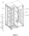
Figure 2 is a schematic stereoscopic structural diagram of the uninterrupted power supply from a left front view according to an embodiment of the present disclosure; -
Figure 3 is a schematic stereoscopic structural diagram of the uninterrupted power supply from a right rear view according to the present disclosure; -
Figure 4 is a schematic stereoscopic structural diagram of the uninterrupted power supply from a right front view according to the present disclosure; -
Figure 5 is a schematic stereoscopic structural diagram of an input end of a bypass module according to an embodiment of the present disclosure; -
Figure 6 is a schematic stereoscopic structural diagram of an output end of the bypass module according to an embodiment of the present disclosure. - The reference symbols include:
100 cabinet 110 output area 120 maintenance switch area 130 bypass input area 140 main input area 150 control wire inlet 160 upper wire inlet 170 lower wire inlet 180 wiring area 190 module area 200 monitoring module 300 bypass module 400 second power module 500 first power module m main copper bar assembly mA1 first horizontal main copper bar mB1 second horizontal main copper bar mC1 third horizontal main copper bar mA2 first vertical main copper bar mB2 second vertical main copper bar mC2 third vertical main copper bar b bypass copper bar assembly bA1 first bypass copper bar bB 1 second bypass copper bar bC1 third bypass copper bar bA2 fourth bypass copper bar bB2 fifth bypass copper bar bC2 sixth bypass copper bar o output copper bar assembly oA1 first output copper bar oB1 second horizontal output copper bar oC1 third horizontal output copper bar N1 horizontal neutral wire copper bar PE ground copper bar 520 battery wiring assembly 521 first anode wiring copper bar 522 first cathode wiring copper bar 523 second anode wiring copper bar 524 second cathode wiring copper bar - In order to clarify the technical problems to be solved, technical solutions and beneficial effects of the present disclosure, the present disclosure will be further described in detail below in conjunction with the accompanying drawings and embodiments. It should be understood that, the specific embodiments described herein are only used to illustrate the present disclosure, but not to limit the present disclosure.
- It should be noted that, when an element is referred to as being "fixed to" or "disposed at" another element, it may be either directly or indirectly on the another element. When an element is referred to as being "connected to" another element, it may be either directly or indirectly connected to the another element.
- It should be understood that, terms "length", "width", "up", "down", "front", "back", "left", "right", "vertical", "horizontal", "top", "bottom", "inside", "outside" and the like indicate orientation or position relationships based on those illustrated in the appended drawings, aim only to make it convenient to describe the present disclosure and simplify description, but do not indicate or imply that devices or elements as indicated must have specific orientations or be constructed and operated in specific orientations, and therefore cannot be construed as limitations to the present disclosure.
- In addition, terms "first" and "second" are used only to describe purposes, but cannot be construed as indicating or implying relative importance or implicitly indicating the number of technical features as indicated. Accordingly, a feature limited by "first" and "second" can explicitly or implicitly include one or more that feature. In the description of the present disclosure, "multiple" means two or more, unless otherwise defined specifically.
- Referring to
Figure 1 , which is a preferred embodiment of the present disclosure, the uninterrupted power supply comprises: acabinet 100 comprising awiring area 180 and amodule area 190 disposed in parallel along a width direction of thecabinet 100; anoutput area 110, amaintenance switch area 120, abypass input area 130, and amain input area 140 disposed in thewiring area 180 along a vertical direction; afirst power module 500, amonitoring module 200, abypass module 300 and asecond power module 400 disposed in themodule area 190 along a vertical direction. - The uninterrupted power supply of the present disclosure, while meeting high power density, maximally improves the reliability of a product through innovative layout, at the same time, it optimizes the overall layout, greatly reduces floor space and satisfies the market's requirements for arrangement costs of uninterrupted power supply equipment on the basis of existing corresponding power equipment; and can realize a multi-scenario configuration of an uninterrupted power supply, with flexible configuration, fast and convenient on-site deployment, and adaptation to on-site requirements of customers. The above-mentioned respective constituent parts will be further introduced below in detail, respectively.
- The
cabinet 100 is generally in the shape of a rectangular box, which is divided into awiring area 180 for convenient wiring and amodule area 190 installed with multiple modules. Thewiring area 180 and themodule area 190 are disposed in parallel along a width direction of thecabinet 100, that is, thewiring area 180 is disposed on one side inside thecabinet 100, and themodule area 190 is disposed on the other side inside thecabinet 100. Anupper wire inlet 160 and alower wire inlet 170 are disposed at the top and bottom of thecabinet 100 respectively, and theupper wire inlet 160 and thelower wire inlet 170 are disposed on the same side of thecabinet 100 as thewiring area 180, that is, theupper wire inlet 160 and thelower wire inlet 170 are disposed in thewiring area 180. - The
wiring area 180 may specifically comprise anoutput area 110, amaintenance switch area 120, abypass input area 130 and amain input area 140. Theoutput area 110, themaintenance switch area 120, thebypass input area 130 and themain input area 140 are sequentially stacked in thewiring area 180 of thecabinet 100 along a vertical direction from top to bottom. - The
module area 190 may specifically comprise acontrol wire inlet 150, afirst power module 500, amonitoring module 200, abypass module 300 and asecond power module 400. Thecontrol wire inlet 150 together with thefirst power module 500, themonitoring module 200, thebypass module 300 and thesecond power module 400 are sequentially stacked in themodule area 190 of thecabinet 100 along a vertical direction from top to bottom. There can be multiplefirst power modules 500 and multiplesecond power modules 400, wherein multiplefirst power modules 500 are stacked together along the vertical direction, and multiplesecond power modules 400 are also stacked together along the vertical direction. For example, in one embodiment of the present disclosure, there are fourfirst power modules 500 and foursecond power modules 400 respectively; in another embodiment of the present disclosure, there are sixfirst power modules 500 and foursecond power modules 400. - More specifically, the
first power module 500 is opposite to theoutput area 110 and themaintenance switch area 120 in a horizontal direction, and thebypass module 300 is opposite to thebypass input area 130 in the horizontal direction, and thesecond power module 400 is opposite to themain input area 140 in the horizontal direction. - As shown in
Figures 2 and3 , in one embodiment of the present disclosure, the uninterrupted power supply further comprises an output copper bar assembly o. The output copper bar assembly o comprises a first horizontal output copper bar oA1, a second horizontal output copper bar oB 1, a third horizontal output copper bar oC1, a first vertical output copper bar oA2, a second vertical output copper bar oB2 and a third vertical output copper bar oC2. The first horizontal output copper bar oA1, the second horizontal output copper bar oB 1 and the third horizontal output copper bar oC1 are fixedly connected together with the first vertical output copper bar oA2, the second vertical output copper bar oB2 and the third vertical output copper bar oC2 respectively. - Specifically, as shown in
Figure 2 , the first horizontal output copper bar oA1, the second horizontal output copper bar oB1 and the third horizontal output copper bar oC1 are disposed in theoutput area 110. Each of the first horizontal output copper bar oA1, the second horizontal output copper bar oB 1 and the third horizontal output copper bar oC1 extends along a depth direction of thecabinet 100, that is, the length direction of each of the first horizontal output copper bar oA1, the second horizontal output copper bar oB1 and the third horizontal output copper bar oC1 is same as the depth direction of thecabinet 100. The first horizontal output copper bar oA1, the second horizontal output copper bar oB1 and the third horizontal output copper bar oC1 are disposed in parallel to each other and are arranged along the width direction of thecabinet 100. - Specifically, as shown in
Figure 3 , the first vertical output copper bar oA2, the second vertical output copper bar oB2 and the third vertical output copper bar oC2 are disposed on a side wall of thecabinet 100 that is close to themodule area 190. The first vertical output copper bar oA2, the second vertical output copper bar oB2 and the third vertical output copper bar oC2 extend along a height direction of thecabinet 100, that is, the length direction of each of the first vertical output copper bar oA2, the second vertical output copper bar oB2 and the third vertical output copper bar oC2 is the same as the height direction of thecabinet 100. The first vertical output copper bar oA2, the second vertical output copper bar oB2 and the third vertical output copper bar oC2 are disposed in parallel to each other and are arranged along the depth direction of thecabinet 100. - As shown in
Figures 2 and4 , in another embodiment of the present disclosure, the uninterrupted power supply further comprises a horizontal neutral wire copper bar N1 and a vertical neutral wire copper bar N2. As shown inFigure 2 , the horizontal neutral wire copper bar N1 extends along the depth direction of thecabinet 100, and is arranged in parallel to the first horizontal output copper bar oA1, the second horizontal output copper bar oB1 and the third horizontal output copper bar oC1 along the width direction of thecabinet 100. As shown inFigure 4 , the vertical neutral wire copper bar N2 is disposed between thewiring area 180 and themodule area 190, and it extends along the height direction of thecabinet 100. - As shown in
Figure 2 , in other embodiments of the present disclosure, the uninterrupted power supply further comprises a ground copper bar PE. The ground copper bar PE is disposed above the first horizontal output copper bar oA1 and extends along the depth direction of thecabinet 100. - As shown in
Figures 2 and4 , the uninterrupted power supply further comprises a bypass copper bar assembly b. The bypass copper bar assembly b comprises a first bypass copper bar bA1, a second bypass copper bar bB1, a third bypass copper bar bC1, a fourth bypass copper bar bA2, a fifth bypass copper bar bB2 and a sixth bypass copper bar bC2. The fourth bypass copper bar bA2, the fifth bypass copper bar bB2 and the sixth bypass copper bar are fixedly connected together with the first bypass copper bar bA1, the second bypass copper bar bB1 and the third bypass copper bar bC1 respectively. - Specifically, the first bypass copper bar bA1, the second bypass copper bar bB1 and the third bypass copper bar bC1 are disposed in the
bypass input area 130. The first bypass copper bar bA1, the second bypass copper bar bB1 and the third bypass copper bar bC1 extend along the depth direction of thecabinet 100 and are arranged in parallel along the width direction of thecabinet 100. The fourth bypass copper bar bA2, the fifth bypass copper bar bB2 and the sixth bypass copper bar bC2 are disposed in themodule area 190. The fourth bypass copper bar bA2, the fifth bypass copper bar bB2 and the sixth bypass copper bar bC2 extend along the width direction of thecabinet 100 and are arranged in parallel along the height direction of thecabinet 100. - As shown in
Figure 5 , an input end of thebypass module 300 is fixedly connected together with the fourth bypass copper bar bA2, the fifth bypass copper bar bB2 and the sixth bypass copper bar bC2. As shown inFigure 6 , an output end of thebypass module 300 is fixedly connected together with the first vertical output copper bar oA2, the second vertical output copper bar oB2 and the third vertical output copper bar oC2. - As shown in
Figures 2 and4 , the uninterrupted power supply further comprises a main copper bar assembly m. The main copper bar assembly m comprises a first horizontal main copper bar mA1, a second horizontal main copper bar mB 1, a third horizontal main copper bar mC1, a first vertical main copper bar mA2, a second vertical main copper bar mB2 and a third vertical main copper bar mC2. - As shown in
Figure 2 , wherein, the first horizontal main copper bar mA1, the second horizontal main copper bar mB 1 and the third horizontal main copper bar mC1 are disposed in themain input area 140. The first horizontal main copper bar mA1, the second horizontal main copper bar mB 1 and the third horizontal main copper bar mC1 extend along the depth direction of thecabinet 100 and are arranged in parallel along the width direction of thecabinet 100. - As shown in
Figure 4 , the first vertical main copper bar mA2, the second vertical main copper bar mB2 and the third vertical main copper bar mC2 are disposed between thewiring area 180 and themodule area 190. The first vertical main copper bar mA2, the second vertical main copper bar mB2 and the third vertical main copper bar mC2 extend along the height direction of thecabinet 100 and are arranged in parallel along the depth direction of thecabinet 100. - As shown in
Figures 2 and4 , the uninterrupted power supply further comprises abattery wiring assembly 520. Thebattery wiring assembly 520 comprises a first anode wiring copper bar 521, a first cathode wiring copper bar 522, a second anodewiring copper bar 523 and a second cathodewiring copper bar 524. - As shown in
Figure 2 , the first anode wiring copper bar 521 and the first cathode wiring copper bar 522 are disposed above theoutput area 110. The first anode wiring copper bar 521 and the first cathode wiring copper bar 522 extend along the depth direction of thecabinet 100 and are arranged in parallel along the height direction of the cabinet. - As shown in
Figure 4 , the second anodewiring copper bar 523 and the second cathodewiring copper bar 524 are disposed between thewiring area 180 and themodule area 190. The second anodewiring copper bar 523 and the second cathodewiring copper bar 524 extend along the height direction of thecabinet 100 and are arranged in parallel along the depth direction of thecabinet 100. - The layout of various modules and copper bars of the switchless uninterrupted power supply is proper, convenient, and safe for wiring; the layout of the main copper bar assembly m, the output copper bar assembly o, the bypass copper bar assembly b, the neutral wire copper bar N, the ground copper bar PE and the
battery wiring assembly 520 improves the reliability of the system and the current sharing capacity of equipment. - The above only describes the preferred embodiments of the present disclosure. Those have ordinary skills in the art can make a variety of modifications in specific implementation and application scope based on the idea of the present disclosure. All modifications that do not depart from the concept of the present disclosure fall into the scope of protection of the present disclosure.
Claims (15)
- An uninterrupted power supply, characterized by comprising:a cabinet (100) comprising a wiring area (180) and a module area (190) disposed in parallel along a width direction of the cabinet (100);an output area (110), a maintenance switch area (120), a bypass input area (130) and a main input area (140) disposed in the wiring area (180) along a vertical direction;a first power module (500), a monitoring module (200), a bypass module (300), and a second power module (400) disposed in the module area (190) along the vertical direction.
- The uninterrupted power supply according to claim 1, characterized by further comprising a control wire inlet (150) disposed in the module area (190).
- The uninterrupted power supply according to claim 2, characterized in that, the control wire inlet (150), the first power module (500), the monitoring module (200), the bypass module (300) and the second power module (400) are sequentially stacked in the vertical direction.
- The uninterrupted power supply according to claim 1, characterized in that, the output area (110), the maintenance switch area (120), the bypass input area (130) and the main input area (140) are sequentially stacked in the vertical direction.
- The uninterrupted power supply according to claim 1, characterized in that, the output area (110) and the maintenance switch area (120) are opposite to the first power module (500) in a horizontal direction.
- The uninterrupted power supply according to any one of claims 1 to 5, characterized by further comprising an output copper bar assembly (o), which comprises a first horizontal output copper bar (oA1), a second horizontal output copper bar (oB1), a third horizontal output copper bar (oC1), a first vertical output copper bar (oA2), a second vertical output copper bar (oB2) and a third vertical output copper bar (oC2); the first horizontal output copper bar (oA1), the second horizontal output copper bar (oB1) and the third horizontal output copper bar (oC1) are disposed in the output area (110); the first vertical output copper bar (oA2), the second vertical output copper bar (oB2) and the third vertical output copper bar (oC2) are disposed on a side wall of the cabinet (100) that is close to the module area (190); the first horizontal output copper bar (oA1), the second horizontal output copper bar (oB1) and the third horizontal output copper bar (oC1) are fixedly connected together with the first vertical output copper bar (oA2), the second vertical output copper bar (oB2) and the third vertical output copper bar (oC2) respectively; and
the first horizontal output copper bar (oA1), the second horizontal output copper bar (oB1) and the third horizontal output copper bar (oC1) extend along a depth direction of the cabinet (100) and are arranged in parallel along the width direction of the cabinet (100); the first vertical output copper bar (oA2), the second vertical output copper bar (oB2) and the third vertical output copper bar (oC2) extend along a height direction of the cabinet (100) and are arranged in parallel along the depth direction of the cabinet (100). - The uninterrupted power supply according to claim 6, characterized by further comprising a horizontal neutral wire copper bar (N1) and a vertical neutral wire copper bar (N2), the horizontal neutral wire copper bar (N1) extends along the depth direction of the cabinet (100) and is arranged in parallel to the first horizontal output copper bar (oA1), the second horizontal output copper bar (oB1) and the third horizontal output copper bar (oC1) along the width direction of the cabinet (100); the vertical neutral wire copper bar (N2) extends along the height direction of the cabinet (100).
- The uninterrupted power supply according to claim 6 or 7, characterized by further comprising a ground copper bar (PE), which is disposed above the first horizontal output copper bar (oA1) and extends along the depth direction of the cabinet (100).
- The uninterrupted power supply according to claim 6, characterized in that, the bypass input area (130) is opposite to the bypass module (300) in a horizontal direction.
- The uninterrupted power supply according to claim 9, characterized by further comprising a bypass copper bar assembly (b), which comprises a first bypass copper bar (bA1), a second bypass copper bar (bB1), a third bypass copper bar (bC1), a fourth bypass copper bar (bA2), a fifth bypass copper bar (bB2) and a sixth bypass copper bar (bC2); the first bypass copper bar (bA1), the second bypass copper bar (bB1) and the third bypass copper bar (bC1) are disposed in the bypass input area (130); the fourth bypass copper bar (bA2), the fifth bypass copper bar (bB2) and the sixth bypass copper bar (bC2) are disposed in the module area (190); the first bypass copper bar (bA1), the second bypass copper bar (bB1) and the third bypass copper bar (bC1) are fixedly connected together with the fourth bypass copper bar (bA2), the fifth bypass copper bar (bB2) and the sixth bypass copper bar (bC2) respectively;the first bypass copper bar (bA1), the second bypass copper bar (bB1) and the third bypass copper bar (bC1) extend along the depth direction of the cabinet (100) and are arranged in parallel along the width direction of the cabinet (100); the fourth bypass copper bar (bA2), the fifth bypass copper bar (bB2) and the sixth bypass copper bar (bC2) extend along the width direction of the cabinet (100) and are arranged in parallel along the height direction of the cabinet (100); andan input end of the bypass module (300) is fixedly connected together with the fourth bypass copper bar (bA2), the fifth bypass copper bar (bB2), and the sixth bypass copper bar (bC2), and an output end of the bypass module (300) is fixedly connected together with the first vertical output copper bar (oA2), the second vertical output copper bar (oB2), and the third vertical output copper bar (oC2).
- The uninterrupted power supply according to any one of claims 1 to 5, characterized in that the main input area (140) is opposite to the second power module (400) in a horizontal direction.
- The uninterrupted power supply according to claim 11, characterized by further comprising a main copper bar assembly (m), which comprises a first horizontal main copper bar (mA1), a second horizontal main copper bar (mB1), a third horizontal main copper bar (mC1), a first vertical main copper bar (mA2), a second vertical main copper bar (mB2) and a third vertical main copper bar (mC2); the first horizontal main copper bar (mA1), the second horizontal main copper bar (mB1) and the third horizontal main copper bar (mC1) are disposed in the main input area (140); the first vertical main copper bar (mA2), the second vertical main copper bar (mB2) and the third vertical main copper bar (mC2) are disposed between the wiring area (180) and the module area (190); and the first horizontal main copper bar (mA1), the second horizontal main copper bar (mB1) and the third horizontal main copper bar (mC1) extend along the depth direction of the cabinet (100) and are arranged in parallel along the width direction of the cabinet (100); the first vertical main copper bar (mA2), the second vertical main copper bar (mB2) and the third vertical main copper bar (mC2) extend along the height direction of the cabinet (100) and are arranged in parallel along the depth direction of the cabinet (100).
- The uninterrupted power supply according to any one of claims 1 to 5, characterized by further comprising a battery wiring assembly (520), the battery wiring assembly (520) comprises a first anode wiring copper bar (521), a first cathode wiring copper bar (522), a second anode wiring copper bar (523) and a second cathode wiring copper bar (524); the first anode wiring copper bar (521) and the first cathode wiring copper bar (522) are disposed above the output area (110); the second anode wiring copper bar (523) and the second cathode wiring copper bar (524) are disposed between the wiring area (180) and the module area (190).
- The uninterrupted power supply according to claim 13, characterized in that, the first anode wiring copper bar (521) and the first cathode wiring copper bar (522) extend along the depth direction of the cabinet (100) and are arranged in parallel along the height direction of the cabinet (100); the second anode wiring copper bar (523) and the second cathode wiring copper bar (524) extend along the height direction of the cabinet (100) and are arranged in parallel along the depth direction of the cabinet (100).
- The uninterrupted power supply according to claim 1, characterized in that, an upper wire inlet (160) and a lower wire inlet (170) are disposed at a top and a bottom of the cabinet (100) respectively, and the upper wire inlet (160) and the lower wire inlet (170) are disposed on the same side of the cabinet (100) as the output area (110), the maintenance switch area (120), the bypass input area (130) and the main input area (140).
Applications Claiming Priority (1)
| Application Number | Priority Date | Filing Date | Title |
|---|---|---|---|
| CN202322669227.2U CN221126942U (en) | 2023-09-28 | 2023-09-28 | Uninterruptible power supply |
Publications (1)
| Publication Number | Publication Date |
|---|---|
| EP4531507A1 true EP4531507A1 (en) | 2025-04-02 |
Family
ID=91334930
Family Applications (1)
| Application Number | Title | Priority Date | Filing Date |
|---|---|---|---|
| EP24178952.8A Pending EP4531507A1 (en) | 2023-09-28 | 2024-05-29 | Uninterrupted power supply |
Country Status (2)
| Country | Link |
|---|---|
| EP (1) | EP4531507A1 (en) |
| CN (1) | CN221126942U (en) |
Citations (2)
| Publication number | Priority date | Publication date | Assignee | Title |
|---|---|---|---|---|
| US11469679B2 (en) * | 2017-11-14 | 2022-10-11 | Fuji Electric Co., Ltd. | Power converter device with non-overlapping bus bars |
| CN218632926U (en) * | 2022-11-08 | 2023-03-14 | 维谛公司 | Uninterrupted power source cabinet |
-
2023
- 2023-09-28 CN CN202322669227.2U patent/CN221126942U/en active Active
-
2024
- 2024-05-29 EP EP24178952.8A patent/EP4531507A1/en active Pending
Patent Citations (2)
| Publication number | Priority date | Publication date | Assignee | Title |
|---|---|---|---|---|
| US11469679B2 (en) * | 2017-11-14 | 2022-10-11 | Fuji Electric Co., Ltd. | Power converter device with non-overlapping bus bars |
| CN218632926U (en) * | 2022-11-08 | 2023-03-14 | 维谛公司 | Uninterrupted power source cabinet |
Also Published As
| Publication number | Publication date |
|---|---|
| CN221126942U (en) | 2024-06-11 |
Similar Documents
| Publication | Publication Date | Title |
|---|---|---|
| US9670689B2 (en) | Container based data center solutions | |
| EP0575060B1 (en) | Modular battery cabinet assembly | |
| US20120049706A1 (en) | Air Flow Management Enclosure | |
| CN101087059A (en) | Modular UPS systems and methods using modular interconnect assemblies | |
| US20120201002A1 (en) | System and method for an optimizable rack solution | |
| EP3621420B1 (en) | Photovoltaic inverter | |
| US20110286176A1 (en) | Module for a telecommunications subrack and a telecommunications subrack | |
| WO2014172602A1 (en) | Electronic device and battery enclosure | |
| US20100138586A1 (en) | Adaptive and modular ups system and method | |
| CN221126942U (en) | Uninterruptible power supply | |
| US11322791B2 (en) | Multi-battery assembly and container comprising such an assembly | |
| US7159062B2 (en) | Electronic shelf unit with management function performed by a common shelf card with the assistance of an auxiliary interface board | |
| CN220873763U (en) | Modularized battery rack with adjusting function | |
| EP4525266A1 (en) | Switchless uninterrupted power supply | |
| CN213027840U (en) | I-type three-level structure direct parallel power module of energy storage converter | |
| CN215420942U (en) | Signal distribution terminal and signal acquisition system | |
| US20210320318A1 (en) | Modular and compact implantation of battery modules in a container | |
| CN118283977A (en) | Electronic devices and power systems | |
| CN218472543U (en) | AC/DC power distribution row cabinet | |
| US20250089196A1 (en) | Power equipment | |
| CN221806211U (en) | A dual power supply cabinet | |
| CN222996052U (en) | Power distribution cabinet for complete power distribution equipment and complete power distribution equipment having the same | |
| US20250176125A1 (en) | Prefabricated Alternating-Current Integrated Power Module | |
| CN216720631U (en) | DVR rack and voltage equipment | |
| CN222757062U (en) | A low voltage switch cabinet carrying device |
Legal Events
| Date | Code | Title | Description |
|---|---|---|---|
| PUAI | Public reference made under article 153(3) epc to a published international application that has entered the european phase |
Free format text: ORIGINAL CODE: 0009012 |
|
| STAA | Information on the status of an ep patent application or granted ep patent |
Free format text: STATUS: REQUEST FOR EXAMINATION WAS MADE |
|
| 17P | Request for examination filed |
Effective date: 20240529 |
|
| AK | Designated contracting states |
Kind code of ref document: A1 Designated state(s): AL AT BE BG CH CY CZ DE DK EE ES FI FR GB GR HR HU IE IS IT LI LT LU LV MC ME MK MT NL NO PL PT RO RS SE SI SK SM TR |