EP4531396A1 - Image encoding device, image decoding device, image encoding method, and image decoding method - Google Patents
Image encoding device, image decoding device, image encoding method, and image decoding method Download PDFInfo
- Publication number
- EP4531396A1 EP4531396A1 EP23839335.9A EP23839335A EP4531396A1 EP 4531396 A1 EP4531396 A1 EP 4531396A1 EP 23839335 A EP23839335 A EP 23839335A EP 4531396 A1 EP4531396 A1 EP 4531396A1
- Authority
- EP
- European Patent Office
- Prior art keywords
- image
- bitstream
- particular region
- picture
- information
- Prior art date
- Legal status (The legal status is an assumption and is not a legal conclusion. Google has not performed a legal analysis and makes no representation as to the accuracy of the status listed.)
- Pending
Links
Images







Classifications
-
- H—ELECTRICITY
- H04—ELECTRIC COMMUNICATION TECHNIQUE
- H04N—PICTORIAL COMMUNICATION, e.g. TELEVISION
- H04N19/00—Methods or arrangements for coding, decoding, compressing or decompressing digital video signals
- H04N19/46—Embedding additional information in the video signal during the compression process
- H04N19/463—Embedding additional information in the video signal during the compression process by compressing encoding parameters before transmission
-
- H—ELECTRICITY
- H04—ELECTRIC COMMUNICATION TECHNIQUE
- H04N—PICTORIAL COMMUNICATION, e.g. TELEVISION
- H04N19/00—Methods or arrangements for coding, decoding, compressing or decompressing digital video signals
- H04N19/20—Methods or arrangements for coding, decoding, compressing or decompressing digital video signals using video object coding
-
- H—ELECTRICITY
- H04—ELECTRIC COMMUNICATION TECHNIQUE
- H04N—PICTORIAL COMMUNICATION, e.g. TELEVISION
- H04N19/00—Methods or arrangements for coding, decoding, compressing or decompressing digital video signals
- H04N19/30—Methods or arrangements for coding, decoding, compressing or decompressing digital video signals using hierarchical techniques, e.g. scalability
-
- H—ELECTRICITY
- H04—ELECTRIC COMMUNICATION TECHNIQUE
- H04N—PICTORIAL COMMUNICATION, e.g. TELEVISION
- H04N19/00—Methods or arrangements for coding, decoding, compressing or decompressing digital video signals
- H04N19/30—Methods or arrangements for coding, decoding, compressing or decompressing digital video signals using hierarchical techniques, e.g. scalability
- H04N19/39—Methods or arrangements for coding, decoding, compressing or decompressing digital video signals using hierarchical techniques, e.g. scalability involving multiple description coding [MDC], i.e. with separate layers being structured as independently decodable descriptions of input picture data
-
- H—ELECTRICITY
- H04—ELECTRIC COMMUNICATION TECHNIQUE
- H04N—PICTORIAL COMMUNICATION, e.g. TELEVISION
- H04N19/00—Methods or arrangements for coding, decoding, compressing or decompressing digital video signals
- H04N19/46—Embedding additional information in the video signal during the compression process
-
- H—ELECTRICITY
- H04—ELECTRIC COMMUNICATION TECHNIQUE
- H04N—PICTORIAL COMMUNICATION, e.g. TELEVISION
- H04N19/00—Methods or arrangements for coding, decoding, compressing or decompressing digital video signals
- H04N19/70—Methods or arrangements for coding, decoding, compressing or decompressing digital video signals characterised by syntax aspects related to video coding, e.g. related to compression standards
-
- H—ELECTRICITY
- H04—ELECTRIC COMMUNICATION TECHNIQUE
- H04N—PICTORIAL COMMUNICATION, e.g. TELEVISION
- H04N19/00—Methods or arrangements for coding, decoding, compressing or decompressing digital video signals
- H04N19/85—Methods or arrangements for coding, decoding, compressing or decompressing digital video signals using pre-processing or post-processing specially adapted for video compression
-
- H—ELECTRICITY
- H04—ELECTRIC COMMUNICATION TECHNIQUE
- H04N—PICTORIAL COMMUNICATION, e.g. TELEVISION
- H04N21/00—Selective content distribution, e.g. interactive television or video on demand [VOD]
- H04N21/20—Servers specifically adapted for the distribution of content, e.g. VOD servers; Operations thereof
- H04N21/23—Processing of content or additional data; Elementary server operations; Server middleware
- H04N21/234—Processing of video elementary streams, e.g. splicing of video streams or manipulating encoded video stream scene graphs
- H04N21/2343—Processing of video elementary streams, e.g. splicing of video streams or manipulating encoded video stream scene graphs involving reformatting operations of video signals for distribution or compliance with end-user requests or end-user device requirements
- H04N21/234345—Processing of video elementary streams, e.g. splicing of video streams or manipulating encoded video stream scene graphs involving reformatting operations of video signals for distribution or compliance with end-user requests or end-user device requirements the reformatting operation being performed only on part of the stream, e.g. a region of the image or a time segment
-
- H—ELECTRICITY
- H04—ELECTRIC COMMUNICATION TECHNIQUE
- H04N—PICTORIAL COMMUNICATION, e.g. TELEVISION
- H04N21/00—Selective content distribution, e.g. interactive television or video on demand [VOD]
- H04N21/40—Client devices specifically adapted for the reception of or interaction with content, e.g. set-top-box [STB]; Operations thereof
- H04N21/43—Processing of content or additional data, e.g. demultiplexing additional data from a digital video stream; Elementary client operations, e.g. monitoring of home network or synchronising decoder's clock; Client middleware
- H04N21/431—Generation of visual interfaces for content selection or interaction; Content or additional data rendering
- H04N21/4318—Generation of visual interfaces for content selection or interaction; Content or additional data rendering by altering the content in the rendering process, e.g. blanking, blurring or masking an image region
-
- H—ELECTRICITY
- H04—ELECTRIC COMMUNICATION TECHNIQUE
- H04N—PICTORIAL COMMUNICATION, e.g. TELEVISION
- H04N21/00—Selective content distribution, e.g. interactive television or video on demand [VOD]
- H04N21/40—Client devices specifically adapted for the reception of or interaction with content, e.g. set-top-box [STB]; Operations thereof
- H04N21/43—Processing of content or additional data, e.g. demultiplexing additional data from a digital video stream; Elementary client operations, e.g. monitoring of home network or synchronising decoder's clock; Client middleware
- H04N21/44—Processing of video elementary streams, e.g. splicing a video clip retrieved from local storage with an incoming video stream or rendering scenes according to encoded video stream scene graphs
- H04N21/44008—Processing of video elementary streams, e.g. splicing a video clip retrieved from local storage with an incoming video stream or rendering scenes according to encoded video stream scene graphs involving operations for analysing video streams, e.g. detecting features or characteristics in the video stream
-
- H—ELECTRICITY
- H04—ELECTRIC COMMUNICATION TECHNIQUE
- H04N—PICTORIAL COMMUNICATION, e.g. TELEVISION
- H04N21/00—Selective content distribution, e.g. interactive television or video on demand [VOD]
- H04N21/40—Client devices specifically adapted for the reception of or interaction with content, e.g. set-top-box [STB]; Operations thereof
- H04N21/43—Processing of content or additional data, e.g. demultiplexing additional data from a digital video stream; Elementary client operations, e.g. monitoring of home network or synchronising decoder's clock; Client middleware
- H04N21/44—Processing of video elementary streams, e.g. splicing a video clip retrieved from local storage with an incoming video stream or rendering scenes according to encoded video stream scene graphs
- H04N21/4402—Processing of video elementary streams, e.g. splicing a video clip retrieved from local storage with an incoming video stream or rendering scenes according to encoded video stream scene graphs involving reformatting operations of video signals for household redistribution, storage or real-time display
- H04N21/440245—Processing of video elementary streams, e.g. splicing a video clip retrieved from local storage with an incoming video stream or rendering scenes according to encoded video stream scene graphs involving reformatting operations of video signals for household redistribution, storage or real-time display the reformatting operation being performed only on part of the stream, e.g. a region of the image or a time segment
-
- H—ELECTRICITY
- H04—ELECTRIC COMMUNICATION TECHNIQUE
- H04N—PICTORIAL COMMUNICATION, e.g. TELEVISION
- H04N21/00—Selective content distribution, e.g. interactive television or video on demand [VOD]
- H04N21/40—Client devices specifically adapted for the reception of or interaction with content, e.g. set-top-box [STB]; Operations thereof
- H04N21/45—Management operations performed by the client for facilitating the reception of or the interaction with the content or administrating data related to the end-user or to the client device itself, e.g. learning user preferences for recommending movies, resolving scheduling conflicts
- H04N21/454—Content or additional data filtering, e.g. blocking advertisements
- H04N21/4542—Blocking scenes or portions of the received content, e.g. censoring scenes
-
- H—ELECTRICITY
- H04—ELECTRIC COMMUNICATION TECHNIQUE
- H04N—PICTORIAL COMMUNICATION, e.g. TELEVISION
- H04N21/00—Selective content distribution, e.g. interactive television or video on demand [VOD]
- H04N21/40—Client devices specifically adapted for the reception of or interaction with content, e.g. set-top-box [STB]; Operations thereof
- H04N21/45—Management operations performed by the client for facilitating the reception of or the interaction with the content or administrating data related to the end-user or to the client device itself, e.g. learning user preferences for recommending movies, resolving scheduling conflicts
- H04N21/462—Content or additional data management e.g. creating a master electronic programme guide from data received from the Internet and a Head-end or controlling the complexity of a video stream by scaling the resolution or bit-rate based on the client capabilities
- H04N21/4627—Rights management associated to the content
Definitions
- Patent Literature 1 discloses a video encoding method and a decoding method using an adaptive coupled prefilter and postfilter.
- Patent Literature 2 discloses a method of encoding image data for loading into an artificial intelligence (AI) integrated circuit.
- AI artificial intelligence
- An object of the present disclosure is to enable both protection of personal privacy information and execution of a machine task or provision of human vision using such privacy information on an image decoder when an image is transmitted from an image encoder to the image decoder.
- An image decoder includes: circuitry; and a memory connected to the circuitry, in which, in operation, the circuitry decodes a first bitstream to acquire a first image, decodes a second bitstream to acquire specification information specifying a particular region in the first image and a second image containing image data for the particular region, and generates a third image based on the first image, the specification information, and the second image.
- a conventional encoding method has aimed to provide optimal video under bit rate constraints for human vision.
- VCM video coding for machines
- machines can communicate with each other and execute tasks without human intervention, while in other cases, additional processing by humans may be necessary for decompressed specific streams.
- Such cases include a case where for example, in surveillance cameras, a human "supervisor" searches for a specific person or scene in a video.
- bitstreams are used by both humans and machines.
- features can be used for image correction functions for humans and used for object detection and segmentation for machines.
- Typical system architecture includes a pair of image encoder and image decoder.
- the input of the system is a video, a still image, or a feature quantity.
- Examples of a machine task include object detection, object segmentation, object tracking, action recognition, pose estimation, or a discretionary combination thereof. There is a possibility that human vision is one of the use cases that can be used along with the machine task.
- a captured image contains privacy information such as an individual's face and a vehicle tag
- the image containing privacy information is transmitted from the image encoder to the image decoder even when the machine task does not require such information. This may result in a leakage of the privacy information.
- transmission of an image in which masking such as blurring processing is applied to privacy information from the image encoder to the image decoder can be considered, there is a problem that privacy information cannot be used when such information is needed for a machine task or human vision.
- the present inventors have conceived the present disclosure based on the finding that the above problem can be solved by transmitting a bitstream of an image containing privacy information and a bitstream of an image not containing privacy information individually from an image encoder to an image decoder and combining these images on the image decoder when privacy information is necessary.
- the image decoder is designed to protect personal privacy information by not allowing privacy information to be included in the first bitstream.
- an image processing system is designed to execute a machine task or provide human vision using privacy information on the image decoder.
- the particular region in the first image preferably includes an image in which masking is applied to a privacy region including privacy information.
- privacy information included in the particular region in the first image can be appropriately protected by masking.
- the second image and the third image each preferably contain an image in which the masking is not applied to the privacy region included in the particular region.
- the second image and the third image each contain an image in which the masking is not applied to the privacy region included in the particular region. This makes it possible to appropriately execute a machine task or provide human vision using privacy information on the image decoder.
- the particular region in the first image includes an image in which masking is applied to a privacy region including privacy information
- the second image contains an image in which the masking is not applied to the privacy region included in the particular region
- the circuitry in generation of the third image, generates the third image using the first image for an application of an image with masked privacy information, and generates the third image using the first image and the second image for an application of an image with unmasked privacy information.
- the image processing system is designed to switch between a machine task or human vision using an image with masked privacy information and a machine task or human vision using an image with unmasked privacy information on the image decoder and execute any of these.
- the specification information preferably includes information indicating a position and a size of the particular region in the first image.
- the position and the size of the particular region in the first image can be appropriately specified by the specification information.
- the specification information preferably further includes information indicating a correspondence relationship between the particular region in the first image and the second image.
- the correspondence relationship between the particular region in the first image and the second image can be appropriately specified by the specification information.
- the circuitry preferably decodes a header area of the second bitstream to acquire the specification information.
- the specification information is stored in the header area of the second bitstream. This makes it possible to readily decode the specification information from the second bitstream.
- the image decoder in the image decoder according to any one of the first to seventh aspects, it is preferred that, out of the specification information, information indicating a position and a size of the particular region in the first image be stored in a header area of the first bitstream, and that the circuitry decode the header area of the first bitstream to acquire the information.
- information that is basically included in the header area of the first bitstream can be used as specification information.
- the image data contained in the second image is preferably image data about a difference between the particular region inside the first image and the particular region inside the third image.
- a coding amount transmitted from an image encoder to the image decoder can be reduced compared with a case where image data for the particular region that is unmasked is transmitted.
- the image data contained in the second image is preferably image data for the particular region in the third image.
- the circuitry just needs to replace image data for the particular region in the first image with the image data in the second image. This helps to reduce a processing load on the circuitry.
- the particular region include a plurality of particular regions, and that a picture of the second bitstream include the image data for one of the plurality of particular regions.
- the picture of the second bitstream only includes the image data for the one particular region. This makes it easier to associate each of the particular regions inside the first image with the second image.
- the particular region include a plurality of particular regions, and that a picture of the second bitstream include the image data for the plurality of particular regions.
- the picture of the second bitstream includes the image data for the plurality of particular regions. This helps to reduce a number of pictures of the second bitstream to be transmitted from an image encoder to the image decoder.
- the particular region is preferably included in one or more coding unit blocks that compose a picture of the second bitstream.
- the particular region is included in one or more coding unit blocks. This enables the circuitry to appropriately decode the particular region.
- the particular region is preferably included in either a subpicture or a tile that composes a picture of the second bitstream.
- the particular region is included in a subpicture or a tile. This enables the circuitry to appropriately decode the particular region.
- the particular region include a plurality of particular regions, and that the second image contain the image data associated with the plurality of particular regions.
- one piece of the second image can contain the plurality of particular regions corresponding to the plurality of target objects.
- a picture size of the first bitstream and a picture size of the second bitstream are preferably equal to each other.
- the picture size of the first bitstream and the picture size of the second bitstream are equal to each other. This makes it easier to associate the particular region inside the first image with the second image.
- a picture of the second bitstream is preferably an intra-coded picture for which intra frame prediction is performed.
- the picture of the second bitstream is an intra-coded picture, factors such as movement of a target object over time are not required to be taken into consideration. This eliminates the need for storing a previous frame and calculating a difference from the previous frame, for example.
- the first bitstream and the second bitstream can be readily transmitted by the base layer and the enhancement layer in the multilayer form standardized by VVC or other standards.
- the specification information is stored in the header area of the second bitstream. This enables an image decoder to readily decode the specification information from the second bitstream.
- the circuitry preferably stores information out of the specification information in a header area of the first bitstream, the information indicating a position and a size of the particular region in the first image.
- the picture of the second bitstream only includes the image data for the one particular region. This makes it easier to associate each of the particular regions inside the first image with the second image.
- the particular region include a plurality of particular regions, and that a picture of the second bitstream include the image data for the plurality of particular regions.
- the picture of the second bitstream includes the image data for the plurality of particular regions. This helps to reduce a number of pictures of the second bitstream to be transmitted from the image encoder to an image decoder.
- the particular region is included in one or more coding unit blocks. This enables an image decoder to appropriately decode the particular region.
- the particular region is preferably included in either a subpicture or a tile that composes a picture of the second bitstream.
- the particular region is included in a subpicture or a tile. This enables an image decoder to appropriately decode the particular region.
- the particular region include a plurality of particular regions, and that the second image contain the image data associated with the plurality of particular regions.
- the picture size of the first bitstream and the picture size of the second bitstream are equal to each other. This makes it easier to associate the particular region inside the first image with the second image.
- a picture of the second bitstream is preferably an intra-coded picture for which intra frame prediction is performed.
- a picture of the second bitstream is preferably an inter frame picture for which inter frame prediction is performed using a reference picture that is acquired by decoding either the second bitstream or the first bitstream.
- the circuitry preferably transmits the first bitstream to an image decoder by a base layer in a multilayer form and transmits the second bitstream to the image decoder by an enhancement layer in the multilayer form.
- the first bitstream and the second bitstream can be readily transmitted by the base layer and the enhancement layer in the multilayer form standardized by VVC or other standards.
- the circuitry preferably transmits the first bitstream and the second bitstream to an image decoder by different transmission lines.
- the first bitstream is transmitted by the transmission line such as a public network
- the second bitstream is transmitted by the transmission line such as a private network. This enables both reduction of transmission costs and protection of privacy information.
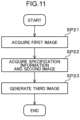
- An image decoding method includes: decoding a first bitstream to acquire a first image; decoding a second bitstream to acquire specification information specifying a particular region in the first image and a second image containing image data for the particular region; and generating a third image based on the first image, the specification information, and the second image.
- the image decoding method is designed to protect personal privacy information by not allowing privacy information to be included in the first bitstream.
- an image processing system is designed to execute a machine task or provide human vision using privacy information on the image decoder.
- An image encoding method includes: specifying a particular region in an input image, generating specification information about the particular region; generating a first image in which the particular region is processed in the input image; generating a second image that contains image data associated with the particular region; encoding the first image to generate and output a first bitstream; and encoding the specification information and the second image to generate and output a second bitstream.
- the image encoding method is designed to protect personal privacy information by not allowing privacy information to be included in the first bitstream.
- the image processing system is designed to execute a machine task or provide human vision using privacy information on the image decoder.
- FIG. 1 is a diagram illustrating a simplified configuration of an image processing system according to an embodiment of the present disclosure.
- the image processing system includes an image encoder 1, transmission lines NW1, NW2, and an image decoder 2.
- the image encoder 1 includes a region specification unit 11, a first image generator 12, a second image generator 13, a first encoder 14, and a second encoder 15.
- the region specification unit 11 specifies a particular region in an input image D1 and generates specification information D2 about the particular region.
- the first image generator 12 generates a first image D3 in which the particular region is processed in the input image D1.
- the second image generator 13 generates a second image D4 that contains image data associated with the particular region.
- the first encoder 14 encodes the first image D3 to generate and output a first bitstream D5.
- the first bitstream D5 is transmitted to the image decoder 2 via the transmission line NW1.
- the second encoder 15 encodes the specification information D2 and the second image D4 to generate and output a second bitstream D6.
- the second bitstream D6 is transmitted to the image decoder 2 via the transmission line NW2 different from the transmission line NW1.
- the transmission lines NW1, NW2 are each the Internet, a wide area network (WAN), a local area network (LAN), or a combination of any of these.
- the transmission lines NW1, NW2 are each not necessarily limited to a bidirectional communication network, but may be a unidirectional communication network through which broadcast waves are transmitted by broadcasting such as terrestrial digital broadcasting or satellite broadcasting.
- the transmission lines NW1, NW2 may each be a recording medium such as a digital versatile disc (DVD) or a Blu-ray disc (BD) on which the first bitstream D5 or the second bitstream D6 is recorded.
- the transmission line NW1 is a public network, for example, whereas the transmission line NW2 is a private network or the like for secured communication with limited access. If different limitations can be placed on access to the first bitstream D5 and the second bitstream D6, the transmission lines NW1, NW2 may be physically identical communication networks or recording media.
- the image decoder 2 includes a first decoder 21, a second decoder 22, and an image generator 23.
- the first decoder 21 receives the first bitstream D5 transmitted from the first encoder 14 via the transmission line NW1.
- the first decoder 21 decodes the received first bitstream D5 to acquire a first image D7 equivalent to the first image D3.
- the second decoder 22 receives the second bitstream D6 transmitted from the second encoder 15 via the transmission line NW2.
- the second decoder 22 decodes the received second bitstream D6 to acquire specification information D8 equivalent to the specification information D2 and a second image D9 equivalent to the second image D4.
- the image generator 23 generates a third image D10 equivalent to the input image D1, based on the first image D7, the specification information D8, and the second image D9. Specifically, in a use case in which an image not containing privacy information is used (i.e., an application of an image with masked privacy information), the image generator 23 generates the third image D10 using the first image D7 as it is, for example.
- the use case in which an image not containing privacy information is used is a case in which the image is viewed by a user who does not have a special right to access such information or the image is used for a machine task that does not require detailed information such as a face or a vehicle tag, for example.
- the image generator 23 In a use case in which an image containing privacy information is used (i.e., an application of an image with unmasked privacy information), the image generator 23, based on the specification information D8, generates a third image D10 using the first image D7 and the second image D9 for image data in the particular region and generates a third image D10 using the first image D7 for image data outside the particular region, for example.
- the use case in which an image containing privacy information is used is a case in which the image is viewed by a user who has a special right to access such information or the image is used for a machine task that also requires detailed information such as a face or a vehicle tag, for example.
- the image processing system is designed to switch between a machine task or human vision using an image with masked privacy information and a machine task or human vision using an image with unmasked privacy information on the image decoder 2 and execute any of these.
- the machine task is, for example, object detection, object segmentation, object tracking, action recognition, or pose estimation.
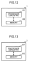
- FIG. 12 is a diagram illustrating a simplified implementation example of the image encoder 1.
- the image encoder 1 has a configuration that includes a processor 101 and a memory 102 connected to the processor 101. However, the memory 102 may be included in the processor 101.
- the processor 101 is circuitry that executes information processing.
- the processor 101 includes a central processing unit (CPU) or a graphics processing unit (GPU).
- the memory 102 includes a semiconductor memory such as a read only memory (ROM) or a random access memory (RAM), a magnetic disk, or an optical disk.
- the memory 102 stores information necessary for the processor 101 to execute encoding processing and the like. For example, the memory 102 stores the input image D1, the specification information D2, the first image D3, and the second image D4.
- the memory 102 stores a program.
- the processor 101 executes the program read from the memory 102, the processor 101 functions as the region specification unit 11, the first image generator 12, the second image generator 13, the first encoder 14, and the second encoder 15.
- FIG. 13 is a diagram illustrating a simplified implementation example of the image decoder 2.
- the image decoder 2 has a configuration that includes a processor 201 and a memory 202 connected to the processor 201. However, the memory 202 may be included in the processor 201.
- the processor 201 is circuitry that executes information processing.
- the processor 201 includes a CPU or a GPU.
- the memory 202 includes a semiconductor memory such as a ROM or a RAM, a magnetic disk, or an optical disk.
- the memory 202 stores information necessary for the processor 201 to execute decoding processing and the like. For example, the memory 202 stores the first bitstream D5, the second bitstream D6, the first image D7, the specification information D8, and the second image D9.
- the memory 202 stores a program. When the processor 201 executes the program read from the memory 202, the processor 201 functions as the first decoder 21, the second decoder 22, and the image generator 23.
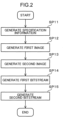
- FIG. 2 is a flowchart illustrating a flow of processing executed by the image encoder 1.
- the region specification unit 11 specifies a particular region in the input image D1 and generates the specification information D2 about the particular region.
- step SP12 the first image generator 12 generates the first image D3 in which the particular region is processed in the input image D1.
- step SP13 the second image generator 13 generates the second image D4 that contains image data associated with the particular region.
- step SP14 the first encoder 14 encodes the first image D3 to generate and output the first bitstream D5.
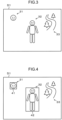
- FIG. 3 is a diagram illustrating an example of the input image D1.
- the input image D1 contains an image 31 of a human face, an image 32 of a whole body including a human face, and an image 33 of a background.
- the human face is an example of personal privacy information.
- the privacy information is, for example, a vehicle tag and a nameplate of a house.
- FIG. 4 is a diagram illustrating bounding boxes 41, 42 as an example of the particular region.
- the region specification unit 11 sets the bounding box 41, which surrounds a privacy region including the image 31 by a rectangle, as one of the particular regions.
- the region specification unit 11 also sets the bounding box 42, which surrounds a privacy region including the image 32 by a rectangle, as one of the particular regions. Since the image 33 does not contain privacy information, a bounding box is not set for the image.
- the specification information D2 includes information indicating positions and sizes of the bounding boxes 41, 42 in the first image D3.
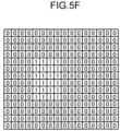
- FIGS. 5A to 5F are diagrams each illustrating an example of the specification information D2.
- the specification information D2 includes position coordinates (X1, Y1) of a particular vertex of a bounding box, a vertical size H of the bounding box, and a horizontal size W of the bounding box.
- the specification information D2 includes position coordinates (X1, Y1) of a particular vertex of a bounding box and position coordinates (X4, Y4) of a vertex diagonally opposed to the particular vertex.
- FIG. 5A the specification information D2 includes position coordinates (X1, Y1) of a particular vertex of a bounding box, a vertical size H of the bounding box, and a horizontal size W of the bounding box.
- the specification information D2 includes position coordinates (X1, Y1) of a particular vertex of a bounding box and position coordinates (X4, Y4) of a vertex diagonally opposed to the particular vertex.
- the specification information D2 includes position coordinates (X0, Y0) of a center of a bounding box, a vertical size H of the bounding box, and a horizontal size W of the bounding box.
- the specification information D2 includes position coordinates (X1, Y1), (X2, Y2), (X3, Y3), (X4, Y4) of four vertices of a bounding box.
- FIG. 5E a position and a size of even a slanting bounding box can be specified.
- the specification information D2 includes mask information to denote pixel positions inside the particular region by "1" and pixel positions outside the particular region by "0".
- the specification information D2 includes information indicating a correspondence relationship between the bounding boxes 41, 42 in the first image D3 and the second image D4. If the second image D4 contains a plurality of bounding boxes 41, 42, the specification information D2 includes information indicating a correspondence relationship between the bounding boxes 41, 42 in the first image D3 and the bounding boxes 41, 42 in the second image D4.
- FIG. 6 is a diagram illustrating an example of the first image D3.
- a region inside each of the bounding boxes 41, 42 contained in the first image D3 includes an image in which masking is applied to a privacy region including privacy information.
- FIG. 6 illustrates an example in which silhouette processing is applied to the privacy regions.
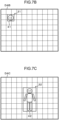
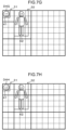
- FIGS. 7A to 7H are diagrams each illustrating an example of the second image D4.
- a second image D4A has a picture size equal to that of the input image D1.
- the coding unit block is a coding unit (CU), a coding tree unit (CTU), or the like and has a size of 8 pixels by 8 pixels, for example.
- image data for a region outside bounding boxes 41, 42 may be identical to that of the input image D1, or may be padded with meaningless data (for example, "0").
- the positions and sizes of the bounding boxes 41, 42 in the second image D4A are equal to the positions and sizes of the bounding boxes 41, 42 in the input image D1.
- a region inside each of the bounding boxes 41, 42 contained in the first image D7 at the image decoder 2 includes an image in which masking is applied to a privacy region including privacy information.
- masking include blurring, mosaic, and silhouette processing.
Landscapes
- Engineering & Computer Science (AREA)
- Multimedia (AREA)
- Signal Processing (AREA)
- Databases & Information Systems (AREA)
- Computer Security & Cryptography (AREA)
- Compression Or Coding Systems Of Tv Signals (AREA)
Abstract
Description
- The present disclosure relates to an image encoder, an image decoder, an image encoding method, and an image decoding method.
-
Patent Literature 1 discloses a video encoding method and a decoding method using an adaptive coupled prefilter and postfilter. -
Patent Literature 2 discloses a method of encoding image data for loading into an artificial intelligence (AI) integrated circuit. -
- Patent Literature 1:
US 9,883,207 - Patent Literature 2:
US 10,452,955 - An object of the present disclosure is to enable both protection of personal privacy information and execution of a machine task or provision of human vision using such privacy information on an image decoder when an image is transmitted from an image encoder to the image decoder.
- An image decoder according to one aspect of the present disclosure includes: circuitry; and a memory connected to the circuitry, in which, in operation, the circuitry decodes a first bitstream to acquire a first image, decodes a second bitstream to acquire specification information specifying a particular region in the first image and a second image containing image data for the particular region, and generates a third image based on the first image, the specification information, and the second image.
-
-
FIG. 1 is a diagram illustrating a simplified configuration of an image processing system according to an embodiment of the present disclosure. -
FIG. 2 is a flowchart illustrating a flow of processing executed by an image encoder. -
FIG. 3 is a diagram illustrating an example of an input image. -
FIG. 4 is a diagram illustrating a bounding box as an example of a particular region. -
FIG. 5A is a diagram illustrating an example of specification information. -
FIG. 5B is a diagram illustrating an example of specification information. -
FIG. 5C is a diagram illustrating an example of specification information. -
FIG. 5D is a diagram illustrating an example of specification information. -
FIG. 5E is a diagram illustrating an example of specification information. -
FIG. 5F is a diagram illustrating an example of specification information. -
FIG. 6 is a diagram illustrating an example of a first image. -
FIG. 7A is a diagram illustrating an example of a second image. -
FIG. 7B is a diagram illustrating an example of a second image. -
FIG. 7C is a diagram illustrating an example of a second image. -
FIG. 7D is a diagram illustrating an example of a second image. -
FIG. 7E is a diagram illustrating an example of a second image. -
FIG. 7F is a diagram illustrating an example of a second image. -
FIG. 7G is a diagram illustrating an example of a second image. -
FIG. 7H is a diagram illustrating an example of a second image. -
FIG. 8 is a diagram illustrating a first example in which a plurality of bounding boxes partially overlap each other in a second image. -
FIG. 9A is a diagram illustrating a second example in which a plurality of bounding boxes partially overlap each other in a second image. -
FIG. 9B is a diagram illustrating a second example in which a plurality of bounding boxes partially overlap each other in a second image. -
FIG. 10A is a diagram illustrating a first example of a data structure of a bitstream. -
FIG. 10B is a diagram illustrating a first example of a data structure of a bitstream. -
FIG. 11 is a flowchart illustrating a flow of processing executed by an image decoder. -
FIG. 12 is a diagram illustrating a simplified implementation example of the image encoder. -
FIG. 13 is a diagram illustrating a simplified implementation example of the image decoder. - A conventional encoding method has aimed to provide optimal video under bit rate constraints for human vision.
- With the progress of machine learning or neural network-based applications along with abundant sensors, many intelligent platforms that handle large amounts of data, including connected cars, video surveillance, and smart cities have been implemented. Since large amounts of data are constantly generated, the conventional method involving humans in pipelines has become inefficient and unrealistic in terms of latency and scale.
- Furthermore, in transmission and archive systems, there is a concern that more compact data representation and low-latency solutions are required, and therefore, video coding for machines (VCM) has been introduced.
- In some cases, machines can communicate with each other and execute tasks without human intervention, while in other cases, additional processing by humans may be necessary for decompressed specific streams. Such cases include a case where for example, in surveillance cameras, a human "supervisor" searches for a specific person or scene in a video.
- In other cases, corresponding bitstreams are used by both humans and machines. For connected cars, features can be used for image correction functions for humans and used for object detection and segmentation for machines.
- Typical system architecture includes a pair of image encoder and image decoder. The input of the system is a video, a still image, or a feature quantity. Examples of a machine task include object detection, object segmentation, object tracking, action recognition, pose estimation, or a discretionary combination thereof. There is a possibility that human vision is one of the use cases that can be used along with the machine task.
- According to conventional techniques, if a captured image contains privacy information such as an individual's face and a vehicle tag, the image containing privacy information is transmitted from the image encoder to the image decoder even when the machine task does not require such information. This may result in a leakage of the privacy information. Meanwhile, although transmission of an image in which masking such as blurring processing is applied to privacy information from the image encoder to the image decoder can be considered, there is a problem that privacy information cannot be used when such information is needed for a machine task or human vision.
- To solve such a problem, the present inventors have conceived the present disclosure based on the finding that the above problem can be solved by transmitting a bitstream of an image containing privacy information and a bitstream of an image not containing privacy information individually from an image encoder to an image decoder and combining these images on the image decoder when privacy information is necessary.
- Next, each aspect of the present disclosure will be described.
- An image decoder according to a first aspect of the present disclosure includes: circuitry; and a memory connected to the circuitry, in which, in operation, the circuitry decodes a first bitstream to acquire a first image, decodes a second bitstream to acquire specification information specifying a particular region in the first image and a second image containing image data for the particular region, and generates a third image based on the first image, the specification information, and the second image.
- According to the first aspect, the image decoder is designed to protect personal privacy information by not allowing privacy information to be included in the first bitstream. By transmitting the second image containing privacy information as the second bitstream and generating the third image based on the second image, an image processing system is designed to execute a machine task or provide human vision using privacy information on the image decoder.
- In accordance with a second aspect of the present disclosure, in the image decoder according to the first aspect, the particular region in the first image preferably includes an image in which masking is applied to a privacy region including privacy information.
- According to the second aspect, privacy information included in the particular region in the first image can be appropriately protected by masking.
- In accordance with a third aspect of the present disclosure, in the image decoder according to the second aspect, the second image and the third image each preferably contain an image in which the masking is not applied to the privacy region included in the particular region.
- According to the third aspect, the second image and the third image each contain an image in which the masking is not applied to the privacy region included in the particular region. This makes it possible to appropriately execute a machine task or provide human vision using privacy information on the image decoder.
- In accordance with a fourth aspect of the present disclosure, in the image decoder according to the first aspect, the particular region in the first image includes an image in which masking is applied to a privacy region including privacy information, the second image contains an image in which the masking is not applied to the privacy region included in the particular region, and the circuitry, in generation of the third image, generates the third image using the first image for an application of an image with masked privacy information, and generates the third image using the first image and the second image for an application of an image with unmasked privacy information.
- According to the fourth aspect, the image processing system is designed to switch between a machine task or human vision using an image with masked privacy information and a machine task or human vision using an image with unmasked privacy information on the image decoder and execute any of these.
- In accordance with a fifth aspect of the present disclosure, in the image decoder according to any one of the first to fourth aspects, the specification information preferably includes information indicating a position and a size of the particular region in the first image.
- According to the fifth aspect, the position and the size of the particular region in the first image can be appropriately specified by the specification information.
- In accordance with a sixth aspect of the present disclosure, in the image decoder according to the fifth aspect, the specification information preferably further includes information indicating a correspondence relationship between the particular region in the first image and the second image.
- According to the sixth aspect, the correspondence relationship between the particular region in the first image and the second image can be appropriately specified by the specification information.
- In accordance with a seventh aspect of the present disclosure, in the image decoder according to any one of the first to sixth aspects, the circuitry preferably decodes a header area of the second bitstream to acquire the specification information.
- According to the seventh aspect, the specification information is stored in the header area of the second bitstream. This makes it possible to readily decode the specification information from the second bitstream.
- In accordance with an eighth aspect of the present disclosure, in the image decoder according to any one of the first to seventh aspects, it is preferred that, out of the specification information, information indicating a position and a size of the particular region in the first image be stored in a header area of the first bitstream, and that the circuitry decode the header area of the first bitstream to acquire the information.
- According to the eighth aspect, information that is basically included in the header area of the first bitstream can be used as specification information.
- In accordance with a ninth aspect of the present disclosure, in the image decoder according to any one of the first to eighth aspects, the image data contained in the second image is preferably image data about a difference between the particular region inside the first image and the particular region inside the third image.
- According to the ninth aspect, a coding amount transmitted from an image encoder to the image decoder can be reduced compared with a case where image data for the particular region that is unmasked is transmitted.
- In accordance with a tenth aspect of the present disclosure, in the image decoder according to any one of the first to eighth aspects, the image data contained in the second image is preferably image data for the particular region in the third image.
- According to the tenth aspect, the circuitry just needs to replace image data for the particular region in the first image with the image data in the second image. This helps to reduce a processing load on the circuitry.
- In accordance with an eleventh aspect of the present disclosure, in the image decoder according to any one of the first to tenth aspects, it is preferred that the particular region include a plurality of particular regions, and that a picture of the second bitstream include the image data for one of the plurality of particular regions.
- According to the eleventh aspect, the picture of the second bitstream only includes the image data for the one particular region. This makes it easier to associate each of the particular regions inside the first image with the second image.
- In accordance with a twelfth aspect of the present disclosure, in the image decoder according to any one of the first to tenth aspects, it is preferred that the particular region include a plurality of particular regions, and that a picture of the second bitstream include the image data for the plurality of particular regions.
- According to the twelfth aspect, the picture of the second bitstream includes the image data for the plurality of particular regions. This helps to reduce a number of pictures of the second bitstream to be transmitted from an image encoder to the image decoder.
- In accordance with a thirteenth aspect of the present disclosure, in the image decoder according to any one of the first to twelfth aspects, the particular region is preferably included in one or more coding unit blocks that compose a picture of the second bitstream.
- According to the thirteenth aspect, the particular region is included in one or more coding unit blocks. This enables the circuitry to appropriately decode the particular region.
- In accordance with a fourteenth aspect of the present disclosure, in the image decoder according to any one of the first to twelfth aspects, the particular region is preferably included in either a subpicture or a tile that composes a picture of the second bitstream.
- According to the fourteenth aspect, the particular region is included in a subpicture or a tile. This enables the circuitry to appropriately decode the particular region.
- In accordance with a fifteenth aspect of the present disclosure, in the image decoder according to any one of the first to fourteenth aspects, it is preferred that the particular region include a plurality of particular regions, and that the second image contain the image data associated with the plurality of particular regions.
- According to the fifteenth aspect, even if a plurality of target objects such as persons move closer to or away from each other in a captured image, for example, one piece of the second image can contain the plurality of particular regions corresponding to the plurality of target objects.
- In accordance with a sixteenth aspect of the present disclosure, in the image decoder according to any one of the first to fifteenth aspects, a picture size of the first bitstream and a picture size of the second bitstream are preferably equal to each other.
- According to the sixteenth aspect, the picture size of the first bitstream and the picture size of the second bitstream are equal to each other. This makes it easier to associate the particular region inside the first image with the second image.
- In accordance with a seventeenth aspect of the present disclosure, in the image decoder according to any one of the first to sixteenth aspects, a picture of the second bitstream is preferably an intra-coded picture for which intra frame prediction is performed.
- According to the seventeenth aspect, since the picture of the second bitstream is an intra-coded picture, factors such as movement of a target object over time are not required to be taken into consideration. This eliminates the need for storing a previous frame and calculating a difference from the previous frame, for example.
- In accordance with an eighteenth aspect of the present disclosure, in the image decoder according to any one of the first to sixteenth aspects, a picture of the second bitstream is preferably an inter frame picture for which inter frame prediction is performed using a reference picture that is acquired by decoding either the second bitstream or the first bitstream.
- According to the eighteenth aspect, the picture of the second bitstream is an inter frame picture, thus making it possible to reduce a coding amount.
- In accordance with a nineteenth aspect of the present disclosure, in the image decoder according to any one of the first to eighteenth aspects, it is preferred that the first bitstream be transmitted from an image encoder to the image decoder by a base layer in a multilayer form, and that the second bitstream be transmitted from the image encoder to the image decoder by an enhancement layer in the multilayer form.
- According to the nineteenth aspect, the first bitstream and the second bitstream can be readily transmitted by the base layer and the enhancement layer in the multilayer form standardized by VVC or other standards.
- In accordance with a twentieth aspect of the present disclosure, in the image decoder according to any one of the first to nineteenth aspects, the first bitstream and the second bitstream are preferably transmitted from an image encoder to the image decoder by different transmission lines.
- According to the twentieth aspect, the first bitstream is transmitted by the transmission line such as a public network, and the second bitstream is transmitted by the transmission line such as a private network. This enables both reduction of transmission costs and protection of privacy information.
- An image encoder according to a twenty-first aspect of the present disclosure includes: circuitry; and a memory connected to the circuitry, in which, in operation, the circuitry specifies a particular region in an input image, generates specification information about the particular region, generates a first image in which the particular region is processed in the input image, generates a second image that contains image data associated with the particular region, encodes the first image to generate and output a first bitstream, and encodes the specification information and the second image to generate and output a second bitstream.
- According to the twenty-first aspect, the image encoder is designed to protect personal privacy information by not allowing privacy information to be included in the first bitstream. By transmitting the second image containing privacy information as the second bitstream from the image encoder to an image decoder and enabling the image decoder to generate an image containing privacy information based on the first and the second images, the image processing system is designed to execute a machine task or provide human vision using privacy information on the image decoder.
- In accordance with a twenty-second aspect of the present disclosure, in the image encoder according to the twenty-first aspect, the particular region in the first image preferably includes an image in which masking is applied to a privacy region including privacy information.
- According to the twenty-second aspect, privacy information included in the particular region in the first image can be appropriately protected by masking.
- In accordance with a twenty-third aspect of the present disclosure, in the image encoder according to the twenty-second aspect, the second image preferably contains an image in which the masking is not applied to the privacy region included in the particular region.
- According to the twenty-third aspect, the second image and a third image each contain an image in which the masking is not applied to the privacy region included in the particular region. This makes it possible to appropriately execute a machine task or provide human vision using privacy information on the image decoder.
- In accordance with a twenty-fourth aspect of the present disclosure, in the image encoder according to any one of the twenty-first to twenty-third aspects, the specification information preferably includes information indicating a position and a size of the particular region in the first image.
- According to the twenty-fourth aspect, the position and the size of the particular region in the first image can be appropriately specified by the specification information.
- In accordance with a twenty-fifth aspect of the present disclosure, in the image encoder according to the twenty-fourth aspect, the specification information preferably further includes information indicating a correspondence relationship between the particular region in the first image and the second image.
- According to the twenty-fifth aspect, the correspondence relationship between the particular region in the first image and the second image can be appropriately specified by the specification information.
- In accordance with a twenty-sixth aspect of the present disclosure, in the image encoder according to any one of the twenty-first to twenty-fifth aspects, the circuitry preferably stores the specification information in a header area of the second bitstream.
- According to the twenty-sixth aspect, the specification information is stored in the header area of the second bitstream. This enables an image decoder to readily decode the specification information from the second bitstream.
- In accordance with a twenty-seventh aspect of the present disclosure, in the image encoder according to any one of the twenty-first to twenty-sixth aspects, the circuitry preferably stores information out of the specification information in a header area of the first bitstream, the information indicating a position and a size of the particular region in the first image.
- According to the twenty-seventh, information that is basically included in the header area of the first bitstream can be used as specification information.
- In accordance with a twenty-eighth aspect of the present disclosure, in the image encoder according to any one of the twenty-first to twenty-seventh aspects, the image data contained in the second image is preferably image data about a difference between the particular region inside the input image and the particular region inside the first image.
- According to the twenty-eighth aspect, a coding amount transmitted from an image encoder to the image decoder can be reduced compared with a case where image data for the particular region that is unmasked is transmitted.
- In accordance with a twenty-ninth aspect of the present disclosure, in the image encoder according to any one of the twenty-first to twenty-seventh aspects, the image data contained in the second image is preferably image data for the particular region in the input image.
- According to the twenty-ninth aspect, an image decoder just needs to replace image data for the particular region in the first image with the image data in the second image. This helps to reduce a processing load on the image decoder.
- In accordance with a thirtieth aspect of the present disclosure, in the image encoder according to any one of the twenty-first to twenty-ninth aspects, it is preferred that the particular region include a plurality of particular regions, and that a picture of the second bitstream include the image data for one of the plurality of particular regions.
- According to the thirtieth aspect, the picture of the second bitstream only includes the image data for the one particular region. This makes it easier to associate each of the particular regions inside the first image with the second image.
- In accordance with a thirty-first aspect of the present disclosure, in the image encoder according to any one of the twenty-first to twenty-ninth aspects, it is preferred that the particular region include a plurality of particular regions, and that a picture of the second bitstream include the image data for the plurality of particular regions.
- According to the thirty-first aspect, the picture of the second bitstream includes the image data for the plurality of particular regions. This helps to reduce a number of pictures of the second bitstream to be transmitted from the image encoder to an image decoder.
- In accordance with a thirty-second aspect of the present disclosure, in the image encoder according to any one of the twenty-first to thirty-first aspects, the particular region is preferably included in one or more coding unit blocks that compose a picture of the second bitstream.
- According to the thirty-second aspect, the particular region is included in one or more coding unit blocks. This enables an image decoder to appropriately decode the particular region.
- In accordance with a thirty-third aspect of the present disclosure, in the image encoder according to any one of the twenty-first to thirty-first aspects, the particular region is preferably included in either a subpicture or a tile that composes a picture of the second bitstream.
- According to the thirty-third aspect, the particular region is included in a subpicture or a tile. This enables an image decoder to appropriately decode the particular region.
- In accordance with a thirty-fourth aspect of the present disclosure, in the image encoder according to any one of the twenty-first to thirty-third aspects, it is preferred that the particular region include a plurality of particular regions, and that the second image contain the image data associated with the plurality of particular regions.
- According to the thirty-fourth aspect, even if a plurality of target objects such as persons move closer to or away from each other in a captured image, for example, one piece of the second image can contain the plurality of particular regions corresponding to the plurality of target objects.
- In accordance with a thirty-fifth aspect of the present disclosure, in the image encoder according to any one of the twenty-first to thirty-fourth aspects, a picture size of the first bitstream and a picture size of the second bitstream are preferably equal to each other.
- According to the thirty-fifth aspect, the picture size of the first bitstream and the picture size of the second bitstream are equal to each other. This makes it easier to associate the particular region inside the first image with the second image.
- In accordance with a thirty-sixth aspect of the present disclosure, in the image encoder according to any one of the twenty-first to thirty-fifth aspects, a picture of the second bitstream is preferably an intra-coded picture for which intra frame prediction is performed.
- According to the thirty-sixth aspect, since the picture of the second bitstream is an intra-coded picture, factors such as movement of a target object over time are not required to be taken into consideration. This eliminates the need for storing a previous frame and calculating a difference from the previous frame, for example.
- In accordance with a thirty-seventh aspect of the present disclosure, in the image encoder according to any one of the twenty-first to thirty-fifth aspects, a picture of the second bitstream is preferably an inter frame picture for which inter frame prediction is performed using a reference picture that is acquired by decoding either the second bitstream or the first bitstream.
- According to the thirty-seventh aspect, the picture of the second bitstream is an inter frame picture, thus making it possible to reduce a coding amount.
- In accordance with a thirty-eighth aspect of the present disclosure, in the image encoder according to any one of the twenty-first to thirty-seventh aspects, the circuitry preferably transmits the first bitstream to an image decoder by a base layer in a multilayer form and transmits the second bitstream to the image decoder by an enhancement layer in the multilayer form.
- According to the thirty-eighth aspect, the first bitstream and the second bitstream can be readily transmitted by the base layer and the enhancement layer in the multilayer form standardized by VVC or other standards.
- In accordance with a thirty-ninth aspect of the present disclosure, in the image encoder according to any one of the twenty-first to thirty-eighth aspects, the circuitry preferably transmits the first bitstream and the second bitstream to an image decoder by different transmission lines.
- According to the thirty-ninth aspect, the first bitstream is transmitted by the transmission line such as a public network, and the second bitstream is transmitted by the transmission line such as a private network. This enables both reduction of transmission costs and protection of privacy information.
- An image decoding method according to a fortieth aspect of the present disclosure includes: decoding a first bitstream to acquire a first image; decoding a second bitstream to acquire specification information specifying a particular region in the first image and a second image containing image data for the particular region; and generating a third image based on the first image, the specification information, and the second image.
- According to the fortieth aspect, the image decoding method is designed to protect personal privacy information by not allowing privacy information to be included in the first bitstream. By transmitting the second image containing privacy information as the second bitstream and generating the third image based on the second image, an image processing system is designed to execute a machine task or provide human vision using privacy information on the image decoder.
- An image encoding method according to a forty-first aspect of the present disclosure includes: specifying a particular region in an input image, generating specification information about the particular region; generating a first image in which the particular region is processed in the input image; generating a second image that contains image data associated with the particular region; encoding the first image to generate and output a first bitstream; and encoding the specification information and the second image to generate and output a second bitstream.
- According to the forty-first aspect, the image encoding method is designed to protect personal privacy information by not allowing privacy information to be included in the first bitstream. By transmitting the second image containing privacy information as the second bitstream from the image encoder to an image decoder and enabling the image decoder to generate an image containing privacy information based on the first and the second images, the image processing system is designed to execute a machine task or provide human vision using privacy information on the image decoder.
- Embodiments of the present disclosure will be described below in detail with reference to the drawings. Note that elements denoted by the same reference signs in different drawings represent the same or corresponding elements.
- Embodiments to be described below will each refer to a specific example of the present disclosure. The numerical values, shapes, constituent elements, steps, orders of the steps, and the like of the following embodiments are merely examples, and do not intend to limit the present disclosure. A constituent element not described in an independent claim representing the highest concept among constituent elements in the embodiments below is described as an arbitrary constituent element. In all the embodiments, respective contents can be combined.
-
FIG. 1 is a diagram illustrating a simplified configuration of an image processing system according to an embodiment of the present disclosure. The image processing system includes animage encoder 1, transmission lines NW1, NW2, and animage decoder 2. - The
image encoder 1 includes aregion specification unit 11, afirst image generator 12, asecond image generator 13, afirst encoder 14, and asecond encoder 15. - The
region specification unit 11 specifies a particular region in an input image D1 and generates specification information D2 about the particular region. Thefirst image generator 12 generates a first image D3 in which the particular region is processed in the input image D1. Thesecond image generator 13 generates a second image D4 that contains image data associated with the particular region. Thefirst encoder 14 encodes the first image D3 to generate and output a first bitstream D5. The first bitstream D5 is transmitted to theimage decoder 2 via the transmission line NW1. Thesecond encoder 15 encodes the specification information D2 and the second image D4 to generate and output a second bitstream D6. The second bitstream D6 is transmitted to theimage decoder 2 via the transmission line NW2 different from the transmission line NW1. - The transmission lines NW1, NW2 are each the Internet, a wide area network (WAN), a local area network (LAN), or a combination of any of these. The transmission lines NW1, NW2 are each not necessarily limited to a bidirectional communication network, but may be a unidirectional communication network through which broadcast waves are transmitted by broadcasting such as terrestrial digital broadcasting or satellite broadcasting. The transmission lines NW1, NW2 may each be a recording medium such as a digital versatile disc (DVD) or a Blu-ray disc (BD) on which the first bitstream D5 or the second bitstream D6 is recorded. The transmission line NW1 is a public network, for example, whereas the transmission line NW2 is a private network or the like for secured communication with limited access. If different limitations can be placed on access to the first bitstream D5 and the second bitstream D6, the transmission lines NW1, NW2 may be physically identical communication networks or recording media.
- The
image decoder 2 includes afirst decoder 21, asecond decoder 22, and animage generator 23. - The
first decoder 21 receives the first bitstream D5 transmitted from thefirst encoder 14 via the transmission line NW1. Thefirst decoder 21 decodes the received first bitstream D5 to acquire a first image D7 equivalent to the first image D3. - The
second decoder 22 receives the second bitstream D6 transmitted from thesecond encoder 15 via the transmission line NW2. Thesecond decoder 22 decodes the received second bitstream D6 to acquire specification information D8 equivalent to the specification information D2 and a second image D9 equivalent to the second image D4. - The
image generator 23 generates a third image D10 equivalent to the input image D1, based on the first image D7, the specification information D8, and the second image D9. Specifically, in a use case in which an image not containing privacy information is used (i.e., an application of an image with masked privacy information), theimage generator 23 generates the third image D10 using the first image D7 as it is, for example. The use case in which an image not containing privacy information is used is a case in which the image is viewed by a user who does not have a special right to access such information or the image is used for a machine task that does not require detailed information such as a face or a vehicle tag, for example. In a use case in which an image containing privacy information is used (i.e., an application of an image with unmasked privacy information), theimage generator 23, based on the specification information D8, generates a third image D10 using the first image D7 and the second image D9 for image data in the particular region and generates a third image D10 using the first image D7 for image data outside the particular region, for example. The use case in which an image containing privacy information is used is a case in which the image is viewed by a user who has a special right to access such information or the image is used for a machine task that also requires detailed information such as a face or a vehicle tag, for example. In this manner, by switching between ways of generating the third image D10 depending on the application of the image, the image processing system is designed to switch between a machine task or human vision using an image with masked privacy information and a machine task or human vision using an image with unmasked privacy information on theimage decoder 2 and execute any of these. The machine task is, for example, object detection, object segmentation, object tracking, action recognition, or pose estimation. -
FIG. 12 is a diagram illustrating a simplified implementation example of theimage encoder 1. Theimage encoder 1 has a configuration that includes aprocessor 101 and amemory 102 connected to theprocessor 101. However, thememory 102 may be included in theprocessor 101. Theprocessor 101 is circuitry that executes information processing. Theprocessor 101 includes a central processing unit (CPU) or a graphics processing unit (GPU). Thememory 102 includes a semiconductor memory such as a read only memory (ROM) or a random access memory (RAM), a magnetic disk, or an optical disk. Thememory 102 stores information necessary for theprocessor 101 to execute encoding processing and the like. For example, thememory 102 stores the input image D1, the specification information D2, the first image D3, and the second image D4. Thememory 102 stores a program. When theprocessor 101 executes the program read from thememory 102, theprocessor 101 functions as theregion specification unit 11, thefirst image generator 12, thesecond image generator 13, thefirst encoder 14, and thesecond encoder 15. -
FIG. 13 is a diagram illustrating a simplified implementation example of theimage decoder 2. Theimage decoder 2 has a configuration that includes aprocessor 201 and amemory 202 connected to theprocessor 201. However, thememory 202 may be included in theprocessor 201. Theprocessor 201 is circuitry that executes information processing. Theprocessor 201 includes a CPU or a GPU. Thememory 202 includes a semiconductor memory such as a ROM or a RAM, a magnetic disk, or an optical disk. Thememory 202 stores information necessary for theprocessor 201 to execute decoding processing and the like. For example, thememory 202 stores the first bitstream D5, the second bitstream D6, the first image D7, the specification information D8, and the second image D9. Thememory 202 stores a program. When theprocessor 201 executes the program read from thememory 202, theprocessor 201 functions as thefirst decoder 21, thesecond decoder 22, and theimage generator 23. -
FIG. 2 is a flowchart illustrating a flow of processing executed by theimage encoder 1. - First, in step SP11, the
region specification unit 11 specifies a particular region in the input image D1 and generates the specification information D2 about the particular region. - Next, in step SP12, the
first image generator 12 generates the first image D3 in which the particular region is processed in the input image D1. - Next, in step SP13, the
second image generator 13 generates the second image D4 that contains image data associated with the particular region. - Next, in step SP14, the
first encoder 14 encodes the first image D3 to generate and output the first bitstream D5. - Next, in step SP15, the
second encoder 15 encodes the specification information D2 and the second image D4 to generate and output the second bitstream D6. -
FIG. 3 is a diagram illustrating an example of the input image D1. The input image D1 contains animage 31 of a human face, animage 32 of a whole body including a human face, and animage 33 of a background. The human face is an example of personal privacy information. In addition to the human face, the privacy information is, for example, a vehicle tag and a nameplate of a house. -
FIG. 4 is a diagram illustrating boundingboxes region specification unit 11 sets thebounding box 41, which surrounds a privacy region including theimage 31 by a rectangle, as one of the particular regions. Theregion specification unit 11 also sets thebounding box 42, which surrounds a privacy region including theimage 32 by a rectangle, as one of the particular regions. Since theimage 33 does not contain privacy information, a bounding box is not set for the image. - The specification information D2 includes information indicating positions and sizes of the bounding
boxes -
FIGS. 5A to 5F are diagrams each illustrating an example of the specification information D2. As illustrated inFIG. 5A , the specification information D2 includes position coordinates (X1, Y1) of a particular vertex of a bounding box, a vertical size H of the bounding box, and a horizontal size W of the bounding box. As illustrated inFIG. 5B , the specification information D2 includes position coordinates (X1, Y1) of a particular vertex of a bounding box and position coordinates (X4, Y4) of a vertex diagonally opposed to the particular vertex. As illustrated inFIG. 5C , the specification information D2 includes position coordinates (X0, Y0) of a center of a bounding box, a vertical size H of the bounding box, and a horizontal size W of the bounding box. As illustrated inFIG. 5D , the specification information D2 includes position coordinates (X1, Y1), (X2, Y2), (X3, Y3), (X4, Y4) of four vertices of a bounding box. In this case, as illustrated inFIG. 5E , a position and a size of even a slanting bounding box can be specified. As illustrated inFIG. 5F , the specification information D2 includes mask information to denote pixel positions inside the particular region by "1" and pixel positions outside the particular region by "0". - The specification information D2 includes information indicating a correspondence relationship between the bounding
boxes boxes boxes boxes -
FIG. 6 is a diagram illustrating an example of the first image D3. A region inside each of the boundingboxes first image generator 12, based on the specification information D2 input from theregion specification unit 11, applies masking to the privacy regions in the input image D1. Examples of masking include blurring, mosaic, and silhouette processing.FIG. 6 illustrates an example in which silhouette processing is applied to the privacy regions. -
FIGS. 7A to 7H are diagrams each illustrating an example of the second image D4. - As illustrated in
FIG. 7A , a second image D4A has a picture size equal to that of the input image D1. In the second image D4A, rectangular regions partitioned by broken lines are equivalent to coding unit blocks. The coding unit block is a coding unit (CU), a coding tree unit (CTU), or the like and has a size of 8 pixels by 8 pixels, for example. In the second image D4A, image data for a region outside boundingboxes boxes boxes first encoder 14 can transmit the first bitstream D5 to theimage decoder 2 by a base layer in a multilayer form standardized by H.266/VVC (Versatile Video Coding) or other standards. Thesecond encoder 15 can transmit the second bitstream D6 to theimage decoder 2 by an enhancement layer in the multilayer form. When the multilayer form is used, it is possible to encode the enhancement layer as information on a difference from the base layer. Thus, information on a difference in whole picture between the first image D3 with masked privacy information and the input image D1 with unmasked privacy information may be encoded as the second bitstream D6 without setting the bounding boxes. By allowing any user to access the base layer, the image processing system is designed to execute a machine task or provide human vision using an image with masked privacy information on theimage decoder 2. By allowing only users who have a special right to access the enhancement layer, the system is designed to execute a machine task or provide human vision using an image with unmasked privacy information. - The second image D4 contains an image in which masking is not applied to the privacy regions included in the bounding
boxes - The second image D4 may be an intra-coded picture encoded by intra frame prediction. In other words, the
second encoder 15 may encode the second image D4 using intra frame prediction. Since a picture of the second bitstream D6 is an intra-coded picture, factors such as movement of a target object over time are not required to be taken into consideration. This eliminates the need for storing a previous frame and calculating a difference from the previous frame, for example. - Meanwhile, the second image D4 may be an inter frame picture encoded by inter frame prediction. In other words, the
second encoder 15 may encode the second image D4 using inter frame prediction. A reference picture used for the inter frame prediction may be a picture of the second image D4 that is acquired by decoding (local decoding) the second bitstream D6 or a picture of the first image D3 that is acquired by decoding (local decoding) the first bitstream D5. The picture of the second bitstream D6 is an inter frame picture, thus making it possible to reduce a coding amount. - While the second image D4A illustrated in
FIG. 7A contains the plurality of boundingboxes respective bounding boxes - As illustrated in
FIG. 7B , the second image D4B contains only thebounding box 41. The second image D4B has a picture size equal to that of the input image D1. In the second image D4B, image data for a region outside thebounding box 41 may be identical to that of the input image D1, or may be padded with meaningless data. The position and size of thebounding box 41 in the second image D4B are equal to the position and size of thebounding box 41 in the input image D1. - As illustrated in
FIG. 7C , a second image D4C contains only thebounding box 42. The second image D4C has a picture size equal to that of the input image D1. In the second image D4C, image data in a region outside thebounding box 42 may be identical to that of the input image D1, or may be padded with meaningless data. The position and size of thebounding box 42 in the second image D4C are equal to the position and size of thebounding box 42 in the input image D1. - As illustrated in
FIG. 7D , a second image D4D contains only abounding box 41. In consideration of a change in the size of thebounding box 41 frame by frame, the second image D4D is made up of a minimum number (four in this example) of coding unit blocks to contain thebounding box 41, with thebounding box 41 being aligned to a top-left position. In the second image D4D, image data for a region outside thebounding box 41 is padded with meaningless data. - As illustrated in
FIG. 7E , a second image D4E contains only abounding box 42. In consideration of a change in the size of thebounding box 42 frame by frame, the second image D4E is made up of a minimum number (15 in this example) of coding unit blocks to contain thebounding box 42, with thebounding box 42 being aligned to a top-left position. In the second image D4E, image data in a region outside thebounding box 42 is padded with meaningless data. - As illustrated in
FIG. 7F , a second image D4F contains boundingboxes bounding box 42 are arranged on a right side of four coding unit blocks containing thebounding box 41. To define the second image D4F as a quadrangular region, six coding unit blocks are arranged beneath the four coding unit blocks containing thebounding box 41. In the second image D4F, image data for a region outside thebounding box - As illustrated in
FIG. 7G , a second image D4G contains boundingboxes bounding box 41 is contained in the top-left subpicture, and thebounding box 42 is contained in the subpicture adjacent to a right side of the top-left subpicture. In the second image D4G, image data for a region outside thebounding box - As illustrated in
FIG. 7H , a second image D4H contains boundingboxes bounding box 41 is contained in the top-left tile, and thebounding box 42 is contained in the tiles adjacent to right and lower right sides of the top-left tile. In the second image D4H, image data for a region outside thebounding box -
FIG. 8 is a diagram illustrating a first example in which a plurality of boundingboxes FIG. 8 , the second image D4I contains the boundingboxes boxes boxes bounding box 41 being aligned to a top-left position. In the second image D4I, image data for a region outside thebounding box boxes FIG. 7D and the second image D4E illustrated inFIG. 7E . Even in a case in which the plurality of boundingboxes FIG. 7D and the second image D4E illustrated inFIG. 7E , while containing an overlapped portion in accordance with specifications of the boundingboxes -
FIGS. 9A, 9B are diagrams illustrating a second example in which a plurality of boundingboxes FIG. 9A , the second image D4J contains the boundingboxes boxes boxes bounding box 41 being aligned to a top-left position. The number of coding unit blocks contained in the subpicture is set to a number (35 in this example) that is greater than the minimum number (24 in this example) of the coding unit blocks that contain the boundingboxes bounding box - The two persons have moved away from each other, causing the bounding
boxes FIG. 9B , the boundingboxes boxes bounding box 42 exits from a range of the second image D4K due to the two persons having moved further away from each other, the second image D4K is divided into different subpictures as in the second image D4G illustrated inFIG. 7G . The second images D4J, D4K may each be defined by a tile or a plurality of coding unit blocks instead of the subpicture. -
FIG. 10A is a diagram illustrating a first example of a data structure of a bitstream D6. The bitstream D6 includes a header area H in which management information or the like is stored and a payload area P in which image data is stored. Thesecond encoder 15 stores encoded data of the second image D4 into the payload area P. Thesecond encoder 15 also stores encodeddata 70 of the specification information D2 into a predetermined location of the payload area P. -
FIG. 10B is a diagram illustrating a second example of the data structure of the bitstream D6. In a similar way toFIG. 10A , the bitstream D6 includes a header area H and a payload area P. Thesecond encoder 15 stores encoded data of the second image D4 into the payload area P. Thesecond encoder 15 also stores encodeddata 70 of the specification information D2 into a predetermined location of the header area H. The predetermined location is, for example, a supplemental enhancement information (SEI) region for storing additional information. The predetermined location may be a region such as a video parameter set (VPS), a sequence parameter set (SPS), a picture parameter set (PPS), a picture header (PH), a slice header (SH), an adaptation parameter set (APS), or a tile header. By storing the specification information D2 in the header area H of the bitstream D6, thesecond decoder 22 can readily acquire the specification information D8 by decoding. By storing the specification information D2 in the SEI region, the specification information D2 can be readily handled as additional information. - Out of the specification information D2, the
first encoder 14 may store information indicating positions and sizes of the boundingboxes -
FIG. 11 is a flowchart illustrating a flow of processing executed by theimage decoder 2. - First, in step SP21, the
first decoder 21 decodes the first bitstream D5 it has received from theimage encoder 1 to acquire the first image D7 equivalent to the first image D3. - Next, in step SP22, the
second decoder 22 decodes the second bitstream D6 it has received from theimage encoder 1 to acquire the specification information D8 equivalent to the specification information D2 and the second image D9 equivalent to the second image D4. - Next, in step SP23, the
image generator 23 generates the third image D10 equivalent to the input image D1, based on the first image D7, the specification information D8, and the second image D9. - In a similar way to the first image D3 at the
image encoder 1, a region inside each of the boundingboxes image decoder 2 includes an image in which masking is applied to a privacy region including privacy information. Examples of masking include blurring, mosaic, and silhouette processing. - In a similar way to the second image D4 and the input image D1 at the
image encoder 1, the second image D9 and the third image D10 at theimage decoder 2 contain images in which masking is not applied to privacy regions included in the boundingboxes boxes boxes boxes - The
second decoder 22 decodes either the payload area P or the header area H of the second bitstream D6 to acquire the specification information D8. Out of the specification information D8, information indicating positions and sizes of the boundingboxes first decoder 21 decodes the header area H of the first bitstream D5 to acquire the information. - In a similar way to the specification information D2 at the
image encoder 1, the specification information D8 at theimage decoder 2 includes information indicating positions and sizes of the boundingboxes boxes - In a similar way to the second image D4 at the
image encoder 1, the second image D9 at theimage decoder 2 may contain image data for one of the plurality of boundingboxes boxes boxes boxes - The picture size of the first bitstream D5 and the picture size of the second bitstream D6 may be equal to each other. The first bitstream D5 may be transmitted from the
image encoder 1 to theimage decoder 2 by a base layer in a multilayer form, and the second bitstream D6 may be transmitted from theimage encoder 1 to theimage decoder 2 by an enhancement layer in the multilayer form. The first bitstream D5 and the second bitstream D6 may be transmitted from theimage encoder 1 to theimage decoder 2 by the different transmission lines NW1, NW2. The second bitstream D6 may be an intra-coded picture for which intra frame prediction is performed, or may be an inter frame picture for which inter frame prediction is performed. A reference picture used for the inter frame prediction may be a picture of the second image D9 that is acquired by decoding the second bitstream D6 or a picture of the first image D7 that is acquired by decoding the first bitstream D5. - The
image encoder 1 and theimage decoder 2 according to the present embodiment are designed to protect personal privacy information by not allowing privacy information to be included in the first bitstream D5. By transmitting the second image D4 containing privacy information as the second bitstream D6 and enabling theimage decoder 2 to generate the third image D10 based on the second image D9, the image processing system is designed to execute a machine task or provide human vision using privacy information on theimage decoder 2. - The present disclosure is particularly useful for application to an image processing system including an image encoder that transmits an image and an image decoder that receives an image.
Claims (41)
- An image decoder comprising:circuitry; anda memory connected to the circuitry,wherein, in operation, the circuitrydecodes a first bitstream to acquire a first image,decodes a second bitstream to acquire specification information specifying a particular region in the first image and a second image containing image data for the particular region, andgenerates a third image based on the first image, the specification information, and the second image.
- The image decoder according to claim 1, wherein the particular region in the first image includes an image in which masking is applied to a privacy region including privacy information.
- The image decoder according to claim 2, wherein the second image and the third image each contain an image in which the masking is not applied to the privacy region included in the particular region.
- The image decoder according to claim 1, whereinthe particular region in the first image includes an image in which masking is applied to a privacy region including privacy information,the second image contains an image in which the masking is not applied to the privacy region included in the particular region, andthe circuitry, in generation of the third image,generates the third image using the first image for an application of an image with m asked privacy information, andgenerates the third image using the first image and the second image for an application of an image with unmasked privacy information.
- The image decoder according to claim 1, wherein the specification information includes information indicating a position and a size of the particular region in the first image.
- The image decoder according to claim 5, wherein the specification information further includes information indicating a correspondence relationship between the particular region in the first image and the second image.
- The image decoder according to claim 1, wherein the circuitry decodes a header area of the second bitstream to acquire the specification information.
- The image decoder according to claim 1, whereinout of the specification information, information indicating a position and a size of the particular region in the first image is stored in a header area of the first bitstream, andthe circuitry decodes the header area of the first bitstream to acquire the information.
- The image decoder according to claim 1, wherein the image data contained in the second image is image data about a difference between the particular region inside the first image and the particular region inside the third image.
- The image decoder according to claim 1, wherein the image data contained in the second image is image data for the particular region in the third image.
- The image decoder according to claim 1, whereinthe particular region includes a plurality of particular regions, anda picture of the second bitstream includes the image data for one of the plurality of particular regions.
- The image decoder according to claim 1, whereinthe particular region includes a plurality of particular regions, anda picture of the second bitstream includes the image data for the plurality of particular regions.
- The image decoder according to claim 1, wherein the particular region is included in one or more coding unit blocks that compose a picture of the second bitstream.
- The image decoder according to claim 1, wherein the particular region is included in either a subpicture or a tile that composes a picture of the second bitstream.
- The image decoder according to claim 1, whereinthe particular region includes a plurality of particular regions, andthe second image contains the image data associated with the plurality of particular regions.
- The image decoder according to claim 1, wherein a picture size of the first bitstream and a picture size of the second bitstream are equal to each other.
- The image decoder according to claim 1, wherein a picture of the second bitstream is an intra-coded picture for which intra frame prediction is performed.
- The image decoder according to claim 1, wherein a picture of the second bitstream is an inter frame picture for which inter frame prediction is performed using a reference picture that is acquired by decoding either the second bitstream or the first bitstream.
- The image decoder according to claim 1, whereinthe first bitstream is transmitted from an image encoder to the image decoder by a base layer in a multilayer form, andthe second bitstream is transmitted from the image encoder to the image decoder by an enhancement layer in the multilayer form.
- The image decoder according to claim 1, wherein the first bitstream and the second bitstream are transmitted from an image encoder to the image decoder by different transmission lines.
- An image encoder comprising:circuitry; anda memory connected to the circuitry,wherein, in operation, the circuitryspecifies a particular region in an input image, generates specification information about the particular region,generates a first image in which the particular region is processed in the input image,generates a second image that contains image data associated with the particular region,encodes the first image to generate and output a first bitstream, andencodes the specification information and the second image to generate and output a second bitstream.
- The image encoder according to claim 21, wherein the particular region in the first image includes an image in which masking is applied to a privacy region including privacy information.
- The image encoder according to claim 22, wherein the second image contains an image in which the masking is not applied to the privacy region included in the particular region.
- The image encoder according to claim 21, wherein the specification information includes information indicating a position and a size of the particular region in the first image.
- The image encoder according to claim 24, wherein the specification information further includes information indicating a correspondence relationship between the particular region in the first image and the second image.
- The image encoder according to claim 21, wherein the circuitry stores the specification information in a header area of the second bitstream.
- The image encoder according to claim 21, wherein the circuitry stores information out of the specification information in a header area of the first bitstream, the information indicating a position and a size of the particular region in the first image.
- The image encoder according to claim 21, wherein the image data contained in the second image is image data about a difference between the particular region inside the input image and the particular region inside the first image.
- The image encoder according to claim 21, wherein the image data contained in the second image is image data for the particular region in the input image.
- The image encoder according to claim 21, whereinthe particular region includes a plurality of particular regions, anda picture of the second bitstream includes the image data for one of the plurality of particular regions.
- The image encoder according to claim 21, whereinthe particular region includes a plurality of particular regions, anda picture of the second bitstream includes the image data for the plurality of particular regions.
- The image encoder according to claim 21, wherein the particular region is included in one or more coding unit blocks that compose a picture of the second bitstream.
- The image encoder according to claim 21, wherein the particular region is included in either a subpicture or a tile that composes a picture of the second bitstream.
- The image encoder according to claim 21, whereinthe particular region includes a plurality of particular regions, andthe second image contains the image data associated with the plurality of particular regions.
- The image encoder according to claim 21, wherein a picture size of the first bitstream and a picture size of the second bitstream are equal to each other.
- The image encoder according to claim 21, wherein a picture of the second bitstream is an intra-coded picture for which intra frame prediction is performed.
- The image encoder according to claim 21, wherein a picture of the second bitstream is an inter frame picture for which inter frame prediction is performed using a reference picture that is acquired by decoding either the second bitstream or the first bitstream.
- The image encoder according to claim 21, wherein the circuitry transmits the first bitstream to an image decoder by a base layer in a multilayer form and transmits the second bitstream to the image decoder by an enhancement layer in the multilayer form.
- The image encoder according to claim 21, wherein the circuitry transmits the first bitstream and the second bitstream to an image decoder by different transmission lines.
- An image decoding method comprising:decoding a first bitstream to acquire a first image;decoding a second bitstream to acquire specification information specifying a particular region in the first image and a second image containing image data for the particular region; andgenerating a third image based on the first image, the specification information, and the second image.
- An image encoding method comprising:specifying a particular region in an input image, generating specification information about the particular region;generating a first image in which the particular region is processed in the input image;generating a second image that contains image data associated with the particular region;encoding the first image to generate and output a first bitstream; andencoding the specification information and the second image to generate and output a second bitstream.
Applications Claiming Priority (2)
| Application Number | Priority Date | Filing Date | Title |
|---|---|---|---|
| US202263388743P | 2022-07-13 | 2022-07-13 | |
| PCT/JP2023/020426 WO2024014158A1 (en) | 2022-07-13 | 2023-06-01 | Image encoding device, image decoding device, image encoding method, and image decoding method |
Publications (2)
| Publication Number | Publication Date |
|---|---|
| EP4531396A1 true EP4531396A1 (en) | 2025-04-02 |
| EP4531396A4 EP4531396A4 (en) | 2025-10-01 |
Family
ID=89536607
Family Applications (1)
| Application Number | Title | Priority Date | Filing Date |
|---|---|---|---|
| EP23839335.9A Pending EP4531396A4 (en) | 2022-07-13 | 2023-06-01 | IMAGE CODING DEVICE, IMAGE DECODING DEVICE, IMAGE CODING METHOD AND IMAGE DECODING METHOD |
Country Status (8)
| Country | Link |
|---|---|
| US (1) | US20250150613A1 (en) |
| EP (1) | EP4531396A4 (en) |
| JP (1) | JP7855695B2 (en) |
| CN (1) | CN119497992A (en) |
| AU (1) | AU2023306696A1 (en) |
| CA (1) | CA3261261A1 (en) |
| IL (1) | IL318195A (en) |
| WO (1) | WO2024014158A1 (en) |
Family Cites Families (8)
| Publication number | Priority date | Publication date | Assignee | Title |
|---|---|---|---|---|
| JP3938127B2 (en) | 2003-09-29 | 2007-06-27 | ソニー株式会社 | Imaging device |
| JP4402998B2 (en) * | 2004-03-29 | 2010-01-20 | 三菱電機株式会社 | Surveillance system and camera with masking function, and mask release device used with the camera |
| US8315466B2 (en) | 2006-12-22 | 2012-11-20 | Qualcomm Incorporated | Decoder-side region of interest video processing |
| JP2009239718A (en) | 2008-03-27 | 2009-10-15 | Toshiba Corp | Moving image separating apparatus, moving image uniting apparatus, and moving image separating/uniting system |
| EP2520092A1 (en) | 2009-12-31 | 2012-11-07 | Thomson Licensing | Methods and apparatus for adaptive coupled pre-processing and post-processing filters for video encoding and decoding |
| US10297126B2 (en) * | 2015-09-16 | 2019-05-21 | Sensormatic Electronics, LLC | Privacy masking video content of alarm exceptions and mask verification |
| US10452955B2 (en) | 2018-01-15 | 2019-10-22 | Gyrfalcon Technology Inc. | System and method for encoding data in an image/video recognition integrated circuit solution |
| KR20230002318A (en) * | 2020-04-16 | 2023-01-05 | 인텔 코포레이션 | Patch-based video coding for machines |
-
2023
- 2023-06-01 AU AU2023306696A patent/AU2023306696A1/en active Pending
- 2023-06-01 JP JP2024533554A patent/JP7855695B2/en active Active
- 2023-06-01 EP EP23839335.9A patent/EP4531396A4/en active Pending
- 2023-06-01 WO PCT/JP2023/020426 patent/WO2024014158A1/en not_active Ceased
- 2023-06-01 CN CN202380052484.1A patent/CN119497992A/en active Pending
- 2023-06-01 IL IL318195A patent/IL318195A/en unknown
- 2023-06-01 CA CA3261261A patent/CA3261261A1/en active Pending
-
2025
- 2025-01-07 US US19/011,862 patent/US20250150613A1/en active Pending
Also Published As
| Publication number | Publication date |
|---|---|
| US20250150613A1 (en) | 2025-05-08 |
| WO2024014158A1 (en) | 2024-01-18 |
| EP4531396A4 (en) | 2025-10-01 |
| JP7855695B2 (en) | 2026-05-08 |
| CA3261261A1 (en) | 2025-04-04 |
| CN119497992A (en) | 2025-02-21 |
| JPWO2024014158A1 (en) | 2024-01-18 |
| AU2023306696A2 (en) | 2025-03-27 |
| IL318195A (en) | 2025-03-01 |
| AU2023306696A1 (en) | 2025-01-23 |
Similar Documents
| Publication | Publication Date | Title |
|---|---|---|
| US10264282B2 (en) | Method and apparatus of inter coding for VR video using virtual reference frames | |
| WO2019076503A1 (en) | An apparatus, a method and a computer program for coding volumetric video | |
| US20190191170A1 (en) | System and method for improving efficiency in encoding/decoding a curved view video | |
| EP0909096A1 (en) | Picture encoder and picture decoder | |
| US10356386B2 (en) | Method and apparatus for processing projection-based frame with at least one projection face generated using non-uniform mapping | |
| EP3695597A1 (en) | An apparatus, a method and a computer program for volumetric video | |
| US20230050860A1 (en) | An apparatus, a method and a computer program for volumetric video | |
| EP3698327A1 (en) | An apparatus, a method and a computer program for volumetric video | |
| CN114189697B (en) | Video data processing method and device and readable storage medium | |
| US10825229B2 (en) | Method and apparatus for generating projection-based frame with 360-degree image content represented by triangular projection faces assembled in triangle-based projection layout | |
| TWI655862B (en) | Video encoding or decoding method and device | |
| US11659206B2 (en) | Video encoding method with syntax element signaling of guard band configuration of projection-based frame and associated video decoding method and apparatus | |
| JPS63201878A (en) | Image compression method | |
| US11494870B2 (en) | Method and apparatus for reducing artifacts in projection-based frame | |
| US20250150613A1 (en) | Image encoding device, image decoding device, image encoding method, and image decoding method | |
| WO2024057721A1 (en) | Decoding device, encoding device, decoding method, and encoding method | |
| WO2019008222A1 (en) | A method and apparatus for encoding media content | |
| US5990959A (en) | Method, system and product for direct rendering of video images to a video data stream | |
| CN118317113A (en) | Encoding and decoding of omnidirectional video | |
| Meuel et al. | Stereo mosaicking and 3D-video for singleview HDTV aerial sequences using a low bit rate ROI coding framework | |
| Salahieh et al. | Delivering object-based immersive video experiences | |
| EP4521748A1 (en) | Image encoding device, image decoding device, image encoding method, and image decoding method | |
| AU2024250863C1 (en) | Decoder, encoder, decoding method, and encoding method | |
| US6184900B1 (en) | Memory management techniques for large sprite objects | |
| Smolic et al. | Representation, coding, and rendering of 3d video objects with mpeg-4 and h. 264/avc |
Legal Events
| Date | Code | Title | Description |
|---|---|---|---|
| STAA | Information on the status of an ep patent application or granted ep patent |
Free format text: STATUS: THE INTERNATIONAL PUBLICATION HAS BEEN MADE |
|
| PUAI | Public reference made under article 153(3) epc to a published international application that has entered the european phase |
Free format text: ORIGINAL CODE: 0009012 |
|
| STAA | Information on the status of an ep patent application or granted ep patent |
Free format text: STATUS: REQUEST FOR EXAMINATION WAS MADE |
|
| 17P | Request for examination filed |
Effective date: 20241223 |
|
| AK | Designated contracting states |
Kind code of ref document: A1 Designated state(s): AL AT BE BG CH CY CZ DE DK EE ES FI FR GB GR HR HU IE IS IT LI LT LU LV MC ME MK MT NL NO PL PT RO RS SE SI SK SM TR |
|
| REG | Reference to a national code |
Ref country code: DE Ref legal event code: R079 Free format text: PREVIOUS MAIN CLASS: H04N0019300000 Ipc: H04N0019200000 |
|
| A4 | Supplementary search report drawn up and despatched |
Effective date: 20250829 |
|
| RIC1 | Information provided on ipc code assigned before grant |
Ipc: H04N 19/20 20140101AFI20250825BHEP Ipc: H04N 19/30 20140101ALI20250825BHEP Ipc: H04N 19/46 20140101ALI20250825BHEP Ipc: H04N 19/85 20140101ALI20250825BHEP Ipc: H04N 21/2347 20110101ALI20250825BHEP |
|
| DAV | Request for validation of the european patent (deleted) | ||
| DAX | Request for extension of the european patent (deleted) |