EP4531212A1 - Sealed connector assembly - Google Patents
Sealed connector assembly Download PDFInfo
- Publication number
- EP4531212A1 EP4531212A1 EP24202333.1A EP24202333A EP4531212A1 EP 4531212 A1 EP4531212 A1 EP 4531212A1 EP 24202333 A EP24202333 A EP 24202333A EP 4531212 A1 EP4531212 A1 EP 4531212A1
- Authority
- EP
- European Patent Office
- Prior art keywords
- lever
- connector
- female housing
- actuating
- female
- Prior art date
- Legal status (The legal status is an assumption and is not a legal conclusion. Google has not performed a legal analysis and makes no representation as to the accuracy of the status listed.)
- Pending
Links
Images


Classifications
-
- H—ELECTRICITY
- H01—ELECTRIC ELEMENTS
- H01R—ELECTRICALLY-CONDUCTIVE CONNECTIONS; STRUCTURAL ASSOCIATIONS OF A PLURALITY OF MUTUALLY-INSULATED ELECTRICAL CONNECTING ELEMENTS; COUPLING DEVICES; CURRENT COLLECTORS
- H01R13/00—Details of coupling devices of the kinds covered by groups H01R12/70 or H01R24/00 - H01R33/00
- H01R13/62—Means for facilitating engagement or disengagement of coupling parts or for holding them in engagement
- H01R13/629—Additional means for facilitating engagement or disengagement of coupling parts, e.g. aligning or guiding means, levers, gas pressure electrical locking indicators, manufacturing tolerances
- H01R13/62933—Comprising exclusively pivoting lever
- H01R13/62938—Pivoting lever comprising own camming means
-
- H—ELECTRICITY
- H01—ELECTRIC ELEMENTS
- H01R—ELECTRICALLY-CONDUCTIVE CONNECTIONS; STRUCTURAL ASSOCIATIONS OF A PLURALITY OF MUTUALLY-INSULATED ELECTRICAL CONNECTING ELEMENTS; COUPLING DEVICES; CURRENT COLLECTORS
- H01R13/00—Details of coupling devices of the kinds covered by groups H01R12/70 or H01R24/00 - H01R33/00
- H01R13/46—Bases; Cases
- H01R13/52—Dustproof, splashproof, drip-proof, waterproof, or flameproof cases
- H01R13/5202—Sealing means between parts of housing or between housing part and a wall, e.g. sealing rings
-
- H—ELECTRICITY
- H01—ELECTRIC ELEMENTS
- H01R—ELECTRICALLY-CONDUCTIVE CONNECTIONS; STRUCTURAL ASSOCIATIONS OF A PLURALITY OF MUTUALLY-INSULATED ELECTRICAL CONNECTING ELEMENTS; COUPLING DEVICES; CURRENT COLLECTORS
- H01R13/00—Details of coupling devices of the kinds covered by groups H01R12/70 or H01R24/00 - H01R33/00
- H01R13/46—Bases; Cases
- H01R13/52—Dustproof, splashproof, drip-proof, waterproof, or flameproof cases
- H01R13/5219—Sealing means between coupling parts, e.g. interfacial seal
Definitions
- the present disclosure relates to an electrical female connector and to an electrical connector assembly including such a female connector and a male connector configured to be uncoupled from and coupled to one another via a mate assist lever locking mechanism. More particularly, the female connector is a sealed electrical connector.
- Motor vehicle doors contain electrical devices such as window raisers, mirror adjusters, etc. To power and/or control these devices, sealed connectors are fitted to the door or car body. As connectors of this type have a large number of contacts, mating assistance devices are required to prevent, in particular, musculoskeletal disorders for the operators responsible for fitting them. To this end, the connectors are fitted with mate assist systems comprising a slider or a lever. In addition, waterproofing and/or dustproofing, for example, are essential to ensure that the function of these connectors remains properly fulfilled over the long term.
- a sealed connector and an assembly comprising such a sealed connector is disclosed below in the context of seeking to improve the combined functions of mating assistance and sealing.
- the present disclosure relates to an electrical female connector according to claim 1.
- the watertight barrier thus formed increases the connector's resistance to water, dust, etc.
- this type of female connector is usually equipped with an interfacial seal between the connector and a male connector (i.e., counter-connector to be mated with the female connector), and a cable seal, or rear seal, between the cable and the female connector housing.
- a male connector i.e., counter-connector to be mated with the female connector
- a cable seal or rear seal
- the electrical female connector comprises, independently of each other or in combination with one or more others, one or several features according to any one of claims 2 to 9.
- this cable connector assembly 100 is designed to connect cables (not shown) through an opening in a frame 35 of a car door or of a car body.
- the counter-connector 2 is a male connector and comprises a male housing 3 intended to be fastened to the frame.
- the male housing 3 is made of molded plastic and accommodates electrical male terminals (not shown).
- the male housing 3 comprises two actuating pins 4, each extending from a male housing side face 5 essentially perpendicular to the mating direction MD.
- the connector 1 is a female connector and comprises a female housing 6.
- the female housing 6 is made of molded plastic and accommodates electrical female terminals (not shown).
- An actuating lever 7 is rotatably mounted onto the female housing 6 about a rotation axis RA essentially perpendicular to the mating direction MD.
- the actuating lever 7 is made of molded plastic.
- the actuating lever 7 comprises two pivots 29 aligned with the rotation axis RA.
- the actuating lever 7 provides mate assist means.
- the female connector 1 can be mated with a counter-connector 2 (e.g., they can be brought closer to each other in "preposition").
- the two lever arms 20 When the actuating lever 7 is in open position, the two lever arms 20 form an angle which is, for example, comprised between 40 and 90 degrees, for example close to 70 degrees.
- the female connector 1 When the actuating lever 7 is in closed position the female connector 1 is mated with a counter-connector 2.
- the two lever arms 20 When the actuating lever 7 is in closed position the two lever arms 20 form an angle which is, for example, comprised between 0 and 20 degrees with the mating face 10, for example close to 0 degree. In the closed position, the actuating lever 7 is flush with the female housing 6, taking up less space.
- the female housing 6 comprises a first female housing side face 8, a second female housing side face 9 and a mating face 10 (see Fig. 4 ).
- the mating face 10 is essentially perpendicular to the mating direction MD.
- the first female housing side face 8 and the second female housing side face 9 extend essentially parallel to the mating direction MD.
- a compartment 11 is arranged over each of the first female housing face 8 and the second female housing side face 9 respectively (see Figs. 1 and 11 ).
- Each compartment 11 partially covers a respective female housing side face 8, 9.
- Each compartment 11 comprises an external wall 32 and an internal wall 33 (See Fig. 11 ).
- the external wall 32 and the internal wall 33 extend essentially perpendicular to the rotation axis RA.
- a concave surface 12 is formed inside each compartment 11 (See Fig. 4 ). Each concave surface 12 extends along a portion of a first arc of a circle 13 centred on the rotation axis RA.
- the female housing 6 comprises guiding slots 18 longitudinally extending essentially perpendicular to the mating face 10.
- each actuating pin 4 engages a respective guiding slot 18 (See Fig. 9 ).
- each actuating pin 4 moves along a respective guiding slot 18.
- Each guiding slot allows a respective pin 4 to pass through an internal wall 33, so that each respective pin 4 can engage and cooperate with a cam slot 28, thereby providing a mating assistance when the actuating lever 7 is rotated from the open position to the closed position.
- the connector 1 comprises sealing means 14 overmoulded on the female housing 6 (see Figs. 2 , 5 and 6 for example).
- the female housing 6 is a two-component part.
- the female housing 6 comprises a hard plastic portion 15 and the elastomeric sealing means 14 overmoulded on the hard plastic portion 15 (See Fig. 6 ).
- the sealing means 14 comprises two lever seals 16 and an interfacial seal 17 (See Fig. 5 ). Each lever seal 16 is connected to the interfacial seal 17.
- each lever seal 16 is connected to the interfacial seal 17 through one of the guiding slots 18 (See Fig. 6 ).
- the female housing 6 comprises bonding surfaces 31 on which the lever seal 16 is overmoulded (See Fig. 4 ).
- the actuating lever 7 has two lever flanges 19 and two lever arms 20 respectively connecting one lever flange 19 to a lever handle 21.
- Each lever flange 19 is at least partially accommodated in a respective compartment 11 (In Figs 2 , 4 , 6 , 9 , 10 and 12 , the external wall 32 of a compartment 11, is removed in order to show one of the flanges 19 of the lever 7).
- This configuration prevents the flanges 19 from moving apart. Indeed, the flanges 19 are blocked in directions parallel to the rotation axis RA by the external walls 32 on the one hand and by the internal walls 33 of the compartments on the other.
- Each lever flange 19 has an inner face 22 facing a respective female housing side face 8, 9 (i.e., facing an internal wall 33) and an outer surface 30 facing an inner surface of the respective compartment 11 (i.e., facing the inner surface of an external wall 32).
- Each pivot 29 extends from an outer surface 30.
- Each pivot 29 engages a respective hole formed in the inner surface of the respective compartment 11.
- Each lever flange 19 has a convex surface 23 that extends along a portion of a second arc of a circle 24 centred on the rotation axis RA, when the actuating lever 7 is rotatably mounted on the female housing 6.
- Each lever seal 16 comprises at least one first portion 25 intercalated between at least a portion of said concave surface 12 and a portion of said convex surface 23, and at least one second portion 26 intercalated between each inner face 22 of a lever flange 19 and a portion of the inner wall 33 of a respective female housing side face 8, 9.
- the first portion 25 and second portion 26 of the lever seals 16 are configured to form, between each inner faces 22 and the respective female housing side face 8, 9, a continuous sealing barrier around the rotation axis RA, at least when the actuating lever 7 is in closed position.
- first portion 25 and second portion 26 of the lever seals 16 are also configured to form, between each inner faces 22 and the respective female housing side face 8, 9, a continuous sealing barrier around the rotation axis RA, when the actuating lever 7 is in open position.
- each inner face 22 of a lever flange 19 has a polished area 27 onto which wipes said at least one second portion 22 of the sealing means 14.
- This polished area 27 extends all around a cam slot 28 designed to engage the actuating pin 4 to assist coupling and uncoupling of the connector 1 and the counter-connector 2.
- This polished area 27 promotes a better contact of the second portion 26 of each lever seal 16 on each lever flange 19 and improves tightness.
- Lips 34 may be provided on the second portion 26 to improve water tightness and/or dust-tightness.
- the first portion 25 and second portion 26 of each lever seal 16 form, between each inner faces 22 and the respective female housing side face 8, 9, a continuous sealing barrier around each cam slot 28, at least when the actuating lever 7 is in closed position.
- the first portion 25 and second portion 26 of each lever seal 16 form, between each inner faces 22 and the respective female housing side face 8, 9, a continuous sealing barrier around each cam slot 28, when the actuating lever 7 is in open position too.
- the lever flanges 19 are sufficiently thick for the pins 4 to enter the cam slot 28, but the lever flanges 19 are in continuous contact with the first portions 25 on the second arcs of a circle 24.
- the sealing means 14 is already in place when the connector 1 and the counter-connector 2 are in preposition (i.e., with the lever 7 at 70°). And of course, the sealing means 14 the sealing is already in place when the connector 1 and the counter-connector 2 are fully mated (i.e., with the lever 7 at 0° - see Figures 12 and 13 ).
- the cam slots 28, the guiding slots 18 and the pins 4 are located inside a watertight region delimited by the lever seals 14 and more particularly by its first 25 and second 26 portions.
Landscapes
- Details Of Connecting Devices For Male And Female Coupling (AREA)
- Connector Housings Or Holding Contact Members (AREA)
Abstract
Electrical female connector with a female housing (6), a sealing means (14) being overmoulded on the female housing (6) and a mate assist actuating lever (7). The sealing means (14) comprises two lever seals, each comprising at least one first portion (25) intercalated between at least a portion of the female housing (6) and a portion the actuating lever (7), and at least one second portion intercalated between an inner surface of a flange of the actuating lever (7) and a respective female housing side face. The first portion (25) and second portion of the lever seals are configured to form, between each inner faces and the respective female housing side face, a continuous sealing barrier around the rotation axis of the actuating lever (7). Connector assembly comprising such a female connector and a male connector.
Description
- The present disclosure relates to an electrical female connector and to an electrical connector assembly including such a female connector and a male connector configured to be uncoupled from and coupled to one another via a mate assist lever locking mechanism. More particularly, the female connector is a sealed electrical connector.
- Motor vehicle doors contain electrical devices such as window raisers, mirror adjusters, etc. To power and/or control these devices, sealed connectors are fitted to the door or car body. As connectors of this type have a large number of contacts, mating assistance devices are required to prevent, in particular, musculoskeletal disorders for the operators responsible for fitting them. To this end, the connectors are fitted with mate assist systems comprising a slider or a lever. In addition, waterproofing and/or dustproofing, for example, are essential to ensure that the function of these connectors remains properly fulfilled over the long term.
- A sealed connector and an assembly comprising such a sealed connector is disclosed below in the context of seeking to improve the combined functions of mating assistance and sealing.
- The present disclosure relates to an electrical female connector according to claim 1. The watertight barrier thus formed increases the connector's resistance to water, dust, etc.
- More particularly, this type of female connector is usually equipped with an interfacial seal between the connector and a male connector (i.e., counter-connector to be mated with the female connector), and a cable seal, or rear seal, between the cable and the female connector housing. As a result, lever seals complete and perfect the sealing of the connector, since the connector no longer includes any opening or gap that is not sealed with a gasket.
- According to further embodiments of the present disclosure, the electrical female connector comprises, independently of each other or in combination with one or more others, one or several features according to any one of
claims 2 to 9. - According to another aspect, the present disclosure relates to an electrical connector assembly according to
claim 10 or claim 11. - An exemplary embodiment of the present disclosure will be described in more detail in the following with reference to the drawings showing in:
-
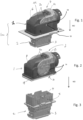
Fig. 1 is a schematic perspective view of an example of embodiment of an electrical connector assembly comprising a female and a male connectors mated together; -
Fig. 2 is a schematic perspective view of the female connector of the connector assembly ofFig. 1 , a portion of a side wall of the housing of this female connector being removed; -
Fig. 3 is a schematic perspective view of the male connector of the connector assembly ofFig. 1 ; -
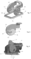
Fig. 4 is a schematic perspective view of the housing of the female connector ofFig. 2 , a portion of a side wall of the housing of this female connector being removed; -
Fig. 5 is a schematic perspective view of sealing means of the female connector ofFig. 2 ; -
Fig. 5 is a schematic perspective view of sealing means of the female connector ofFig. 2 ; -
Fig. 6 is a schematic perspective view of the housing of the female connector ofFig. 4 , with the sealing means ofFig. 5 overmolded on this housing; -
Fig. 7 is a schematic perspective view of the actuating lever of the female connector shown inFigs. 1 and 2 , with the sealing means shown inFig. 5 ; -
Fig. 8 is a schematic perspective view of a flange of the actuating lever shown inFig. 7 , with a polished area; -
Fig. 9 is a schematic perspective view of the electrical connector assembly shown inFig. 1 , with the lever in open position and the female and a male connectors in a "pre-position" (at the beginning of the mating operation), a portion of a side wall of the housing of this female connector being removed; -
Fig. 10 is similar toFigure 9 , with the cross-section of the side wall shifted outwards; -
Fig. 11 is a schematic cross-section (perpendicular to the mating face and parallel to the rotation axis) of the electrical connector assembly shown inFigs. 9 and10 ; -
Fig. 12 is similar toFigure 10 , with the lever in closed position and the female and a male connectors fully mated; and -
Fig. 13 is a cross-section, similar toFigure 11 , of the electrical connector assembly ofFig. 12 . - The disclosure illustrated in
Figs. 1 and 2 relates acable connector assembly 100. For example, thiscable connector assembly 100 is designed to connect cables (not shown) through an opening in aframe 35 of a car door or of a car body. - This cable connector comprises a connector 1 and a
counter-connector 2. The connector 1 and thecounter-connector 2 are intended to be mated in a mating direction MD and electrically connected together. - For example, the
counter-connector 2 is a male connector and comprises amale housing 3 intended to be fastened to the frame. Themale housing 3 is made of molded plastic and accommodates electrical male terminals (not shown). Themale housing 3 comprises two actuatingpins 4, each extending from a male housing side face 5 essentially perpendicular to the mating direction MD. - For example, the connector 1 is a female connector and comprises a
female housing 6. Thefemale housing 6 is made of molded plastic and accommodates electrical female terminals (not shown). An actuatinglever 7 is rotatably mounted onto thefemale housing 6 about a rotation axis RA essentially perpendicular to the mating direction MD. The actuatinglever 7 is made of molded plastic. In particular, the actuatinglever 7 comprises twopivots 29 aligned with the rotation axis RA. The actuatinglever 7 provides mate assist means. When the actuatinglever 7 is in open position, the female connector 1 can be mated with a counter-connector 2 (e.g., they can be brought closer to each other in "preposition"). When the actuatinglever 7 is in open position, the twolever arms 20 form an angle which is, for example, comprised between 40 and 90 degrees, for example close to 70 degrees. When the actuatinglever 7 is in closed position the female connector 1 is mated with acounter-connector 2. When the actuatinglever 7 is in closed position the twolever arms 20 form an angle which is, for example, comprised between 0 and 20 degrees with themating face 10, for example close to 0 degree. In the closed position, the actuatinglever 7 is flush with thefemale housing 6, taking up less space. - The
female housing 6 comprises a first femalehousing side face 8, a second female housing side face 9 and a mating face 10 (seeFig. 4 ). Themating face 10 is essentially perpendicular to the mating direction MD. The first femalehousing side face 8 and the second female housing side face 9 extend essentially parallel to the mating direction MD. Acompartment 11 is arranged over each of the firstfemale housing face 8 and the second female housing side face 9 respectively (seeFigs. 1 and11 ). Eachcompartment 11 partially covers a respective femalehousing side face 8, 9. Eachcompartment 11 comprises anexternal wall 32 and an internal wall 33 (SeeFig. 11 ). Theexternal wall 32 and theinternal wall 33 extend essentially perpendicular to the rotation axis RA. - A
concave surface 12 is formed inside each compartment 11 (SeeFig. 4 ). Eachconcave surface 12 extends along a portion of a first arc of a circle 13 centred on the rotation axis RA. - The
female housing 6 comprises guidingslots 18 longitudinally extending essentially perpendicular to themating face 10. When the female 1 and male 2 connectors are brought closer to each other in "preposition", each actuatingpin 4 engages a respective guiding slot 18 (SeeFig. 9 ). During the mating operation of the female 1 and male 2 connectors, each actuatingpin 4 moves along a respective guidingslot 18. Each guiding slot allows arespective pin 4 to pass through aninternal wall 33, so that eachrespective pin 4 can engage and cooperate with acam slot 28, thereby providing a mating assistance when the actuatinglever 7 is rotated from the open position to the closed position. - The connector 1 comprises sealing means 14 overmoulded on the female housing 6 (see
Figs. 2 ,5 and 6 for example). In other words, thefemale housing 6 is a two-component part. Indeed, thefemale housing 6 comprises ahard plastic portion 15 and the elastomeric sealing means 14 overmoulded on the hard plastic portion 15 (SeeFig. 6 ). The sealing means 14 comprises twolever seals 16 and an interfacial seal 17 (SeeFig. 5 ). Eachlever seal 16 is connected to theinterfacial seal 17. For example, eachlever seal 16 is connected to theinterfacial seal 17 through one of the guiding slots 18 (SeeFig. 6 ). - The
female housing 6 comprises bonding surfaces 31 on which thelever seal 16 is overmoulded (SeeFig. 4 ). - The
actuating lever 7 has twolever flanges 19 and twolever arms 20 respectively connecting onelever flange 19 to alever handle 21. Eachlever flange 19 is at least partially accommodated in a respective compartment 11 (InFigs 2 ,4 ,6 ,9 ,10 and 12 , theexternal wall 32 of acompartment 11, is removed in order to show one of theflanges 19 of the lever 7). This configuration prevents theflanges 19 from moving apart. Indeed, theflanges 19 are blocked in directions parallel to the rotation axis RA by theexternal walls 32 on the one hand and by theinternal walls 33 of the compartments on the other. Eachlever flange 19 has aninner face 22 facing a respective femalehousing side face 8, 9 (i.e., facing an internal wall 33) and anouter surface 30 facing an inner surface of the respective compartment 11 (i.e., facing the inner surface of an external wall 32). Eachpivot 29 extends from anouter surface 30. Eachpivot 29 engages a respective hole formed in the inner surface of therespective compartment 11. Eachlever flange 19 has aconvex surface 23 that extends along a portion of a second arc of acircle 24 centred on the rotation axis RA, when theactuating lever 7 is rotatably mounted on thefemale housing 6. - Each
lever seal 16 comprises at least onefirst portion 25 intercalated between at least a portion of saidconcave surface 12 and a portion of saidconvex surface 23, and at least onesecond portion 26 intercalated between eachinner face 22 of alever flange 19 and a portion of theinner wall 33 of a respective femalehousing side face 8, 9. Thefirst portion 25 andsecond portion 26 of the lever seals 16 are configured to form, between each inner faces 22 and the respective femalehousing side face 8, 9, a continuous sealing barrier around the rotation axis RA, at least when theactuating lever 7 is in closed position. In the example of embodiment shown in the figures, thefirst portion 25 andsecond portion 26 of the lever seals 16 are also configured to form, between each inner faces 22 and the respective femalehousing side face 8, 9, a continuous sealing barrier around the rotation axis RA, when theactuating lever 7 is in open position. Advantageously, eachinner face 22 of alever flange 19 has apolished area 27 onto which wipes said at least onesecond portion 22 of the sealing means 14. Thispolished area 27 extends all around acam slot 28 designed to engage theactuating pin 4 to assist coupling and uncoupling of the connector 1 and thecounter-connector 2. Thispolished area 27 promotes a better contact of thesecond portion 26 of eachlever seal 16 on eachlever flange 19 and improves tightness.Lips 34 may be provided on thesecond portion 26 to improve water tightness and/or dust-tightness. Thefirst portion 25 andsecond portion 26 of eachlever seal 16 form, between each inner faces 22 and the respective femalehousing side face 8, 9, a continuous sealing barrier around eachcam slot 28, at least when theactuating lever 7 is in closed position. In the example of embodiment shown in the figures, thefirst portion 25 andsecond portion 26 of eachlever seal 16 form, between each inner faces 22 and the respective femalehousing side face 8, 9, a continuous sealing barrier around eachcam slot 28, when theactuating lever 7 is in open position too. - As shown in
Figures 9 ,10 and 11 , thelever flanges 19 are sufficiently thick for thepins 4 to enter thecam slot 28, but thelever flanges 19 are in continuous contact with thefirst portions 25 on the second arcs of acircle 24. - As illustrated by
Figs. 10 and 11 , the sealing means 14 is already in place when the connector 1 and the counter-connector 2 are in preposition (i.e., with thelever 7 at 70°). And of course, the sealing means 14 the sealing is already in place when the connector 1 and the counter-connector 2 are fully mated (i.e., with thelever 7 at 0° - seeFigures 12 and 13 ). - As can be seen in
Figs. 11 and 13 , thecam slots 28, the guidingslots 18 and thepins 4 are located inside a watertight region delimited by the lever seals 14 and more particularly by its first 25 and second 26 portions.
Claims (11)
- An electrical female connector (1) with a female housing (6), a sealing means (14) being overmoulded on the female housing (6) and an actuating lever (7), wherein the female housing (6) has a mating face (10) and two female housing side faces (8, 9) on which the lever arm (7) is rotatably mounted about a rotation axis (RA) between an open position and a closed position,wherein the actuating lever (7) has two lever flanges (19) and two lever arms (20) respectively connecting each lever flange (20) to a lever handle (21), each lever flange (19) having an inner face (22) facing a respective female housing side face (8, 9),wherein each female housing side face (8, 9) has a concave surface (12) that extends along a portion of a first arc of a circle (13) centred on the rotation axis (RA),wherein each lever flange (19) has a convex surface (23) that extends along a portion of a second arc of a circle (24) centred on the rotation axis (RA), characterized in that the sealing means (14) comprises two lever seals (16), each comprising at least one first portion (25) intercalated between at least a portion of said concave surface (12) and a portion of said convex surface (23), and at least one second portion (26) intercalated between each inner face (22) and a respective female housing side face (8, 9), andin that the first portion (25) and second portion (26) of the lever seals (16) are configured to form, between each inner faces (22) and the respective female housing side face (8, 9), a continuous sealing barrier around the rotation axis (RA), at least when the actuating lever (7) is in closed position.
- The electrical connector according to claim 1, wherein each lever flange (19) comprises a cam slot (28), and the first portion (25) and second portion (26) of each lever seal (16) form, between each inner faces (22) and the respective female housing side face (8, 9), a continuous sealing barrier around each cam slot (28), at least when the actuating lever (7) is in closed position.
- The electrical connector according to claim 2, the first portion (25) and second portion (26) of each lever seal (16) form, a continuous sealing barrier around each cam slot (28), when the actuating lever (7) is in open position.
- The electrical connector according any one of the preceding claims, wherein each lever seal 16) is connected to an interfacial seal (17).
- The electrical connector according to claim 4, wherein the housing (6) has a guiding slot (18) longitudinally extending essentially perpendicular to the mating face (10) and each lever seal (16) is connected to the interfacial seal through the guiding slot (18).
- The electrical connector according to any one of the preceding claims, wherein each inner face (22) of the lever flanges (19) has c
- The electrical connector according to claim 6, wherein said at least one second portion (26) of the sealing means (14) has longitudinal lips (34) running along said at least one second portion (26) of the sealing means (14), and configured to slide on said polished area (27), when the lever is rotated between the closed and open positions and vice-versa.
- The electrical connector according any one of the preceding claims, wherein the two lever arms (20) form an angle comprised between 40 and 90 degrees with the mating face (10) when the actuating lever (7) is in open position in which the female connector (1) can be mated with a counter-connector (2).
- The electrical connector according any one of the preceding claims, wherein the two lever arms (20) form an angle comprised between 0 and 20 degrees with the mating face (10) when the actuating lever (7) is in closed position in which the female connector (1) is mated with a counter-connector (2).
- An electrical connector assembly (100), comprising a connector (1) according to any one of claims 1 to 7 and a counter-connector (2) mated to the connector (1), wherein the actuating lever (7) is in closed position with the two lever arms (20) forming an angle comprised between 0 and 20 degrees with the mating face (10), wherein the counter-connector (2) comprises two actuating pins (4), each actuating pin (4) extending from a side face (5) of the counter-connector (2), and wherein each actuating pin (4) is located inside a region delimited by said a continuous sealing barrier.
- The electrical connector assembly (100) of claim 10, wherein each actuating pin (4) passes through a guiding slot (18) located inside a region delimited by said a continuous sealing barrier.
Applications Claiming Priority (1)
| Application Number | Priority Date | Filing Date | Title |
|---|---|---|---|
| IN202341065539 | 2023-09-29 |
Publications (1)
| Publication Number | Publication Date |
|---|---|
| EP4531212A1 true EP4531212A1 (en) | 2025-04-02 |
Family
ID=92899418
Family Applications (1)
| Application Number | Title | Priority Date | Filing Date |
|---|---|---|---|
| EP24202333.1A Pending EP4531212A1 (en) | 2023-09-29 | 2024-09-24 | Sealed connector assembly |
Country Status (1)
| Country | Link |
|---|---|
| EP (1) | EP4531212A1 (en) |
Citations (3)
| Publication number | Priority date | Publication date | Assignee | Title |
|---|---|---|---|---|
| US20070197074A1 (en) * | 2004-04-07 | 2007-08-23 | Markus Gimbel | Sealed Plug Connection Through a Partition Wall And Method Of Fitting |
| EP3989370A1 (en) * | 2020-10-13 | 2022-04-27 | TE Connectivity Germany GmbH | Housing assembly for an electrical connector with an operating lever as well as electrical connector and connector assembly |
| US20220311184A1 (en) * | 2020-08-11 | 2022-09-29 | Aptiv Technologies Limited | Connector assembly with sealed symmetrical split lever |
-
2024
- 2024-09-24 EP EP24202333.1A patent/EP4531212A1/en active Pending
Patent Citations (3)
| Publication number | Priority date | Publication date | Assignee | Title |
|---|---|---|---|---|
| US20070197074A1 (en) * | 2004-04-07 | 2007-08-23 | Markus Gimbel | Sealed Plug Connection Through a Partition Wall And Method Of Fitting |
| US20220311184A1 (en) * | 2020-08-11 | 2022-09-29 | Aptiv Technologies Limited | Connector assembly with sealed symmetrical split lever |
| EP3989370A1 (en) * | 2020-10-13 | 2022-04-27 | TE Connectivity Germany GmbH | Housing assembly for an electrical connector with an operating lever as well as electrical connector and connector assembly |
Similar Documents
| Publication | Publication Date | Title |
|---|---|---|
| JP3570614B2 (en) | Connector assembly and its mounting method | |
| US7255581B2 (en) | Lever-type connector | |
| JP2934825B2 (en) | Electrical connector assembly with improved cam mechanism | |
| US5183408A (en) | Connector with fitting operation cam members | |
| JP6819903B2 (en) | Connector connection structure | |
| US6024605A (en) | Electrical connector with interlocking living hinge | |
| US8011938B2 (en) | Electrical connector having linear actuator | |
| US5810612A (en) | Electrical connector with cam lock lever | |
| EP1318570A1 (en) | A connector and method of assembling it | |
| EP3955395B1 (en) | Connector assembly with sealed symmetrical split lever | |
| US10490936B2 (en) | Connector cover and assembly structure of connector with connector cover | |
| JP5095431B2 (en) | Electrical connector | |
| EP4142068B1 (en) | Connector device | |
| JP2002352903A (en) | Lever-type connector | |
| EP1009065B1 (en) | Waterproof connector | |
| CN112531409A (en) | Connector assembly with connector position assurance member | |
| CN114665326A (en) | First connector, second connector and connector combination | |
| JP4084079B2 (en) | Connector structure | |
| US6656037B2 (en) | Connector | |
| US11139613B2 (en) | Connector assembly with automatic connection completion detection structure | |
| US11799240B2 (en) | Electrical connector with a lever locking member and mate assist mechanism | |
| EP3989370A1 (en) | Housing assembly for an electrical connector with an operating lever as well as electrical connector and connector assembly | |
| JP2025160522A (en) | Connectors with levers and connector systems with lever connectors | |
| US20210143580A1 (en) | Lever-type connector | |
| JP3991275B2 (en) | Wire cover |
Legal Events
| Date | Code | Title | Description |
|---|---|---|---|
| PUAI | Public reference made under article 153(3) epc to a published international application that has entered the european phase |
Free format text: ORIGINAL CODE: 0009012 |
|
| STAA | Information on the status of an ep patent application or granted ep patent |
Free format text: STATUS: THE APPLICATION HAS BEEN PUBLISHED |
|
| AK | Designated contracting states |
Kind code of ref document: A1 Designated state(s): AL AT BE BG CH CY CZ DE DK EE ES FI FR GB GR HR HU IE IS IT LI LT LU LV MC ME MK MT NL NO PL PT RO RS SE SI SK SM TR |
|
| STAA | Information on the status of an ep patent application or granted ep patent |
Free format text: STATUS: REQUEST FOR EXAMINATION WAS MADE |
|
| 17P | Request for examination filed |
Effective date: 20250929 |