EP4531209A1 - Connector assembly and structure comprising the same - Google Patents
Connector assembly and structure comprising the same Download PDFInfo
- Publication number
- EP4531209A1 EP4531209A1 EP24191897.8A EP24191897A EP4531209A1 EP 4531209 A1 EP4531209 A1 EP 4531209A1 EP 24191897 A EP24191897 A EP 24191897A EP 4531209 A1 EP4531209 A1 EP 4531209A1
- Authority
- EP
- European Patent Office
- Prior art keywords
- flexible board
- connector assembly
- fixed member
- center terminal
- signal line
- Prior art date
- Legal status (The legal status is an assumption and is not a legal conclusion. Google has not performed a legal analysis and makes no representation as to the accuracy of the status listed.)
- Granted
Links
Images






Classifications
-
- H—ELECTRICITY
- H01—ELECTRIC ELEMENTS
- H01R—ELECTRICALLY-CONDUCTIVE CONNECTIONS; STRUCTURAL ASSOCIATIONS OF A PLURALITY OF MUTUALLY-INSULATED ELECTRICAL CONNECTING ELEMENTS; COUPLING DEVICES; CURRENT COLLECTORS
- H01R12/00—Structural associations of a plurality of mutually-insulated electrical connecting elements, specially adapted for printed circuits, e.g. printed circuit boards [PCB], flat or ribbon cables, or like generally planar structures, e.g. terminal strips, terminal blocks; Coupling devices specially adapted for printed circuits, flat or ribbon cables, or like generally planar structures; Terminals specially adapted for contact with, or insertion into, printed circuits, flat or ribbon cables, or like generally planar structures
- H01R12/70—Coupling devices
- H01R12/7005—Guiding, mounting, polarizing or locking means; Extractors
- H01R12/7011—Locking or fixing a connector to a PCB
- H01R12/7047—Locking or fixing a connector to a PCB with a fastener through a screw hole in the coupling device
-
- H—ELECTRICITY
- H01—ELECTRIC ELEMENTS
- H01R—ELECTRICALLY-CONDUCTIVE CONNECTIONS; STRUCTURAL ASSOCIATIONS OF A PLURALITY OF MUTUALLY-INSULATED ELECTRICAL CONNECTING ELEMENTS; COUPLING DEVICES; CURRENT COLLECTORS
- H01R12/00—Structural associations of a plurality of mutually-insulated electrical connecting elements, specially adapted for printed circuits, e.g. printed circuit boards [PCB], flat or ribbon cables, or like generally planar structures, e.g. terminal strips, terminal blocks; Coupling devices specially adapted for printed circuits, flat or ribbon cables, or like generally planar structures; Terminals specially adapted for contact with, or insertion into, printed circuits, flat or ribbon cables, or like generally planar structures
- H01R12/50—Fixed connections
- H01R12/59—Fixed connections for flexible printed circuits, flat or ribbon cables or like structures
- H01R12/592—Fixed connections for flexible printed circuits, flat or ribbon cables or like structures connections to contact elements
-
- H—ELECTRICITY
- H01—ELECTRIC ELEMENTS
- H01R—ELECTRICALLY-CONDUCTIVE CONNECTIONS; STRUCTURAL ASSOCIATIONS OF A PLURALITY OF MUTUALLY-INSULATED ELECTRICAL CONNECTING ELEMENTS; COUPLING DEVICES; CURRENT COLLECTORS
- H01R12/00—Structural associations of a plurality of mutually-insulated electrical connecting elements, specially adapted for printed circuits, e.g. printed circuit boards [PCB], flat or ribbon cables, or like generally planar structures, e.g. terminal strips, terminal blocks; Coupling devices specially adapted for printed circuits, flat or ribbon cables, or like generally planar structures; Terminals specially adapted for contact with, or insertion into, printed circuits, flat or ribbon cables, or like generally planar structures
- H01R12/70—Coupling devices
- H01R12/7005—Guiding, mounting, polarizing or locking means; Extractors
- H01R12/7011—Locking or fixing a connector to a PCB
- H01R12/7064—Press fitting
-
- H—ELECTRICITY
- H01—ELECTRIC ELEMENTS
- H01R—ELECTRICALLY-CONDUCTIVE CONNECTIONS; STRUCTURAL ASSOCIATIONS OF A PLURALITY OF MUTUALLY-INSULATED ELECTRICAL CONNECTING ELEMENTS; COUPLING DEVICES; CURRENT COLLECTORS
- H01R24/00—Two-part coupling devices, or either of their cooperating parts, characterised by their overall structure
- H01R24/38—Two-part coupling devices, or either of their cooperating parts, characterised by their overall structure having concentrically or coaxially arranged contacts
- H01R24/40—Two-part coupling devices, or either of their cooperating parts, characterised by their overall structure having concentrically or coaxially arranged contacts specially adapted for high frequency
- H01R24/50—Two-part coupling devices, or either of their cooperating parts, characterised by their overall structure having concentrically or coaxially arranged contacts specially adapted for high frequency mounted on a PCB [Printed Circuit Board]
-
- H—ELECTRICITY
- H01—ELECTRIC ELEMENTS
- H01R—ELECTRICALLY-CONDUCTIVE CONNECTIONS; STRUCTURAL ASSOCIATIONS OF A PLURALITY OF MUTUALLY-INSULATED ELECTRICAL CONNECTING ELEMENTS; COUPLING DEVICES; CURRENT COLLECTORS
- H01R12/00—Structural associations of a plurality of mutually-insulated electrical connecting elements, specially adapted for printed circuits, e.g. printed circuit boards [PCB], flat or ribbon cables, or like generally planar structures, e.g. terminal strips, terminal blocks; Coupling devices specially adapted for printed circuits, flat or ribbon cables, or like generally planar structures; Terminals specially adapted for contact with, or insertion into, printed circuits, flat or ribbon cables, or like generally planar structures
- H01R12/70—Coupling devices
- H01R12/77—Coupling devices for flexible printed circuits, flat or ribbon cables or like structures
- H01R12/771—Details
- H01R12/774—Retainers
-
- H—ELECTRICITY
- H01—ELECTRIC ELEMENTS
- H01R—ELECTRICALLY-CONDUCTIVE CONNECTIONS; STRUCTURAL ASSOCIATIONS OF A PLURALITY OF MUTUALLY-INSULATED ELECTRICAL CONNECTING ELEMENTS; COUPLING DEVICES; CURRENT COLLECTORS
- H01R2103/00—Two poles
-
- H—ELECTRICITY
- H01—ELECTRIC ELEMENTS
- H01R—ELECTRICALLY-CONDUCTIVE CONNECTIONS; STRUCTURAL ASSOCIATIONS OF A PLURALITY OF MUTUALLY-INSULATED ELECTRICAL CONNECTING ELEMENTS; COUPLING DEVICES; CURRENT COLLECTORS
- H01R4/00—Electrically-conductive connections between two or more conductive members in direct contact, i.e. touching one another; Means for effecting or maintaining such contact; Electrically-conductive connections having two or more spaced connecting locations for conductors and using contact members penetrating insulation
- H01R4/28—Clamped connections, spring connections
- H01R4/30—Clamped connections, spring connections utilising a screw or nut clamping member
- H01R4/34—Conductive members located under head of screw
-
- H—ELECTRICITY
- H01—ELECTRIC ELEMENTS
- H01R—ELECTRICALLY-CONDUCTIVE CONNECTIONS; STRUCTURAL ASSOCIATIONS OF A PLURALITY OF MUTUALLY-INSULATED ELECTRICAL CONNECTING ELEMENTS; COUPLING DEVICES; CURRENT COLLECTORS
- H01R9/00—Structural associations of a plurality of mutually-insulated electrical connecting elements, e.g. terminal strips or terminal blocks; Terminals or binding posts mounted upon a base or in a case; Bases therefor
- H01R9/03—Connectors arranged to contact a plurality of the conductors of a multiconductor cable, e.g. tapping connections
- H01R9/05—Connectors arranged to contact a plurality of the conductors of a multiconductor cable, e.g. tapping connections for coaxial cables
- H01R9/0515—Connection to a rigid planar substrate, e.g. printed circuit board
Definitions
- This invention relates to a connector assembly comprising a coaxial connector configured to be attached to a coaxial cable.
- a coaxial connector configured to be attached to a coaxial cable is disclosed in JP2009-064588A (Patent Document 1), the content of which is incorporated herein by reference.
- Patent Document 1 discloses a coaxial connector 90 fixed to a case 94.
- the case 94 is provided with a board (circuit board) 96 located therein.
- the board 96 is a rigid circuit board 96 which is hardly bent.
- the circuit board 96 is formed with a transmission line (signal line) 98.
- the coaxial connector 90 comprises a terminal portion (center terminal) 92.
- the center terminal 92 is electrically connected with the signal line 98 of the circuit board 96.
- the electrical connection as described above is usually performed by soldering the center terminal 92 to the signal line 98.
- the flexible board of some instances is made of material having low heat resistance. In these instances, it is difficult to solder the center terminal of the coaxial connector to the signal line of the flexible board. Moreover, when the center terminal is attempted to be pressed against the signal line instead of the soldering, the flexible board might be bent, and thereby sufficient contact pressure could not be obtained. As a result, contact reliability between the center terminal and the signal line might be lowered.
- An aspect of the present invention provides a connector assembly configured to be connected to a flexible board.
- the flexible board extends along a horizontal plane, the flexible board is formed with two passing holes. Each of the passing holes passes through the flexible board in an up-down direction perpendicular to the horizontal plane.
- the flexible board has an upper surface which is formed with a signal line.
- the signal line extends in a front-rear direction perpendicular to the up-down direction and is located between the two passing holes in a lateral direction perpendicular to both the up-down direction and the front-rear direction.
- the connector assembly comprises a coaxial connector, a fixed member and two fixing members.
- the coaxial connector is configured to be attached to a front end of a coaxial cable.
- the coaxial connector comprises an outer terminal, a center terminal and an insulation member.
- the insulation member insulates the outer terminal and the center terminal from each other.
- the outer terminal has an end surface and two projecting portions. The two projecting portions are apart from each other in the lateral direction and project forward from the end surface.
- the center terminal has a contact portion. The contact portion is located between the two projecting portions in the lateral direction and extends forward beyond the end surface.
- the fixed member has a pressed portion. The fixed member is located below the flexible board under a connected state where the connector assembly is connected to the flexible board.
- the two fixing members are fixed to the two projecting portions of the outer terminal through the two passing holes of the flexible board, respectively, while pressing the pressed portion of the fixed member against a lower surface of a part of the flexible bard on which the signal line is formed, and thereby the contact portion of the center terminal is pressed against and is in contact with the signal line of the flexible board.
- Another aspect of the present invention provides a structure comprising the connector assembly and the flexible board.
- the flexible board is located between the projecting portions and the fixed member in the up-down direction.
- the signal line of the flexible board is pressed by the fixed member from below and is pressed against the contact portion of the center terminal.
- the center terminal of the coaxial connector can be pressed against and connected to the signal line of the flexible board with no soldering.
- the fixing members press the fixed member against the flexible board when the center terminal is connected to the signal line.
- The-thus pressed fixed member reduces the bending of a part of the flexible board located between the center terminal and the signal line, and thereby contact reliability between the center terminal and the signal line can be improved.
- an aspect of the invention provides a configuration in which the coaxial connector is connected to the flexible board and which enables high contact reliability between the center terminal and the signal line.
- a structure 10 according to an embodiment of the present invention comprises a connector assembly 12 and a flexible board 16.
- the flexible board 16 extends along a horizontal plane.
- the connector assembly 12 is configured to be connected to the flexible board 16.
- the connector assembly 12 is configured to be connected to a rear end of the flexible board 16 in a front-rear direction in parallel to the horizontal plane.
- the connector assembly 12 of Fig. 2 is under a connected state where the connector assembly 12 is connected to the flexible board 16.
- the connector assembly 12 of Fig. 1 is under a pre-connected state where the connector assembly 12 is not yet connected to the flexible board 16.
- the horizontal plane of the present embodiment is the XY-plane.
- the front-rear direction of the present embodiment is the X-direction.
- "forward” means the positive X-direction
- "rearward” means the negative X-direction.
- the words such as the horizontal plane and the front-rear direction do not indicate the absolute positional relation relative to the ground but merely indicate a relative positional relation under a definition where the flexible board 16 extends in the horizontal plane when not bent at all, and where the connector assembly 12 is located forward of this flexible board 16.
- the flexible board 16 comprises a base 70.
- the base 70 is formed of a thin film-like insulator having a thickness of about 0.1 mm.
- the illustrated flexible board 16 comprises only the base 70 except for various conductive patterns formed on the base 70.
- the flexible board 16 comprises no unbendable member such as a reinforcement plate configured to reinforce the base 70.
- the thus-formed flexible board 16 is easily bent when receiving a force.
- the easily bendable flexible board 16 can be flexibly arranged in a narrow space in an apparatus (not shown).
- the flexible board 16 of the present embodiment is wholly thin and is easily bendable.
- the present invention is not limited thereto.
- an unillustrated front part of the flexible board 16 may be reinforced by a reinforcement plate.
- Only the illustrated rear end of the flexible board 16 which is configured to be connected to the connector assembly 12 may be formed of only the thin and easily bendable base 70 and various conductive patterns.
- the flexible board 16 has an upper surface 70U and a lower surface 70L in an up-down direction perpendicular to the horizontal plane.
- the upper surface 70U and the lower surface 70L are located at an upper end and a lower end of the base 70, respectively.
- the up-down direction of the present embodiment is the Z-direction. In the present embodiment, “upward” means the positive Z-direction, and “downward” means the negative Z-direction.
- the flexible board 16 is formed with two passing holes 72.
- Each of the passing holes 72 passes through the flexible board 16 in the up-down direction.
- Each of the passing holes 72 has a circular shape in the horizontal plane.
- the thus-formed passing holes 72 are used when the connector assembly 12 is screwed to the flexible board 16 as described later.
- the two passing holes 72 are apart from each other in a lateral direction perpendicular to both the front-rear direction and the up-down direction and are located at positions same as each other in the front-rear direction.
- the lateral direction of the present embodiment is the Y-direction.
- the passing holes 72 of the present embodiment are formed as described above. However, the present invention is not limited thereto.
- the shape of each of the passing holes 72 is not specifically limited.
- the number of the passing holes 72 may be three or more. In this instance, two of the passing holes 72 may be apart from each other in the lateral direction and may be located at positions same as each other in the front-rear direction.
- the upper surface 70U of the flexible board 16 is formed with a signal line 74 which is a conductive pattern.
- the signal line 74 extends in the front-rear direction and is located between the two passing holes 72 in the lateral direction.
- the lower surface 70L of the flexible board 16 is formed with a ground layer (not shown) which is a conductive pattern and covers the whole of the lower surface 70L.
- the signal line 74 of an instance is connected to an antenna which is formed on an unillustrated front end part of the flexible board 16.
- the connector assembly 12 under the connected state transmits signals to the antenna through the signal line 74.
- the thus-transmitted signals are sent outward from the antenna.
- signals received by the antenna are transmitted to the connector assembly 12 through the signal line 74.
- the structure 10 of the present embodiment is uses as described above, for example.
- the structure 10 of the present embodiment is an antenna device.
- the usage of the structure 10 of the present invention is not specifically limited.
- the structure 10 of the present invention may be any electric device with the flexible board 16.
- the flexible board 16 of the present embodiment has the aforementioned configuration.
- the configuration of the flexible board 16 can be modified in accordance with the usage of the structure 10.
- the ground layer (not shown) may be partially formed on the lower surface 70L.
- the connector assembly 12 of the present embodiment comprises a coaxial connector 20, a fixed member 40 made of metal and two fixing members (screws) 60 each made of metal.
- the connector assembly 12 of the present embodiment comprises only the aforementioned members.
- the present invention is not limited thereto.
- the connector assembly 12 may further comprise another member in addition to the aforementioned members.
- the coaxial connector 20 of the present embodiment is configured to be attached to a front end of a coaxial cable 80.
- the coaxial connector 20 of the present embodiment is a so-called sub miniature type A (SMA) connector.
- SMA sub miniature type A
- the present invention is not limited thereto but applicable to various coaxial connectors 20.
- the coaxial connector 20 of the present embodiment comprises a center terminal 21 made of conductor, an insulation member 22 made of insulator and an outer terminal 24 made of conductor.
- the coaxial connector 20 of the present embodiment comprises only the aforementioned members. However, the present invention is not limited thereto.
- the coaxial connector 20 may further comprise another member in addition to the aforementioned members.
- the center terminal 21 of the present embodiment extends along the front-rear direction and has a body 212, a contact portion 214 and a connection portion 218.
- the body 212 is a middle part of the center terminal 21 in the front-rear direction.
- the contact portion 214 extends forward from the body 212.
- the connection portion 218 has a socket shape and extends rearward from the body 212.
- the center terminal 21 is electrically connected with the core wire 82 of the coaxial cable 80 when the coaxial connector 20 is attached to the coaxial cable 80.
- the connection portion 218 of the center terminal 21 is configured to be electrically connected with the core wire 82.
- the center terminal 21 and the core wire 82 connected to each other transmit signals to each other.
- the insulation member 22 of the present embodiment comprises a front insulation member 222 and a rear insulation member 224.
- the front insulation member 222 is combined with the rear insulation member 224 and is located forward of the rear insulation member 224.
- the insulation member 22 of the present embodiment consists of the aforementioned two members.
- the present invention is not limited thereto.
- the front insulation member 222 and the rear insulation member 224 may be a member integrally formed with each other.
- the outer terminal 24 of the present embodiment comprises a front conductive member 242 and a rear conductive member 244.
- the front conductive member 242 is combined with the rear conductive member 244 and is located forward of the rear conductive member 244.
- the front conductive member 242 is in contact with the rear conductive member 244.
- the outer terminal 24 of the present embodiment consists of the aforementioned two members.
- the present invention is not limited thereto.
- the front conductive member 242 and the rear conductive member 244 may be a member integrally formed with each other.
- the outer terminal 24 is electrically connected with the shield 86 of the coaxial cable 80 when the coaxial connector 20 is attached to the coaxial cable 80.
- the rear conductive member 244 of the outer terminal 24 is configured to be electrically connected with the shield 86.
- the outer terminal 24 and the shield 86 connected to each other have ground potentials same as each other.
- the insulation member 22 encloses the body 212 and the connection portion 218 of the center terminal 21 except for a front end part of the body 212 in a vertical plane (YZ-plane) perpendicular to the front-rear direction.
- the outer terminal 24 encloses the front end part of the body 212 in the YZ-plane with a distance formed therebetween and encloses the insulation member 22 in the YZ-plane.
- the thus-arranged insulation member 22 is located between the center terminal 21 and the outer terminal 24 in the YZ-plane. In other words, the insulation member 22 insulates the outer terminal 24 and the center terminal 21 from each other.
- the center terminal 21, the insulation member 22 and the outer terminal 24 of the present embodiment are arrange as described above. However, the arrangement of the center terminal 21, the insulation member 22 and the outer terminal 24 is not specifically limited, provided that the outer terminal 24 and the center terminal 21 are insulated from each other by the insulation member 22.
- the outer terminal 24 has an end surface 26 and two projecting portions 27.
- the end surface 26 of the present embodiment is a front surface of the front conductive member 242 and a flat circular surface in parallel to the YZ-plane.
- the two projecting portions 27 are apart from each other in the lateral direction and project forward from the end surface 26.
- the two projecting portions 27 of the present embodiment have a mirror symmetric shape with respect to a predetermined plane (XZ-plane).
- the thus-arranged two projecting portions 27 are located at positions same as each other in the up-down direction.
- Each of the two projecting portions 27 has a rectangular flat-plate shape in parallel to the horizontal plane and has an upper surface 27U and a lower surface 27L.
- Each of the upper surfaces 27U and the lower surfaces 27L is a flat surface in parallel to the horizontal plane.
- the outer terminal 24 of the present embodiment is formed with a center hole 29.
- the center hole 29 has a circular shape in the YZ-plane.
- the center hole 29 is located at the center of the end surface 26 in the YZ-plane and opens forward.
- the two projecting portions 27 are located at opposite sides of the end surface 26, respectively, with the center hole 29 located therebetween.
- the center terminal 21 is located at the center of the center hole 29 in the YZ-plane.
- the body 212 of the center terminal 21 has a circular shape in the YZ-plane.
- the contact portion 214 of the center terminal 21 has a circular shape which is smaller than that of the body 212 in the YZ-plane.
- the center hole 29 extends from the end surface 26 to a front end of the front insulation member 222 in the front-rear direction.
- the front end part of the body 212 of the center terminal 21 is located in the center hole 29.
- the contact portion 214 of the center terminal 21 is located forward of the end surface 26. Referring to Fig. 3 , the contact portion 214 is located between the two projecting portions 27 in the lateral direction and extends forward beyond the end surface 26.
- the end surface 26, the projecting portions 27 and the contact portion 214 of the present embodiment have the aforementioned configurations and are arranged as described above.
- the present invention is not limited thereto, but the configurations and the arrangement of the end surface 26, the projecting portions 27 and the contact portion 214 can be modified as necessary.
- each of the projecting portions 27 of the present embodiment is formed with a screw hole 28.
- Each of the screw holes 28 of the present embodiment passes through the projecting portion 27 in the up-down direction.
- the screw holes 28 are provided at positions which correspond to those of the passing holes 72 of the flexible board 16 in the horizontal plane, respectively.
- the thus-arranged two screw holes 28 are apart from each other in the lateral direction and are located at positions same as each other in the front-rear direction.
- the number of the screw holes 28 of the present embodiment is two.
- each of the projecting portions 27 may be formed with two or more of the screw holes 28.
- Each of the screw holes 28 may be a hole with a ceiling.
- the fixed member 40 of the present embodiment has a rectangular flat-plate shape in parallel to the horizontal plane. In the horizontal plane, the fixed member 40 has long sides each extending in the lateral direction and short sides each extending in the front-rear direction.
- the fixed member 40 has an upper surface 40U and a lower surface 40L. Each of the upper surface 40U and the lower surface 40L of the present embodiment is a flat surface in parallel to the horizontal plane.
- the fixed member 40 has a pressed portion 42.
- the pressed portion 42 is a part which is configured to be pressed against the flexible board 16 under the connected state (see Fig. 5 ).
- a middle part of the upper surface 40U in the lateral direction mainly works as the pressed portion 42.
- the fixed member 40 of the present embodiment is formed with two fixing holes 45.
- Each of the fixing holes 45 passes through the fixed member 40 in the up-down direction.
- Each of the fixing holes 45 has a circular shape in the horizontal plane.
- the fixing holes 45 are provided at positions which correspond to those of the passing holes 72 of the flexible board 16 in the horizontal plane, respectively.
- the thus-arranged two fixing holes 45 are apart from each other in the lateral direction and are located at positions same as each other in the front-rear direction.
- the fixed member 40 of the present embodiment has the aforementioned configuration.
- the present invention is not limited thereto.
- the shape of each of the fixing holes 45 is not specifically limited.
- the number of the fixing holes 45 may be three or more.
- the two fixing members 60 of the present embodiment have shapes same as each other. More specifically, each of the fixing members 60 of the present embodiment is a screw 60. Accordingly, each of the fixing members 60 is formed with a thread (not shown).
- the fixing members 60 are provided so that they correspond to the passing holes 72 of the flexible board 16, respectively. Accordingly, the number of the fixing members 60 of the present embodiment is two.
- the connector assembly 12 may be provided with three or more of the fixing members 60 which have shapes different from each other.
- the connector assembly 12 of the present embodiment is configured to be connected to the flexible board 16 by a connection method described below.
- the connection method described below is merely an example and can be modified as necessary.
- the coaxial connector 20, the flexible board 16 and the fixed member 40 are arranged from top to bottom in this order while the screw holes 28 of the coaxial connector 20, the passing holes 72 of the flexible board 16 and the fixing holes 45 of the fixed member 40 are arranged at positions same as each other in the horizontal plane. Then, each of the fixing members 60 is screwed into the screw hole 28 through the fixing hole 45 and the passing hole 72.
- the flexible board 16 is sandwiched and held between the lower surfaces 27L of the two projecting portions 27 of the coaxial connector 20 and the upper surface 40U of the fixed member 40 in the up-down direction.
- the thus-arranged connector assembly 12 is under the connected state shown in Figs. 2 to 6 , and the contact portion 214 of the center terminal 21 is located just over the signal line 74 of the flexible board 16.
- the fixed member 40 is located below the flexible board 16 under the connected state. Under the connected state, the head of each of the fixing members 60 is pressed against the lower surface 40L of the fixed member 40 which is in parallel to the horizontal plane and presses the fixed member 40 upward.
- the upper surface 40U of the thus-pressed fixed member 40 extends in parallel to the horizontal plane and presses the flexible board 16 against the lower surfaces 27L of the projecting portions 27 which are in parallel to the horizontal plane.
- the flexible board 16 is sandwiched and held between the projecting portions 27 and the fixed member 40 while keeping its posture in which the flexible board 16 extends in parallel to the horizontal plane.
- the thus- sandwiched flexible board 16 has a contact region which is located under the contact portion 214 of the center terminal 21.
- the pressed portion 42 of the fixed member 40 is pressed against the contact region of the flexible board 16 and supports the contact region from below.
- the thus-supported contact region of the flexible board 16 is not bent even when a force is applied thereto from above.
- a structure 10A according to a first modification comprises a connector assembly 12A different from the connector assembly 12 and a flexible board 16A different from the flexible board 16.
- the connector assembly 12A is configured to be connected to the flexible board 16A similarly to the connector assembly 12.
- the upper end of the pressed portion 42A of the present modification is pressed against the lower surface 70L of a part of the bendable portion 79A of the flexible board 16A on which the signal line 74 is formed.
- the bendable portion 79A is bent so as to protrude upward when an upward force is applied thereto from the pressed portion 42A.
- the signal line 74 formed on the bendable portion 79A is moved upward.
- the pressed portion 42A is resiliently deformed downward.
- the signal line 74 which is moved upward is pressed against the contact portion 214A of the center terminal 21A of the coaxial connector 20A.
- the present modification similarly to the previously described embodiment, provides a configuration in which the coaxial connector 20A is connected to the flexible board 16A and which enables high contact reliability between the center terminal 21A and the signal line 74.
- the pressed portion 42A of the fixed member 40A is located between the two fixing holes 45A in the lateral direction similarly to the previously described embodiment.
- each of the fixing members 60 is screwed into the screw hole 28 of the projecting portion 27 through the fixing hole 45A of the fixed member 40A and the passing hole 72 of the flexible board 16A under the connected state.
- the pressed portion 42A can be stably pressed against the flexible board 16A in a simple manner according to this connection method.
- the connector assembly 12A forms the structure 10A together with the flexible board 16A connected thereto.
- the flexible board 16A of the structure 10A is located between the projecting portions 27 of the outer terminal 24 and the fixed member 40A in the up-down direction.
- the upward protruding pressed portion 42A of the fixed member 40A is pressed against a part of the flexible board 16A which corresponds to the signal line 74 in the front-rear direction.
- the signal line 74 of the flexible board 16A is pressed by the fixed member 40A from below and is pressed against the contact portion 214A of the center terminal 21A.
- a structure 10B according to a second modification comprises a connector assembly 12B different from the connector assembly 12A and the flexible board 16A same as that of the structure 10A.
- the connector assembly 12B comprises a coaxial connector 20B different from the coaxial connector 20A and comprises the fixed member 40A and the two fixing members 60 same as those of the connector assembly 12A.
- the coaxial connector 20B comprises a center terminal 21B different from the center terminal 21A of the coaxial connector 20A.
- the coaxial connector 20B has the configuration same as that of the coaxial connector 20A except for the center terminal 21B.
- the center terminal 21B has a contact portion 214B different from the contact portion 214A of the center terminal 21A.
- the center terminal 21B has the configuration same as that of the center terminal 21A except for the contact portion 214B.
- the contact reliability between the center terminal 21B and the signal line 74 can be improved without bending the contact portion 214B downward similarly to the first modification.
- the cylindrical contact portion 214B can be reliably in contact with the signal line 74 even if the front conductive member 242 of the outer terminal 24 rotates beyond a designed position in the YZ-plane during the process of combining the front conductive member 242 with the rear conductive member 244.
- the structure 10B can be easily made and can be reduced in height by providing the contact portion 214B of a simple cylindrical shape.
- the connector assembly 12C comprises a coaxial connector 20C different from the coaxial connector 20 and a connection member 40C which is not provided to the connector assembly 12.
- the connection member 40C is a single metal plate with bends.
- the connection member 40C according to the present modification has a predetermined portion which works as a fixed member 41C and two portions other than the predetermined portion which work as fixing members 46C.
- the thus-formed connector assembly 12C comprises the coaxial connector 20C different from the coaxial connector 20, the fixed member 41C different from the fixed member 40 and the two fixing members 46C different from the fixing members 60.
- Each of the fixed member 41C and the fixing members 46C of the present modification is a part of the connection member 40C. In other words, the fixed member 41C and the two fixing members 46C are integrally formed with each other.
- connection member 40C has a coupling portion (fixed member) 41C, a pressed portion 42C, two arc-like portions 43C and two press-fit portions (fixing members) 46C.
- the coupling portion 41C works as the fixed member 41C
- each of the press-fit portions 46C works as the fixing member 46C.
- the fixed member 41C of the present modification is the coupling portion 41C
- each of the fixing members 46C of the present modification is the press-fit portion 46C.
- the two press-fit portions 46C are located at opposite sides of the connection member 40C in the lateral direction, respectively.
- the coupling portion 41C couples the two press-fit portions 46C together in the lateral direction.
- each of the press-fit portions 46C is connected to the coupling portion 41C via the arc-like portion 43C.
- Each of the arc-like portions 43C has an arc-like shape which projects downward in the YZ-plane.
- the coupling portion 41C extends along the horizontal plane and has an upper surface 40U and a lower surface 40L each of which is a flat surface in parallel to the horizontal plane. According to the present modification, a middle part of the upper surface 40U of the coupling portion 41C in the lateral direction mainly works as the pressed portion 42C. In other words, the fixed member 41C has the pressed portion 42C.
- the connector assembly 12C is configured to be connected to the flexible board 16 not by the connection method of the connector assembly 12 in which the screws 60 are screwed but by another connection method in which the press-fit portions 46C are press-fit.
- each of the press-fit portions 46C is inserted into the press-fit hole 28C of the coaxial connector 20C through the passing hole 72 of the flexible board 16.
- Each of the press-fit holes 28C has a size in the front-rear direction which is smaller than another size of the press-fit portion 46C in the front-rear direction. Accordingly, each of the press-fit portions 46C is inserted into the press-fit hole 28C while being compressed in the front-rear direction.
- the press-fit portion 46C received in each of the press-fit holes 28C is pressed against an inner wall surface of the press-fit hole 28C by its restoring force.
- the connection member 40C is fixed to the coaxial connector 20C, and the connector assembly 12C is connected to the flexible board 16.
- the fixed member 41C of the connection member 40C is located below the flexible board 16 under a connected state where the connector assembly 12C is connected to the flexible board 16.
- the two fixing members 46C of the connection member 40C are fixed to the two projecting portions 27C of the outer terminal 24C through the two passing holes 72 of the flexible board 16, respectively, while pressing the pressed portion 42C of the fixed member 41C against the lower surface 70L of a part of the flexible board 16 on which the signal line 74 is formed, and thereby the contact portion 214 of the center terminal 21 is pressed against and is brought into contact with the signal line 74 of the flexible board 16.
- the present modification similarly to the previously described embodiment, provides a configuration in which the coaxial connector 20C is connected to the flexible board 16 and which enables high contact reliability between the center terminal 21 and the signal line 74.
- each of the press-fit portions 46C is press-fit into the press-fit hole 28C through the passing hole 72 of the flexible board 16 under the connected state.
- the connection method using the press-fitting can be easily performed in a short time in comparison with the connection method using the screwing.
- the arc-like portions 43C When the two arc-like portions 43C is pressed upward during the process of press-fitting the press-fit portions 46C into the press-fit holes 28C, the arc-like portions 43C are resiliently deformed, and thereby the pressed portion 42C receives an upward force. According to this mechanism, the contact reliability between the center terminal 21 and the signal line 74 can be further improved.
- the present invention is not limited thereto.
- the arc-like portions 43C may be provided as necessary.
- the connector assembly 12C forms the structure 10C together with the flexible board 16 connected thereto.
- the flexible board 16 of the structure 10C is located between the projecting portions 27C of the outer terminal 24C and the fixed member 41C in the up-down direction.
- the signal line 74 of the flexible board 16 is pressed by the fixed member 41C from below and is pressed against the contact portion 214 of the center terminal 21.
- the structure 10C may comprise the flexible board 16A instead of the flexible board 16.
- the fixed member 41C is provided with a part such as the upward protruding pressed portion 42A of the fixed member 40A.
Landscapes
- Coupling Device And Connection With Printed Circuit (AREA)
- Multi-Conductor Connections (AREA)
- Connections By Means Of Piercing Elements, Nuts, Or Screws (AREA)
Abstract
Description
- This invention relates to a connector assembly comprising a coaxial connector configured to be attached to a coaxial cable.
- For example, a coaxial connector configured to be attached to a coaxial cable is disclosed in
JP2009-064588A - Referring to
Fig. 20 , Patent Document 1 discloses acoaxial connector 90 fixed to acase 94. Thecase 94 is provided with a board (circuit board) 96 located therein. As can be seen fromFig. 20 , theboard 96 is arigid circuit board 96 which is hardly bent. Thecircuit board 96 is formed with a transmission line (signal line) 98. Thecoaxial connector 90 comprises a terminal portion (center terminal) 92. Thecenter terminal 92 is electrically connected with thesignal line 98 of thecircuit board 96. The electrical connection as described above is usually performed by soldering thecenter terminal 92 to thesignal line 98. - There is a demand for connecting the
coaxial connector 90 to a thin, easily bendable flexible board instead of a circuit board which is hardly bent. However, the flexible board of some instances is made of material having low heat resistance. In these instances, it is difficult to solder the center terminal of the coaxial connector to the signal line of the flexible board. Moreover, when the center terminal is attempted to be pressed against the signal line instead of the soldering, the flexible board might be bent, and thereby sufficient contact pressure could not be obtained. As a result, contact reliability between the center terminal and the signal line might be lowered. - It is therefore an object of the present invention to provide a configuration in which a coaxial connector is connected to a flexible board and which enables high contact reliability between a center terminal of a coaxial connector and a signal line of a flexible board.
- An aspect of the present invention provides a connector assembly configured to be connected to a flexible board. The flexible board extends along a horizontal plane, the flexible board is formed with two passing holes. Each of the passing holes passes through the flexible board in an up-down direction perpendicular to the horizontal plane. The flexible board has an upper surface which is formed with a signal line. The signal line extends in a front-rear direction perpendicular to the up-down direction and is located between the two passing holes in a lateral direction perpendicular to both the up-down direction and the front-rear direction. The connector assembly comprises a coaxial connector, a fixed member and two fixing members. The coaxial connector is configured to be attached to a front end of a coaxial cable. The coaxial connector comprises an outer terminal, a center terminal and an insulation member. The insulation member insulates the outer terminal and the center terminal from each other. The outer terminal has an end surface and two projecting portions. The two projecting portions are apart from each other in the lateral direction and project forward from the end surface. The center terminal has a contact portion. The contact portion is located between the two projecting portions in the lateral direction and extends forward beyond the end surface. The fixed member has a pressed portion. The fixed member is located below the flexible board under a connected state where the connector assembly is connected to the flexible board. Under the connected state, the two fixing members are fixed to the two projecting portions of the outer terminal through the two passing holes of the flexible board, respectively, while pressing the pressed portion of the fixed member against a lower surface of a part of the flexible bard on which the signal line is formed, and thereby the contact portion of the center terminal is pressed against and is in contact with the signal line of the flexible board.
- Another aspect of the present invention provides a structure comprising the connector assembly and the flexible board. The flexible board is located between the projecting portions and the fixed member in the up-down direction. The signal line of the flexible board is pressed by the fixed member from below and is pressed against the contact portion of the center terminal.
- According to an aspect of the present invention, the center terminal of the coaxial connector can be pressed against and connected to the signal line of the flexible board with no soldering. The fixing members press the fixed member against the flexible board when the center terminal is connected to the signal line. The-thus pressed fixed member reduces the bending of a part of the flexible board located between the center terminal and the signal line, and thereby contact reliability between the center terminal and the signal line can be improved. Thus, an aspect of the invention provides a configuration in which the coaxial connector is connected to the flexible board and which enables high contact reliability between the center terminal and the signal line.
- An appreciation of the objectives of the present invention and a more complete understanding of its configuration may be had by studying the following description of the preferred embodiment and by referring to the accompanying drawings.
-
-
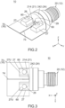
Fig. 1 is a perspective view showing a connector assembly according to an embodiment of the present invention, wherein the connector assembly is under a pre-connected state where the connector assembly is not yet connected to a flexible board. -
Fig. 2 is a perspective view showing the connector assembly ofFig. 1 , wherein the connector assembly is under a connected state where the connector assembly is connected to the flexible board. -
Fig. 3 is a top view showing the connector assembly ofFig. 2 . -
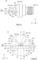
Fig. 4 is a side view showing the connector assembly ofFig. 2 , wherein outlines of a hidden fixing hole, a hidden passing hole and a hidden screw hole are illustrated with dashed line. -
Fig. 5 is a front view showing the connector assembly ofFig. 2 , wherein outlines of the hidden fixing holes, the hidden passing holes and the hidden screw holes are illustrated with dashed line. -
Fig. 6 is a cross-sectional view showing the connector assembly ofFig. 5 , taken along line VI-VI, wherein a coaxial cable and a mating connector are partially illustrated with dashed line, a part of the connector assembly enclosed by chain dotted line is enlarged and illustrated, and in the enlarged view, an outline of a center terminal under the pre-connected state is illustrated with dashed line. -
Fig. 7 is a perspective view showing a modification of the flexible board ofFig. 1 . -
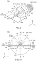
Fig. 8 is a perspective view showing a modification of the connector assembly ofFig. 1 , wherein the connector assembly is under the pre-connected state. -
Fig. 9 is a perspective view showing the connector assembly ofFig. 8 , wherein the connector assembly is under the connected state. -
Fig. 10 is a front view showing the connector assembly ofFig. 9 , wherein outlines of hidden fixing holes, hidden passing holes and hidden screw holes are illustrated with dashed line. -
Fig. 11 is a cross-sectional view showing the connector assembly ofFig. 10 , taken along line XI-XI, wherein a part of the connector assembly enclosed by dashed line is enlarged and illustrated. -
Fig. 12 is a front view showing a part of the connector assembly enclosed by two-dot chain line A ofFig. 10 , wherein a hidden part of a pressed portion of a fixed member is illustrated with dashed line. -
Fig. 13 is a perspective view showing another modification of the connector assembly ofFig. 1 , wherein the connector assembly is under the connected state. -
Fig. 14 is a front view showing a part of the connector assembly ofFig. 13 , wherein the illustrated part corresponds to the part illustrated inFig. 12 , and a hidden part of the pressed portion of the fixed member is illustrated with dashed line. -
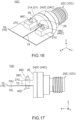
Fig. 15 is a perspective view showing still another modification of the connector assembly ofFig. 1 , wherein the connector assembly is under the pre-connected state. -
Fig. 16 is a perspective view showing the connector assembly ofFig. 15 , wherein the connector assembly is under the connected state. -
Fig. 17 is a side view showing the connector assembly ofFig. 16 , wherein outlines of a hidden passing hole and a hidden press-fit hole are illustrated with dashed line. -
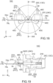
Fig. 18 is a front view showing the connector assembly ofFig. 16 , wherein outlines of the hidden passing holes and the hidden press-fit holes are illustrated with dashed line. -
Fig. 19 is a cross-sectional view showing the connector assembly ofFig. 18 , taken along line XIX-XIX. -
Fig. 20 is a perspective view showing a coaxial connector, a case and a board of Patent Document 1. - While the invention is susceptible to various modifications and alternative forms, specific embodiments thereof are shown by way of example in the drawings and will herein be described in detail. It should be understood, however, that the drawings and detailed description thereto are not intended to limit the invention to the particular form disclosed, but on the contrary, the intention is to cover all modifications, equivalents and alternatives falling within the spirit and scope of the present invention as defined by the appended claims.
- Referring to
Fig. 1 , astructure 10 according to an embodiment of the present invention comprises aconnector assembly 12 and aflexible board 16. Theflexible board 16 extends along a horizontal plane. As shown inFig. 2 , theconnector assembly 12 is configured to be connected to theflexible board 16. In detail, theconnector assembly 12 is configured to be connected to a rear end of theflexible board 16 in a front-rear direction in parallel to the horizontal plane. Theconnector assembly 12 ofFig. 2 is under a connected state where theconnector assembly 12 is connected to theflexible board 16. Theconnector assembly 12 ofFig. 1 is under a pre-connected state where theconnector assembly 12 is not yet connected to theflexible board 16. - The horizontal plane of the present embodiment is the XY-plane. The front-rear direction of the present embodiment is the X-direction. In the present embodiment, "forward" means the positive X-direction, and "rearward" means the negative X-direction. The words such as the horizontal plane and the front-rear direction do not indicate the absolute positional relation relative to the ground but merely indicate a relative positional relation under a definition where the
flexible board 16 extends in the horizontal plane when not bent at all, and where theconnector assembly 12 is located forward of thisflexible board 16. - Referring to
Fig. 1 , theflexible board 16 comprises abase 70. Thebase 70 is formed of a thin film-like insulator having a thickness of about 0.1 mm. The illustratedflexible board 16 comprises only the base 70 except for various conductive patterns formed on thebase 70. Theflexible board 16 comprises no unbendable member such as a reinforcement plate configured to reinforce thebase 70. The thus-formedflexible board 16 is easily bent when receiving a force. The easily bendableflexible board 16 can be flexibly arranged in a narrow space in an apparatus (not shown). - The
flexible board 16 of the present embodiment is wholly thin and is easily bendable. However, the present invention is not limited thereto. For example, an unillustrated front part of theflexible board 16 may be reinforced by a reinforcement plate. Only the illustrated rear end of theflexible board 16 which is configured to be connected to theconnector assembly 12 may be formed of only the thin and easilybendable base 70 and various conductive patterns. - The
flexible board 16 has anupper surface 70U and alower surface 70L in an up-down direction perpendicular to the horizontal plane. Theupper surface 70U and thelower surface 70L are located at an upper end and a lower end of thebase 70, respectively. The up-down direction of the present embodiment is the Z-direction. In the present embodiment, "upward" means the positive Z-direction, and "downward" means the negative Z-direction. - The
flexible board 16 is formed with two passingholes 72. Each of the passing holes 72 passes through theflexible board 16 in the up-down direction. Each of the passing holes 72 has a circular shape in the horizontal plane. The thus-formed passing holes 72 are used when theconnector assembly 12 is screwed to theflexible board 16 as described later. The two passingholes 72 are apart from each other in a lateral direction perpendicular to both the front-rear direction and the up-down direction and are located at positions same as each other in the front-rear direction. The lateral direction of the present embodiment is the Y-direction. - The passing holes 72 of the present embodiment are formed as described above. However, the present invention is not limited thereto. For example, the shape of each of the passing holes 72 is not specifically limited. Moreover, the number of the passing holes 72 may be three or more. In this instance, two of the passing holes 72 may be apart from each other in the lateral direction and may be located at positions same as each other in the front-rear direction.
- The
upper surface 70U of theflexible board 16 is formed with asignal line 74 which is a conductive pattern. Thesignal line 74 extends in the front-rear direction and is located between the two passingholes 72 in the lateral direction. Thelower surface 70L of theflexible board 16 is formed with a ground layer (not shown) which is a conductive pattern and covers the whole of thelower surface 70L. - Referring to
Fig. 2 , thesignal line 74 of an instance is connected to an antenna which is formed on an unillustrated front end part of theflexible board 16. In this instance, theconnector assembly 12 under the connected state transmits signals to the antenna through thesignal line 74. The thus-transmitted signals are sent outward from the antenna. On the other hand, signals received by the antenna are transmitted to theconnector assembly 12 through thesignal line 74. Thestructure 10 of the present embodiment is uses as described above, for example. In other words, thestructure 10 of the present embodiment is an antenna device. However, the usage of thestructure 10 of the present invention is not specifically limited. Thestructure 10 of the present invention may be any electric device with theflexible board 16. - The
flexible board 16 of the present embodiment has the aforementioned configuration. However, the configuration of theflexible board 16 can be modified in accordance with the usage of thestructure 10. For example, the ground layer (not shown) may be partially formed on thelower surface 70L. - Referring to
Fig. 1 , theconnector assembly 12 of the present embodiment comprises acoaxial connector 20, a fixedmember 40 made of metal and two fixing members (screws) 60 each made of metal. Theconnector assembly 12 of the present embodiment comprises only the aforementioned members. However, the present invention is not limited thereto. For example, theconnector assembly 12 may further comprise another member in addition to the aforementioned members. - Hereafter, explanation will be made about the
coaxial connector 20, the fixedmember 40 and the fixingmembers 60 of the present embodiment in this order. - Referring to
Fig. 6 , thecoaxial connector 20 of the present embodiment is configured to be attached to a front end of acoaxial cable 80. Thecoaxial connector 20 of the present embodiment is a so-called sub miniature type A (SMA) connector. However, the present invention is not limited thereto but applicable to variouscoaxial connectors 20. - The
coaxial cable 80 illustrated with dashed line is a typical coaxial cable and comprises acore wire 82 made of conductor, aninner insulator 84 made of insulator and covering thecore wire 82, ashield 86 made of conductor and covering theinner insulator 84 and asheath 88 made of insulator and covering theshield 86. The number of thecore wire 82 of the present embodiment is one. The configuration of thecoaxial cable 80 is not specifically limited, provided that the number of thecore wire 82 is one. For example, theshield 86 may be a braid formed of fine metal wires or may be made of metal foil. For example, thecoaxial cable 80 may be connected to a rear end of thecoaxial connector 20 via amating connector 89 attached to thecoaxial cable 80. - Referring to
Fig. 6 together withFig. 1 , thecoaxial connector 20 of the present embodiment comprises acenter terminal 21 made of conductor, aninsulation member 22 made of insulator and anouter terminal 24 made of conductor. Thecoaxial connector 20 of the present embodiment comprises only the aforementioned members. However, the present invention is not limited thereto. For example, thecoaxial connector 20 may further comprise another member in addition to the aforementioned members. - As shown in
Fig. 6 , thecenter terminal 21 of the present embodiment extends along the front-rear direction and has abody 212, acontact portion 214 and aconnection portion 218. Thebody 212 is a middle part of thecenter terminal 21 in the front-rear direction. Thecontact portion 214 extends forward from thebody 212. Theconnection portion 218 has a socket shape and extends rearward from thebody 212. Thecenter terminal 21 is electrically connected with thecore wire 82 of thecoaxial cable 80 when thecoaxial connector 20 is attached to thecoaxial cable 80. In detail, theconnection portion 218 of thecenter terminal 21 is configured to be electrically connected with thecore wire 82. Thecenter terminal 21 and thecore wire 82 connected to each other transmit signals to each other. - The
center terminal 21 of the present embodiment has the aforementioned configuration. However, the configuration of thecenter terminal 21 can be modified as necessary, provided that thecenter terminal 21 has thecontact portion 214 which extends along the front-rear direction. - The
insulation member 22 of the present embodiment comprises afront insulation member 222 and arear insulation member 224. Thefront insulation member 222 is combined with therear insulation member 224 and is located forward of therear insulation member 224. Theinsulation member 22 of the present embodiment consists of the aforementioned two members. However, the present invention is not limited thereto. For example, thefront insulation member 222 and therear insulation member 224 may be a member integrally formed with each other. - As shown in
Figs. 1 and6 , theouter terminal 24 of the present embodiment comprises a frontconductive member 242 and a rearconductive member 244. The frontconductive member 242 is combined with the rearconductive member 244 and is located forward of the rearconductive member 244. The frontconductive member 242 is in contact with the rearconductive member 244. Theouter terminal 24 of the present embodiment consists of the aforementioned two members. However, the present invention is not limited thereto. For example, the frontconductive member 242 and the rearconductive member 244 may be a member integrally formed with each other. - Referring to
Fig. 6 , theouter terminal 24 is electrically connected with theshield 86 of thecoaxial cable 80 when thecoaxial connector 20 is attached to thecoaxial cable 80. In detail, the rearconductive member 244 of theouter terminal 24 is configured to be electrically connected with theshield 86. Theouter terminal 24 and theshield 86 connected to each other have ground potentials same as each other. - The
insulation member 22 encloses thebody 212 and theconnection portion 218 of thecenter terminal 21 except for a front end part of thebody 212 in a vertical plane (YZ-plane) perpendicular to the front-rear direction. Theouter terminal 24 encloses the front end part of thebody 212 in the YZ-plane with a distance formed therebetween and encloses theinsulation member 22 in the YZ-plane. The thus-arrangedinsulation member 22 is located between thecenter terminal 21 and theouter terminal 24 in the YZ-plane. In other words, theinsulation member 22 insulates theouter terminal 24 and thecenter terminal 21 from each other. Thecenter terminal 21, theinsulation member 22 and theouter terminal 24 of the present embodiment are arrange as described above. However, the arrangement of thecenter terminal 21, theinsulation member 22 and theouter terminal 24 is not specifically limited, provided that theouter terminal 24 and thecenter terminal 21 are insulated from each other by theinsulation member 22. - As shown in
Figs. 1 ,3 and5 , theouter terminal 24 has anend surface 26 and two projectingportions 27. Theend surface 26 of the present embodiment is a front surface of the frontconductive member 242 and a flat circular surface in parallel to the YZ-plane. The two projectingportions 27 are apart from each other in the lateral direction and project forward from theend surface 26. The two projectingportions 27 of the present embodiment have a mirror symmetric shape with respect to a predetermined plane (XZ-plane). The thus-arranged two projectingportions 27 are located at positions same as each other in the up-down direction. Each of the two projectingportions 27 has a rectangular flat-plate shape in parallel to the horizontal plane and has anupper surface 27U and alower surface 27L. Each of theupper surfaces 27U and thelower surfaces 27L is a flat surface in parallel to the horizontal plane. - As shown in
Figs. 1 and5 , theouter terminal 24 of the present embodiment is formed with acenter hole 29. Thecenter hole 29 has a circular shape in the YZ-plane. Thecenter hole 29 is located at the center of theend surface 26 in the YZ-plane and opens forward. The two projectingportions 27 are located at opposite sides of theend surface 26, respectively, with thecenter hole 29 located therebetween. Thecenter terminal 21 is located at the center of thecenter hole 29 in the YZ-plane. Thebody 212 of thecenter terminal 21 has a circular shape in the YZ-plane. Thecontact portion 214 of thecenter terminal 21 has a circular shape which is smaller than that of thebody 212 in the YZ-plane. - Referring to
Fig. 6 , thecenter hole 29 extends from theend surface 26 to a front end of thefront insulation member 222 in the front-rear direction. The front end part of thebody 212 of thecenter terminal 21 is located in thecenter hole 29. Thecontact portion 214 of thecenter terminal 21 is located forward of theend surface 26. Referring toFig. 3 , thecontact portion 214 is located between the two projectingportions 27 in the lateral direction and extends forward beyond theend surface 26. - The
end surface 26, the projectingportions 27 and thecontact portion 214 of the present embodiment have the aforementioned configurations and are arranged as described above. However, the present invention is not limited thereto, but the configurations and the arrangement of theend surface 26, the projectingportions 27 and thecontact portion 214 can be modified as necessary. - As shown in
Fig. 1 , each of the projectingportions 27 of the present embodiment is formed with ascrew hole 28. Each of the screw holes 28 of the present embodiment passes through the projectingportion 27 in the up-down direction. The screw holes 28 are provided at positions which correspond to those of the passing holes 72 of theflexible board 16 in the horizontal plane, respectively. The thus-arranged twoscrew holes 28 are apart from each other in the lateral direction and are located at positions same as each other in the front-rear direction. The number of the screw holes 28 of the present embodiment is two. However, the present invention is not limited thereto. For example, each of the projectingportions 27 may be formed with two or more of the screw holes 28. Each of the screw holes 28 may be a hole with a ceiling. - The fixed
member 40 of the present embodiment has a rectangular flat-plate shape in parallel to the horizontal plane. In the horizontal plane, the fixedmember 40 has long sides each extending in the lateral direction and short sides each extending in the front-rear direction. The fixedmember 40 has anupper surface 40U and alower surface 40L. Each of theupper surface 40U and thelower surface 40L of the present embodiment is a flat surface in parallel to the horizontal plane. - The fixed
member 40 has a pressedportion 42. As described later, the pressedportion 42 is a part which is configured to be pressed against theflexible board 16 under the connected state (seeFig. 5 ). According to the present embodiment, a middle part of theupper surface 40U in the lateral direction mainly works as the pressedportion 42. - The fixed
member 40 of the present embodiment is formed with two fixingholes 45. Each of the fixing holes 45 passes through the fixedmember 40 in the up-down direction. Each of the fixing holes 45 has a circular shape in the horizontal plane. The fixing holes 45 are provided at positions which correspond to those of the passing holes 72 of theflexible board 16 in the horizontal plane, respectively. The thus-arranged two fixingholes 45 are apart from each other in the lateral direction and are located at positions same as each other in the front-rear direction. - The fixed
member 40 of the present embodiment has the aforementioned configuration. However, the present invention is not limited thereto. For example, the shape of each of the fixing holes 45 is not specifically limited. Moreover, the number of the fixing holes 45 may be three or more. - The two fixing
members 60 of the present embodiment have shapes same as each other. More specifically, each of the fixingmembers 60 of the present embodiment is ascrew 60. Accordingly, each of the fixingmembers 60 is formed with a thread (not shown). The fixingmembers 60 are provided so that they correspond to the passing holes 72 of theflexible board 16, respectively. Accordingly, the number of the fixingmembers 60 of the present embodiment is two. However, the present invention is not limited thereto. For example, theconnector assembly 12 may be provided with three or more of the fixingmembers 60 which have shapes different from each other. - Referring to
Fig. 1 , theconnector assembly 12 of the present embodiment is configured to be connected to theflexible board 16 by a connection method described below. The connection method described below is merely an example and can be modified as necessary. - Firstly, the
coaxial connector 20, theflexible board 16 and the fixedmember 40 are arranged from top to bottom in this order while the screw holes 28 of thecoaxial connector 20, the passingholes 72 of theflexible board 16 and the fixing holes 45 of the fixedmember 40 are arranged at positions same as each other in the horizontal plane. Then, each of the fixingmembers 60 is screwed into thescrew hole 28 through the fixinghole 45 and the passinghole 72. - Referring to
Figs. 4 and 5 , as a result of the aforementioned screwing, theflexible board 16 is sandwiched and held between thelower surfaces 27L of the two projectingportions 27 of thecoaxial connector 20 and theupper surface 40U of the fixedmember 40 in the up-down direction. Referring toFig. 3 , the thus-arrangedconnector assembly 12 is under the connected state shown inFigs. 2 to 6 , and thecontact portion 214 of thecenter terminal 21 is located just over thesignal line 74 of theflexible board 16. - Referring to
Fig. 5 , the fixedmember 40 is located below theflexible board 16 under the connected state. Under the connected state, the head of each of the fixingmembers 60 is pressed against thelower surface 40L of the fixedmember 40 which is in parallel to the horizontal plane and presses the fixedmember 40 upward. Theupper surface 40U of the thus-pressedfixed member 40 extends in parallel to the horizontal plane and presses theflexible board 16 against thelower surfaces 27L of the projectingportions 27 which are in parallel to the horizontal plane. As a result, theflexible board 16 is sandwiched and held between the projectingportions 27 and the fixedmember 40 while keeping its posture in which theflexible board 16 extends in parallel to the horizontal plane. The thus- sandwichedflexible board 16 has a contact region which is located under thecontact portion 214 of thecenter terminal 21. The pressedportion 42 of the fixedmember 40 is pressed against the contact region of theflexible board 16 and supports the contact region from below. The thus-supported contact region of theflexible board 16 is not bent even when a force is applied thereto from above. - Referring to
Figs. 3 and5 , thecontact portion 214 of thecenter terminal 21 is brought into contact with thesignal line 74 of theflexible board 16 under the connected state. Referring toFig. 6 , thecontact portion 214 of thecenter terminal 21 of the present embodiment is bent downward, for example, after thecoaxial connector 20 is assembled. The thus-bent contact portion 214 extends forward and downward under the pre-connected state shown inFig. 1 . A lower end of thecontact portion 214 is located below thelower surfaces 27L of the projectingportions 27 under the pre-connected state. The thus-formedcontact portion 214 is brought into abutment with thesignal line 74 of theflexible board 16 and is resiliently deformed under the connected state shown inFig. 6 . This resilient deformation generates a restoring force which presses thecontact portion 214 against thesignal line 74, which is supported to be unbendable, from above. - Summarizing the explanation described above, under the connected state, the two fixing
members 60 are fixed to the two projectingportions 27 of theouter terminal 24 through the two passingholes 72 of theflexible board 16, respectively, while pressing the pressedportion 42 of the fixedmember 40 against thelower surface 70L of a part of theflexible board 16 on which thesignal line 74 is formed, and thereby thecontact portion 214 of thecenter terminal 21 is pressed against and is brought into contact with thesignal line 74 of theflexible board 16. - As can be seen from the aforementioned mechanism, according to the present embodiment, the
center terminal 21 of thecoaxial connector 20 can be pressed against and connected to thesignal line 74 of theflexible board 16 with no soldering. The fixingmembers 60 press the fixedmember 40 against theflexible board 16 when thecenter terminal 21 is connected to thesignal line 74. The thus-pressedfixed member 40 reduces the bending of a part of theflexible board 16 located between thecenter terminal 21 and thesignal line 74, and thereby contact reliability between thecenter terminal 21 and thesignal line 74 can be improved. Thus, the present embodiment provides a configuration in which thecoaxial connector 20 is connected to theflexible board 16 and which enables high contact reliability between thecenter terminal 21 and thesignal line 74. - According to the present embodiment, the pressed
portion 42 of the fixedmember 40 is located between the two fixingholes 45 in the lateral direction. Moreover, as previously described, each of the fixingmembers 60 is screwed into thescrew hole 28 through the fixinghole 45 of the fixedmember 40 and the passinghole 72 of theflexible board 16 under the connected state. The pressedportion 42 can be stably pressed against theflexible board 16 in a simple manner according to this connection method. Thus, the contact reliability between thecenter terminal 21 and thesignal line 74 can be further improved. However, the present invention is not limited thereto, but the connection method of theconnector assembly 12 can be modified as necessary. - Referring to
Fig. 4 , theouter terminal 24 is grounded to the ground layer (not shown) of thelower surface 70L of theflexible board 16 via the projectingportions 27, the fixingmembers 60 and the fixedmember 40 under the connected state. However, the present invention is not limited thereto. For example, referring toFig. 7 together withFig. 1 , aflexible board 16X may be used instead of theflexible board 16. - The
flexible board 16X according to a modification comprises twolands 76X each of which is a conductive pattern and which are not provided on theflexible board 16. The two passingholes 72 pass through thelands 76X, respectively. Each of thelands 76X is formed with a plurality of viaholes 77X. Each of the via holes 77X passes through thebase 70 and theland 76X in the up-down direction, and thereby each of thelands 76X is electrically connected with the ground layer (not shown) of thelower surface 70L. Referring toFig. 7 together withFig. 4 , theouter terminal 24 under the connected state can be grounded to the ground layer of theflexible board 16X via the projectingportions 27 and thelands 76X by using theflexible board 16X. - Referring to
Fig. 5 , theconnector assembly 12 forms thestructure 10 together with theflexible board 16 connected thereto. Theflexible board 16 of thestructure 10 is located between the projectingportions 27 of theouter terminal 24 and the fixedmember 40 in the up-down direction. Thesignal line 74 of theflexible board 16 is pressed by the fixedmember 40 from below and is pressed against thecontact portion 214 of thecenter terminal 21. - The
structure 10 of the present embodiment can be further variously modified in addition to the already explained various modifications. Hereafter, explanation will be made about three modifications of thestructure 10, focusing on differences from thestructure 10. - Comparing
Fig. 8 withFig. 1 , astructure 10A according to a first modification comprises aconnector assembly 12A different from theconnector assembly 12 and aflexible board 16A different from theflexible board 16. ComparingFig. 9 withFig. 2 , theconnector assembly 12A is configured to be connected to theflexible board 16A similarly to theconnector assembly 12. - Comparing
Fig. 8 withFig. 1 , theflexible board 16A has a configuration similar to that of theflexible board 16. For example, theflexible board 16A extends along the horizontal plane (XY-plane). Theflexible board 16A is formed with two passingholes 72. Each of the passing holes 72 passes through theflexible board 16A in the up-down direction (Z-direction). Theflexible board 16A has anupper surface 70U which is formed with asignal line 74. Thesignal line 74 extends in the front-rear direction (X-direction) and is located between the two passingholes 72 in the lateral direction (Y-direction). - The
flexible board 16A is formed with twoslits 78A which are not formed in theflexible board 16. Each of theslits 78A is a cut which passes through theflexible board 16A in the up-down direction. The twoslits 78A are apart from each other in the lateral direction. Each of theslits 78A extends forward from a rear edge of theflexible board 16A. Thesignal line 74 is located between the twoslits 78A in the lateral direction and extends in the front-rear direction. - The
flexible board 16A has abendable portion 79A. Thebendable portion 79A is a part of theflexible board 16A which is located between the twoslits 78A in the lateral direction. The thus-arrangedbendable portion 79A is easily bendable. Thebendable portion 79A extends forward from the rear edge of theflexible board 16A. Thesignal line 74 is located at the middle of thebendable portion 79A in the lateral direction. - The
connector assembly 12A comprises acoaxial connector 20A different from thecoaxial connector 20, a fixedmember 40A different from the fixedmember 40 and the two fixingmembers 60 same as those of theconnector assembly 12. Thus, each of the fixingmembers 60 is thescrew 60. - The
coaxial connector 20A comprises acenter terminal 21A different from thecenter terminal 21. Thecoaxial connector 20A has the configuration same as that of thecoaxial connector 20 except for thecenter terminal 21A. Thecenter terminal 21A has acontact portion 214A different from thecontact portion 214. Thecenter terminal 21A has the configuration same as that of thecenter terminal 21 except for thecontact portion 214A. - Referring to
Fig. 11 together withFig. 6 , thecoaxial connector 20A is configured to be attached to the front end of thecoaxial cable 80. Referring toFig. 11 , thecoaxial connector 20A comprises theouter terminal 24, thecenter terminal 21A and theinsulation member 22. Theinsulation member 22 insulates theouter terminal 24 and thecenter terminal 21A from each other. As shown inFig. 8 , theouter terminal 24 has theend surface 26 and the two projectingportions 27. The two projectingportions 27 are apart from each other in the lateral direction and project forward from theend surface 26. Each of the projectingportions 27 is formed with thescrew hole 28. Thecontact portion 214A of thecenter terminal 21A is located between the two projectingportions 27 in the lateral direction and extends forward beyond theend surface 26. - Referring to
Figs. 10 and12 , thecontact portion 214A of thecenter terminal 21A has a fan shape in the YZ-plane perpendicular to the front-rear direction. The shape of thecontact portion 214A is different from that of the contact portion 214 (seeFig. 5 ) of thecenter terminal 21 in the aforementioned feature. In detail, the upper part of thecontact portion 214A has an arc-like shape which projects upward, and the lower part of thecontact portion 214A has a triangle shape which projects downward. The thus-formedcontact portion 214A has a lower end which projects downward. Referring toFig. 11 , the lower end of thecontact portion 214A is located slightly above thelower surfaces 27L of the projectingportions 27 under a pre-connected state where theconnector assembly 12A is not yet connected to theflexible board 16A as shown inFig. 8 . - Referring to
Fig. 8 , the fixedmember 40A is a single metal plate with bends. The fixedmember 40A has acoupling portion 41 A, a pressedportion 42A and twoside portions 44A. Moreover, the fixedmember 40A has anupper surface 40U and alower surface 40L. Each of theside portions 44A has a rectangular flat-plate shape in parallel to the horizontal plane. Each of theupper surface 40U and thelower surface 40L of each of the thus-formedside portions 44A is a flat surface in parallel to the horizontal plane. The twoside portions 44A are located at opposite sides of the fixedmember 40A in the lateral direction, respectively. Thecoupling portion 41A couples the twoside portions 44A together in the lateral direction. - According to the present modification, a middle part of the
upper surface 40U of thecoupling portion 41A in the lateral direction works as the pressedportion 42A. The pressedportion 42A protrudes upward. More specifically, the pressedportion 42A has an arc-like shape which projects upward in the YZ-plane. The pressedportion 42A has an upper end which is located above theupper surfaces 40U of theside portions 44A. - Comparing
Fig. 8 withFig. 1 , each of theside portions 44A is formed with a fixinghole 45A. Thus, the fixedmember 40A is formed with the two fixingholes 45A. Each of the fixingholes 45A has a size which is smaller than that of the fixinghole 45 in the up-down direction. The fixing holes 45A have configurations similar to those of the fixing holes 45 and are arranged similarly to the fixing holes 45 except for this difference. For example, each of the fixingholes 45A passes through the fixedmember 40A in the up-down direction. The fixing holes 45A are provided at positions which correspond to those of the passing holes 72 of theflexible board 16A in the horizontal plane, respectively. - Referring to
Figs. 10 and11 together withFig. 12 , theconnector assembly 12A is configured to be connected to theflexible board 16A by a connection method similar to that of the connector assembly 12 (seeFig. 2 ), or by the screwing with thescrews 60. - The fixed
member 40A is located below theflexible board 16A under a connected state where theconnector assembly 12A is connected to theflexible board 16A. Under the connected state, the two fixingmembers 60 are fixed to the two projectingportions 27 of theouter terminal 24 through the two passingholes 72 of theflexible board 16A, respectively, while pressing the pressedportion 42A of the fixedmember 40A against thelower surface 70L of a part of theflexible board 16A on which thesignal line 74 is formed, and thereby thecontact portion 214A of thecenter terminal 21A is pressed against and is brought into contact with thesignal line 74 of theflexible board 16A. - Referring to
Fig. 12 together withFig. 8 , under the connected state, the upper end of the pressedportion 42A of the present modification is pressed against thelower surface 70L of a part of thebendable portion 79A of theflexible board 16A on which thesignal line 74 is formed. Thebendable portion 79A is bent so as to protrude upward when an upward force is applied thereto from the pressedportion 42A. As a result, thesignal line 74 formed on thebendable portion 79A is moved upward. Meanwhile, the pressedportion 42A is resiliently deformed downward. Thesignal line 74 which is moved upward is pressed against thecontact portion 214A of thecenter terminal 21A of thecoaxial connector 20A. The present modification, similarly to the previously described embodiment, provides a configuration in which thecoaxial connector 20A is connected to theflexible board 16A and which enables high contact reliability between thecenter terminal 21A and thesignal line 74. - According to the present modification, the downward projecting lower end of the fan shape of the
contact portion 214A of thecenter terminal 21A is pressed against thesignal line 74 which is moved upward. Accordingly, the contact reliability between thecenter terminal 21A and thesignal line 74 can be improved without bending thecontact portion 214A downward. Moreover, the fan-like contact portion 214A can be reliably in contact with thesignal line 74 even if the frontconductive member 242 of theouter terminal 24 rotates beyond a designed position in the YZ-plane by an angle within a predetermined range during a process of combining the frontconductive member 242 with the rearconductive member 244. However, the present invention is not limited thereto. For example, thecontact portion 214A may extend forward and downward under the pre-connected state shown inFig. 8 . - Referring to
Fig. 10 , according to the present modification, the pressedportion 42A of the fixedmember 40A is located between the two fixingholes 45A in the lateral direction similarly to the previously described embodiment. Similarly to the previously described embodiment, each of the fixingmembers 60 is screwed into thescrew hole 28 of the projectingportion 27 through the fixinghole 45A of the fixedmember 40A and the passinghole 72 of theflexible board 16A under the connected state. The pressedportion 42A can be stably pressed against theflexible board 16A in a simple manner according to this connection method. - The
connector assembly 12A forms thestructure 10A together with theflexible board 16A connected thereto. Theflexible board 16A of thestructure 10A is located between the projectingportions 27 of theouter terminal 24 and the fixedmember 40A in the up-down direction. The upward protruding pressedportion 42A of the fixedmember 40A is pressed against a part of theflexible board 16A which corresponds to thesignal line 74 in the front-rear direction. As a result, thesignal line 74 of theflexible board 16A is pressed by the fixedmember 40A from below and is pressed against thecontact portion 214A of thecenter terminal 21A. - According to the present modification, the fixed
member 40A can be reduced in size in the up-down direction. Thus, according to the present modification, the contact reliability between thecenter terminal 21A and thesignal line 74 can be improved while thestructure 10A is reduced in height. - Referring to
Fig. 1 together withFig. 8 , thestructure 10 of the previously described embodiment may also comprise theflexible board 16A instead of theflexible board 16. However, no specific effects can be obtained unless the fixedmember 40 is provided with a part such as the upward protruding pressedportion 42A of the fixedmember 40A. In other words, in an instance in which thebendable portion 79A such as that of theflexible board 16A is provided, the upward protruding pressedportion 42A is preferred to be provided. In an instance in which the upward protruding pressedportion 42A is provided, thebendable portion 79A is preferred to be provided. - Comparing
Figs. 13 and 14 withFigs. 9 and12 , astructure 10B according to a second modification comprises aconnector assembly 12B different from theconnector assembly 12A and theflexible board 16A same as that of thestructure 10A. Theconnector assembly 12B comprises acoaxial connector 20B different from thecoaxial connector 20A and comprises the fixedmember 40A and the two fixingmembers 60 same as those of theconnector assembly 12A. Thecoaxial connector 20B comprises acenter terminal 21B different from thecenter terminal 21A of thecoaxial connector 20A. Thecoaxial connector 20B has the configuration same as that of thecoaxial connector 20A except for thecenter terminal 21B. Thecenter terminal 21B has acontact portion 214B different from thecontact portion 214A of thecenter terminal 21A. Thecenter terminal 21B has the configuration same as that of thecenter terminal 21A except for thecontact portion 214B. - Referring to
Figs. 13 and 14 , thecontact portion 214B has a cylindrical shape extending in the front-rear direction. The thus-formedcontact portion 214B has a circular shape in the YZ-plane perpendicular to the front-rear direction. Theconnector assembly 12B according to the present modification is configured to be connected to theflexible board 16A by the connection method same as that of theconnector assembly 12A (seeFig. 9 ). The present modification, similarly to the first modification, provides a configuration in which thecoaxial connector 20B is connected to theflexible board 16A and which enables high contact reliability between thecenter terminal 21B and thesignal line 74. - According to the present modification, the contact reliability between the
center terminal 21B and thesignal line 74 can be improved without bending thecontact portion 214B downward similarly to the first modification. Moreover, thecylindrical contact portion 214B can be reliably in contact with thesignal line 74 even if the frontconductive member 242 of theouter terminal 24 rotates beyond a designed position in the YZ-plane during the process of combining the frontconductive member 242 with the rearconductive member 244. As described above, thestructure 10B can be easily made and can be reduced in height by providing thecontact portion 214B of a simple cylindrical shape. - Comparing
Fig. 15 withFig. 1 , astructure 10C according to a third modification comprises aconnector assembly 12C different from theconnector assembly 12 and theflexible board 16 same as that of thestructure 10. ComparingFig. 16 withFig. 2 , theconnector assembly 12C is configured to be connected to theflexible board 16 similarly to theconnector assembly 12. - Comparing
Fig. 15 withFig. 1 , theconnector assembly 12C comprises acoaxial connector 20C different from thecoaxial connector 20 and aconnection member 40C which is not provided to theconnector assembly 12. Theconnection member 40C is a single metal plate with bends. Theconnection member 40C according to the present modification has a predetermined portion which works as afixed member 41C and two portions other than the predetermined portion which work as fixingmembers 46C. The thus-formedconnector assembly 12C comprises thecoaxial connector 20C different from thecoaxial connector 20, the fixedmember 41C different from the fixedmember 40 and the two fixingmembers 46C different from the fixingmembers 60. Each of the fixedmember 41C and the fixingmembers 46C of the present modification is a part of theconnection member 40C. In other words, the fixedmember 41C and the two fixingmembers 46C are integrally formed with each other. - The
coaxial connector 20C comprises anouter terminal 24C different from theouter terminal 24. Thecoaxial connector 20C has the configuration same as that of thecoaxial connector 20 except for theouter terminal 24C. Theouter terminal 24C has a frontconductive member 242C different from the frontconductive member 242. Theouter terminal 24C has the configuration same as that of theouter terminal 24 except for the frontconductive member 242C. The frontconductive member 242C has projectingportions 27C different from the projectingportions 27. The frontconductive member 242C has the configuration same as that of the frontconductive member 242 except for the projectingportions 27C. - Referring
Fig. 19 together withFig. 6 , thecoaxial connector 20C is configured to be attached to the front end of thecoaxial cable 80. ReferringFig. 19 , thecoaxial connector 20C comprises theouter terminal 24C, thecenter terminal 21 and theinsulation member 22. Theinsulation member 22 insulates theouter terminal 24C and thecenter terminal 21 from each other. As shown inFig. 15 , theouter terminal 24C has theend surface 26 and the two projectingportions 27C. The two projectingportions 27C are apart from each other in the lateral direction and project forward from theend surface 26. - Each of the projecting
portions 27C is formed with a press-fit hole 28C. Thecoaxial connector 20C is formed with the press-fit holes 28C instead of the screw holes 28. Thecoaxial connector 20C has the configuration same as that of thecoaxial connector 20 except for this difference. Each of the press-fit holes 28C of the present modification passes through the projectingportion 27C in the up-down direction. The press-fit holes 28C are provided at positions which correspond to those of the passing holes 72 of theflexible board 16 in the horizontal plane, respectively. The thus-arranged two press-fit holes 28C are apart from each other in the lateral direction and are located at positions same as each other in the front-rear direction. Moreover, the number of the press-fit holes 28C of the present modification is two. However, the present invention is not limited thereto. For example, each of the projectingportions 27C may be formed with two or more of the press-fit holes 28C. Each of the press-fit holes 28C may be a hole with a ceiling. - The
center terminal 21 has thecontact portion 214. Thecontact portion 214 is located between the two projectingportions 27C in the lateral direction and extends forward beyond theend surface 26. In detail, thecontact portion 214 extends forward and downward under a pre-connected state where theconnector assembly 12C is not yet connected to theflexible board 16 as shown inFig. 15 . - The
connection member 40C has a coupling portion (fixed member) 41C, a pressedportion 42C, two arc-like portions 43C and two press-fit portions (fixing members) 46C. According to the present modification, thecoupling portion 41C works as the fixedmember 41C, and each of the press-fit portions 46C works as the fixingmember 46C. In other words, the fixedmember 41C of the present modification is thecoupling portion 41C, and each of the fixingmembers 46C of the present modification is the press-fit portion 46C. - The two press-
fit portions 46C are located at opposite sides of theconnection member 40C in the lateral direction, respectively. Thecoupling portion 41C couples the two press-fit portions 46C together in the lateral direction. In detail, each of the press-fit portions 46C is connected to thecoupling portion 41C via the arc-like portion 43C. Each of the arc-like portions 43C has an arc-like shape which projects downward in the YZ-plane. - The
coupling portion 41C extends along the horizontal plane and has anupper surface 40U and alower surface 40L each of which is a flat surface in parallel to the horizontal plane. According to the present modification, a middle part of theupper surface 40U of thecoupling portion 41C in the lateral direction mainly works as the pressedportion 42C. In other words, the fixedmember 41C has the pressedportion 42C. - Each of the press-
fit portions 46C extends upward beyond thecoupling portion 41C. Each of the press-fit portions 46C is formed with ahole portion 48C. Each of thehole portions 48C extends in the up-down direction and passes through the press-fit portion 46C in the lateral direction. Each of the press-fit portions 46C, which is formed with thehole portion 48C, is resiliently deformed so as to be partially compressed in the front-rear direction when receiving a force along the front-rear direction. Each of the press-fit portions 46C, which is resiliently deformed, generates a force directed outward in the front-rear direction because of its restoring force. - Comparing
Fig. 17 withFig. 4 , theconnector assembly 12C is configured to be connected to theflexible board 16 not by the connection method of theconnector assembly 12 in which thescrews 60 are screwed but by another connection method in which the press-fit portions 46C are press-fit. - In detail, when the
connector assembly 12C is connected to theflexible board 16, each of the press-fit portions 46C is inserted into the press-fit hole 28C of thecoaxial connector 20C through the passinghole 72 of theflexible board 16. Each of the press-fit holes 28C has a size in the front-rear direction which is smaller than another size of the press-fit portion 46C in the front-rear direction. Accordingly, each of the press-fit portions 46C is inserted into the press-fit hole 28C while being compressed in the front-rear direction. The press-fit portion 46C received in each of the press-fit holes 28C is pressed against an inner wall surface of the press-fit hole 28C by its restoring force. As a result, theconnection member 40C is fixed to thecoaxial connector 20C, and theconnector assembly 12C is connected to theflexible board 16. - Referring
Fig. 18 , the fixedmember 41C of theconnection member 40C is located below theflexible board 16 under a connected state where theconnector assembly 12C is connected to theflexible board 16. Under the connected state, the two fixingmembers 46C of theconnection member 40C are fixed to the two projectingportions 27C of theouter terminal 24C through the two passingholes 72 of theflexible board 16, respectively, while pressing the pressedportion 42C of the fixedmember 41C against thelower surface 70L of a part of theflexible board 16 on which thesignal line 74 is formed, and thereby thecontact portion 214 of thecenter terminal 21 is pressed against and is brought into contact with thesignal line 74 of theflexible board 16. - The present modification, similarly to the previously described embodiment, provides a configuration in which the
coaxial connector 20C is connected to theflexible board 16 and which enables high contact reliability between thecenter terminal 21 and thesignal line 74. - According to the present modification, each of the press-
fit portions 46C is press-fit into the press-fit hole 28C through the passinghole 72 of theflexible board 16 under the connected state. The connection method using the press-fitting can be easily performed in a short time in comparison with the connection method using the screwing. - When the two arc-
like portions 43C is pressed upward during the process of press-fitting the press-fit portions 46C into the press-fit holes 28C, the arc-like portions 43C are resiliently deformed, and thereby the pressedportion 42C receives an upward force. According to this mechanism, the contact reliability between thecenter terminal 21 and thesignal line 74 can be further improved. However, the present invention is not limited thereto. For example, the arc-like portions 43C may be provided as necessary. - The
connector assembly 12C forms thestructure 10C together with theflexible board 16 connected thereto. Theflexible board 16 of thestructure 10C is located between the projectingportions 27C of theouter terminal 24C and the fixedmember 41C in the up-down direction. Thesignal line 74 of theflexible board 16 is pressed by the fixedmember 41C from below and is pressed against thecontact portion 214 of thecenter terminal 21. - Referring
Fig. 15 together withFig. 8 , thestructure 10C may comprise theflexible board 16A instead of theflexible board 16. However, no specific effects can be obtained unless the fixedmember 41C is provided with a part such as the upward protruding pressedportion 42A of the fixedmember 40A. - Although the embodiment and various modifications are described above, the previously described embodiment and modifications can be further variously modified and can be variously combined together.
Claims (8)
- A connector assembly configured to be connected to a flexible board,
wherein:the flexible board extends along a horizontal plane, the flexible board being formed with two passing holes, each of the passing holes passing through the flexible board in an up-down direction perpendicular to the horizontal plane, the flexible board having an upper surface which is formed with a signal line, the signal line extending in a front-rear direction perpendicular to the up-down direction and being located between the two passing holes in a lateral direction perpendicular to both the up-down direction and the front-rear direction;the connector assembly comprises a coaxial connector, a fixed member and two fixing members;the coaxial connector is configured to be attached to a front end of a coaxial cable;the coaxial connector comprises an outer terminal, a center terminal and an insulation member;the insulation member insulates the outer terminal and the center terminal from each other;the outer terminal has an end surface and two projecting portions;the two projecting portions are apart from each other in the lateral direction and project forward from the end surface;the center terminal has a contact portion;the contact portion is located between the two projecting portions in the lateral direction and extends forward beyond the end surface;the fixed member has a pressed portion;the fixed member is located below the flexible board under a connected state where the connector assembly is connected to the flexible board; andunder the connected state, the two fixing members are fixed to the two projecting portions of the outer terminal through the two passing holes of the flexible board, respectively, while pressing the pressed portion of the fixed member against a lower surface of a part of the flexible bard on which the signal line is formed, thereby the contact portion of the center terminal being pressed against and being brought into contact with the signal line of the flexible board. - The connector assembly as recited in claim 1, wherein:the fixed member is formed with two fixing holes;each of the fixing holes passes through the fixed member in the up-down direction;the pressed portion is located between the two fixing holes in the lateral direction;each of the fixing members is a screw;each of the projection portions is formed with a screw hole; andeach of the fixing members is screwed into the screw hole through the fixing hole of the fixed member and the passing hole of the flexible board under the connected state.
- The connector assembly as recited in claim 1, wherein:the fixed member and the two fixing members are integrally formed with each other;each of the fixing members is a press-fit portion;each of the projecting portions is formed with a press-fit hole; andeach of the fixing members is press-fit into the press-fit hole through the passing hole of the flexible board under the connected state.
- The connector assembly as recited in one of claims 1 to 3, wherein the pressed portion protrudes upward.
- The connector assembly as recited in one of claims 1 to 4, wherein the contact portion of the center terminal has a fan shape in a plane perpendicular to the front-rear direction.
- The connector assembly as recited in one of claims 1 to 5, wherein the contact portion of the center terminal extends forward and downward under a pre-connected state where the connector assembly is not yet connected to the flexible board.
- A structure comprising the connector assembly and the flexible board as recited in one of claims 1 to 6, wherein:the flexible board is located between the projecting portions and the fixed member in the up-down direction; andthe signal line of the flexible board is pressed by the fixed member from below and is pressed against the contact portion of the center terminal.
- The structure as recited in claim 7, wherein:the flexible board is formed with two slits;the two slits are apart from each other in the lateral direction;each of the slits extends forward from a rear end of the flexible board;the signal line is located between the two slits in the lateral direction and extends in the front-rear direction; andthe pressed portion of the fixed member is pressed against a part of the flexible board which corresponds to the signal line in the front-rear direction.
Applications Claiming Priority (1)
| Application Number | Priority Date | Filing Date | Title |
|---|---|---|---|
| JP2023169047A JP2025059198A (en) | 2023-09-29 | 2023-09-29 | Connector assembly and structure including connector assembly |
Publications (2)
| Publication Number | Publication Date |
|---|---|
| EP4531209A1 true EP4531209A1 (en) | 2025-04-02 |
| EP4531209B1 EP4531209B1 (en) | 2026-02-11 |
Family
ID=92141984
Family Applications (1)
| Application Number | Title | Priority Date | Filing Date |
|---|---|---|---|
| EP24191897.8A Active EP4531209B1 (en) | 2023-09-29 | 2024-07-30 | Connector assembly and structure comprising the same |
Country Status (4)
| Country | Link |
|---|---|
| US (1) | US20250112384A1 (en) |
| EP (1) | EP4531209B1 (en) |
| JP (1) | JP2025059198A (en) |
| CN (1) | CN119742634A (en) |
Citations (3)
| Publication number | Priority date | Publication date | Assignee | Title |
|---|---|---|---|---|
| JP2003203716A (en) * | 2002-01-04 | 2003-07-18 | Matsushita Electric Ind Co Ltd | A high-frequency coaxial connector, a mounting structure of the high-frequency coaxial connector, a high-frequency module using the high-frequency coaxial connector and the mounting structure, a receiving circuit using the high-frequency coaxial connector, and a transmitting circuit using the high-frequency coaxial connector. , Wireless communication device using the transmission circuit and the reception circuit |
| JP2009064588A (en) | 2007-09-04 | 2009-03-26 | Japan Aviation Electronics Industry Ltd | Connector and connector unit |
| WO2022176631A1 (en) * | 2021-02-17 | 2022-08-25 | 株式会社ヨコオ | Connection device |
-
2023
- 2023-09-29 JP JP2023169047A patent/JP2025059198A/en active Pending
-
2024
- 2024-07-30 EP EP24191897.8A patent/EP4531209B1/en active Active
- 2024-07-31 US US18/790,102 patent/US20250112384A1/en active Pending
- 2024-08-27 CN CN202411183142.6A patent/CN119742634A/en active Pending
Patent Citations (3)
| Publication number | Priority date | Publication date | Assignee | Title |
|---|---|---|---|---|
| JP2003203716A (en) * | 2002-01-04 | 2003-07-18 | Matsushita Electric Ind Co Ltd | A high-frequency coaxial connector, a mounting structure of the high-frequency coaxial connector, a high-frequency module using the high-frequency coaxial connector and the mounting structure, a receiving circuit using the high-frequency coaxial connector, and a transmitting circuit using the high-frequency coaxial connector. , Wireless communication device using the transmission circuit and the reception circuit |
| JP2009064588A (en) | 2007-09-04 | 2009-03-26 | Japan Aviation Electronics Industry Ltd | Connector and connector unit |
| WO2022176631A1 (en) * | 2021-02-17 | 2022-08-25 | 株式会社ヨコオ | Connection device |
Also Published As
| Publication number | Publication date |
|---|---|
| EP4531209B1 (en) | 2026-02-11 |
| JP2025059198A (en) | 2025-04-10 |
| CN119742634A (en) | 2025-04-01 |
| US20250112384A1 (en) | 2025-04-03 |
Similar Documents
| Publication | Publication Date | Title |
|---|---|---|
| EP1672745B1 (en) | Connector suitable for connection of a thin sheet member | |
| JP4391560B2 (en) | Board connector | |
| US12597745B2 (en) | Electrical connector | |
| US7497697B2 (en) | PCB connector including plug and socket contacts for easy positioning | |
| US7458829B2 (en) | Electric connector having an excellent grounding function | |
| US20210359458A1 (en) | Connector | |
| EP4531209B1 (en) | Connector assembly and structure comprising the same | |
| EP4579957B1 (en) | Connector assembly | |
| TWI830204B (en) | Connector | |
| EP4625710A1 (en) | Connector assembly comprising coaxial connector | |
| CN111431000B (en) | Electrical connector | |
| US20250246861A1 (en) | Coaxial connector and connector assembly comprising the same | |
| EP4618316A1 (en) | Connector assembly | |
| JP7837848B2 (en) | connector | |
| JP2023027599A (en) | electrical connector | |
| US20250286293A1 (en) | Connector device and electric connector | |
| US20260121350A1 (en) | Mating assist mechanism | |
| US20260051696A1 (en) | Electrical connector |
Legal Events
| Date | Code | Title | Description |
|---|---|---|---|
| PUAI | Public reference made under article 153(3) epc to a published international application that has entered the european phase |
Free format text: ORIGINAL CODE: 0009012 |
|
| STAA | Information on the status of an ep patent application or granted ep patent |
Free format text: STATUS: THE APPLICATION HAS BEEN PUBLISHED |
|
| AK | Designated contracting states |
Kind code of ref document: A1 Designated state(s): AL AT BE BG CH CY CZ DE DK EE ES FI FR GB GR HR HU IE IS IT LI LT LU LV MC ME MK MT NL NO PL PT RO RS SE SI SK SM TR |
|
| STAA | Information on the status of an ep patent application or granted ep patent |
Free format text: STATUS: REQUEST FOR EXAMINATION WAS MADE |
|
| 17P | Request for examination filed |
Effective date: 20250716 |
|
| GRAP | Despatch of communication of intention to grant a patent |
Free format text: ORIGINAL CODE: EPIDOSNIGR1 |
|
| STAA | Information on the status of an ep patent application or granted ep patent |
Free format text: STATUS: GRANT OF PATENT IS INTENDED |
|
| INTG | Intention to grant announced |
Effective date: 20250925 |
|
| RIN1 | Information on inventor provided before grant (corrected) |
Inventor name: HASHIGUCHI, OSAMU |
|
| GRAS | Grant fee paid |
Free format text: ORIGINAL CODE: EPIDOSNIGR3 |
|
| GRAA | (expected) grant |
Free format text: ORIGINAL CODE: 0009210 |
|
| STAA | Information on the status of an ep patent application or granted ep patent |
Free format text: STATUS: THE PATENT HAS BEEN GRANTED |
|
| AK | Designated contracting states |
Kind code of ref document: B1 Designated state(s): AL AT BE BG CH CY CZ DE DK EE ES FI FR GB GR HR HU IE IS IT LI LT LU LV MC ME MK MT NL NO PL PT RO RS SE SI SK SM TR |
|
| REG | Reference to a national code |
Ref country code: CH Ref legal event code: F10 Free format text: ST27 STATUS EVENT CODE: U-0-0-F10-F00 (AS PROVIDED BY THE NATIONAL OFFICE) Effective date: 20260211 Ref country code: GB Ref legal event code: FG4D |
|
| REG | Reference to a national code |
Ref country code: DE Ref legal event code: R096 Ref document number: 602024002501 Country of ref document: DE |
|
| REG | Reference to a national code |
Ref country code: IE Ref legal event code: FG4D |
|
| REG | Reference to a national code |
Ref country code: NL Ref legal event code: MP Effective date: 20260211 |
|
| PG25 | Lapsed in a contracting state [announced via postgrant information from national office to epo] |
Ref country code: RS Free format text: LAPSE BECAUSE OF FAILURE TO SUBMIT A TRANSLATION OF THE DESCRIPTION OR TO PAY THE FEE WITHIN THE PRESCRIBED TIME-LIMIT Effective date: 20260511 |
|
| PG25 | Lapsed in a contracting state [announced via postgrant information from national office to epo] |
Ref country code: ES Free format text: LAPSE BECAUSE OF FAILURE TO SUBMIT A TRANSLATION OF THE DESCRIPTION OR TO PAY THE FEE WITHIN THE PRESCRIBED TIME-LIMIT Effective date: 20260211 |
|
| PG25 | Lapsed in a contracting state [announced via postgrant information from national office to epo] |
Ref country code: PL Free format text: LAPSE BECAUSE OF FAILURE TO SUBMIT A TRANSLATION OF THE DESCRIPTION OR TO PAY THE FEE WITHIN THE PRESCRIBED TIME-LIMIT Effective date: 20260211 |
|
| PG25 | Lapsed in a contracting state [announced via postgrant information from national office to epo] |
Ref country code: GR Free format text: LAPSE BECAUSE OF FAILURE TO SUBMIT A TRANSLATION OF THE DESCRIPTION OR TO PAY THE FEE WITHIN THE PRESCRIBED TIME-LIMIT Effective date: 20260512 |
|
| REG | Reference to a national code |
Ref country code: LT Ref legal event code: MG9D |
|
| PG25 | Lapsed in a contracting state [announced via postgrant information from national office to epo] |
Ref country code: LT Free format text: LAPSE BECAUSE OF FAILURE TO SUBMIT A TRANSLATION OF THE DESCRIPTION OR TO PAY THE FEE WITHIN THE PRESCRIBED TIME-LIMIT Effective date: 20260211 |
|
| PG25 | Lapsed in a contracting state [announced via postgrant information from national office to epo] |
Ref country code: NO Free format text: LAPSE BECAUSE OF FAILURE TO SUBMIT A TRANSLATION OF THE DESCRIPTION OR TO PAY THE FEE WITHIN THE PRESCRIBED TIME-LIMIT Effective date: 20260511 |
|
| PG25 | Lapsed in a contracting state [announced via postgrant information from national office to epo] |
Ref country code: SE Free format text: LAPSE BECAUSE OF FAILURE TO SUBMIT A TRANSLATION OF THE DESCRIPTION OR TO PAY THE FEE WITHIN THE PRESCRIBED TIME-LIMIT Effective date: 20260211 Ref country code: FI Free format text: LAPSE BECAUSE OF FAILURE TO SUBMIT A TRANSLATION OF THE DESCRIPTION OR TO PAY THE FEE WITHIN THE PRESCRIBED TIME-LIMIT Effective date: 20260211 Ref country code: AT Free format text: LAPSE BECAUSE OF FAILURE TO SUBMIT A TRANSLATION OF THE DESCRIPTION OR TO PAY THE FEE WITHIN THE PRESCRIBED TIME-LIMIT Effective date: 20260211 |
|
| REG | Reference to a national code |
Ref country code: AT Ref legal event code: MK05 Ref document number: 1886590 Country of ref document: AT Kind code of ref document: T Effective date: 20260211 |
|
| PG25 | Lapsed in a contracting state [announced via postgrant information from national office to epo] |
Ref country code: HR Free format text: LAPSE BECAUSE OF FAILURE TO SUBMIT A TRANSLATION OF THE DESCRIPTION OR TO PAY THE FEE WITHIN THE PRESCRIBED TIME-LIMIT Effective date: 20260211 |
|
| PG25 | Lapsed in a contracting state [announced via postgrant information from national office to epo] |
Ref country code: IS Free format text: LAPSE BECAUSE OF FAILURE TO SUBMIT A TRANSLATION OF THE DESCRIPTION OR TO PAY THE FEE WITHIN THE PRESCRIBED TIME-LIMIT Effective date: 20260611 Ref country code: PT Free format text: LAPSE BECAUSE OF FAILURE TO SUBMIT A TRANSLATION OF THE DESCRIPTION OR TO PAY THE FEE WITHIN THE PRESCRIBED TIME-LIMIT Effective date: 20260611 |
|
| PG25 | Lapsed in a contracting state [announced via postgrant information from national office to epo] |
Ref country code: NL Free format text: LAPSE BECAUSE OF FAILURE TO SUBMIT A TRANSLATION OF THE DESCRIPTION OR TO PAY THE FEE WITHIN THE PRESCRIBED TIME-LIMIT Effective date: 20260211 |
|
| PG25 | Lapsed in a contracting state [announced via postgrant information from national office to epo] |
Ref country code: LV Free format text: LAPSE BECAUSE OF FAILURE TO SUBMIT A TRANSLATION OF THE DESCRIPTION OR TO PAY THE FEE WITHIN THE PRESCRIBED TIME-LIMIT Effective date: 20260211 |
|
| PG25 | Lapsed in a contracting state [announced via postgrant information from national office to epo] |
Ref country code: BG Free format text: LAPSE BECAUSE OF FAILURE TO SUBMIT A TRANSLATION OF THE DESCRIPTION OR TO PAY THE FEE WITHIN THE PRESCRIBED TIME-LIMIT Effective date: 20260211 |