EP4531200A1 - Manufacturing device of secondary battery and manufacturing method of secondary battery - Google Patents
Manufacturing device of secondary battery and manufacturing method of secondary battery Download PDFInfo
- Publication number
- EP4531200A1 EP4531200A1 EP23843294.2A EP23843294A EP4531200A1 EP 4531200 A1 EP4531200 A1 EP 4531200A1 EP 23843294 A EP23843294 A EP 23843294A EP 4531200 A1 EP4531200 A1 EP 4531200A1
- Authority
- EP
- European Patent Office
- Prior art keywords
- electrode lead
- molding mold
- mold
- fixing
- upper molding
- Prior art date
- Legal status (The legal status is an assumption and is not a legal conclusion. Google has not performed a legal analysis and makes no representation as to the accuracy of the status listed.)
- Pending
Links
Images




Classifications
-
- B—PERFORMING OPERATIONS; TRANSPORTING
- B21—MECHANICAL METAL-WORKING WITHOUT ESSENTIALLY REMOVING MATERIAL; PUNCHING METAL
- B21D—WORKING OR PROCESSING OF SHEET METAL OR METAL TUBES, RODS OR PROFILES WITHOUT ESSENTIALLY REMOVING MATERIAL; PUNCHING METAL
- B21D5/00—Bending sheet metal along straight lines, e.g. to form simple curves
- B21D5/04—Bending sheet metal along straight lines, e.g. to form simple curves on brakes making use of clamping means on one side of the work
-
- B—PERFORMING OPERATIONS; TRANSPORTING
- B21—MECHANICAL METAL-WORKING WITHOUT ESSENTIALLY REMOVING MATERIAL; PUNCHING METAL
- B21D—WORKING OR PROCESSING OF SHEET METAL OR METAL TUBES, RODS OR PROFILES WITHOUT ESSENTIALLY REMOVING MATERIAL; PUNCHING METAL
- B21D53/00—Making other particular articles
-
- H—ELECTRICITY
- H01—ELECTRIC ELEMENTS
- H01M—PROCESSES OR MEANS, e.g. BATTERIES, FOR THE DIRECT CONVERSION OF CHEMICAL ENERGY INTO ELECTRICAL ENERGY
- H01M10/00—Secondary cells; Manufacture thereof
- H01M10/04—Construction or manufacture in general
-
- H—ELECTRICITY
- H01—ELECTRIC ELEMENTS
- H01M—PROCESSES OR MEANS, e.g. BATTERIES, FOR THE DIRECT CONVERSION OF CHEMICAL ENERGY INTO ELECTRICAL ENERGY
- H01M10/00—Secondary cells; Manufacture thereof
- H01M10/04—Construction or manufacture in general
- H01M10/0413—Large-sized flat cells or batteries for motive or stationary systems with plate-like electrodes
-
- H—ELECTRICITY
- H01—ELECTRIC ELEMENTS
- H01M—PROCESSES OR MEANS, e.g. BATTERIES, FOR THE DIRECT CONVERSION OF CHEMICAL ENERGY INTO ELECTRICAL ENERGY
- H01M50/00—Constructional details or processes of manufacture of the non-active parts of electrochemical cells other than fuel cells, e.g. hybrid cells
- H01M50/50—Current conducting connections for cells or batteries
- H01M50/531—Electrode connections inside a battery casing
-
- H—ELECTRICITY
- H01—ELECTRIC ELEMENTS
- H01M—PROCESSES OR MEANS, e.g. BATTERIES, FOR THE DIRECT CONVERSION OF CHEMICAL ENERGY INTO ELECTRICAL ENERGY
- H01M50/00—Constructional details or processes of manufacture of the non-active parts of electrochemical cells other than fuel cells, e.g. hybrid cells
- H01M50/50—Current conducting connections for cells or batteries
- H01M50/531—Electrode connections inside a battery casing
- H01M50/533—Electrode connections inside a battery casing characterised by the shape of the leads or tabs
-
- H—ELECTRICITY
- H01—ELECTRIC ELEMENTS
- H01M—PROCESSES OR MEANS, e.g. BATTERIES, FOR THE DIRECT CONVERSION OF CHEMICAL ENERGY INTO ELECTRICAL ENERGY
- H01M50/00—Constructional details or processes of manufacture of the non-active parts of electrochemical cells other than fuel cells, e.g. hybrid cells
- H01M50/50—Current conducting connections for cells or batteries
- H01M50/531—Electrode connections inside a battery casing
- H01M50/536—Electrode connections inside a battery casing characterised by the method of fixing the leads to the electrodes, e.g. by welding
-
- H—ELECTRICITY
- H01—ELECTRIC ELEMENTS
- H01M—PROCESSES OR MEANS, e.g. BATTERIES, FOR THE DIRECT CONVERSION OF CHEMICAL ENERGY INTO ELECTRICAL ENERGY
- H01M50/00—Constructional details or processes of manufacture of the non-active parts of electrochemical cells other than fuel cells, e.g. hybrid cells
- H01M50/50—Current conducting connections for cells or batteries
- H01M50/531—Electrode connections inside a battery casing
- H01M50/54—Connection of several leads or tabs of plate-like electrode stacks, e.g. electrode pole straps or bridges
-
- H—ELECTRICITY
- H01—ELECTRIC ELEMENTS
- H01M—PROCESSES OR MEANS, e.g. BATTERIES, FOR THE DIRECT CONVERSION OF CHEMICAL ENERGY INTO ELECTRICAL ENERGY
- H01M50/00—Constructional details or processes of manufacture of the non-active parts of electrochemical cells other than fuel cells, e.g. hybrid cells
- H01M50/50—Current conducting connections for cells or batteries
- H01M50/543—Terminals
- H01M50/552—Terminals characterised by their shape
- H01M50/553—Terminals adapted for prismatic, pouch or rectangular cells
- H01M50/557—Plate-shaped terminals
-
- H—ELECTRICITY
- H01—ELECTRIC ELEMENTS
- H01M—PROCESSES OR MEANS, e.g. BATTERIES, FOR THE DIRECT CONVERSION OF CHEMICAL ENERGY INTO ELECTRICAL ENERGY
- H01M50/00—Constructional details or processes of manufacture of the non-active parts of electrochemical cells other than fuel cells, e.g. hybrid cells
- H01M50/50—Current conducting connections for cells or batteries
- H01M50/543—Terminals
- H01M50/564—Terminals characterised by their manufacturing process
-
- B—PERFORMING OPERATIONS; TRANSPORTING
- B21—MECHANICAL METAL-WORKING WITHOUT ESSENTIALLY REMOVING MATERIAL; PUNCHING METAL
- B21D—WORKING OR PROCESSING OF SHEET METAL OR METAL TUBES, RODS OR PROFILES WITHOUT ESSENTIALLY REMOVING MATERIAL; PUNCHING METAL
- B21D5/00—Bending sheet metal along straight lines, e.g. to form simple curves
- B21D5/01—Bending sheet metal along straight lines, e.g. to form simple curves between rams and anvils or abutments
-
- H—ELECTRICITY
- H01—ELECTRIC ELEMENTS
- H01M—PROCESSES OR MEANS, e.g. BATTERIES, FOR THE DIRECT CONVERSION OF CHEMICAL ENERGY INTO ELECTRICAL ENERGY
- H01M10/00—Secondary cells; Manufacture thereof
- H01M10/05—Accumulators with non-aqueous electrolyte
- H01M10/052—Li-accumulators
-
- H—ELECTRICITY
- H01—ELECTRIC ELEMENTS
- H01M—PROCESSES OR MEANS, e.g. BATTERIES, FOR THE DIRECT CONVERSION OF CHEMICAL ENERGY INTO ELECTRICAL ENERGY
- H01M10/00—Secondary cells; Manufacture thereof
- H01M10/05—Accumulators with non-aqueous electrolyte
- H01M10/058—Construction or manufacture
- H01M10/0585—Construction or manufacture of accumulators having only flat construction elements, i.e. flat positive electrodes, flat negative electrodes and flat separators
-
- Y—GENERAL TAGGING OF NEW TECHNOLOGICAL DEVELOPMENTS; GENERAL TAGGING OF CROSS-SECTIONAL TECHNOLOGIES SPANNING OVER SEVERAL SECTIONS OF THE IPC; TECHNICAL SUBJECTS COVERED BY FORMER USPC CROSS-REFERENCE ART COLLECTIONS [XRACs] AND DIGESTS
- Y02—TECHNOLOGIES OR APPLICATIONS FOR MITIGATION OR ADAPTATION AGAINST CLIMATE CHANGE
- Y02E—REDUCTION OF GREENHOUSE GAS [GHG] EMISSIONS, RELATED TO ENERGY GENERATION, TRANSMISSION OR DISTRIBUTION
- Y02E60/00—Enabling technologies; Technologies with a potential or indirect contribution to GHG emissions mitigation
- Y02E60/10—Energy storage using batteries
-
- Y—GENERAL TAGGING OF NEW TECHNOLOGICAL DEVELOPMENTS; GENERAL TAGGING OF CROSS-SECTIONAL TECHNOLOGIES SPANNING OVER SEVERAL SECTIONS OF THE IPC; TECHNICAL SUBJECTS COVERED BY FORMER USPC CROSS-REFERENCE ART COLLECTIONS [XRACs] AND DIGESTS
- Y02—TECHNOLOGIES OR APPLICATIONS FOR MITIGATION OR ADAPTATION AGAINST CLIMATE CHANGE
- Y02P—CLIMATE CHANGE MITIGATION TECHNOLOGIES IN THE PRODUCTION OR PROCESSING OF GOODS
- Y02P70/00—Climate change mitigation technologies in the production process for final industrial or consumer products
- Y02P70/50—Manufacturing or production processes characterised by the final manufactured product
Definitions
- the present invention relates to a manufacturing device of a secondary battery and a manufacturing method of a secondary battery, and specifically, to a manufacturing device of a secondary battery and a manufacturing method of a secondary battery capable of preventing disconnection by reducing tensile stress applied to a joint portion between an electrode lead and an electrode tab.
- secondary batteries may be a representative example of electrochemical devices using such electrochemical energy, and a use range thereof has gradually expanded.
- lithium secondary batteries have also been commercialized and widely used.
- Nickel metal hydride secondary batteries have mainly been used as a power source for electric vehicles and hybrid electric vehicles, but research using lithium secondary batteries with high energy density and discharge voltage have been actively conducted, and some lithium secondary batteries have reached commercialization.
- Such a lithium secondary battery is manufactured by coating a positive electrode or a negative electrode active material, a binder, and a conductive material in the form of slurry on a current collector and drying the same to form an electrode mixture layer to manufacture a positive electrode and a negative electrode, interposing a separator between the positive electrode and the negative electrode, and embedding an electrode assembly obtained by laminating the positive electrode, the negative electrode, and the separator in a battery case together with the electrolyte. Electrode tabs extending from each cell of the electrode assembly embedded in the battery case are welded together and welded to be connected to electrode leads.
- the lithium secondary battery may be electrically connected to an external device by the electrode leads.
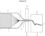
- FIGS. 1 and 2 are diagrams illustrating a manufacturing device of a secondary battery according to the related art by way of example.
- FIG .1 is a view illustrating a state before bending of an electrode lead in a manufacturing device of a secondary battery according to the related art
- FIG. 2 is a view illustrating a state after bending an electrode lead in a manufacturing device of a secondary battery according to the related art.
- an electrode assembly 1 is formed by stacking a plurality of positive electrodes and negative electrodes with a separator interposed therebetween, and the electrode assembly 1 may be accommodated in a battery case 2 to manufacture a secondary battery. Electrode tabs 3 connected to the respective electrodes included in the electrode assembly 1 may be collected and welded to be connected to an electrode lead 4 as shown in the drawing. A lead film 5 surrounding the electrode lead 4 may be located on the electrode lead 4 to increase sealing force with the battery case 2.
- the electrode lead 4 may be electrically connected to an external device, and may be appropriately molded into various shapes depending on the environment of a connection state.
- a process of bending the electrode lead 4 into an appropriate shape is required.
- upper and lower molds 30 and 40 having the shape of the electrode lead 4 to be obtained are prepared, a joint portion of the battery case 2 and the electrode lead 4 is fixed by an upper fixing mold 10 and a lower fixing mold 20, and in this state, the upper and lower molds 30 and 40 are combined to press the electrode lead 4.
- a strong tensile force is applied to a joint portion A of the electrode lead 4 and the electrode tab 3 by force that presses the electrode lead 4, and accordingly, the joint portion A of the electrode tab 3 and the electrode lead 4 may be disconnected.
- the problem to be solved by the present invention is a manufacturing device of a secondary battery and a manufacturing method of a secondary battery capable of preventing the occurrence of disconnection in a joint portion between an electrode tab and an electrode lead due to tensile force occurring in a molding process of the electrode lead.
- a manufacturing device of a secondary battery including a plurality of electrodes and separators which are alternately stacked, electrode tabs provided at end portions of the plurality of electrodes, and an electrode lead coupled to the electrode tabs, includes: an upper fixing mold and a lower fixing mold fixing the electrode lead with the electrode lead interposed therebetween; and a lower molding mold disposed to be spaced apart from the lower fixing mold toward an outer end portion of the electrode lead, and a plurality of upper molding molds disposed to be spaced apart from the upper fixing mold toward an end portion of the electrode lead, wherein the plurality of upper molding molds include a first upper molding mold for fixing the electrode leads and a second upper molding mold for forming first and second bent portions, and the first upper molding mold and the second upper molding mold are separated from each other and are sequentially disposed in a direction from the electrode assembly toward the end portion of the electrode lead.
- the first upper molding mold and the second upper molding mold may be movable independently of each other.
- the manufacturing device may further include: a third upper molding mold disposed to be adjacent to the second upper molding mold in a direction from the electrode assembly toward the end portion of the electrode lead and forming a third bent portion.
- the third upper molding mold may be separated from the first upper molding mold and the second upper molding mold and may be independently movable.
- Only the electrode lead may be disposed between the first upper molding mold and the lower molding mold.
- a manufacturing method of a secondary battery including a plurality of electrodes and separators which are alternately stacked, electrode tabs provided at end portions of the plurality of electrodes, and an electrode lead coupled to the electrode tabs includes: primarily fixing the electrode lead in a first fixing portion between an upper fixing mold and a lower fixing mold; secondarily fixing the electrode lead by lowering the first upper molding mold toward the lower molding mold in a second fixing portion spaced apart from the first fixing portion toward an outer end of the electrode lead, and forming first and second bent portions in the electrode lead by lowering, toward the lower molding mold, the second upper molding mold located to be adjacent to the first upper molding mold at an outer end portion side of the electrode lead.
- the manufacturing method may further include: forming a third bend portion in the electrode lead by lowering, toward the lower molding mold, a third upper molding mold located at an outer end portion side of the electrode lead with respect to the second upper molding mold in a state in which the second upper molding mold is lowered.
- only the electrode lead may be disposed between the first upper molding mold and the lower fixing mold.
- the electrode lead, a lead film surrounding the electrode lead, and a battery case of the secondary battery may be arranged between the upper fixing mold and the lower fixing mold.
- Force pressing the electrode lead by the first upper molding mold in the second fixing portion may be greater than force pressing the electrode lead by the upper fixing mold in the first fixing portion.
- in plan view it means that a target element is viewed from above, and when it is referred to "in cross-sectional view”, it means that a target element taken vertically is viewed from the side.
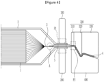
- FIGS. 3 and 4 a manufacturing device of a secondary battery according to an exemplary embodiment of the present invention will be described with reference to FIGS. 3 and 4 .
- the secondary battery includes an electrode assembly 1 accommodated in a battery case 2 and an electrode lead 4 drawn out of the battery case 2 for electrical connection with the outside.
- the electrode assembly 1 is a power generating device capable of charging and discharging and has a structure in which a negative electrode and a positive electrode are alternately stacked with a separator interposed therebetween.
- Electrode tabs 3 are formed by extending from end portions of the electrodes included in the electrode assembly 1, respectively. The electrode tabs 3 may be collected to be welded together at one point, and the collected electrode tabs 3 and the electrode lead 4 may be joined by a method, such as welding.
- One end of the electrode lead 4 may be electrically connected to the electrode tab 3, extends via a sealing portion of the battery case 2, and the opposite end protrudes outwardly from the battery case 2.
- a lead film 5 may be located to surround the electrode lead 4 in at least one of an upper portion and a lower portion of the electrode lead 4. The lead film 5 may improve sealing properties between the sealing portion of the battery case 2 and the electrode lead 4, while preventing a short circuit from occurring in the electrode lead 4 during thermal fusion.
- the manufacturing device of a secondary battery is a device for molding a portion protruding outwardly of the battery case 2 in the electrode lead 4 described above and includes an upper fixing mold 100 and a lower fixing mold 200 for fixing the electrode lead 4 and a plurality of upper molding molds 300 and a lower molding mold 400 for molding a shape of the electrode lead 4 directly in contact with the electrode lead 4.
- the upper fixing mold 100 and the lower fixing mold 200 are for fixing the electrode lead 4 during a molding process, and in particular, support a portion in which the electrode lead 4 is fixed to the battery case 2 to fix the electrode lead 4.
- the upper fixing mold 100 and the lower fixing mold 200 are formed to contact and press a portion in which the battery case 2 and the electrode lead 4 overlap each other, that is, a first fixing portion P1 vertically.
- the lead film 5 covering the electrode lead and the battery case 2 thermally fused to the lead film 5 may also be interposed and fixed together with the electrode lead 4 between the upper fixing mold 100 and the lower fixing mold 200.
- the lower molding mold 400 is spaced apart toward an outer end portion of the electrode lead 4 and disposed to be adjacent to the lower fixing mold 200.
- the lower molding mold 400 is in direct contact with the electrode lead 4 and is coupled to the upper molding mold 300 with the electrode lead 4 interposed therebetween, and a molding surface in contact with the electrode lead 4 has a shape corresponding to a shape of the electrode lead 4 to be molded.
- a case of having three curved surfaces is taken as an example, but is not limited thereto, and may be variously modified according to a final shape of the electrode lead 4 to be obtained.
- the upper molding mold 300 is spaced apart from the upper fixing mold 100 toward the outer end portion of the electrode lead 4.
- a plurality of upper molding molds 300 may be provided, and in the present exemplary embodiment, an example including three upper molding molds 300 is described, but the present invention is not limited thereto, and the number and position of the upper molding molds 300 may be variously adjusted.
- the upper molding mold 300 includes a first upper molding mold 310, a second upper molding mold 320 and a third upper molding mold 330. These first upper molding mold 310, second upper molding mold 320 and third upper molding mold 330 are sequentially arranged in a direction from the upper fixing mold 100 toward the outer end portion of the electrode lead 4. A molding surface facing the lower molding mold 400 in a state in which the three upper molding molds 300 are combined has a shape corresponding to a shape of the electrode lead 4 to be molded.
- the first upper molding mold 310, the second upper molding mold 320, and the third upper molding mold 330 are formed separately from each other, and thus may be independently controlled during a process. For example, the first upper molding mold 310, the second upper molding mold 320, and the third upper molding mold 330 may be sequentially lowered one by one and controlled to be coupled to the lower molding mold 400, while pressing the electrode lead 4.
- the first upper molding mold 310 may press the electrode lead 4 with the electrode lead 4 interposed between the first upper molding mold 310 and the lower molding mold 400 in a second fixing portion P2.
- the second fixing portion P2 is spaced apart from the first fixing portion P1 in a direction toward the outer end of the electrode lead 4. In a portion in which the second fixing portion P2 is located, only the electrode lead 4 extends, and the lead film 5 and the battery case 2 are not located. Therefore, in the second fixing portion P2, fixing may be performed in a state in which only the electrode lead 4 is disposed between the lower molding mold 400 and the first upper molding mold 310, and fixing may be performed by more reliably pressing the electrode lead 4 than in the first fixing portion P1.
- a length of the electrode lead 4 fixed at the second fixing portion P2 may be increased by increasing a width of the second fixing portion P2 within a range in which interference between molds does not occur, and accordingly, the electrode lead 4 may be fixed with stronger force.
- the second upper molding mold 320 is spaced apart from the first upper molding mold 310 in a direction toward the outer end portion of the electrode lead 4.
- a molding surface of the second upper molding mold 320 has a continuous shape from the first upper molding mold 310 and has a shape corresponding to first and second bent portions 41 and 42 (shown in FIG. 6 ), but, without being limited thereto, the molding surface of the second upper molding mold 320 may have various shapes according to the shape of the electrode lead 4.
- the third upper molding mold 330 is separated from the second upper molding mold 320 in the direction toward the outer end portion of the electrode lead 4.
- a molding surface of the third upper molding mold 330 may have a continuous shape from the second upper molding mold 320 and may have a shape corresponding to a third bent portion 43 (shown in FIG. 6 ), but without being limited thereto, the molding surface of the third upper molding mold 330 may have various shapes according to the shape of the electrode lead 4.
- the first to third upper molding molds 310, 320, and 330 may be separated from each other and sequentially lowered to be coupled with the lower molding mold 400 to mold the electrode lead 4. According to this configuration, since additional fixing is performed in the second fixing portion P2 by the first upper molding mold 310, the magnitude of tensile force applied to the electrode lead 4 during molding of the electrode lead 4 may be reduced. That is, tensile force applied to the electrode lead 4, in particular, a joint portion A between the electrode lead 4 and the electrode tab 3, is generated as much as a direction in which the electrode lead 4 is pulled during molding, but may be reduced by frictional force generated by fixing in the first and second fixing portions P1 and P2.
- disconnection may be prevented by minimizing tensile force applied to the electrode lead 4 and the electrode tab 3 during bending of the electrode lead 4.
- FIGS. 5 to 7 are views illustrating a manufacturing method of a secondary battery according to an exemplary embodiment of the present invention.
- pressure may be applied to the first fixing portion P1 and the second fixing portion P2 by the upper fixing mold 100 or the first upper molding mold 310 for additional fixing.
- the electrode lead 4 may be fixed more reliably.
- force applied in the first fixing portion P1 and the second fixing portion P2 may be the same, or a greater force may be applied in the second fixing portion P2.
- the second fixing portion P2 only the electrode lead 4 is fixed, and since the electrode lead 4 has greater strength than that of the battery case 2 or the like fixed in the first fixing portion P1, a possibility of the occurrence of a dent and damage against greater pressure may be reduced. Therefore, when it is necessary to increase fixing strength, it is preferable to increase fixing strength by increasing pressing force in the second fixing portion P2.
- the second upper molding mold 320 disposed to be adjacent to the first upper molding mold 310 are lowered toward the lower molding mold 400 to form the first bent portion 41 and the second bent portion 42. That is, the first bent portion 41 may be formed in a portion in which the first upper molding mold 310 and the second upper molding mold 320 are continuous, and may be bent as the second upper molding mold 320 is lowered, while pressing the electrode lead 4.
- the second bent portion 42 may be formed to be bent along the shape of the molding surface of the second upper molding mold 320.
- molding of the electrode lead 4 may be completed by lowering the third upper molding mold 330 to form the third bent portion 43.
- the manufacturing method of molding the electrode lead 4 using the manufacturing device of a secondary battery since the electrode lead 4 is fixed by the first and second fixing portions P, while the electrode lead 4 is pressed and a tensile force is applied, tensile force applied to the electrode lead 4 may be reduced.
- tensile force is sequentially applied in order close to the electrode assembly, rather than that the molding mold across the entire region of the electrode lead 4 applies tensile force at once, the tensile force applied to the electrode lead 4 may be distributed over time, thereby preventing disconnection that may occur when excessive tensile force is applied to the electrode lead 4.
- molding is performed by dividing the upper molding mold 300 into three stages, but the upper molding mold 300 may be divided in various ways according to the shape of the electrode lead 4 and a process situation to perform molding.
- Example 1 the first to third upper molding molds 310, 320, and 330 were sequentially moved by about 12 mm in the manufacturing method of FIGS. 5 to 7 , and at this time, in the first fixing portion P1, pressure was applied with force of 45 kgf, and in the second fixing portion P2, only the first upper molding mold 310, the second upper molding mold 320, and the third upper molding mold 330 perform molding sequentially without fixing.
- Example 2 molding was performed in the same manner as in Example 1, but fixing was additionally performed also in the second fixing portion P2 by applying pressure with force of 45 kgf.
- Example 3 molding was performed in the same manner as in Example 2, but the widths of the first upper molding mold 310 and the lower molding mold 400 were increased by 2.5 mm toward the fixing molds 100 and 200 and fixing was performed in a state in which the length by which the electrode lead 4 and the mold contact each other is increased in the second fixing portion P2.
- the contact area between the electrode lead 4 and the mold in the second fixing portion P2 increased 3 times compared to Example 2, and as a result, fixing was performed in the second fixing portion P2 by applying pressure with force of 135 kgf increased three times.
- the electrode lead 4 was molded by moving an upper mold 30 by about 12 mm in the same manner as in Example 1 using the mold of FIGS. 1 and 2 .
Landscapes
- Chemical & Material Sciences (AREA)
- Chemical Kinetics & Catalysis (AREA)
- Electrochemistry (AREA)
- General Chemical & Material Sciences (AREA)
- Engineering & Computer Science (AREA)
- Manufacturing & Machinery (AREA)
- Mechanical Engineering (AREA)
- Secondary Cells (AREA)
- Connection Of Batteries Or Terminals (AREA)
Abstract
Description
- This application claims priority to and the benefit of
Korean Patent Application No. 10-2022-0088171 filed in the Korean Intellectual Property Office on July 18, 2022 - The present invention relates to a manufacturing device of a secondary battery and a manufacturing method of a secondary battery, and specifically, to a manufacturing device of a secondary battery and a manufacturing method of a secondary battery capable of preventing disconnection by reducing tensile stress applied to a joint portion between an electrode lead and an electrode tab.
- Due to the rapid increase in the use of fossil fuels, demand for the use of alternative energy and clean energy has increased, and as part thereof, the most actively researched areas are power generation and storage using electrochemistry.
- Currently, secondary batteries may be a representative example of electrochemical devices using such electrochemical energy, and a use range thereof has gradually expanded.
- Recently, as the technology development and demand for portable devices, such as portable computers, mobile phones, and cameras have increased, demand for secondary batteries as an energy source has rapidly increased. Among them, many studies have been conducted on lithium secondary batteries that exhibit high energy density and operating potential, have long cycle life and low self-discharge rate, lithium secondary batteries have also been commercialized and widely used.
- In addition, as interest in environmental issues has grown, research on electric vehicles and hybrid electric vehicles that may replace vehicles using fossil fuels, such as gasoline vehicles and diesel vehicles, which are one of the main causes of air pollution, has been conducted. Nickel metal hydride secondary batteries have mainly been used as a power source for electric vehicles and hybrid electric vehicles, but research using lithium secondary batteries with high energy density and discharge voltage have been actively conducted, and some lithium secondary batteries have reached commercialization.
- Such a lithium secondary battery is manufactured by coating a positive electrode or a negative electrode active material, a binder, and a conductive material in the form of slurry on a current collector and drying the same to form an electrode mixture layer to manufacture a positive electrode and a negative electrode, interposing a separator between the positive electrode and the negative electrode, and embedding an electrode assembly obtained by laminating the positive electrode, the negative electrode, and the separator in a battery case together with the electrolyte. Electrode tabs extending from each cell of the electrode assembly embedded in the battery case are welded together and welded to be connected to electrode leads. The lithium secondary battery may be electrically connected to an external device by the electrode leads.
-
FIGS. 1 and2 are diagrams illustrating a manufacturing device of a secondary battery according to the related art by way of example. -
FIG .1 is a view illustrating a state before bending of an electrode lead in a manufacturing device of a secondary battery according to the related art, andFIG. 2 is a view illustrating a state after bending an electrode lead in a manufacturing device of a secondary battery according to the related art. - Referring to
FIGS. 1 and2 , anelectrode assembly 1 is formed by stacking a plurality of positive electrodes and negative electrodes with a separator interposed therebetween, and theelectrode assembly 1 may be accommodated in abattery case 2 to manufacture a secondary battery.Electrode tabs 3 connected to the respective electrodes included in theelectrode assembly 1 may be collected and welded to be connected to anelectrode lead 4 as shown in the drawing. Alead film 5 surrounding theelectrode lead 4 may be located on theelectrode lead 4 to increase sealing force with thebattery case 2. - The
electrode lead 4 may be electrically connected to an external device, and may be appropriately molded into various shapes depending on the environment of a connection state. In order to form theelectrode lead 4, a process of bending theelectrode lead 4 into an appropriate shape is required. For such bending, as shown inFIGS. 1 and2 , upper andlower molds electrode lead 4 to be obtained are prepared, a joint portion of thebattery case 2 and theelectrode lead 4 is fixed by anupper fixing mold 10 and alower fixing mold 20, and in this state, the upper andlower molds electrode lead 4. At this time, in particular, a strong tensile force is applied to a joint portion A of theelectrode lead 4 and theelectrode tab 3 by force that presses theelectrode lead 4, and accordingly, the joint portion A of theelectrode tab 3 and theelectrode lead 4 may be disconnected. - The problem to be solved by the present invention is a manufacturing device of a secondary battery and a manufacturing method of a secondary battery capable of preventing the occurrence of disconnection in a joint portion between an electrode tab and an electrode lead due to tensile force occurring in a molding process of the electrode lead.
- However, the problems to be solved by the exemplary embodiments of the present invention are not limited to the above problems and may be variously extended within the scope of the technical idea included in the present invention.
- According to an exemplary embodiment of the present invention, a manufacturing device of a secondary battery, including a plurality of electrodes and separators which are alternately stacked, electrode tabs provided at end portions of the plurality of electrodes, and an electrode lead coupled to the electrode tabs, includes: an upper fixing mold and a lower fixing mold fixing the electrode lead with the electrode lead interposed therebetween; and a lower molding mold disposed to be spaced apart from the lower fixing mold toward an outer end portion of the electrode lead, and a plurality of upper molding molds disposed to be spaced apart from the upper fixing mold toward an end portion of the electrode lead, wherein the plurality of upper molding molds include a first upper molding mold for fixing the electrode leads and a second upper molding mold for forming first and second bent portions, and the first upper molding mold and the second upper molding mold are separated from each other and are sequentially disposed in a direction from the electrode assembly toward the end portion of the electrode lead.
- The first upper molding mold and the second upper molding mold may be movable independently of each other.
- The manufacturing device may further include: a third upper molding mold disposed to be adjacent to the second upper molding mold in a direction from the electrode assembly toward the end portion of the electrode lead and forming a third bent portion.
- The third upper molding mold may be separated from the first upper molding mold and the second upper molding mold and may be independently movable.
- Only the electrode lead may be disposed between the first upper molding mold and the lower molding mold.
- According to another exemplary embodiment of the present invention, a manufacturing method of a secondary battery including a plurality of electrodes and separators which are alternately stacked, electrode tabs provided at end portions of the plurality of electrodes, and an electrode lead coupled to the electrode tabs, includes: primarily fixing the electrode lead in a first fixing portion between an upper fixing mold and a lower fixing mold; secondarily fixing the electrode lead by lowering the first upper molding mold toward the lower molding mold in a second fixing portion spaced apart from the first fixing portion toward an outer end of the electrode lead, and forming first and second bent portions in the electrode lead by lowering, toward the lower molding mold, the second upper molding mold located to be adjacent to the first upper molding mold at an outer end portion side of the electrode lead.
- The manufacturing method may further include: forming a third bend portion in the electrode lead by lowering, toward the lower molding mold, a third upper molding mold located at an outer end portion side of the electrode lead with respect to the second upper molding mold in a state in which the second upper molding mold is lowered.
- In the second fixing portion, only the electrode lead may be disposed between the first upper molding mold and the lower fixing mold.
- In the first fixing portion, the electrode lead, a lead film surrounding the electrode lead, and a battery case of the secondary battery may be arranged between the upper fixing mold and the lower fixing mold.
- In the first fixing portion and the second fixing portion, the same magnitude of force may be applied to the upper fixing mold and the first upper molding mold to press the electrode lead.
- Force pressing the electrode lead by the first upper molding mold in the second fixing portion may be greater than force pressing the electrode lead by the upper fixing mold in the first fixing portion.
- According to exemplary embodiments of the present invention, it is possible to prevent disconnection in the joint portion between the electrode tab and the electrode lead by minimizing the occurrence of tensile force in the molding process of the electrode lead.
- The effects of the present invention are not limited to the effects mentioned above, and other effects not mentioned will be clearly understood by those skilled in the art from the description of the claims.
-
-
FIG. 1 is a view illustrating a state before bending an electrode lead in a manufacturing device of a secondary battery according to the related art. -
FIG. 2 is a view illustrating a state after bending an electrode lead in a manufacturing device of a secondary battery according to the related art. -
FIG. 3 is a view illustrating a state before bending an electrode lead in a manufacturing device of a secondary battery according to an exemplary embodiment of the present invention. -
FIG. 4 is a view illustrating a state after bending an electrode lead in the manufacturing device of a secondary battery ofFIG. 3 . -
FIGS. 5 to 7 are views illustrating a manufacturing method of a secondary battery according to an exemplary embodiment of the present invention. - Hereinafter, exemplary embodiments of the present invention will be described in detail with reference to the accompanying drawings to allow those skilled in the art to practice the present invention. The present invention may be implemented in various different forms and is not limited to the examples as described herein.
- In order to clearly describe the present invention, parts unrelated to the description will be omitted. Throughout the specification, the same or similar constituent elements are marked with the same reference number.
- The size and thickness of each component shown in the drawings may be arbitrarily shown for convenience of explanation, and therefore, the present invention is not necessarily limited to the shown exemplary embodiments in the drawings. In the drawings, the thickness of layers, films, panels, regions, etc., are exaggerated for clarity. Also, in the drawings, the thickness of partial layers and regions may be exaggerated for convenience of explanation.
- It will be understood that when an element, such as a layer, film, region, or substrate is referred to as being "on" another element, it may be directly on the other element or intervening elements may also be present. In contrast, when an element is referred to as being "directly on" another element, there are no intervening elements present. Further, when an element is "above" or "on" the reference portion, it may mean that the element is located above or below the reference portion, and it may not necessarily mean that the element is "above" or "on" toward an opposite direction of gravity.
- In addition, unless explicitly described to the contrary, the word "comprise", and variations, such as "comprises" or "comprising", will be understood to imply the inclusion of stated elements but not the exclusion of any other elements.
- Throughout the specification, when it is referred to "in plan view", it means that a target element is viewed from above, and when it is referred to "in cross-sectional view", it means that a target element taken vertically is viewed from the side.
- Hereinafter, a manufacturing device of a secondary battery according to an exemplary embodiment of the present invention will be described with reference to
FIGS. 3 and4 . - The secondary battery includes an
electrode assembly 1 accommodated in abattery case 2 and anelectrode lead 4 drawn out of thebattery case 2 for electrical connection with the outside. Theelectrode assembly 1 is a power generating device capable of charging and discharging and has a structure in which a negative electrode and a positive electrode are alternately stacked with a separator interposed therebetween.Electrode tabs 3 are formed by extending from end portions of the electrodes included in theelectrode assembly 1, respectively. Theelectrode tabs 3 may be collected to be welded together at one point, and the collectedelectrode tabs 3 and theelectrode lead 4 may be joined by a method, such as welding. - One end of the
electrode lead 4 may be electrically connected to theelectrode tab 3, extends via a sealing portion of thebattery case 2, and the opposite end protrudes outwardly from thebattery case 2. Alead film 5 may be located to surround theelectrode lead 4 in at least one of an upper portion and a lower portion of theelectrode lead 4. Thelead film 5 may improve sealing properties between the sealing portion of thebattery case 2 and theelectrode lead 4, while preventing a short circuit from occurring in theelectrode lead 4 during thermal fusion. - Referring to
FIGS. 3 and4 , the manufacturing device of a secondary battery according to an exemplary embodiment of the present invention is a device for molding a portion protruding outwardly of thebattery case 2 in theelectrode lead 4 described above and includes anupper fixing mold 100 and alower fixing mold 200 for fixing theelectrode lead 4 and a plurality ofupper molding molds 300 and alower molding mold 400 for molding a shape of theelectrode lead 4 directly in contact with theelectrode lead 4. - The
upper fixing mold 100 and thelower fixing mold 200 are for fixing theelectrode lead 4 during a molding process, and in particular, support a portion in which theelectrode lead 4 is fixed to thebattery case 2 to fix theelectrode lead 4. To this end, as shown inFIGS. 3 and4 , the upper fixingmold 100 and thelower fixing mold 200 are formed to contact and press a portion in which thebattery case 2 and theelectrode lead 4 overlap each other, that is, a first fixing portion P1 vertically. In the first fixing portion P1, thelead film 5 covering the electrode lead and thebattery case 2 thermally fused to thelead film 5 may also be interposed and fixed together with theelectrode lead 4 between the upper fixingmold 100 and thelower fixing mold 200. - The
lower molding mold 400 is spaced apart toward an outer end portion of theelectrode lead 4 and disposed to be adjacent to thelower fixing mold 200. Thelower molding mold 400 is in direct contact with theelectrode lead 4 and is coupled to theupper molding mold 300 with theelectrode lead 4 interposed therebetween, and a molding surface in contact with theelectrode lead 4 has a shape corresponding to a shape of theelectrode lead 4 to be molded. In the present exemplary embodiment, a case of having three curved surfaces is taken as an example, but is not limited thereto, and may be variously modified according to a final shape of theelectrode lead 4 to be obtained. - The
upper molding mold 300 is spaced apart from the upper fixingmold 100 toward the outer end portion of theelectrode lead 4. A plurality ofupper molding molds 300 may be provided, and in the present exemplary embodiment, an example including threeupper molding molds 300 is described, but the present invention is not limited thereto, and the number and position of theupper molding molds 300 may be variously adjusted. - Referring to
FIGS. 3 and4 , in the present exemplary embodiment, theupper molding mold 300 includes a firstupper molding mold 310, a secondupper molding mold 320 and a thirdupper molding mold 330. These firstupper molding mold 310, secondupper molding mold 320 and thirdupper molding mold 330 are sequentially arranged in a direction from the upper fixingmold 100 toward the outer end portion of theelectrode lead 4. A molding surface facing thelower molding mold 400 in a state in which the threeupper molding molds 300 are combined has a shape corresponding to a shape of theelectrode lead 4 to be molded. In addition, the firstupper molding mold 310, the secondupper molding mold 320, and the thirdupper molding mold 330 are formed separately from each other, and thus may be independently controlled during a process. For example, the firstupper molding mold 310, the secondupper molding mold 320, and the thirdupper molding mold 330 may be sequentially lowered one by one and controlled to be coupled to thelower molding mold 400, while pressing theelectrode lead 4. - At this time, the first
upper molding mold 310 may press theelectrode lead 4 with theelectrode lead 4 interposed between the firstupper molding mold 310 and thelower molding mold 400 in a second fixing portion P2. The second fixing portion P2 is spaced apart from the first fixing portion P1 in a direction toward the outer end of theelectrode lead 4. In a portion in which the second fixing portion P2 is located, only theelectrode lead 4 extends, and thelead film 5 and thebattery case 2 are not located. Therefore, in the second fixing portion P2, fixing may be performed in a state in which only theelectrode lead 4 is disposed between thelower molding mold 400 and the firstupper molding mold 310, and fixing may be performed by more reliably pressing theelectrode lead 4 than in the first fixing portion P1. In addition, in some cases, a length of theelectrode lead 4 fixed at the second fixing portion P2 may be increased by increasing a width of the second fixing portion P2 within a range in which interference between molds does not occur, and accordingly, theelectrode lead 4 may be fixed with stronger force. - The second
upper molding mold 320 is spaced apart from the firstupper molding mold 310 in a direction toward the outer end portion of theelectrode lead 4. A molding surface of the secondupper molding mold 320 has a continuous shape from the firstupper molding mold 310 and has a shape corresponding to first and second bent portions 41 and 42 (shown inFIG. 6 ), but, without being limited thereto, the molding surface of the secondupper molding mold 320 may have various shapes according to the shape of theelectrode lead 4. - The third
upper molding mold 330 is separated from the secondupper molding mold 320 in the direction toward the outer end portion of theelectrode lead 4. A molding surface of the thirdupper molding mold 330 may have a continuous shape from the secondupper molding mold 320 and may have a shape corresponding to a third bent portion 43 (shown inFIG. 6 ), but without being limited thereto, the molding surface of the thirdupper molding mold 330 may have various shapes according to the shape of theelectrode lead 4. - The first to third
upper molding molds lower molding mold 400 to mold theelectrode lead 4. According to this configuration, since additional fixing is performed in the second fixing portion P2 by the firstupper molding mold 310, the magnitude of tensile force applied to theelectrode lead 4 during molding of theelectrode lead 4 may be reduced. That is, tensile force applied to theelectrode lead 4, in particular, a joint portion A between theelectrode lead 4 and theelectrode tab 3, is generated as much as a direction in which theelectrode lead 4 is pulled during molding, but may be reduced by frictional force generated by fixing in the first and second fixing portions P1 and P2. In the related art, fixing is performed only in the first fixing portion P1, and since theelectrode lead 4 is fixed in the corresponding portion via thelead film 5 and thebattery case 2, frictional force generated by the fixing is not enough to reduce the magnitude of tensile force generated during molding and transmitted to the joint portion A between theelectrode lead 4 and theelectrode tab 3 as it is, causing problems, such as disconnection. However, in the present exemplary embodiment, since additional fixing is performed in the second fixing portion P2 and only theelectrode lead 4 is directly fixed in the corresponding portion, the magnitude of the frictional force may be further increased, and thus, the magnitude of tensile force generated during molding may be sufficiently reduced, and thus, the occurrence of disconnection in the joint portion A between theelectrode lead 4 and theelectrode tab 3 may be prevented. - In addition, compared to a case in which the molding mold presses the
electrode lead 4 at once, the molding mold is divided and sequentially lowered to press theelectrode lead 4, and thus, since the magnitude of the tensile force generated at once is reduced, thereby efficiently preventing disconnection of theelectrode lead 4. As described above, according to the manufacturing device of a secondary battery according to an exemplary embodiment of the present invention, disconnection may be prevented by minimizing tensile force applied to theelectrode lead 4 and theelectrode tab 3 during bending of theelectrode lead 4. - Hereinafter, as a manufacturing method using the manufacturing device of a secondary battery described above, a manufacturing method of a secondary battery according to one exemplary embodiment and another exemplary embodiment of the present invention will be described.
-
FIGS. 5 to 7 are views illustrating a manufacturing method of a secondary battery according to an exemplary embodiment of the present invention. - Referring to
FIG. 5 , in the manufacturing method of a secondary battery according to an exemplary embodiment of the present invention, first, theelectrode lead 4 is fixed between (the first fixing portion P1) the upper fixingmold 100 and thelower fixing mold 200. Thereafter, the firstupper molding mold 310 is lowered toward thelower molding mold 400. At this time, theelectrode lead 4 may be additionally fixed in the second fixing portion P2, or theupper molding mold 300 may be sequentially lowered to be applied without additional fixing. In the case of additional fixing, not only theelectrode lead 4 but also thelead film 5 and a portion of thebattery case 2 may be fixed together to the first fixing portion P1, and only theelectrode lead 4 may be fixed to the second fixing portion P2. - In addition, pressure may be applied to the first fixing portion P1 and the second fixing portion P2 by the upper fixing
mold 100 or the firstupper molding mold 310 for additional fixing. Thereby, theelectrode lead 4 may be fixed more reliably. At this time, force applied in the first fixing portion P1 and the second fixing portion P2 may be the same, or a greater force may be applied in the second fixing portion P2. In the second fixing portion P2, only theelectrode lead 4 is fixed, and since theelectrode lead 4 has greater strength than that of thebattery case 2 or the like fixed in the first fixing portion P1, a possibility of the occurrence of a dent and damage against greater pressure may be reduced. Therefore, when it is necessary to increase fixing strength, it is preferable to increase fixing strength by increasing pressing force in the second fixing portion P2. - Next, referring to
FIG. 6 , the secondupper molding mold 320 disposed to be adjacent to the firstupper molding mold 310 are lowered toward thelower molding mold 400 to form the first bent portion 41 and the second bent portion 42. That is, the first bent portion 41 may be formed in a portion in which the firstupper molding mold 310 and the secondupper molding mold 320 are continuous, and may be bent as the secondupper molding mold 320 is lowered, while pressing theelectrode lead 4. The second bent portion 42 may be formed to be bent along the shape of the molding surface of the secondupper molding mold 320. - Lastly, referring to
FIG. 7 , molding of theelectrode lead 4 may be completed by lowering the thirdupper molding mold 330 to form the thirdbent portion 43. - As described above, in the manufacturing method of molding the
electrode lead 4 using the manufacturing device of a secondary battery according to an exemplary embodiment of the present invention, since theelectrode lead 4 is fixed by the first and second fixing portions P, while theelectrode lead 4 is pressed and a tensile force is applied, tensile force applied to theelectrode lead 4 may be reduced. In addition, since tensile force is sequentially applied in order close to the electrode assembly, rather than that the molding mold across the entire region of theelectrode lead 4 applies tensile force at once, the tensile force applied to theelectrode lead 4 may be distributed over time, thereby preventing disconnection that may occur when excessive tensile force is applied to theelectrode lead 4. In addition, in the present exemplary embodiment, molding is performed by dividing theupper molding mold 300 into three stages, but theupper molding mold 300 may be divided in various ways according to the shape of theelectrode lead 4 and a process situation to perform molding. - Hereinafter, tensile force generated in the manufacturing method of a secondary battery according to exemplary embodiments of the present invention and a manufacturing method of a secondary battery according to Comparative Example will be measured and results thereof will be described.
- In Example 1, the first to third
upper molding molds FIGS. 5 to 7 , and at this time, in the first fixing portion P1, pressure was applied with force of 45 kgf, and in the second fixing portion P2, only the firstupper molding mold 310, the secondupper molding mold 320, and the thirdupper molding mold 330 perform molding sequentially without fixing. - In Example 2, molding was performed in the same manner as in Example 1, but fixing was additionally performed also in the second fixing portion P2 by applying pressure with force of 45 kgf.
- In Example 3, molding was performed in the same manner as in Example 2, but the widths of the first
upper molding mold 310 and thelower molding mold 400 were increased by 2.5 mm toward the fixingmolds electrode lead 4 and the mold contact each other is increased in the second fixing portion P2. As a result, the contact area between theelectrode lead 4 and the mold in the second fixing portion P2 increased 3 times compared to Example 2, and as a result, fixing was performed in the second fixing portion P2 by applying pressure with force of 135 kgf increased three times. - Meanwhile, in Comparative Example, the
electrode lead 4 was molded by moving anupper mold 30 by about 12 mm in the same manner as in Example 1 using the mold ofFIGS. 1 and2 . - During molding in Examples 1 to 3 and Comparative Example, the maximum values of tensile force applied to the joint portion A between the
electrode tab 3 and theelectrode lead 4 were measured. The results are shown in Table 1 below.[Table 1] Maximum tensile force(N) Rate of change of maximum tensile force compared to Comparative Example (%) Comparative Example 665.4 - Example 1 439.9 -33.9 Example 2 332.0 -50.1 Example 3 172.5 -74.1 - As shown in Table 1, in the case of Examples of the present invention, it was confirmed that the maximum tensile force values were significantly lower than that of Comparative Example. Accordingly, it can be seen that disconnection of the
electrode tab 3 and theelectrode lead 4 may be prevented from occurring in the molding process of theelectrode lead 4 according to the exemplary embodiments of the present invention. - The exemplary embodiments of the present invention have been described in detail, but the scope of the present invention is not limited thereto and various variants and modifications by a person skilled in the art using a basic concept of the present invention defined in claims also belong to the scope of the present invention.
-
- 3: electrode tab
- 4: electrode lead
- 100: upper fixing mold
- 200: lower fixing mold
- 300: upper molding mold
- 310: first upper molding mold
- 320: second upper molding mold
- 330: third upper molding mold
- 400: lower molding mold
Claims (11)
- A manufacturing device of a secondary battery including a plurality of electrodes and separators which are alternately stacked, electrode tabs provided at end portions of the plurality of electrodes, and an electrode lead coupled to the electrode tabs, the manufacturing device comprising:an upper fixing mold and a lower fixing mold fixing the electrode lead with the electrode lead interposed therebetween; anda lower molding mold disposed to be spaced apart from the lower fixing mold toward an outer end portion of the electrode lead, and a plurality of upper molding molds disposed to be spaced apart from the upper fixing mold toward an end portion of the electrode lead,wherein the plurality of upper molding molds include a first upper molding mold for fixing the electrode leads and a second upper molding mold for forming first and second bent portions, andthe first upper molding mold and the second upper molding mold are separated from each other and are sequentially disposed in a direction from the electrode assembly toward the end portion of the electrode lead.
- The manufacturing device of claim 1, wherein:
the first upper molding mold and the second upper molding mold are movable independently of each other. - The manufacturing device of claim 1, further comprising:
a third upper molding mold disposed to be adjacent to the second upper molding mold in a direction from the electrode assembly toward the end portion of the electrode lead and forming a third bent portion. - The manufacturing device of claim 3, wherein:
the third upper molding mold is separated from the first upper molding mold and the second upper molding mold and is independently movable. - The manufacturing device of claim 1, wherein:
only the electrode lead is disposed between the first upper molding mold and the lower molding mold. - A manufacturing method of a secondary battery including a plurality of electrodes and separators which are alternately stacked, electrode tabs provided at end portions of the plurality of electrodes, and an electrode lead coupled to the electrode tabs, the manufacturing method comprising:primarily fixing the electrode lead in a first fixing portion between an upper fixing mold and a lower fixing mold;secondarily fixing the electrode lead by lowering the first upper molding mold toward the lower molding mold in a second fixing portion spaced apart from the first fixing portion toward an outer end of the electrode lead, andforming first and second bent portions in the electrode lead by lowering, toward the lower molding mold, the second upper molding mold located to be adjacent to the first upper molding mold at an outer end portion side of the electrode lead.
- The manufacturing method of claim 6, further comprising:
forming a third bend portion in the electrode lead by lowering, toward the lower molding mold, a third upper molding mold located at the outer end portion side of the electrode lead with respect to the second upper molding mold, in a state in which the second upper molding mold is lowered. - The manufacturing method of claim 6, wherein:
in the second fixing portion, only the electrode lead is disposed between the first upper molding mold and the lower fixing mold. - The manufacturing method of claim 8, wherein:
in the first fixing portion, the electrode lead, a lead film surrounding the electrode lead, and a battery case of the secondary battery are arranged between the upper fixing mold and the lower fixing mold. - The manufacturing method of claim 6, wherein:
in the first fixing portion and the second fixing portion, the same magnitude of force is applied to the upper fixing mold and the first upper molding mold to press the electrode lead. - The manufacturing method of claim 6, wherein:
force pressing the electrode lead by the first upper molding mold in the second fixing portion is greater than force pressing the electrode lead by the upper fixing mold in the first fixing portion.
Applications Claiming Priority (2)
| Application Number | Priority Date | Filing Date | Title |
|---|---|---|---|
| KR1020220088171A KR20240010880A (en) | 2022-07-18 | 2022-07-18 | Manufacturing device of secondary battery and manufacturing method of secondary battery |
| PCT/KR2023/010171 WO2024019445A1 (en) | 2022-07-18 | 2023-07-17 | Manufacturing device of secondary battery and manufacturing method of secondary battery |
Publications (2)
| Publication Number | Publication Date |
|---|---|
| EP4531200A1 true EP4531200A1 (en) | 2025-04-02 |
| EP4531200A4 EP4531200A4 (en) | 2025-10-22 |
Family
ID=89618114
Family Applications (1)
| Application Number | Title | Priority Date | Filing Date |
|---|---|---|---|
| EP23843294.2A Pending EP4531200A4 (en) | 2022-07-18 | 2023-07-17 | Apparatus for producing a secondary battery and method for producing a secondary battery |
Country Status (6)
| Country | Link |
|---|---|
| US (1) | US20260045650A1 (en) |
| EP (1) | EP4531200A4 (en) |
| JP (1) | JP2025523120A (en) |
| KR (1) | KR20240010880A (en) |
| CN (1) | CN119404371A (en) |
| WO (1) | WO2024019445A1 (en) |
Families Citing this family (1)
| Publication number | Priority date | Publication date | Assignee | Title |
|---|---|---|---|---|
| US12444814B2 (en) * | 2021-11-29 | 2025-10-14 | Lg Energy Solution, Ltd. | Apparatus for welding electrode tabs, method for welding electrode tabs, and secondary battery |
Family Cites Families (14)
| Publication number | Priority date | Publication date | Assignee | Title |
|---|---|---|---|---|
| JPS56119632A (en) * | 1980-02-27 | 1981-09-19 | Hitachi Ltd | Complex press working device |
| JPH0233447U (en) * | 1988-08-25 | 1990-03-02 | ||
| JP2904185B2 (en) * | 1997-05-06 | 1999-06-14 | サンケン電気株式会社 | Lead molding equipment for electronic parts |
| JP2000331669A (en) * | 1999-05-21 | 2000-11-30 | Sony Corp | Battery lead forming method and apparatus |
| JP2001160389A (en) * | 1999-12-01 | 2001-06-12 | Toshiba Battery Co Ltd | Lead bending device |
| JP2011218405A (en) * | 2010-04-09 | 2011-11-04 | Alps Electric Co Ltd | Manufacturing method of manufacturing dimple substrate by pressing, press device and the dimple substrate manufactured by the manufacturing method |
| WO2012118306A2 (en) * | 2011-02-28 | 2012-09-07 | Kang Tae In | Apparatus and method for manufacturing a battery terminal plate |
| KR101815335B1 (en) * | 2013-12-19 | 2018-01-04 | 주식회사 엘지화학 | A Forming Apparatus for a Pouch Having Slope Sidewall and a Forming Method thereby |
| KR101811835B1 (en) * | 2015-01-13 | 2018-01-25 | 주식회사 엘지화학 | Manufacture Device of Terrace for Battery Cell and Method for Terrace Design Structure Using the Same |
| JP6361929B2 (en) * | 2015-03-27 | 2018-07-25 | 株式会社デンソー | Stator coil forming device |
| KR102261492B1 (en) * | 2017-01-12 | 2021-06-07 | 주식회사 엘지에너지솔루션 | Pouch forming method of secondary battery |
| JP7374423B2 (en) * | 2019-01-31 | 2023-11-07 | 株式会社Aescジャパン | Electrode tab molding method and electrode tab molding device |
| CN209810973U (en) * | 2019-03-08 | 2019-12-20 | 广东利元亨智能装备股份有限公司 | a bending device |
| KR102751962B1 (en) * | 2020-01-15 | 2025-01-10 | 주식회사 엘지에너지솔루션 | The Apparatus And The Method For Folding Electrode Tab |
-
2022
- 2022-07-18 KR KR1020220088171A patent/KR20240010880A/en active Pending
-
2023
- 2023-07-17 US US18/995,459 patent/US20260045650A1/en active Pending
- 2023-07-17 WO PCT/KR2023/010171 patent/WO2024019445A1/en not_active Ceased
- 2023-07-17 EP EP23843294.2A patent/EP4531200A4/en active Pending
- 2023-07-17 JP JP2025501862A patent/JP2025523120A/en active Pending
- 2023-07-17 CN CN202380049237.6A patent/CN119404371A/en active Pending
Also Published As
| Publication number | Publication date |
|---|---|
| US20260045650A1 (en) | 2026-02-12 |
| JP2025523120A (en) | 2025-07-17 |
| CN119404371A (en) | 2025-02-07 |
| EP4531200A4 (en) | 2025-10-22 |
| KR20240010880A (en) | 2024-01-25 |
| WO2024019445A1 (en) | 2024-01-25 |
Similar Documents
| Publication | Publication Date | Title |
|---|---|---|
| US9548517B2 (en) | Battery cell of stair-like structure | |
| US11923564B2 (en) | Method for producing battery module | |
| US9478773B2 (en) | Battery cell of asymmetric structure and battery pack employed with the same | |
| US20110162198A1 (en) | Method of producing solid electrolyte-electrode assembly | |
| EP4057438A1 (en) | Electrode tab bending apparatus and method | |
| KR101934398B1 (en) | Secondary battery | |
| KR20190016353A (en) | Battery cell frame and battery module including the same | |
| KR102108113B1 (en) | Electrode Assembly Comprising Separator Having Folded Edge | |
| JP2020095952A (en) | All-solid battery and manufacturing method thereof | |
| US12626987B2 (en) | Buffer member for a battery module, and battery pack and automobile including same | |
| US20260045650A1 (en) | Manufacturing Device of Secondary Battery and Manufacturing Method of Secondary Battery | |
| EP4535473A1 (en) | Electrode assembly, and method for manufacturing electrode assembly | |
| KR102828353B1 (en) | The Electrode Assembly And The Method For Manufacturing Thereof | |
| JP7845764B2 (en) | Rechargeable battery manufacturing apparatus and rechargeable battery manufacturing method | |
| JP7819432B2 (en) | Secondary battery with improved terminal structure | |
| KR102405345B1 (en) | Unit cell and manufacturing method thereof | |
| JP2021163556A (en) | Secondary battery and manufacturing method of secondary battery | |
| CN116780053A (en) | All-solid-state battery and method of manufacturing all-solid-state battery | |
| KR20240020603A (en) | Folding apparatus and method | |
| US20260045530A1 (en) | Strip terminal alignment device and method of manufacturing rechargeable battery using the same | |
| EP4708419A1 (en) | Device for manufacturing secondary battery, and method of manufacturing secondary battery | |
| KR20210037460A (en) | The Battery Case For Secondary Battery And The Method For Manufacturing Thereof | |
| US20240332687A1 (en) | Battery cell, manufacturing device for battery cell and manufacturing method of battery cell | |
| KR20260026909A (en) | Pouch-type secondary batteries, press devices thereof, and manufacturing methods thereof | |
| KR20260018618A (en) | An electrode assembly and a secondary battery including the same |
Legal Events
| Date | Code | Title | Description |
|---|---|---|---|
| STAA | Information on the status of an ep patent application or granted ep patent |
Free format text: STATUS: THE INTERNATIONAL PUBLICATION HAS BEEN MADE |
|
| PUAI | Public reference made under article 153(3) epc to a published international application that has entered the european phase |
Free format text: ORIGINAL CODE: 0009012 |
|
| STAA | Information on the status of an ep patent application or granted ep patent |
Free format text: STATUS: REQUEST FOR EXAMINATION WAS MADE |
|
| 17P | Request for examination filed |
Effective date: 20241227 |
|
| AK | Designated contracting states |
Kind code of ref document: A1 Designated state(s): AL AT BE BG CH CY CZ DE DK EE ES FI FR GB GR HR HU IE IS IT LI LT LU LV MC ME MK MT NL NO PL PT RO RS SE SI SK SM TR |
|
| A4 | Supplementary search report drawn up and despatched |
Effective date: 20250922 |
|
| DAV | Request for validation of the european patent (deleted) | ||
| DAX | Request for extension of the european patent (deleted) | ||
| RIC1 | Information provided on ipc code assigned before grant |
Ipc: H01M 50/564 20210101AFI20250916BHEP Ipc: H01M 50/557 20210101ALI20250916BHEP Ipc: H01M 50/533 20210101ALI20250916BHEP Ipc: B21D 5/01 20060101ALI20250916BHEP |