EP4531194A1 - Disc busbar structure and battery pack - Google Patents
Disc busbar structure and battery pack Download PDFInfo
- Publication number
- EP4531194A1 EP4531194A1 EP23920591.7A EP23920591A EP4531194A1 EP 4531194 A1 EP4531194 A1 EP 4531194A1 EP 23920591 A EP23920591 A EP 23920591A EP 4531194 A1 EP4531194 A1 EP 4531194A1
- Authority
- EP
- European Patent Office
- Prior art keywords
- current collector
- welding
- collector body
- center
- underflow
- Prior art date
- Legal status (The legal status is an assumption and is not a legal conclusion. Google has not performed a legal analysis and makes no representation as to the accuracy of the status listed.)
- Pending
Links
Images



Classifications
-
- H—ELECTRICITY
- H01—ELECTRIC ELEMENTS
- H01M—PROCESSES OR MEANS, e.g. BATTERIES, FOR THE DIRECT CONVERSION OF CHEMICAL ENERGY INTO ELECTRICAL ENERGY
- H01M50/00—Constructional details or processes of manufacture of the non-active parts of electrochemical cells other than fuel cells, e.g. hybrid cells
- H01M50/50—Current conducting connections for cells or batteries
- H01M50/502—Interconnectors for connecting terminals of adjacent batteries; Interconnectors for connecting cells outside a battery casing
- H01M50/505—Interconnectors for connecting terminals of adjacent batteries; Interconnectors for connecting cells outside a battery casing comprising a single busbar
-
- H—ELECTRICITY
- H01—ELECTRIC ELEMENTS
- H01M—PROCESSES OR MEANS, e.g. BATTERIES, FOR THE DIRECT CONVERSION OF CHEMICAL ENERGY INTO ELECTRICAL ENERGY
- H01M50/00—Constructional details or processes of manufacture of the non-active parts of electrochemical cells other than fuel cells, e.g. hybrid cells
- H01M50/50—Current conducting connections for cells or batteries
- H01M50/531—Electrode connections inside a battery casing
- H01M50/536—Electrode connections inside a battery casing characterised by the method of fixing the leads to the electrodes, e.g. by welding
-
- H—ELECTRICITY
- H01—ELECTRIC ELEMENTS
- H01M—PROCESSES OR MEANS, e.g. BATTERIES, FOR THE DIRECT CONVERSION OF CHEMICAL ENERGY INTO ELECTRICAL ENERGY
- H01M50/00—Constructional details or processes of manufacture of the non-active parts of electrochemical cells other than fuel cells, e.g. hybrid cells
- H01M50/50—Current conducting connections for cells or batteries
- H01M50/502—Interconnectors for connecting terminals of adjacent batteries; Interconnectors for connecting cells outside a battery casing
- H01M50/503—Interconnectors for connecting terminals of adjacent batteries; Interconnectors for connecting cells outside a battery casing characterised by the shape of the interconnectors
-
- H—ELECTRICITY
- H01—ELECTRIC ELEMENTS
- H01M—PROCESSES OR MEANS, e.g. BATTERIES, FOR THE DIRECT CONVERSION OF CHEMICAL ENERGY INTO ELECTRICAL ENERGY
- H01M50/00—Constructional details or processes of manufacture of the non-active parts of electrochemical cells other than fuel cells, e.g. hybrid cells
- H01M50/50—Current conducting connections for cells or batteries
- H01M50/528—Fixed electrical connections, i.e. not intended for disconnection
-
- H—ELECTRICITY
- H01—ELECTRIC ELEMENTS
- H01M—PROCESSES OR MEANS, e.g. BATTERIES, FOR THE DIRECT CONVERSION OF CHEMICAL ENERGY INTO ELECTRICAL ENERGY
- H01M50/00—Constructional details or processes of manufacture of the non-active parts of electrochemical cells other than fuel cells, e.g. hybrid cells
- H01M50/50—Current conducting connections for cells or batteries
- H01M50/531—Electrode connections inside a battery casing
- H01M50/533—Electrode connections inside a battery casing characterised by the shape of the leads or tabs
-
- Y—GENERAL TAGGING OF NEW TECHNOLOGICAL DEVELOPMENTS; GENERAL TAGGING OF CROSS-SECTIONAL TECHNOLOGIES SPANNING OVER SEVERAL SECTIONS OF THE IPC; TECHNICAL SUBJECTS COVERED BY FORMER USPC CROSS-REFERENCE ART COLLECTIONS [XRACs] AND DIGESTS
- Y02—TECHNOLOGIES OR APPLICATIONS FOR MITIGATION OR ADAPTATION AGAINST CLIMATE CHANGE
- Y02E—REDUCTION OF GREENHOUSE GAS [GHG] EMISSIONS, RELATED TO ENERGY GENERATION, TRANSMISSION OR DISTRIBUTION
- Y02E60/00—Enabling technologies; Technologies with a potential or indirect contribution to GHG emissions mitigation
- Y02E60/10—Energy storage using batteries
Definitions
- the present disclosure relates to the technical field of current collectors, and in particular to a current collector structure and a battery pack.
Landscapes
- Chemical & Material Sciences (AREA)
- Chemical Kinetics & Catalysis (AREA)
- Electrochemistry (AREA)
- General Chemical & Material Sciences (AREA)
- Connection Of Batteries Or Terminals (AREA)
- Secondary Cells (AREA)
- Filling, Topping-Up Batteries (AREA)
Abstract
Description
- The present disclosure relates to the technical field of current collectors, and in particular to a current collector structure and a battery pack.
- Compared with traditional batteries made of such as nickel-cadmium and lead-acid, lithium-ion batteries have the advantages of such as high energy density, high operating voltage, low self-discharge rate, long cycle life, high charging and discharging efficiency, wide operating temperature range, and low environmental pollution. At present, lithium-ion batteries have been widely used in mobile phones, notebooks and other 3C devices and new energy vehicles, and also have broad application prospects in civil aircraft, drones, space probes and other aerospace fields.
- At present, laser welding is often employed in lithium-ion batteries to weld the positive current collector and the exposed positive tab of the winding core. However, the forming process of the positive current collector in the related technology is relatively complicated, with arc-shaped, flanging and other structures, and there are multiple protrusions and one or more of groove structures, resulting in a small welding area, which is prone to poor welding problems, which allows potential improvements.
- An objective of the present disclosure is to propose a current collector structure with a large welding area to reduce the problem of poor welding.
- In a first aspect, provided in the present disclosure is a current collector structure, including a positive current collector.
- The positive current collector includes a current collector body and a current collector leading-out tab connected to each other.
- The current collector body is provided with a center underflow hole through the current collector body in a thickness direction thereof, and
an entire surface of a surface of the current collector body in the thickness direction is a welding surface configured to weld with a positive tab of a winding core. - In an implementation, one or more of peripheral underflow holes are arranged at intervals along a perimeter of the current collector body at outer side.
- In an implementation, the current collector body is provided with an inner underflow hole in a thickness direction of the current collector body, and the inner underflow hole is arranged on a side of the center underflow hole.
- In an implementation, a welding surface of the current collector body is welded by laser screw welding or laser spot welding.
- In an implementation, one or more of the laser screw welding form a screw welding outer boundary and a screw welding inner boundary, the screw welding outer boundary and the screw welding inner boundary are circular and provided concentrically with the center underflow hole, and a center of the inner underflow hole is located on the screw welding outer boundary.
- Alternative, one or more of the laser spot welding form a spot welding outer boundary and a spot welding inner boundary, the spot welding outer boundary and the spot welding inner boundary are circular and provided concentrically with the center underflow hole, and a center of the inner underflow hole is located on the spot welding outer boundary.
- In an implementation, two surfaces of the current collector body in a thickness direction of the current collector body are provided with a protrusion and a groove correspondingly, the groove and the protrusion are aligned with each other and fit together in shape, the protrusion is arranged on a welding surface, and
at least part of the protrusion extends to edges of the current collector body. - In an implementation, one or more of protrusions are provided and are in arc shapes, two ends of each of the protrusions extend to an edge of the current collector body to form a positive current collecting area around an edge part of the current collector body, and
one or more of the peripheral underflow holes are provided at one or more of the positive current collecting areas correspondingly. - In an implementation, the current collector body is provided with one or more of electrolyte positive electrode infiltration channels through the current collector body in the thickness direction thereof.
- In an implementation, one or more of the electrolyte positive electrode infiltration channels are distributed in an annular array centered on the center underflow hole; and
an area between the center underflow hole and one or more of the electrolyte positive electrode infiltration channels is welded by laser screw welding or laser spot welding. - In an implementation, one or more of the laser screw welding form a screw welding outer boundary and a screw welding inner boundary, the screw welding outer boundary and the screw welding inner boundary are circular and provided concentrically with the center underflow hole, and one or more of the electrolyte positive electrode infiltration channels are provided outside the screw welding outer boundary.
- Alternative, one or more of the laser spot welding form a spot welding outer boundary and a spot welding inner boundary, the spot welding outer boundary and the spot welding inner boundary are circular and provided concentrically with the center underflow hole, and one or more of the electrolyte positive electrode infiltration channels are provided outside the spot welding outer boundary.
- In an implementation, two surfaces of the current collector body in a thickness direction of the current collector body are provided with a protrusion and a groove correspondingly, the groove and the protrusion are aligned with each other and fit together in shape, the protrusion is arranged on a welding surface;
- one or more of protrusions are provided and are in arc shapes, both ends of each of the protrusions extend to an edge of the current collector body, and one electrolyte positive electrode infiltration channel is provided between two adjacent protrusions.
- In an implementation, the current collector structure further includes:
a negative current collector, the negative current collector is provided with an center solder joint set at a center of a surface in a thickness direction thereof, the solder joints of the center solder joint set are distributed in at least two rows in a first direction, the solder joints in each row are distributed with an interval, and the solder joints in adjacent rows are misaligned. - In an implementation, the negative current collector is provided with one or more of electrolyte negative electrode infiltration channels through the negative current collector in the thickness direction thereof.
- In an implementation, one or more of the electrolyte negative electrode infiltration channels are distributed in an annular array centered on the center solder joint set; and
an area between two adjacent electrolyte negative electrode infiltration channels is welded by laser screw welding or laser spot welding. - In a second aspect, provided in the present disclosure is also a battery pack including the aforementioned current collector structure.
- In summary, the technical solutions of the present disclosure provide the beneficial effects as follows:
- According to the embodiments of the present disclosure, due to the existence of multiple protrusions and one or more of grooves in the existing current collector, it is unable to weld at the protrusions and grooves, which may result in a smaller welding area. However, the present current collector structure is simplified. In addition to setting the necessary center underflow holes, an entire surface of the current collector body itself can be employed to weld with the positive tabs of the winding core. An increase in the welding surface can effectively lead to an increase in the contact area with the positive tabs of the winding core, lead to an increase in the current-carrying area, which effectively improves the rate performance of the tabs, improves the current-carrying capacity of the battery, and reduces heat generation. In addition, the whole surface welding technology is adopted on the current collector body, which is conducive to the welding stability of the current collector structure and reduces the occurrence of poor welding.
-
-
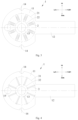
Fig. 1 is a schematic diagram of the current collector structure of embodiment I of the present disclosure in a top view; -
Fig. 2 is a sectional view of A-A inFig. 1 ; -
Fig. 3 is a schematic diagram of laser screw welding in the current collector structure of embodiment I of the present disclosure in a top view; -
Fig. 4 is a schematic diagram of laser spot welding in the current collector structure of embodiment I of the present disclosure in a top view; -
Fig. 5 is a schematic diagram of a surface with a groove structure in the current collector structure of embodiment II of the present disclosure in a top view; -
Fig. 6 is a sectional view of B-B inFig. 5 ; -
Fig. 7 is a schematic diagram of a surface of a protrusion structure in the current collector structure of embodiment II of the present disclosure in a top view; -
Fig. 8 is a sectional view of C-C inFig. 7 ; -
Fig. 9 is a schematic diagram of the current collector structure of embodiment III of the present disclosure in a top view; -
Fig. 10 is a schematic diagram of the current collector structure of embodiment IV of the present disclosure in a top view; -
Fig. 11 is a schematic diagram of the current collector structure of embodiment V of the present disclosure in a top view; and -
Fig. 12 is another schematic diagram of the current collector structure of embodiment V of the present disclosure in a top view. - Labels: 1 positive current collector; 11 current collector body; 111 positive current collecting area; 12 current collector leading-out tab; 13 center underflow hole; 14 peripheral underflow hole; 15 inner underflow hole; 16 protrusion; 17 groove; 18 electrolyte positive electrode infiltration channel; 2 laser screw welding; 21 screw welding outer boundary; 22 screw welding inner boundary; 3 laser spot welding; 31 spot welding outer boundary; 32 spot welding inner boundary; 4 negative current collector; 41 center solder joint set; 42 electrolyte negative electrode infiltration channel.
- In the description of the present disclosure, it is to be noted that the terms "up", "down", "front", "back", "left", "right", "vertical", "horizontal", "top", "bottom", "inside", "outside" and other orientation or position relationships are based on the orientation or position relationships shown in the attached drawings. It is only intended to facilitate description of the present disclosure and simplify description, but not to indicate or imply that the referred device or element has a specific orientation, or is constructed and operated in a specific orientation. Therefore, they should not be construed as a limitation of the present disclosure.
- Hereinafter, the current collector structure and the battery pack according to the embodiments of the present disclosure are described with reference to
Figs. 1-12 . Hereinafter, some embodiments of the present disclosure are described in detail with reference to the accompanying drawings. Without conflict, the following embodiments and the features in the embodiments can be combined with each other. - Compared with traditional batteries made of such as nickel-cadmium and lead-acid, lithium-ion batteries have the advantages of such as high energy density, high operating voltage, low self-discharge rate, long cycle life, high charging and discharging efficiency, wide operating temperature range, and low environmental pollution. At present, lithium-ion batteries have been widely used in mobile phones, notebooks and other 3C devices and new energy vehicles, and also have broad application prospects in civil aircraft, drones, space probes and other aerospace fields.
- At present, laser welding is often employed in lithium-ion batteries to weld the positive
current collector 1 and the exposed positive tab of the winding core. However, the forming process of the positivecurrent collector 1 in the prior art is relatively complicated, with arc-shaped, flanging and other structures, and there are multiple protrusions and one or more of groove structures, resulting in a small welding area, which is prone to poor welding problems, which allows potential improvements. - In view of this, proposed in the embodiments of the present disclosure is a current collector structure, which improves the structure of the positive
current collector 1, increases the welding contact area of the positivecurrent collector 1 and the positive tab of the winding core, is conducive to the welding stability of the positivecurrent collector 1, and reduces the occurrence of poor welding. - The following are different specific embodiments.
- According to
Figs. 1 to 4 , the current collector structure proposed in embodiment I of the present disclosure includes a positivecurrent collector 1. The positivecurrent collector 1 includes acurrent collector body 11 and a current collector leading-outtab 12 connected to each other. Thecurrent collector body 11 is provided with acenter underflow hole 13 through thecurrent collector body 11 in a thickness direction thereof, and an entire surface of a surface of thecurrent collector body 11 in the thickness direction is a welding surface, which is configured to weld with a positive tab of a winding core. - According to the present embodiment I, due to the existence of multiple protrusions and one or more of grooves in the existing current collector, it is unable to weld at the protrusions and grooves, which may result in a smaller welding area. However, the present current collector structure is simplified. In addition to setting the necessary center underflow holes 13, an entire surface of the
current collector body 11 itself can be employed to weld with the positive tabs of the winding core. An increase in the welding surface can effectively lead to an increase in the contact area with the positive tabs of the winding core, and can lead to an increase in the current-carrying area, which effectively improves the rate performance of the tabs, improves the current-carrying capacity of the battery, and reduces heat generation. In addition, the whole surface welding technology is adopted on thecurrent collector body 11, which is conducive to the welding stability of the current collector structure and reduces the occurrence of poor welding. At the same time, the present current collector structure is not only simple in structure, but also leads to an improvement in manufacturing efficiency, and also leads to a reduction in cost. - Specifically, the
center underflow hole 13 is aligned with the central hole of the winding core, which can ensure the fluid flowing condition to the greatest extent. Additionally and optionally, a diameter of thecenter underflow hole 13 is consistent with that of the central hole of the winding core. - Specifically, the current collector leading-out
tab 12 is connected to a cap in a cover plate assembly by laser welding, and thecurrent collector body 11 is welded to a surface of the positive tab of the winding core by laser line welding. Additionally and optionally, the positivecurrent collector 1 is made of aluminum, for example 1060-O aluminum. - Further, according to
Figs. 1 to 4 , one or more of peripheral underflow holes 14 are arranged at intervals along a perimeter of thecurrent collector body 11 at outer side. According to the present embodiment I, there are peripheral underflow holes 14 provided on a side of thecurrent collector body 11. During the liquid injection operation, the electrolyte first reaches thecurrent collector body 11, and then passes through thecenter underflow hole 13 into the winding core. In the present embodiment, in addition to thecenter underflow hole 13, theperipheral underflow hole 14 is also provided. Therefore, the electrolyte can simultaneously flow from thecenter underflow hole 13 and theperipheral underflow hole 14 into the winding core, which can assist in improving the liquid flowing capacity. Additionally and optionally, the shape of theperipheral underflow hole 14 is semi-circular. Admittedly, in some other embodiments, theperipheral underflow hole 14 may be square or half-oblong in shape. - Specifically, according to
Fig. 1 , provided are two peripheral underflow holes 14, and the two peripheral underflow holes 14 are respectively provided on an upper side and a lower side of thecurrent collector body 11. - Further, according to
Figs. 1 to 4 , thecurrent collector body 11 is provided with aninner underflow hole 15 through thecurrent collector body 11 in a thickness direction thereof, and theinner underflow hole 15 is provided on a side of thecenter underflow hole 13. According to the present embodiment I, there are inner underflow holes 15 provided on thecurrent collector body 11. During the liquid injection operation, the electrolyte first reaches thecurrent collector body 11, and then passes through thecenter underflow hole 13 into the winding core. In the present embodiment, in addition to thecenter underflow hole 13, theinner underflow hole 15 is also provided. Therefore, the electrolyte can simultaneously flow from thecenter underflow hole 13 and theinner underflow hole 15 into the winding core, which can assist in improving the liquid flowing capacity. Additionally and optionally, theinner underflow hole 15 is circular in shape. Admittedly, in some other embodiments, theinner underflow hole 15 may be square or oblong in shape. - Note that according to the present embodiment I, the entire surface of a surface of the
current collector body 11 in the thickness direction is a welding surface, which means that, except for thecenter underflow hole 13, theperipheral underflow hole 14, and theinner underflow hole 15 on thecurrent collector body 11, the remaining surfaces of thecurrent collector body 11 are employed to weld with the positive tabs of the winding core. - Further, according to
Fig. 4 , a welding surface of thecurrent collector body 11 is welded bylaser screw welding 2. According to the present embodiment I, since one or more of the laser screw welding 2 can effectively increase the welding area by forming a plurality of circular welding joints between the welding joints of the screw weld, the deformation of thecurrent collector body 11 can be suppressed and the rigidity of thecurrent collector body 11 can be improved due to an increase in the welding area. In addition, the welding energy is uniform, the shape, penetration depth and firmness of the welding joints are consistent, the appearance is smooth and beautiful with no deformation, and the welding is firm and reliable. - Specifically, one or more of the
laser screw welding 2 form a screw weldingouter boundary 21 and a screw weldinginner boundary 22, and a center of theinner underflow hole 15 is located on the screw weldingouter boundary 21. The screw weldingouter boundary 21 and the screw weldinginner boundary 22 are both circular and provided concentrically with thecenter underflow hole 13. The screw weldingouter boundary 21, the screw weldinginner boundary 22, and thecenter underflow hole 13 are sequentially arranged from the inside to the outside. Additionally and optionally, inner underflow holes 15 are provided between two adjacentlaser screw welding 2. - Admittedly, in some other embodiments, according to
Fig. 3 , a welding surface of thecurrent collector body 11 may also be welded bylaser spot welding 3. The laser spot welding has the advantages of such as fast speed, high accuracy, small heat input, small deformation in workpiece, precise control, small focus light point, high positioning accuracy, and easy automation. - Specifically, one or more of the
laser spot welding 3 form a spot weldingouter boundary 31 and a spot weldinginner boundary 32, and a center of theinner underflow hole 15 is located on the spot welding outer boundary 31.The spot weldingouter boundary 31 and the spot weldinginner boundary 32 are both circular and provided concentrically with thecenter underflow hole 13. The spot weldingouter boundary 31, the spot weldinginner boundary 32, and thecenter underflow hole 13 are sequentially arranged from the inside to the outside. Additionally and optionally, inner underflow holes 15 are provided between two adjacentlaser spot welding 3. - Proposed in the present embodiment of the disclosure is not only a current collector structure, but also a battery pack including the aforementioned current collector structure.
- According to
Figs. 5 to 8 , the current collector structure proposed in embodiment II of the present disclosure includes a positivecurrent collector 1. The positivecurrent collector 1 includes acurrent collector body 11 and a current collector leading-outtab 12 connected to each other. Thecurrent collector body 11 is provided with acenter underflow hole 13 through thecurrent collector body 11 in a thickness direction thereof, and an entire surface of a surface of thecurrent collector body 11 in the thickness direction is a welding surface, which is configured to weld with a positive tab of a winding core. - According to the present embodiment II, due to the existence of multiple protrusions and one or more of the grooves in the existing current collector, it is unable to weld at the protrusions and grooves, which may result in a smaller welding area. However, the present current collector structure is simplified. In addition to setting the necessary center underflow holes 13, an entire surface of the
current collector body 11 itself can be employed to weld with the positive tabs of the winding core. An increase in the welding surface can effectively lead to an increase in the contact area with the positive tabs of the winding core, and can lead to an increase in the current-carrying area, which effectively improves the rate performance of the tabs, improves the current-carrying capacity of the battery, and reduces heat generation. In addition, the whole surface welding technology is adopted on thecurrent collector body 11, which is conducive to the welding stability of the current collector structure and reduces the occurrence of poor welding. At the same time, the present current collector structure is not only simple in structure, but also leads to an improvement in manufacturing efficiency, and also leads to a reduction in cost. - Specifically, the
center underflow hole 13 is aligned with the central hole of the winding core, which can ensure the fluid flowing condition to the greatest extent. Additionally and optionally, a diameter of thecenter underflow hole 13 is consistent with that of the central hole of the winding core. - Specifically, the current collector leading-out
tab 12 is connected to a cap in a cover plate assembly by laser welding, and thecurrent collector body 11 is welded to a surface of the positive tab of the winding core by laser line welding. Additionally and optionally, the positivecurrent collector 1 is made of aluminum, for example 1060-O aluminum. - Further, according to
Figs. 5 to 8 , one or more of the peripheral underflow holes 14 are arranged at intervals along a perimeter of thecurrent collector body 11 at outer side. According to the present embodiment II, there are peripheral underflow holes 14 provided on a side of thecurrent collector body 11. During the liquid injection operation, the electrolyte first reaches thecurrent collector body 11, and then passes through thecenter underflow hole 13 into the winding core. In the present embodiment, in addition to thecenter underflow hole 13, theperipheral underflow hole 14 is also provided. Therefore, the electrolyte can simultaneously flow from thecenter underflow hole 13 and theperipheral underflow hole 14 into the winding core, which can assist in improving the liquid flowing capacity. Additionally and optionally, the shape of theperipheral underflow hole 14 is semi-circular. Admittedly, in some other embodiments, theperipheral underflow hole 14 may be square or half-oblong in shape. - Further, according to
Figs. 5 to 8 , two surfaces in a thickness direction of thecurrent collector body 11 are provided with aprotrusion 16 and agroove 17 correspondingly, thegroove 17 and theprotrusion 16 are aligned with each other and fit together in shape, theprotrusion 16 is arranged on a welding surface, and at least part of theprotrusion 16 extends to edges of thecurrent collector body 11. According to the present embodiment II, by setting theprotrusion 16 as the welding surface, the contact area between theprotrusion 16 and the positive tab of the winding core is large enough, that is, the sufficient welding area between thecurrent collector body 11 and the positive tab of the winding core can be retained, and the problem of poor welding can be effectively avoided. At the same time, compared with the whole surface welding, the welding efficiency can also be improved, thereby improving the manufacturing efficiency. Moreover, thegroove 17 provided on the surface of thecurrent collector body 11 plays a positioning role between thecurrent collector body 11 and the winding core, which is convenient for the staff to observe the position of theprotrusion 16 configured to weld. - Further, according to
Figs. 5 to 8 , one or more of theprotrusions 16 are provided and are in arc shapes, two ends of each of theprotrusion 16 extend to an edge of thecurrent collector body 11 to form a positive current collecting area 111 around an edge part of thecurrent collector body 11, and one or more of the peripheral underflow holes 14 are provided at one or more of the positive current collecting areas 111 correspondingly. According to the present embodiment II, theperipheral underflow hole 14 assists in improving the liquid flowing capacity, and thegroove 17 plays a positioning role between thecurrent collector body 11 and the winding core. Therefore, in order to avoid the problem of poor welding caused by the welding of theprotrusion 16 corresponding to thegroove 17, theperipheral underflow hole 14 is not arranged at thegroove 17, but is provided in the positive current collecting area 111, which can assist in improving the liquid flowing capacity and also ensure a sufficiently large contact area. - Specifically, according to
Figs. 5 to 8 , threeprotrusions 16 are provided on an upper side, a left side and a lower side of thecurrent collector body 11, and the threeprotrusions 16 are arranged in an annular array with thecenter underflow hole 13 as the center. Provided are also threegrooves 17 correspondingly, and the threegrooves 17 are also correspondingly arranged on the upper side, the left side and the lower side of thecurrent collector body 11, and the threegrooves 17 are also correspondingly arranged in an annular array with thecenter underflow hole 13 as the center. Correspondingly, provided are also three positive current collecting areas 111 surrounded by the threeprotrusions 16 and the threegrooves 17. In addition, provided are also three peripheral underflow holes 14, and the three peripheral underflow holes 14 are provided one by one at the three positive current collecting areas 111. - Proposed in the present embodiment of the disclosure is not only a current collector structure, but also a battery pack including the aforementioned current collector structure.
- According to
Fig. 9 , the current collector structure proposed in embodiment III of the present disclosure includes a positivecurrent collector 1. The positivecurrent collector 1 includes acurrent collector body 11 and a current collector leading-outtab 12 connected to each other. Thecurrent collector body 11 is provided with acenter underflow hole 13 through thecurrent collector body 11 in a thickness direction thereof, and an entire surface of a surface of thecurrent collector body 11 in the thickness direction is a welding surface configured to weld with a positive tab of a winding core. - According to the present embodiment III, due to the existence of multiple protrusions and one or more of grooves in the existing current collector, it is unable to weld at the protrusions and grooves, which may result in a smaller welding area. However, the present current collector structure is simplified. In addition to setting the necessary center underflow holes 13, an entire surface of the
current collector body 11 itself can be employed to weld with the positive tabs of the winding core. An increase in the welding surface can effectively lead to an increase in the contact area with the positive tabs of the winding core, and can lead to an increase in the current-carrying area, which effectively improves the rate performance of the tabs, improves the current-carrying capacity of the battery, and reduces heat generation. In addition, the whole surface welding technology is adopted on thecurrent collector body 11, which is conducive to the welding stability of the current collector structure and reduces the occurrence of poor welding. At the same time, the present current collector structure is not only simple in structure, but also leads to an improvement in manufacturing efficiency, and also leads to a reduction in cost. - Specifically, the
center underflow hole 13 is aligned with the central hole of the winding core, which can ensure the fluid flowing condition to the greatest extent. Additionally and optionally, a diameter of thecenter underflow hole 13 is consistent with that of the central hole of the winding core. - Specifically, the current collector leading-out
tab 12 is connected to a cap in a cover plate assembly by laser welding, and thecurrent collector body 11 is welded to a surface of the positive tab of the winding core by laser line welding. Additionally and optionally, the positivecurrent collector 1 is made of aluminum, for example 1060-O aluminum. - Further, according to
Fig. 9 , thecurrent collector body 11 is provided with one or more of electrolyte positiveelectrode infiltration channels 18 through thecurrent collector body 11 in a thickness direction thereof. According to the present embodiment III, the set electrolyte positiveelectrode infiltration channel 18 can lead to an increase in the transmission channel of the electrolyte in the cell and the exhaust channel for the thermal runaway, thus improving the injection efficiency and the exhaust rate when thermal runaway occurs in the cell. - Note that according to the present embodiment III, the entire surface of one surface of the
current collector body 11 in a thickness direction is the welding surface, which means that except for the electrolyte positiveelectrode infiltration channel 18, the remaining surfaces of thecurrent collector body 11 are employed to weld with the positive tab of the winding core. - Further, according to
Fig. 9 , one or more of the electrolyte positiveelectrode infiltration channels 18 are distributed in an annular array centered on thecenter underflow hole 13. An area between thecenter underflow hole 13 and one or more of the electrolyte positiveelectrode infiltration channels 18 is welded bylaser screw welding 2. According to the present embodiment III, since one or more of the laser screw welding 2 can effectively increase the welding area by forming a plurality of circular welding joints between the welding joints of the screw welding, the deformation of thecurrent collector body 11 can be suppressed and the rigidity of thecurrent collector body 11 can be improved due to an increase in the welding area. In addition, the welding energy is uniform, the shape, penetration depth and firmness of the welding joints are consistent, the appearance is smooth and beautiful with no deformation, and the welding is firm and reliable. - Specifically, according to
Fig. 9 , one or more of thelaser screw welding 2 form a screw weldingouter boundary 21 and a screw weldinginner boundary 22. The screw weldingouter boundary 21 and the screw weldinginner boundary 22 are both circular and provided concentrically with thecenter underflow hole 13. The screw weldingouter boundary 21, the screw weldinginner boundary 22, thecenter underflow hole 13 are sequentially arranged from the inside to the outside, and one or more of the electrolyte positiveelectrode infiltration channels 18 are provided outside the screw weldingouter boundary 21. - Admittedly, in some other embodiments, an area between the
center underflow hole 13 and one or more of the electrolyte positiveelectrode infiltration channels 18 may be welded bylaser spot welding 3. One or more of thelaser spot welds 3 form a spot weldingouter boundary 31 and a spot weldinginner boundary 32, the spot weldingouter boundary 31 and the spot weldinginner boundary 32 are circular and provided concentrically with thecenter underflow hole 13, and one or more of the electrolyte positiveelectrode infiltration channels 18 are provided outside the spot weldingouter boundary 31. - Proposed in the present embodiment of the disclosure is not only a current collector structure, but also a battery pack including the aforementioned current collector structure.
- According to
Fig. 10 , the current collector structure proposed in embodiment IV of the present disclosure includes a positivecurrent collector 1. The positivecurrent collector 1 includes acurrent collector body 11 and a current collector leading-outtab 12 connected to each other. Thecurrent collector body 11 is provided with acenter underflow hole 13 through thecurrent collector body 11 in a thickness direction thereof, and an entire surface of a surface of thecurrent collector body 11 in the thickness direction is a welding surface configured to weld with a positive tab of a winding core. - According to the present embodiment IV, due to the existence of multiple protrusions and one or more of grooves in the existing current collector, it is unable to weld at the protrusions and grooves, which may result in a smaller welding area. However, the present current collector structure is simplified. In addition to setting the necessary center underflow holes 13, an entire surface of the
current collector body 11 itself can be employed to weld with the positive tabs of the winding core. An increase in the welding surface can effectively lead to an increase in the contact area with the positive tabs of the winding core, and can lead to an increase in the current-carrying area, which effectively improves the rate performance of the tabs, improves the current-carrying capacity of the battery, and reduces heat generation. In addition, the whole surface welding technology is adopted on thecurrent collector body 11, which is conducive to the welding stability of the current collector structure and reduces the occurrence of poor welding. At the same time, the present current collector structure is not only simple in structure, but also leads to an improvement in manufacturing efficiency, and also leads to a reduction in cost. - Specifically, the
center underflow hole 13 is aligned with the central hole of the winding core, which can ensure the fluid flowing condition to the greatest extent. Additionally and optionally, a diameter of thecenter underflow hole 13 is consistent with that of the central hole of the winding core. - Specifically, the current collector leading-out
tab 12 is connected to a cap in a cover plate assembly by laser welding, and thecurrent collector body 11 is welded to a surface of the positive tab of the winding core by laser line welding. Additionally and optionally, the positivecurrent collector 1 is made of aluminum, for example 1060-O aluminum. - Further, according to
Fig. 10 , thecurrent collector body 11 is provided with one or more of electrolyte positiveelectrode infiltration channels 18 through thecurrent collector body 11 in a thickness direction thereof. According to the present embodiment IV, the set electrolyte positiveelectrode infiltration channel 18 can lead to an increase in the transmission channel of the electrolyte in the cell and the exhaust channel for the thermal runaway, thus improving the injection efficiency and the exhaust rate when thermal runaway occurs in the cell. - Further, according
Fig. 10 , two surfaces of thecurrent collector body 11 in a thickness direction of thecurrent collector body 11 are provided with aprotrusion 16 and agroove 17 correspondingly, thegroove 17 and theprotrusion 16 are aligned and set in a same shape, and theprotrusion 16 is arranged on a welding surface; one or more ofprotrusions 16 are provided and are in arc shapes, two ends of each of theprotrusions 16 extend to an edge of thecurrent collector body 11, and one electrolyte positiveelectrode infiltration channel 18 is provided between twoadjacent protrusions 16. According to the present embodiment IV, the electrolyte positiveelectrode infiltration channel 18 assists in improving the injection efficiency, and thegroove 17 plays a positioning role between thecurrent collector body 11 and the winding core. Therefore, in order to avoid the problem of poor welding caused by the welding of theprotrusion 16 corresponding to thegroove 17, the electrolyte positiveelectrode infiltration channel 18 is not provided at theprotrusion 16, but is provided between twoadjacent protrusions 16, which can assist in improving the injection efficiency and also ensure a sufficiently large contact area. - Proposed in the present embodiment of the disclosure is not only a current collector structure, but also a battery pack including the aforementioned current collector structure.
- According to
Figs. 11 and12 , the current collector structure proposed in embodiment V of the present disclosure includes a positivecurrent collector 1. The positivecurrent collector 1 includes acurrent collector body 11 and a current collector leading-outtab 12 connected to each other. Thecurrent collector body 11 is provided with acenter underflow hole 13 through thecurrent collector body 11 in a thickness direction thereof, and an entire surface of a surface of thecurrent collector body 11 in the thickness direction is a welding surface configured to weld with a positive tab of a winding core. - According to the present embodiment V, due to the existence of multiple protrusions and one or more of grooves in the existing current collector, it is unable to weld at the protrusions and grooves, which may result in a smaller welding area. However, the present current collector structure is simplified. In addition to setting the necessary center underflow holes 13, an entire surface of the
current collector body 11 itself can be employed to weld with the positive tabs of the winding core. An increase in the welding surface can effectively lead to an increase in the contact area with the positive tabs of the winding core, lead to an increase in the current-carrying area, which effectively improves the rate performance of the tabs, improves the current-carrying capacity of the battery, and reduces heat generation. In terms of structural design, the whole surface welding technology is adopted on thecurrent collector body 11, which is conducive to the welding stability of the current collector structure and reduces the occurrence of poor welding. At the same time, the present current collector structure is not only simple in structure, but also leads to an improvement in manufacturing efficiency, and a reduction in cost. - Specifically, the
center underflow hole 13 is aligned with the central hole of the winding core, which can ensure the fluid flowing condition to the greatest extent. Additionally and optionally, a diameter of thecenter underflow hole 13 is consistent with that of the central hole of the winding core. - Specifically, the current collector leading-out
tab 12 is connected to a cap in a cover plate assembly by laser welding, and thecurrent collector body 11 is welded to a surface of the positive tab of the winding core by laser line welding. Additionally and optionally, the positivecurrent collector 1 is made of aluminum, for example 1060-O aluminum. - Further, according to
Fig. 11 , the current collector structure further includes a negativecurrent collector 4, the negativecurrent collector 4 is provided with an center solder j oint set 41 at a center of a surface in a thickness direction thereof, the solder joints of the center solder joint set 41 are distributed in at least two rows in a first direction, the solder joints in each row are distributed with an interval, and the solder joints in adjacent rows are misaligned. The first direction refers to the up and down direction indicated by the coordinate system inFig. 11 . - According to the present embodiment V, the current collector structure is simple, and the center of the negative
current collector 4 is designed with a unique welding structure of misalignment embossing, which maximally guarantees the welding area of the negativecurrent collector 4. Moreover, spot welding is performed using resistance welding, which provides strong welds with good stability. - Further, according to
Fig. 12 , the negativecurrent collector 4 is provided with one or more of electrolyte negativeelectrode infiltration channels 42 through the negativecurrent collector 4 in a thickness direction thereof. Additionally and optionally, provided are four electrolytenegative infiltration channels 42, and the four electrolytenegative infiltration channels 42 are provided on the upper side, the left side, the lower side, and the right side of the negativecurrent collector 4. According to the present embodiment V, while retaining sufficient welding area between the negativecurrent collector 4 and the tab, the set electrolyte negativeelectrode infiltration channel 42 can lead to an increase in the transmission channel of the electrolyte in the cell and the exhaust channel for the thermal runaway, thus improving the injection efficiency and the exhaust rate when thermal runaway occurs in the cell. - Further, according to
Fig. 12 , one or more of the electrolyte negativeelectrode infiltration channels 42 are distributed in an annular array centered on a center solder joint set 41, and an area between two adjacent electrolyte negativeelectrode infiltration channels 42 is welded bylaser screw welding 2. According to the present embodiment V, since one or more of the laser screw welding 2 can effectively increase the welding area by forming a plurality of circular welding joints between the welding joints of the spot weld, the deformation of thecurrent collector body 11 can be suppressed and the rigidity of thecurrent collector body 11 can be improved due to an increase in the welding area. In addition, the welding energy is uniform, the shape, penetration depth and firmness of the welding joints are consistent, the appearance is smooth and beautiful with no deformation, and the welding is firm and reliable. - Admittedly, in some other embodiments, an area between two adjacent electrolyte negative
electrode infiltration channels 42 may be welded bylaser spot welding 3. The laser spot welding has the advantages of such as fast speed, high accuracy, small heat input, small deformation in workpiece, precise control, small focus light point, high positioning accuracy, and easy automation. - Specifically, one or more of the electrolyte negative
electrode infiltration channels 42 are circular, a negative electrode infiltration channel boundary is formed by connecting the centers of one or more of the negativeelectrode infiltration channels 42, and one or more of the laser screw welding 2 or one or more of thelaser spot welding 3 passes through the negative electrode infiltration channel boundary. - Proposed in the present embodiment of the disclosure is not only a current collector structure, but also a battery pack including the aforementioned current collector structure.
Claims (15)
- A current collector structure, comprising a positive current collector (1), wherein the positive current collector comprises a current collector body (11) and a current collector leading-out tab (12) connected to each other;wherein the current collector body (11) is provided with a center underflow hole (13) through the current collector body (11) in a thickness direction thereof, andan entire surface of a surface of the current collector body (11) in the thickness direction is a welding surface configured to weld with a positive tab of a winding core.
- The current collector structure according to claim 1, wherein one or more of peripheral underflow holes (14) are arranged at intervals along a perimeter of the current collector body (11) at outer side.
- The current collector structure according to claim 2, wherein the current collector body (11) is provided with an inner underflow hole (15) in a thickness direction of the current collector body (11), and the inner underflow hole (15) is arranged on a side of the center underflow hole (13).
- The current collector structure according to claim 3, wherein the welding surface of the current collector body (11) is welded by laser screw welding (2) or laser spot welding (3).
- The current collector structure according to claim 4, wherein one or more of the laser screw welding (2) form a screw welding outer boundary (21) and a screw welding inner boundary (22), the screw welding outer boundary (21) and the screw welding inner boundary (22) are circular and provided concentrically with the center underflow hole (13), and a center of the inner underflow hole (15) is located on the screw welding outer boundary (21); or
one or more of the laser spot welding (3) forms a spot welding outer boundary (31) and a spot welding inner boundary (32), the spot welding outer boundary (31) and the spot welding inner boundary (32) are circular and provided concentrically with the center underflow hole (13), and a center of the inner underflow hole (15) is located on the spot welding outer boundary (31). - The current collector structure according to claim 2, wherein two surfaces of the current collector body (11) in a thickness direction of the current collector body (11) are provided with a protrusion (16) and a groove (17) correspondingly, the groove (17) and the protrusion (16) are aligned with each other and fit together in shape, the protrusion (16) is arranged on a welding surface, and at least part of the protrusion (16) extends to edges of the current collector body (11).
- The current collector structure according to claim 6, wherein one or more of the protrusions (16) are provided and are in arc shapes, two ends of each of the protrusions (16) extend to an edge of the current collector body (11) to form a positive current collecting area (111) around an edge part of the current collector body (11), and one or more of the peripheral underflow holes (14) are provided at one or more of the positive current collecting areas (111) correspondingly.
- The current collector structure according to claim 1, wherein the current collector body (11) is provided with one or more of electrolyte positive electrode infiltration channels (18) through the current collector body (11) in the thickness direction thereof.
- The current collector structure according to claim 8, wherein one or more of the electrolyte positive electrode infiltration channels (18) are distributed in an annular array centered on the center underflow hole (13); and
an area between the center underflow hole (13) and one or more of the electrolyte positive electrode infiltration channels (18) is welded by laser screw welding (2) or laser spot welding (3). - The current collector structure according to claim 9, wherein one or more of the laser screw welding (2) form a screw welding outer boundary (21) and a screw welding inner boundary (22), the screw welding outer boundary (21) and the screw welding inner boundary (22) are circular and provided concentrically with the center underflow hole (13), and one or more of the electrolyte positive electrode infiltration channels (18) are provided outside the screw welding outer boundary (21); or
one or more of the laser spot welding (3) form a spot welding outer boundary (31) and a spot welding inner boundary (32), the spot welding outer boundary (31) and the spot welding inner boundary (32) are circular and provided concentrically with the center underflow hole (13), and one or more of the electrolyte positive electrode infiltration channels (18) are provided outside the spot welding outer boundary (31). - The current collector structure according to claim 8, wherein two surfaces of the current collector body (11) in a thickness direction of the current collector body (11) are provided with a protrusion (16) and a groove (17) correspondingly, the groove (17) and the protrusion (16) are aligned with each other and fit together in shape, the protrusion (16) is arranged on a welding surface;
one or more of protrusions (16) are provided and are in arc shapes, two ends of each protrusion (16) extend to an edge of the current collector body (11), and one electrolyte positive electrode infiltration channel (18) is provided between two adjacent protrusions (16). - The current collector structure according to claim 1, further comprising a negative current collector (4), wherein the negative current collector (4) is provided with an center solder joint set (41) at a center of a surface in a thickness direction thereof, solder joints of the center solder joint set (41) are distributed in at least two rows in a first direction, the solder joints in each row are distributed with an interval, and the solder joints in adjacent rows are misaligned.
- The current collector structure according to claim 12, wherein the negative current collector (4) is provided with one or more of electrolyte negative electrode infiltration channels (42) through the negative current collector (4) in the thickness direction thereof.
- The current collector structure according to claim 13, wherein one or more of the electrolyte negative electrode infiltration channels (42) are distributed in an annular array centered on the center solder joint set (41); and
an area between two adjacent electrolyte negative electrode infiltration channels (42) is welded by laser screw welding (2) or laser spot welding (3). - A battery pack, wherein the battery pack comprises the current collector structure according to any one of claims 1-14.
Applications Claiming Priority (3)
| Application Number | Priority Date | Filing Date | Title |
|---|---|---|---|
| CN202320203233.6U CN219873942U (en) | 2023-02-10 | 2023-02-10 | Converging disc structure and battery pack |
| CN202310108818.4A CN116111289A (en) | 2023-02-10 | 2023-02-10 | Converging disc structure and battery pack |
| PCT/CN2023/080722 WO2024164385A1 (en) | 2023-02-10 | 2023-03-10 | Disc busbar structure and battery pack |
Publications (2)
| Publication Number | Publication Date |
|---|---|
| EP4531194A1 true EP4531194A1 (en) | 2025-04-02 |
| EP4531194A4 EP4531194A4 (en) | 2025-12-24 |
Family
ID=92261919
Family Applications (1)
| Application Number | Title | Priority Date | Filing Date |
|---|---|---|---|
| EP23920591.7A Pending EP4531194A4 (en) | 2023-02-10 | 2023-03-10 | DISC COLLECTION RAIL STRUCTURE AND BATTERY PACK |
Country Status (5)
| Country | Link |
|---|---|
| US (1) | US20250132468A1 (en) |
| EP (1) | EP4531194A4 (en) |
| JP (1) | JP2025519120A (en) |
| DE (1) | DE212023000253U1 (en) |
| WO (1) | WO2024164385A1 (en) |
Cited By (1)
| Publication number | Priority date | Publication date | Assignee | Title |
|---|---|---|---|---|
| EP4593167A3 (en) * | 2024-01-29 | 2025-10-29 | Techtronic Cordless GP | Current collector with embossed bumps |
Family Cites Families (8)
| Publication number | Priority date | Publication date | Assignee | Title |
|---|---|---|---|---|
| JP3819570B2 (en) * | 1997-11-18 | 2006-09-13 | 三洋電機株式会社 | Cylindrical alkaline storage battery using non-sintered electrodes |
| JP2007335156A (en) * | 2006-06-13 | 2007-12-27 | Honda Motor Co Ltd | Electricity storage element |
| CN203674314U (en) * | 2013-12-24 | 2014-06-25 | 益阳科力远电池有限责任公司 | Current collecting device for circular battery |
| CN204966575U (en) * | 2015-06-17 | 2016-01-13 | 深圳市沃特玛电池有限公司 | Lithium cell edge weld utmost point ear piece that converges |
| CN111900274A (en) * | 2020-08-04 | 2020-11-06 | 珠海冠宇电池股份有限公司 | Button cell and preparation method thereof |
| CN216624504U (en) * | 2021-09-16 | 2022-05-27 | 东莞市创明电池技术有限公司 | Full-lug cylindrical lithium ion battery |
| CN114361729B (en) * | 2022-01-12 | 2024-09-06 | 广州小鹏汽车科技有限公司 | Battery cell |
| CN216872214U (en) * | 2022-03-02 | 2022-07-01 | 江西远东电池有限公司 | Novel cylindrical battery current collecting disc structure |
-
2023
- 2023-03-10 JP JP2024569349A patent/JP2025519120A/en active Pending
- 2023-03-10 EP EP23920591.7A patent/EP4531194A4/en active Pending
- 2023-03-10 WO PCT/CN2023/080722 patent/WO2024164385A1/en not_active Ceased
- 2023-03-10 DE DE212023000253.1U patent/DE212023000253U1/en active Active
-
2024
- 2024-12-27 US US19/002,835 patent/US20250132468A1/en active Pending
Cited By (1)
| Publication number | Priority date | Publication date | Assignee | Title |
|---|---|---|---|---|
| EP4593167A3 (en) * | 2024-01-29 | 2025-10-29 | Techtronic Cordless GP | Current collector with embossed bumps |
Also Published As
| Publication number | Publication date |
|---|---|
| EP4531194A4 (en) | 2025-12-24 |
| JP2025519120A (en) | 2025-06-24 |
| US20250132468A1 (en) | 2025-04-24 |
| WO2024164385A1 (en) | 2024-08-15 |
| DE212023000253U1 (en) | 2025-02-03 |
Similar Documents
| Publication | Publication Date | Title |
|---|---|---|
| US20230411808A1 (en) | Electrode Terminal, Current Collecting Assembly and Cylindrical Battery | |
| US20230121494A1 (en) | Electrode assembly for battery and battery | |
| CN212136595U (en) | Current collecting assembly and large-capacity battery manufactured by same | |
| US20240213630A1 (en) | Lithium battery and method for preparing lithium battery | |
| US20250132468A1 (en) | Current collector structure and battery pack | |
| CN219873942U (en) | Converging disc structure and battery pack | |
| CN115395145A (en) | A cylindrical battery | |
| CN115513514A (en) | A single battery and its preparation method | |
| CN112054236A (en) | Storage battery and manufacturing method thereof | |
| US20260051584A1 (en) | Battery cell, method for preparing battery cell, battery, and electrical apparatus | |
| CN218334025U (en) | Lithium battery top cover assembly | |
| CN218215613U (en) | Battery post structure easy to be connected with tab | |
| CN116111289A (en) | Converging disc structure and battery pack | |
| CN215220771U (en) | Metal bipolar plate structure | |
| CN222940110U (en) | Battery module case lid and battery module | |
| CN221407360U (en) | A negative electrode current collecting plate of a cylindrical battery and a battery | |
| CN219553837U (en) | Battery post and battery pack | |
| CN209071548U (en) | A kind of no-welding battery | |
| CN219226323U (en) | Non-uniform thickness current collecting disc, battery cap and battery | |
| CN116190929B (en) | Collector plates and battery cells | |
| CN219419248U (en) | Battery | |
| CN222562922U (en) | Confluence sheet | |
| CN203746958U (en) | Lithium battery end face welded current collector | |
| CN212485371U (en) | Current collecting assembly and battery manufactured by same | |
| CN221841885U (en) | Lithium battery |
Legal Events
| Date | Code | Title | Description |
|---|---|---|---|
| STAA | Information on the status of an ep patent application or granted ep patent |
Free format text: STATUS: THE INTERNATIONAL PUBLICATION HAS BEEN MADE |
|
| PUAI | Public reference made under article 153(3) epc to a published international application that has entered the european phase |
Free format text: ORIGINAL CODE: 0009012 |
|
| STAA | Information on the status of an ep patent application or granted ep patent |
Free format text: STATUS: REQUEST FOR EXAMINATION WAS MADE |
|
| 17P | Request for examination filed |
Effective date: 20241227 |
|
| AK | Designated contracting states |
Kind code of ref document: A1 Designated state(s): AL AT BE BG CH CY CZ DE DK EE ES FI FR GB GR HR HU IE IS IT LI LT LU LV MC ME MK MT NL NO PL PT RO RS SE SI SK SM TR |
|
| A4 | Supplementary search report drawn up and despatched |
Effective date: 20251121 |
|
| RIC1 | Information provided on ipc code assigned before grant |
Ipc: H01M 50/505 20210101AFI20251117BHEP Ipc: H01M 50/528 20210101ALI20251117BHEP Ipc: H01M 50/503 20210101ALI20251117BHEP Ipc: H01M 50/536 20210101ALI20251117BHEP |