EP4531191A1 - Rechargeable battery - Google Patents
Rechargeable battery Download PDFInfo
- Publication number
- EP4531191A1 EP4531191A1 EP24190846.6A EP24190846A EP4531191A1 EP 4531191 A1 EP4531191 A1 EP 4531191A1 EP 24190846 A EP24190846 A EP 24190846A EP 4531191 A1 EP4531191 A1 EP 4531191A1
- Authority
- EP
- European Patent Office
- Prior art keywords
- cell stack
- rechargeable battery
- electrode assembly
- edge
- pair
- Prior art date
- Legal status (The legal status is an assumption and is not a legal conclusion. Google has not performed a legal analysis and makes no representation as to the accuracy of the status listed.)
- Pending
Links
Images






Classifications
-
- H—ELECTRICITY
- H01—ELECTRIC ELEMENTS
- H01M—PROCESSES OR MEANS, e.g. BATTERIES, FOR THE DIRECT CONVERSION OF CHEMICAL ENERGY INTO ELECTRICAL ENERGY
- H01M50/00—Constructional details or processes of manufacture of the non-active parts of electrochemical cells other than fuel cells, e.g. hybrid cells
- H01M50/20—Mountings; Secondary casings or frames; Racks, modules or packs; Suspension devices; Shock absorbers; Transport or carrying devices; Holders
- H01M50/233—Mountings; Secondary casings or frames; Racks, modules or packs; Suspension devices; Shock absorbers; Transport or carrying devices; Holders characterised by physical properties of casings or racks, e.g. dimensions
-
- H—ELECTRICITY
- H01—ELECTRIC ELEMENTS
- H01M—PROCESSES OR MEANS, e.g. BATTERIES, FOR THE DIRECT CONVERSION OF CHEMICAL ENERGY INTO ELECTRICAL ENERGY
- H01M10/00—Secondary cells; Manufacture thereof
- H01M10/04—Construction or manufacture in general
- H01M10/0481—Compression means other than compression means for stacks of electrodes and separators
-
- H—ELECTRICITY
- H01—ELECTRIC ELEMENTS
- H01M—PROCESSES OR MEANS, e.g. BATTERIES, FOR THE DIRECT CONVERSION OF CHEMICAL ENERGY INTO ELECTRICAL ENERGY
- H01M50/00—Constructional details or processes of manufacture of the non-active parts of electrochemical cells other than fuel cells, e.g. hybrid cells
- H01M50/10—Primary casings; Jackets or wrappings
- H01M50/102—Primary casings; Jackets or wrappings characterised by their shape or physical structure
- H01M50/105—Pouches or flexible bags
-
- H—ELECTRICITY
- H01—ELECTRIC ELEMENTS
- H01M—PROCESSES OR MEANS, e.g. BATTERIES, FOR THE DIRECT CONVERSION OF CHEMICAL ENERGY INTO ELECTRICAL ENERGY
- H01M10/00—Secondary cells; Manufacture thereof
- H01M10/05—Accumulators with non-aqueous electrolyte
- H01M10/058—Construction or manufacture
- H01M10/0585—Construction or manufacture of accumulators having only flat construction elements, i.e. flat positive electrodes, flat negative electrodes and flat separators
-
- H—ELECTRICITY
- H01—ELECTRIC ELEMENTS
- H01M—PROCESSES OR MEANS, e.g. BATTERIES, FOR THE DIRECT CONVERSION OF CHEMICAL ENERGY INTO ELECTRICAL ENERGY
- H01M10/00—Secondary cells; Manufacture thereof
- H01M10/42—Methods or arrangements for servicing or maintenance of secondary cells or secondary half-cells
-
- H—ELECTRICITY
- H01—ELECTRIC ELEMENTS
- H01M—PROCESSES OR MEANS, e.g. BATTERIES, FOR THE DIRECT CONVERSION OF CHEMICAL ENERGY INTO ELECTRICAL ENERGY
- H01M50/00—Constructional details or processes of manufacture of the non-active parts of electrochemical cells other than fuel cells, e.g. hybrid cells
- H01M50/20—Mountings; Secondary casings or frames; Racks, modules or packs; Suspension devices; Shock absorbers; Transport or carrying devices; Holders
- H01M50/262—Mountings; Secondary casings or frames; Racks, modules or packs; Suspension devices; Shock absorbers; Transport or carrying devices; Holders with fastening means, e.g. locks
- H01M50/264—Mountings; Secondary casings or frames; Racks, modules or packs; Suspension devices; Shock absorbers; Transport or carrying devices; Holders with fastening means, e.g. locks for cells or batteries, e.g. straps, tie rods or peripheral frames
-
- H—ELECTRICITY
- H01—ELECTRIC ELEMENTS
- H01M—PROCESSES OR MEANS, e.g. BATTERIES, FOR THE DIRECT CONVERSION OF CHEMICAL ENERGY INTO ELECTRICAL ENERGY
- H01M50/00—Constructional details or processes of manufacture of the non-active parts of electrochemical cells other than fuel cells, e.g. hybrid cells
- H01M50/40—Separators; Membranes; Diaphragms; Spacing elements inside cells
- H01M50/46—Separators, membranes or diaphragms characterised by their combination with electrodes
-
- H—ELECTRICITY
- H01—ELECTRIC ELEMENTS
- H01M—PROCESSES OR MEANS, e.g. BATTERIES, FOR THE DIRECT CONVERSION OF CHEMICAL ENERGY INTO ELECTRICAL ENERGY
- H01M50/00—Constructional details or processes of manufacture of the non-active parts of electrochemical cells other than fuel cells, e.g. hybrid cells
- H01M50/40—Separators; Membranes; Diaphragms; Spacing elements inside cells
- H01M50/463—Separators, membranes or diaphragms characterised by their shape
- H01M50/466—U-shaped, bag-shaped or folded
-
- H—ELECTRICITY
- H01—ELECTRIC ELEMENTS
- H01M—PROCESSES OR MEANS, e.g. BATTERIES, FOR THE DIRECT CONVERSION OF CHEMICAL ENERGY INTO ELECTRICAL ENERGY
- H01M50/00—Constructional details or processes of manufacture of the non-active parts of electrochemical cells other than fuel cells, e.g. hybrid cells
- H01M50/40—Separators; Membranes; Diaphragms; Spacing elements inside cells
- H01M50/471—Spacing elements inside cells other than separators, membranes or diaphragms; Manufacturing processes thereof
- H01M50/474—Spacing elements inside cells other than separators, membranes or diaphragms; Manufacturing processes thereof characterised by their position inside the cells
-
- H—ELECTRICITY
- H01—ELECTRIC ELEMENTS
- H01M—PROCESSES OR MEANS, e.g. BATTERIES, FOR THE DIRECT CONVERSION OF CHEMICAL ENERGY INTO ELECTRICAL ENERGY
- H01M50/00—Constructional details or processes of manufacture of the non-active parts of electrochemical cells other than fuel cells, e.g. hybrid cells
- H01M50/40—Separators; Membranes; Diaphragms; Spacing elements inside cells
- H01M50/471—Spacing elements inside cells other than separators, membranes or diaphragms; Manufacturing processes thereof
- H01M50/477—Spacing elements inside cells other than separators, membranes or diaphragms; Manufacturing processes thereof characterised by their shape
-
- H—ELECTRICITY
- H01—ELECTRIC ELEMENTS
- H01M—PROCESSES OR MEANS, e.g. BATTERIES, FOR THE DIRECT CONVERSION OF CHEMICAL ENERGY INTO ELECTRICAL ENERGY
- H01M50/00—Constructional details or processes of manufacture of the non-active parts of electrochemical cells other than fuel cells, e.g. hybrid cells
- H01M50/40—Separators; Membranes; Diaphragms; Spacing elements inside cells
- H01M50/471—Spacing elements inside cells other than separators, membranes or diaphragms; Manufacturing processes thereof
- H01M50/48—Spacing elements inside cells other than separators, membranes or diaphragms; Manufacturing processes thereof characterised by the material
- H01M50/486—Organic material
-
- H—ELECTRICITY
- H01—ELECTRIC ELEMENTS
- H01M—PROCESSES OR MEANS, e.g. BATTERIES, FOR THE DIRECT CONVERSION OF CHEMICAL ENERGY INTO ELECTRICAL ENERGY
- H01M50/00—Constructional details or processes of manufacture of the non-active parts of electrochemical cells other than fuel cells, e.g. hybrid cells
- H01M50/50—Current conducting connections for cells or batteries
- H01M50/531—Electrode connections inside a battery casing
- H01M50/533—Electrode connections inside a battery casing characterised by the shape of the leads or tabs
-
- H—ELECTRICITY
- H01—ELECTRIC ELEMENTS
- H01M—PROCESSES OR MEANS, e.g. BATTERIES, FOR THE DIRECT CONVERSION OF CHEMICAL ENERGY INTO ELECTRICAL ENERGY
- H01M50/00—Constructional details or processes of manufacture of the non-active parts of electrochemical cells other than fuel cells, e.g. hybrid cells
- H01M50/50—Current conducting connections for cells or batteries
- H01M50/531—Electrode connections inside a battery casing
- H01M50/54—Connection of several leads or tabs of plate-like electrode stacks, e.g. electrode pole straps or bridges
-
- H—ELECTRICITY
- H01—ELECTRIC ELEMENTS
- H01M—PROCESSES OR MEANS, e.g. BATTERIES, FOR THE DIRECT CONVERSION OF CHEMICAL ENERGY INTO ELECTRICAL ENERGY
- H01M50/00—Constructional details or processes of manufacture of the non-active parts of electrochemical cells other than fuel cells, e.g. hybrid cells
- H01M50/50—Current conducting connections for cells or batteries
- H01M50/543—Terminals
- H01M50/552—Terminals characterised by their shape
- H01M50/553—Terminals adapted for prismatic, pouch or rectangular cells
-
- Y—GENERAL TAGGING OF NEW TECHNOLOGICAL DEVELOPMENTS; GENERAL TAGGING OF CROSS-SECTIONAL TECHNOLOGIES SPANNING OVER SEVERAL SECTIONS OF THE IPC; TECHNICAL SUBJECTS COVERED BY FORMER USPC CROSS-REFERENCE ART COLLECTIONS [XRACs] AND DIGESTS
- Y02—TECHNOLOGIES OR APPLICATIONS FOR MITIGATION OR ADAPTATION AGAINST CLIMATE CHANGE
- Y02E—REDUCTION OF GREENHOUSE GAS [GHG] EMISSIONS, RELATED TO ENERGY GENERATION, TRANSMISSION OR DISTRIBUTION
- Y02E60/00—Enabling technologies; Technologies with a potential or indirect contribution to GHG emissions mitigation
- Y02E60/10—Energy storage using batteries
-
- Y—GENERAL TAGGING OF NEW TECHNOLOGICAL DEVELOPMENTS; GENERAL TAGGING OF CROSS-SECTIONAL TECHNOLOGIES SPANNING OVER SEVERAL SECTIONS OF THE IPC; TECHNICAL SUBJECTS COVERED BY FORMER USPC CROSS-REFERENCE ART COLLECTIONS [XRACs] AND DIGESTS
- Y02—TECHNOLOGIES OR APPLICATIONS FOR MITIGATION OR ADAPTATION AGAINST CLIMATE CHANGE
- Y02P—CLIMATE CHANGE MITIGATION TECHNOLOGIES IN THE PRODUCTION OR PROCESSING OF GOODS
- Y02P70/00—Climate change mitigation technologies in the production process for final industrial or consumer products
- Y02P70/50—Manufacturing or production processes characterised by the final manufactured product
Definitions
- Embodiments relate to a rechargeable battery, and more particularly, to a structure of a stacked electrode assembly.
- Rechargeable batteries which are capable of being charged, are used for various purposes such as power sources for small-scale electronic devices, such as mobile phones and notebook computers, and power sources for driving motors of transportation means such as electric vehicles and hybrid vehicles.
- the rechargeable battery basically includes an electrode assembly and a casing for accommodating and sealing the electrode assembly.
- the rechargeable batteries may be classified into a cylindrical battery, an angular battery, a pouch-type battery, and the like depending on external shapes of the rechargeable batteries.
- the electrode assembly may be configured by alternately stacking a plurality of positive electrodes and a plurality of negative electrodes one by one with separators interposed therebetween.
- the positive electrode and the negative electrode may each include a substrate and composite material layers positioned on two opposite surfaces of the substrate.
- a non-uniform thickness may occur during a process of manufacturing the composite material layer.
- the non-uniform thickness of the composite material layer causes a non-uniform thickness of the electrode assembly.
- joining forces between the positive electrode, the separator, and the negative electrode are decreased, which may degrade output characteristics and output stability of the rechargeable battery.
- Embodiments include a rechargeable battery.
- the rechargeable battery includes an electrode assembly and a casing configured to accommodate and seal the electrode assembly, wherein the electrode assembly includes a cell stack including a plurality of first electrodes and a plurality of second electrodes alternately stacked one by one with a separator interposed therebetween, the cell stack including a first part having a first thickness, and a second part having a second thickness smaller than the first thickness.
- a correction sheet is positioned on the second part and uniformizes a thickness of the cell stack.
- a pair of first fixing parts is positioned over a front surface, a lateral surface and a rear surface of the cell stack, the pair of first fixing parts having a portion that overlaps the correction sheet.
- the correction sheet may include a pair of correction sheets respectively positioned on a front surface and a rear surface of the second part.
- Each of the pair of correction sheets may be configured as a polymer film having an adhesive layer.
- the cell stack may have a uniform thickness by being pressed by a thermal press device after the correction sheet is attached to the second part.
- the cell stack may include a first edge and second and third edges intersecting the first edge, a plurality of first tabs extending from the plurality of first electrodes and a plurality of second tabs extending from the plurality of second electrodes at the first edge, and the second part and the correction sheet may be positioned to adjoin the first edge.
- the second part and the correction sheet may each have a width equal to a width of the cell stack.
- the pair of first fixing parts may be positioned over the front surface, the lateral surface and the rear surface of the cell stack at the second and third edges and may overlap the correction sheet on at least one of the front surface and the rear surface of the cell stack.
- the cell stack may include a fourth edge parallel to the first edge and intersecting the second and third edges, and the electrode assembly may further include a second fixing part positioned over the front surface, the lateral surface and the rear surface of the cell stack at the fourth edge.
- the electrode assembly may further include a third fixing part positioned between the plurality of first tabs and the plurality of second tabs at the first edge, and the third fixing part may be positioned over the front surface, the lateral surface and the rear surface of the cell stack, the third fixing part including a portion that overlaps the correction sheet.
- the electrode assembly may further include a fourth fixing part configured to surround the plurality of first tabs and the plurality of second tabs.
- Embodiments include a rechargeable battery.
- the rechargeable battery includes an electrode assembly and a casing configured to accommodate and seal the electrode assembly.
- the electrode assembly includes a cell stack including a separator folded multiple times in a zigzag pattern, and a plurality of first electrodes and a plurality of second electrodes alternately stacked one by one with the separator interposed therebetween, the cell stack being divided into a first part and a second part having a smaller thickness than the first part.
- a pair of correction sheets provided on the second part and positioned on a front surface and a rear surface of the cell stack to uniformize a thickness of the cell stack and a plurality of fixing parts is attached to an edge of the cell stack over the front surface, a lateral surface and the rear surface of the cell stack, the plurality of fixing parts having a portion overlapping the pair of correction sheets while covering the pair of correction sheets from above.
- the cell stack may include a first edge, and second and third edges intersecting the first edge, a plurality of first tabs may extend from the plurality of first electrodes and a plurality of second tabs may extend from the plurality of second electrodes at the first edge, and the second part and the pair of correction sheets may be positioned to adjoin the first edge.
- the plurality of fixing parts may further include a third fixing part, and the third fixing part may be provided between the plurality of first tabs and the plurality of second tabs at the first edge and attached to the pair of correction sheets and the cell stack.
- a rechargeable battery 100 includes an electrode assembly 120 and a casing 130 configured to accommodate and seal the electrode assembly 120 and an electrolyte.
- FIG. 1 illustrates a pouch-type casing 130.
- the type of casing is not limited to the illustrated example and may vary.
- the casing 130 may include a lower casing 131 including an accommodation portion 132 and a sealing portion 133, and a flat upper casing 135.
- the lower casing 131 and the upper casing 135 may be integrally connected to each other.
- the accommodation portion 132 may be a concave space provided to accommodate the electrode assembly 120.
- the sealing portion 133 may be positioned to surround the accommodation portion 132.
- the upper casing 135 may be folded and may overlap the lower casing 131 and the electrode assembly 120. Further, an edge of the sealing portion 133 and an edge of the upper casing 135 may be integrally joined by thermal bonding, such that the electrode assembly 120 may be sealed.
- the casing 130 may include a metal sheet and a plurality of polymer sheets configured to cover inner and outer surfaces of the metal sheet.
- the metal sheet may be an aluminium sheet and may provide mechanical strength to the casing 130.
- the polymer sheet may be any one of a polyethylene terephthalate (PET) sheet, a nylon sheet, and a PET-nylon composite sheet and serve to insulate and protect the casing 130.
- PET polyethylene terephthalate
- the electrode assembly 120 includes a cell stack 40.
- the cell stack 40 includes a plurality of first electrodes 10 and a plurality of second electrodes 20 alternately stacked one by one with a separator 30 interposed therebetween.
- the cell stack 40 may include a plurality of separators or a single separator.
- FIG. 2 illustrates the single separator 30 as an example.
- the separator 30 may have a long band shape and be folded multiple times in a zigzag pattern.
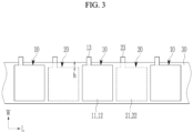
- FIG. 3 is a top plan view illustrating a state in which the electrode assembly illustrated in FIG. 2 is unfolded according to one or more embodiments
- FIG. 4 is a partially enlarged cross-sectional view of first and second electrodes illustrated in FIG. 3 according to one or more embodiments.
- the separator 30 may include a plurality of flat portions 31 and a plurality of bent portions 32 and 33.
- the flat portions 31 and the bent portions 32 and 33 may be alternately positioned one by one in a longitudinal direction of the separator 30 (direction L in FIG. 3 ).
- the bent portions 32 and 33 may include the first bent portion 32 positioned at one side (right) of the flat portion 31, and the second bent portion 33 positioned at the other side (left) of the flat portion 31.
- the first bent portions 32 and the second bent portions 33 may be alternately positioned one by one in the longitudinal direction (direction L) of the separator 30.
- the first electrode 10 and the second electrode 20 may be positioned between the two adjacent flat portions 31 among the plurality of flat portions 31.
- the first electrode 10 and the second electrode 20 may be positioned to adjoin different surfaces of the separator 30.
- the first electrode 10 is positioned to adjoin one surface (e.g., front surface) of the separator 30
- the second electrode 20 may be positioned to adjoin the opposite surface (e.g., rear surface) of the separator 30.
- the first electrode 10 may include a first substrate 11, first composite material layers 12 positioned on two opposite surfaces of the first substrate 11, and a first tab 13 extending toward one side (e.g., upward) from the first substrate 11.
- the first composite material layer 12 may not be positioned on the first tab 13.
- the second electrode 20 may include a second substrate 21, second composite material layers 22 positioned on two opposite surfaces of the second substrate 21, and a second tab 23 extending toward one side (e.g., upward) from the second substrate 21.
- the second composite material layer 22 is not positioned on the second tab 23.
- the first substrate 11 may be configured as a copper or nickel foil.
- the first composite material layer 12 may include graphite, a conductive material, a binder, and the like.
- the second substrate 21 may be configured as an aluminium foil.
- the second composite material layer 22 may include a transition metal oxide such as LiCoO 2 , LiNiO 2 , or LiMn 2 O 4 , a conductive material, a binder, and the like.
- the first electrode 10 may be referred to as a negative electrode, and the second electrode 20 may be referred to as a positive electrode.
- the separator 30 may include a polymer material such as polyethylene (PE) or polypropylene (PP) and may insulate the first electrode 10 and the second electrode 20 while allowing a movement of lithium ions.
- PE polyethylene
- PP polypropylene
- the first composite material layer 12 At the time of charging the rechargeable battery 100, lithium ions are introduced into the first composite material layer 12, and the first composite material layer 12 expands. At the time of discharging the rechargeable battery 100, lithium ions are discharged from the first composite material layer 12, and the first composite material layer 12 contracts. As the service life of the rechargeable battery 100 increases, the first composite material layer 12 may be degraded by a repeated change in volume. Therefore, in consideration of the degradation, the first electrode 10 may be configured to be larger than the second electrode 20.
- the first substrate 11 may have a larger height than the second substrate 21, and the first substrate 11 and the second substrate 21 may have a height difference of h. Therefore, the first electrode 10 may include a portion that does not overlap the adjacent second electrode 20.
- the plurality of first electrodes 10 may be manufactured by a process of forming the first composite material layers 12 on the two opposite surfaces of the first substrate having a long band shape by stripe coating, and then cutting the first substrate into unit substrates.
- the plurality of second electrodes 20 may be manufactured by a process of forming the second composite material layers 22 on the two opposite surfaces of the second substrate having a long band shape by stripe coating, and then cutting the second substrate into unit substrates.
- a non-uniform thickness may occur when the first composite material layers 12 and the second composite material layers 22 are formed by stripe coating.
- a thickness of the first composite material layer 12 may be smaller than a thickness of the first composite material layer 12 in another region.
- a thickness of the second composite material layer 22 may be smaller than a thickness of the second composite material layer 22 in another region.
- the first composite material layer 12 may have a larger thickness than the second composite material layer 22.
- a thickness difference between the regions of the first composite material layer 12 may be larger than a thickness difference between the regions of the second composite material layer 22. If the cell stack 40 is manufactured by stacking ten to twenty first electrodes 10 and ten to twenty second electrodes 20, the thickness differences of the composite material layers 12 and 22 are accumulated, which may cause a greater thickness difference.
- FIG. 5 is a cross-sectional view of the electrode assembly taken along line B-B in FIG. 1 according to one or more embodiments.
- the cell stack 40 includes a first part 41 having a first thickness t1, and a second part 42 having a second thickness t2 smaller than the first thickness t1.
- the second part 42 may correspond to an upper portion of the first substrate 11, which adjoins the first tab 13, and an upper portion of the second substrate 21, which adjoins the second tab 23, and occupies a smaller area in the cell stack 40 than the first part 41.
- the electrode assembly 120 includes correction sheets 50 positioned on the second part 42 of the cell stack 40 and configured to uniformize the thickness of the cell stack 40, and a pair of first fixing parts 61 attached to left and right edges of the cell stack 40.
- the pair of first fixing parts 61 each include a portion that overlaps the correction sheet 50.
- the first fixing part 61 is omitted from FIG. 2 .
- the electrode assembly 120 may further include a second fixing part 62 attached to a lower edge of the cell stack 40.
- the pair of first fixing parts 61 and the second fixing part 62 serve to maintain a constant shape and thickness of the cell stack 40.
- a size of the correction sheet 50 may be equal to a size of the second part 42.
- the correction sheet 50 may adjoin an upper edge of the cell stack 40, and a width of the correction sheet 50 may be equal to a width of the cell stack 40.
- the upper edge of the cell stack 40 may be referred to as a first edge, and the left and right edges may be referred to as second and third edges, and the lower edge may be referred to as a fourth edge.
- the correction sheet 50 may be attached to any one of the front and rear surfaces of the second part 42 or attached to both the front and rear surfaces. In both the cases, a sum of a thickness (second thickness t2) of the second part 42 and a thickness of the correction sheet 50 may be equal to a thickness (first thickness t1) of the first part 41. That is, the number of correction sheets 50 and the thickness of the correction sheet 50 may be appropriately selected in consideration of the thickness difference between the first part 41 and the second part 42.
- the correction sheet 50 may be configured as a polymer film having an adhesive layer, e.g., a film made of polyimide (PI) or polyethylene terephthalate (PET).
- the pair of first fixing parts 61 and the second fixing part 62 may each be configured as a polymer film having an adhesive layer.
- the correction sheet 50, the pair of first fixing parts 61, and the second fixing part 62 may be configured as polymer films made of the same material.
- the cell stack 40 may be pressed by a thermal press device.
- the cell stack 40 may be loaded into the thermal press device after the correction sheet 50 is attached to the second part 42.
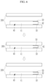
- FIG. 6 is a schematic view illustrating the thermal press device and the cell stack illustrated in FIG. 5 according to one or more embodiments.
- the cell stack 40 in which the correction sheet 50 is attached to the second part 42, may be loaded into a thermal press device 200, and the cell stack 40 may be compressed in a thickness direction by an operation of the thermal press device 200.
- the thermal press device 200 strongly joins the first electrode 10, the separator 30, and the second electrode 20 by pressing the cell stack 40. If the strongly joined state between the first electrode 10, the separator 30, and the second electrode 20 is maintained, the ionic conductivity may be improved during the charging/discharging process, which may ensure output characteristics of the rechargeable battery.
- the correction sheet 50 attached to the second part 42 transmits the pressure of the thermal press device 200 to the second part 42 so that the second part 42 is pressed by the same pressure as the first part 41. Therefore, both the first part 41 and the second part 42 of the cell stack 40 may receive uniform pressure, such that the joining forces between the first electrode 10, the separator 30, and the second electrode 20 may be increased, and the overall thickness may be uniformized.
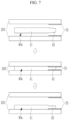
- FIG. 7 is a schematic view illustrating a thermal press device and a cell stack according to a comparative example (comparison with FIG. 6 ).
- the cell stack 40a of the comparative example may include the first part 41 and the second part 42, which are identical to those of FIG. 6 , but does not include the correction sheet.
- a protruding portion 70, which corresponds to the second part 42, may be positioned on a thermal press device 201 of the comparative example.
- the second part 42 of the cell stack 40a may be pressed by the protruding portion 70.
- the cell stack 40a may move during a process of disposing the cell stack 40a on the thermal press device 201 and a process of pressing the cell stack 40a by the thermal press device 201, which may cause a position dispersion. In this case, the uniform pressing on the cell stack 40a may deteriorate.
- the uniform pressing on the cell stack 40 is ensured even though a position dispersion of the cell stack 40 occurs during the process of disposing the cell stack 40 on the thermal press device 200 and the process of pressing the cell stack 40 by the thermal press device 200.
- the pressing method of FIG. 6 may exclude the protruding portion of the comparative example, which may simplify the configuration of the thermal press device 200.
- the pair of first fixing parts 61 and the second fixing part 62 may be attached to the cell stack 40 after the thermal press process.
- the pair of first fixing parts 61 may be positioned at the left and right edges of the cell stack 40 over the front, lateral, and rear surfaces of the cell stack 40.
- the second fixing part 62 may be positioned at the lower edge of the cell stack 40 over the front, lateral, and rear surfaces of the cell stack 40.
- the pair of first fixing parts 61 and the second fixing part 62 maintain a constant shape and thickness of the cell stack 40.
- the pair of first fixing parts 61 each includes a portion that overlaps the correction sheet 50. That is, the pair of first fixing parts 61 may overlap the correction sheet 50 while covering the left and right edges of the correction sheet 50. Therefore, the correction sheet 50 may be attached to the cell stack 40 by its own adhesive layer and overlap the first fixing part 61, thereby more securely fixing the position.
- the plurality of first tabs 13 may overlap one another and be integrally fixed by a method such as welding.
- the plurality of second tabs 23 may overlap one another and be integrally fixed by a method such as welding.
- a first lead tab 81 may be fixed to the plurality of first tabs 13, and a second lead tab 82 may be fixed to the plurality of second tabs 23.
- the first lead tab 81 may be a terminal (e.g., a negative electrode terminal) of the first electrode 10
- the second lead tab 82 may be a terminal (e.g., a positive electrode terminal) of the second electrode 20.
- Junction portions between the plurality of first tabs 13 and the first lead tab 81 and junction portions between the plurality of second tabs 23 and the second lead tab 82 may be surrounded by a sealing tape 83, and the junction portions surrounded by the sealing tape 83 may overlap the sealing portion 133 of the casing 130.
- the correction sheet 50 may uniformize the thickness of the electrode assembly 120 and increase the joining forces between the first electrode 10, the separator 30, and the second electrode 20 in the entire electrode assembly 120. Therefore, the increased joining forces between the electrodes 10 and 20 and the separator 30 of the rechargeable battery 100 may improve the output characteristics and output stability.
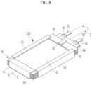
- FIG. 8 is a perspective view of an electrode assembly of a rechargeable battery according to one or more embodiments.
- FIG. 9 is a cross-sectional view of the electrode assembly taken along line C-C in FIG. 8 according to one or more embodiments
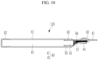
- FIG. 10 is a cross-sectional view of the electrode assembly taken along line D-D in FIG. 8 according to one or more embodiments.
- the rechargeable battery of FIG. 8 may be identical or similar in configuration to that in FIG. 1 , except for third and fourth fixing parts to be described below.
- the electrode assembly 120 may include a third fixing part 63.
- the third fixing part 63 may be attached to the upper edge of the cell stack 40 and may have a portion that overlaps the correction sheet 50.
- the third fixing part 63 may be provided between the plurality of first tabs 13 and the plurality of second tabs 23 and positioned at a predetermined distance from the plurality of first tabs 13 and the plurality of second tabs 23.
- the third fixing part 63 may be positioned over the outer surface of the correction sheet 50 fixed to the front surface of the cell stack 40, the lateral surface of the cell stack 40, and the outer surface of the correction sheet 50 attached to the rear surface of the cell stack 40.
- the third fixing part 63 may be configured as a polymer film having an adhesive layer and including a polymer film made of the same material as the correction sheet 50.
- the third fixing part 63 serves to maintain a constant shape and thickness of the cell stack 40 at the upper side of the cell stack 40.
- the electrode assembly 120 may further include a fourth fixing part 64.
- the fourth fixing part 64 simultaneously surrounds the plurality of first tabs 13 and the plurality of second tabs 23 and has a portion that overlaps the correction sheet 50 and the third fixing part 63.
- the fourth fixing part 64 may overlap a part of the upper side of the correction sheet 50 and a part of the upper side of the third fixing part 63.
- a horizontal width of the fourth fixing part 64 may be set to be smaller than a distance between the pair of first fixing parts 61.
- the fourth fixing part 64 may be configured as a polymer film having an adhesive layer and may include the same polymer film as the correction sheet 50 and the third fixing part 63.
- the fourth fixing part 64 may more assuredly fix the positions of the correction sheet 50 and the third fixing part 63 at the upper side of the cell stack 40.
- the fourth fixing part 64 may protect the plurality of first tabs 13 and the plurality of second tabs 23 at the time of thermally bonding the casing 130.
- Table 1 below shows a result of measuring thicknesses of electrode assemblies according to four examples and electrode assemblies according to the comparative example.
- a final thickness means a thickness of the electrode assembly after the electrode assembly and the casing are assembled and the formation process is completed.
- Table 1 Measurem ent position Example 1
- Example 2 Example 3
- Example 4 Comparati ve Example High (P1) 4.29 4.26 4.28 4.26 4.19 Thickness (mm) immediate ly after thermal press Medium (P2) 4.27 4.27 4.26 4.26 4.25 Low (P3) 4.28 4.29 4.27 4.27 4.25 Standard deviation (delta) 0.01 0.03 0.02 0.02 0.06 Final thickness (mm) High (P1) 4.404 4.359 4.396 4.379 4.318 Medium (P2) 4.417 4.398 4.422 4.413 4.410 Low (P3) 4.417 4.403 4.444 4.425 4.426 Standard deviation (delta) 0.043 0.044 0.048 0.108
- FIG. 11 is a schematic view illustrating the electrode assemblies according to Examples 1 to 4 in Table 1 above and the comparative example.
- the electrode assemblies 120A according to Examples 1 and 2 correspond to the electrode assembly illustrated in FIG. 1 and include the cell stack 40, the two correction sheets 50, the two first fixing parts 61, and the second fixing part 62.
- the two correction sheets 50 may be positioned on the front and rear surfaces of the second part 42.
- the two correction sheets 50 each have a thickness of 56 ⁇ m.
- the two correction sheets 50 each have a thickness of 30 ⁇ m.
- the electrode assemblies 120B according to Examples 3 and 4 correspond to the electrode assembly illustrated in FIG. 8 and include the cell stack 40, the two correction sheets 50, the two first fixing parts 61 and the second to fourth fixing parts 62, 63 and 64.
- the two correction sheets 50 may be positioned on the front and rear surfaces of the second part 42.
- the two correction sheets 50 each have a thickness of 56 ⁇ m.
- the two correction sheets 50 each have a thickness of 30 ⁇ m.
- An electrode assembly 220 according to the comparative example of FIG. 7 includes the cell stack 40, the two first fixing parts 61, the second fixing part 62, and the third fixing part 63.
- the measurement positions High (P1)/Medium (P2)/Low (P3) for measuring the thicknesses of the electrode assemblies 120A, 120B, and 220 may be positioned side by side in the vertical direction in FIG. 11 .
- the measurement position High (P1) may be one point on the second part 42, and the measurement position Low (P3) may be one point on the second fixing part 62 closer to the lower edge of the cell stack 40.
- the measurement position Medium (P2) may be positioned between P1 and P3 and may correspond to the first part 41.
- the present disclosure provides a rechargeable battery capable of uniformizing a thickness of an electrode assembly, increasing joining forces between a positive electrode, a separator, and a negative electrode in the entire electrode assembly, and improving output characteristics and output stability.
- the correction sheet may uniformize the thickness of the electrode assembly and increase the joining forces between the first electrode, the separator, and the second electrode in the entire electrode assembly. Therefore, output characteristics and output stability of the rechargeable battery may be improved by the increased joining forces between the electrodes and the separator.
Landscapes
- Chemical & Material Sciences (AREA)
- Chemical Kinetics & Catalysis (AREA)
- Electrochemistry (AREA)
- General Chemical & Material Sciences (AREA)
- Engineering & Computer Science (AREA)
- Manufacturing & Machinery (AREA)
- Secondary Cells (AREA)
Abstract
A rechargeable battery includes an electrode assembly and a casing configured to accommodate and seal the electrode assembly, wherein the electrode assembly includes a cell stack including a plurality of first electrodes and a plurality of second electrodes alternately stacked one by one with a separator interposed therebetween, the cell stack including a first part having a first thickness, and a second part having a second thickness smaller than the first thickness, a correction sheet positioned on the second part and configured to uniformize a thickness of the cell stack, and a pair of first fixing parts positioned over front, lateral, and rear surfaces of the cell stack and having a portion that overlaps the correction sheet.
Description
- Embodiments relate to a rechargeable battery, and more particularly, to a structure of a stacked electrode assembly.
- Rechargeable batteries, which are capable of being charged, are used for various purposes such as power sources for small-scale electronic devices, such as mobile phones and notebook computers, and power sources for driving motors of transportation means such as electric vehicles and hybrid vehicles. The rechargeable battery basically includes an electrode assembly and a casing for accommodating and sealing the electrode assembly. The rechargeable batteries may be classified into a cylindrical battery, an angular battery, a pouch-type battery, and the like depending on external shapes of the rechargeable batteries.
- The electrode assembly may be configured by alternately stacking a plurality of positive electrodes and a plurality of negative electrodes one by one with separators interposed therebetween. The positive electrode and the negative electrode may each include a substrate and composite material layers positioned on two opposite surfaces of the substrate. A non-uniform thickness may occur during a process of manufacturing the composite material layer. The non-uniform thickness of the composite material layer causes a non-uniform thickness of the electrode assembly. In addition, in a region of the electrode assembly in which a thickness of the composite material layer is insufficient, joining forces between the positive electrode, the separator, and the negative electrode are decreased, which may degrade output characteristics and output stability of the rechargeable battery.
- Embodiments include a rechargeable battery. The rechargeable battery includes an electrode assembly and a casing configured to accommodate and seal the electrode assembly, wherein the electrode assembly includes a cell stack including a plurality of first electrodes and a plurality of second electrodes alternately stacked one by one with a separator interposed therebetween, the cell stack including a first part having a first thickness, and a second part having a second thickness smaller than the first thickness. A correction sheet is positioned on the second part and uniformizes a thickness of the cell stack. A pair of first fixing parts is positioned over a front surface, a lateral surface and a rear surface of the cell stack, the pair of first fixing parts having a portion that overlaps the correction sheet.
- The correction sheet may include a pair of correction sheets respectively positioned on a front surface and a rear surface of the second part.
- Each of the pair of correction sheets may be configured as a polymer film having an adhesive layer.
- The cell stack may have a uniform thickness by being pressed by a thermal press device after the correction sheet is attached to the second part.
- The cell stack may include a first edge and second and third edges intersecting the first edge, a plurality of first tabs extending from the plurality of first electrodes and a plurality of second tabs extending from the plurality of second electrodes at the first edge, and the second part and the correction sheet may be positioned to adjoin the first edge.
- The second part and the correction sheet may each have a width equal to a width of the cell stack.
- The pair of first fixing parts may be positioned over the front surface, the lateral surface and the rear surface of the cell stack at the second and third edges and may overlap the correction sheet on at least one of the front surface and the rear surface of the cell stack.
- The cell stack may include a fourth edge parallel to the first edge and intersecting the second and third edges, and the electrode assembly may further include a second fixing part positioned over the front surface, the lateral surface and the rear surface of the cell stack at the fourth edge.
- The electrode assembly may further include a third fixing part positioned between the plurality of first tabs and the plurality of second tabs at the first edge, and the third fixing part may be positioned over the front surface, the lateral surface and the rear surface of the cell stack, the third fixing part including a portion that overlaps the correction sheet.
- The electrode assembly may further include a fourth fixing part configured to surround the plurality of first tabs and the plurality of second tabs.
- Embodiments include a rechargeable battery. The rechargeable battery includes an electrode assembly and a casing configured to accommodate and seal the electrode assembly. The electrode assembly includes a cell stack including a separator folded multiple times in a zigzag pattern, and a plurality of first electrodes and a plurality of second electrodes alternately stacked one by one with the separator interposed therebetween, the cell stack being divided into a first part and a second part having a smaller thickness than the first part. A pair of correction sheets provided on the second part and positioned on a front surface and a rear surface of the cell stack to uniformize a thickness of the cell stack and a plurality of fixing parts is attached to an edge of the cell stack over the front surface, a lateral surface and the rear surface of the cell stack, the plurality of fixing parts having a portion overlapping the pair of correction sheets while covering the pair of correction sheets from above.
- The cell stack may include a first edge, and second and third edges intersecting the first edge, a plurality of first tabs may extend from the plurality of first electrodes and a plurality of second tabs may extend from the plurality of second electrodes at the first edge, and the second part and the pair of correction sheets may be positioned to adjoin the first edge.
- The plurality of fixing parts may include a pair of first fixing parts, and the pair of first fixing parts may be attached to the pair of correction sheets and the cell stack at the second and third edges.
- The plurality of fixing parts may further include a third fixing part, and the third fixing part may be provided between the plurality of first tabs and the plurality of second tabs at the first edge and attached to the pair of correction sheets and the cell stack.
- At least some of the above and other features of the invention are set out in the claims.
- Features will become apparent to those of ordinary skill in the art by describing in detail embodiments with reference to the attached drawings, in which:
-
FIG. 1 is an exploded perspective view of a rechargeable battery according to one or more embodiments; -
FIG. 2 is a cross-sectional view of an electrode assembly taken along line A-A inFIG. 1 according to one or more embodiments; -
FIG. 3 is a top plan view illustrating a state in which the electrode assembly illustrated inFIG. 2 is unfolded according to one or more embodiments; -
FIG. 4 is a partially enlarged cross-sectional view of first and second electrodes illustrated inFIG. 3 according to one or more embodiments; -
FIG. 5 is a cross-sectional view of the electrode assembly taken along line B-B inFIG. 1 according to one or more embodiments; -
FIG. 6 is a schematic view illustrating a thermal press device and a cell stack illustrated inFIG. 5 according to one or more embodiments; -
FIG. 7 is a schematic view illustrating a thermal press device and a cell stack according to a comparative example (comparison withFIG. 6 ); -
FIG. 8 is a perspective view of an electrode assembly of a rechargeable battery according to one or more embodiments; -
FIG. 9 is a cross-sectional view of the electrode assembly taken along line C-C inFIG. 8 according to one or more embodiments; -
FIG. 10 is a cross-sectional view of the electrode assembly taken along line D-D inFIG. 8 according to one or more embodiments; and -
FIG. 11 is a schematic view illustrating electrode assemblies according to Examples 1 and 2 and the comparative example. - In the drawing figures, the dimensions of layers and regions may be exaggerated for clarity of illustration. It will also be understood that when a layer or element is referred to as being "on" another layer or substrate, it can be directly on the other layer or substrate, or intervening layers may also be present. Further, it will be understood that when a layer is referred to as being "under" another layer, it can be directly under, and one or more intervening layers may also be present. In addition, it will also be understood that when a layer is referred to as being "between" two layers, it can be the only layer between the two layers, or one or more intervening layers may also be present. Like reference numerals refer to like elements throughout.
- Hereinafter, embodiments of the present disclosure will be described in detail with reference to the accompanying drawings so that those with ordinary skill in the art to which the present disclosure pertains may easily carry out the embodiments. The present disclosure may be implemented in various different ways, and is not limited to the embodiments described herein.
-
FIG. 1 is an exploded perspective view of a rechargeable battery according to one or more embodiments, andFIG. 2 is a cross-sectional view of an electrode assembly taken along line A-A inFIG. 1 according to one or more embodiments. - With reference to
FIGS. 1 and2 , arechargeable battery 100 according to one or more embodiments includes anelectrode assembly 120 and acasing 130 configured to accommodate and seal theelectrode assembly 120 and an electrolyte.FIG. 1 illustrates a pouch-type casing 130. However, the type of casing is not limited to the illustrated example and may vary. - The
casing 130 may include alower casing 131 including anaccommodation portion 132 and a sealingportion 133, and a flatupper casing 135. Thelower casing 131 and theupper casing 135 may be integrally connected to each other. Theaccommodation portion 132 may be a concave space provided to accommodate theelectrode assembly 120. The sealingportion 133 may be positioned to surround theaccommodation portion 132. - After the
electrode assembly 120 is accommodated in theaccommodation portion 132, theupper casing 135 may be folded and may overlap thelower casing 131 and theelectrode assembly 120. Further, an edge of the sealingportion 133 and an edge of theupper casing 135 may be integrally joined by thermal bonding, such that theelectrode assembly 120 may be sealed. - The
casing 130 may include a metal sheet and a plurality of polymer sheets configured to cover inner and outer surfaces of the metal sheet. The metal sheet may be an aluminium sheet and may provide mechanical strength to thecasing 130. The polymer sheet may be any one of a polyethylene terephthalate (PET) sheet, a nylon sheet, and a PET-nylon composite sheet and serve to insulate and protect thecasing 130. - The
electrode assembly 120 includes acell stack 40. Thecell stack 40 includes a plurality offirst electrodes 10 and a plurality ofsecond electrodes 20 alternately stacked one by one with aseparator 30 interposed therebetween. Thecell stack 40 may include a plurality of separators or a single separator.FIG. 2 illustrates thesingle separator 30 as an example. Theseparator 30 may have a long band shape and be folded multiple times in a zigzag pattern. -
FIG. 3 is a top plan view illustrating a state in which the electrode assembly illustrated inFIG. 2 is unfolded according to one or more embodiments, andFIG. 4 is a partially enlarged cross-sectional view of first and second electrodes illustrated inFIG. 3 according to one or more embodiments. - With reference to
FIGS. 2 to 4 , theseparator 30 may include a plurality offlat portions 31 and a plurality ofbent portions flat portions 31 and thebent portions FIG. 3 ). Thebent portions bent portion 32 positioned at one side (right) of theflat portion 31, and the secondbent portion 33 positioned at the other side (left) of theflat portion 31. The firstbent portions 32 and the secondbent portions 33 may be alternately positioned one by one in the longitudinal direction (direction L) of theseparator 30. - The
first electrode 10 and thesecond electrode 20 may be positioned between the two adjacentflat portions 31 among the plurality offlat portions 31. In the unfolded state of theseparator 30, thefirst electrode 10 and thesecond electrode 20 may be positioned to adjoin different surfaces of theseparator 30. For example, when thefirst electrode 10 is positioned to adjoin one surface (e.g., front surface) of theseparator 30, thesecond electrode 20 may be positioned to adjoin the opposite surface (e.g., rear surface) of theseparator 30. - The
first electrode 10 may include afirst substrate 11, first composite material layers 12 positioned on two opposite surfaces of thefirst substrate 11, and afirst tab 13 extending toward one side (e.g., upward) from thefirst substrate 11. The firstcomposite material layer 12 may not be positioned on thefirst tab 13. Thesecond electrode 20 may include asecond substrate 21, second composite material layers 22 positioned on two opposite surfaces of thesecond substrate 21, and asecond tab 23 extending toward one side (e.g., upward) from thesecond substrate 21. The secondcomposite material layer 22 is not positioned on thesecond tab 23. - The
first substrate 11 may be configured as a copper or nickel foil. The firstcomposite material layer 12 may include graphite, a conductive material, a binder, and the like. Thesecond substrate 21 may be configured as an aluminium foil. The secondcomposite material layer 22 may include a transition metal oxide such as LiCoO2, LiNiO2, or LiMn2O4, a conductive material, a binder, and the like. Thefirst electrode 10 may be referred to as a negative electrode, and thesecond electrode 20 may be referred to as a positive electrode. - The
separator 30 may include a polymer material such as polyethylene (PE) or polypropylene (PP) and may insulate thefirst electrode 10 and thesecond electrode 20 while allowing a movement of lithium ions. - At the time of charging the
rechargeable battery 100, lithium ions are introduced into the firstcomposite material layer 12, and the firstcomposite material layer 12 expands. At the time of discharging therechargeable battery 100, lithium ions are discharged from the firstcomposite material layer 12, and the firstcomposite material layer 12 contracts. As the service life of therechargeable battery 100 increases, the firstcomposite material layer 12 may be degraded by a repeated change in volume. Therefore, in consideration of the degradation, thefirst electrode 10 may be configured to be larger than thesecond electrode 20. - For example, based on a width direction (direction W in
FIG. 3 ) of theseparator 30 inFIGS. 3 and4 , thefirst substrate 11 may have a larger height than thesecond substrate 21, and thefirst substrate 11 and thesecond substrate 21 may have a height difference of h. Therefore, thefirst electrode 10 may include a portion that does not overlap the adjacentsecond electrode 20. - The plurality of
first electrodes 10 may be manufactured by a process of forming the first composite material layers 12 on the two opposite surfaces of the first substrate having a long band shape by stripe coating, and then cutting the first substrate into unit substrates. In addition, the plurality ofsecond electrodes 20 may be manufactured by a process of forming the second composite material layers 22 on the two opposite surfaces of the second substrate having a long band shape by stripe coating, and then cutting the second substrate into unit substrates. - A non-uniform thickness may occur when the first composite material layers 12 and the second composite material layers 22 are formed by stripe coating. For example, in an upper region of the
first substrate 11 that adjoins thefirst tab 13, a thickness of the firstcomposite material layer 12 may be smaller than a thickness of the firstcomposite material layer 12 in another region. In an upper region of thesecond substrate 21 that adjoins thesecond tab 23, a thickness of the secondcomposite material layer 22 may be smaller than a thickness of the secondcomposite material layer 22 in another region. - The first
composite material layer 12 may have a larger thickness than the secondcomposite material layer 22. A thickness difference between the regions of the firstcomposite material layer 12 may be larger than a thickness difference between the regions of the secondcomposite material layer 22. If thecell stack 40 is manufactured by stacking ten to twentyfirst electrodes 10 and ten to twentysecond electrodes 20, the thickness differences of the composite material layers 12 and 22 are accumulated, which may cause a greater thickness difference. -
FIG. 5 is a cross-sectional view of the electrode assembly taken along line B-B inFIG. 1 according to one or more embodiments. - With reference to
FIGS. 1 and5 , thecell stack 40 includes afirst part 41 having a first thickness t1, and asecond part 42 having a second thickness t2 smaller than the first thickness t1. Thesecond part 42 may correspond to an upper portion of thefirst substrate 11, which adjoins thefirst tab 13, and an upper portion of thesecond substrate 21, which adjoins thesecond tab 23, and occupies a smaller area in thecell stack 40 than thefirst part 41. - The
electrode assembly 120 includescorrection sheets 50 positioned on thesecond part 42 of thecell stack 40 and configured to uniformize the thickness of thecell stack 40, and a pair of first fixingparts 61 attached to left and right edges of thecell stack 40. In this case, the pair of first fixingparts 61 each include a portion that overlaps thecorrection sheet 50. For convenience, the first fixingpart 61 is omitted fromFIG. 2 . - The
electrode assembly 120 may further include a second fixingpart 62 attached to a lower edge of thecell stack 40. The pair of first fixingparts 61 and the second fixingpart 62 serve to maintain a constant shape and thickness of thecell stack 40. - A size of the
correction sheet 50 may be equal to a size of thesecond part 42. Thecorrection sheet 50 may adjoin an upper edge of thecell stack 40, and a width of thecorrection sheet 50 may be equal to a width of thecell stack 40. The upper edge of thecell stack 40 may be referred to as a first edge, and the left and right edges may be referred to as second and third edges, and the lower edge may be referred to as a fourth edge. - The
correction sheet 50 may be attached to any one of the front and rear surfaces of thesecond part 42 or attached to both the front and rear surfaces. In both the cases, a sum of a thickness (second thickness t2) of thesecond part 42 and a thickness of thecorrection sheet 50 may be equal to a thickness (first thickness t1) of thefirst part 41. That is, the number ofcorrection sheets 50 and the thickness of thecorrection sheet 50 may be appropriately selected in consideration of the thickness difference between thefirst part 41 and thesecond part 42. - The
correction sheet 50 may be configured as a polymer film having an adhesive layer, e.g., a film made of polyimide (PI) or polyethylene terephthalate (PET). The pair of first fixingparts 61 and the second fixingpart 62 may each be configured as a polymer film having an adhesive layer. Thecorrection sheet 50, the pair of first fixingparts 61, and the second fixingpart 62 may be configured as polymer films made of the same material. - After the plurality of
first electrodes 10 and the plurality ofsecond electrodes 20 are alternately disposed one by one between theseparator 30 folded in a zigzag pattern, thecell stack 40 may be pressed by a thermal press device. Thecell stack 40 may be loaded into the thermal press device after thecorrection sheet 50 is attached to thesecond part 42. -
FIG. 6 is a schematic view illustrating the thermal press device and the cell stack illustrated inFIG. 5 according to one or more embodiments. - With reference to
FIGS. 2 and6 , thecell stack 40, in which thecorrection sheet 50 is attached to thesecond part 42, may be loaded into athermal press device 200, and thecell stack 40 may be compressed in a thickness direction by an operation of thethermal press device 200. Thethermal press device 200 strongly joins thefirst electrode 10, theseparator 30, and thesecond electrode 20 by pressing thecell stack 40. If the strongly joined state between thefirst electrode 10, theseparator 30, and thesecond electrode 20 is maintained, the ionic conductivity may be improved during the charging/discharging process, which may ensure output characteristics of the rechargeable battery. - The
correction sheet 50 attached to thesecond part 42 transmits the pressure of thethermal press device 200 to thesecond part 42 so that thesecond part 42 is pressed by the same pressure as thefirst part 41. Therefore, both thefirst part 41 and thesecond part 42 of thecell stack 40 may receive uniform pressure, such that the joining forces between thefirst electrode 10, theseparator 30, and thesecond electrode 20 may be increased, and the overall thickness may be uniformized. -
FIG. 7 is a schematic view illustrating a thermal press device and a cell stack according to a comparative example (comparison withFIG. 6 ). - With reference to
FIG. 7 , thecell stack 40a of the comparative example may include thefirst part 41 and thesecond part 42, which are identical to those ofFIG. 6 , but does not include the correction sheet. A protrudingportion 70, which corresponds to thesecond part 42, may be positioned on athermal press device 201 of the comparative example. - The
second part 42 of thecell stack 40a may be pressed by the protrudingportion 70. However, in the case of the pressing method of the comparative example, thecell stack 40a may move during a process of disposing thecell stack 40a on thethermal press device 201 and a process of pressing thecell stack 40a by thethermal press device 201, which may cause a position dispersion. In this case, the uniform pressing on thecell stack 40a may deteriorate. - With reference back to
FIG. 6 , because thecorrection sheet 50 is attached in advance to thesecond part 42, the uniform pressing on thecell stack 40 is ensured even though a position dispersion of thecell stack 40 occurs during the process of disposing thecell stack 40 on thethermal press device 200 and the process of pressing thecell stack 40 by thethermal press device 200. In addition, the pressing method ofFIG. 6 may exclude the protruding portion of the comparative example, which may simplify the configuration of thethermal press device 200. - With reference back to
FIGS. 1 and5 , the pair of first fixingparts 61 and the second fixingpart 62 may be attached to thecell stack 40 after the thermal press process. However, the present disclosure is not limited to that order. The pair of first fixingparts 61 may be positioned at the left and right edges of thecell stack 40 over the front, lateral, and rear surfaces of thecell stack 40. Thesecond fixing part 62 may be positioned at the lower edge of thecell stack 40 over the front, lateral, and rear surfaces of thecell stack 40. The pair of first fixingparts 61 and the second fixingpart 62 maintain a constant shape and thickness of thecell stack 40. - The pair of first fixing
parts 61 each includes a portion that overlaps thecorrection sheet 50. That is, the pair of first fixingparts 61 may overlap thecorrection sheet 50 while covering the left and right edges of thecorrection sheet 50. Therefore, thecorrection sheet 50 may be attached to thecell stack 40 by its own adhesive layer and overlap the first fixingpart 61, thereby more securely fixing the position. - With reference back to
FIG. 1 , the plurality offirst tabs 13 may overlap one another and be integrally fixed by a method such as welding. The plurality ofsecond tabs 23 may overlap one another and be integrally fixed by a method such as welding. Afirst lead tab 81 may be fixed to the plurality offirst tabs 13, and asecond lead tab 82 may be fixed to the plurality ofsecond tabs 23. - The
first lead tab 81 may be a terminal (e.g., a negative electrode terminal) of thefirst electrode 10, and thesecond lead tab 82 may be a terminal (e.g., a positive electrode terminal) of thesecond electrode 20. Junction portions between the plurality offirst tabs 13 and thefirst lead tab 81 and junction portions between the plurality ofsecond tabs 23 and thesecond lead tab 82 may be surrounded by a sealingtape 83, and the junction portions surrounded by the sealingtape 83 may overlap the sealingportion 133 of thecasing 130. - According to the
rechargeable battery 100 ofFIG. 1 , thecorrection sheet 50 may uniformize the thickness of theelectrode assembly 120 and increase the joining forces between thefirst electrode 10, theseparator 30, and thesecond electrode 20 in theentire electrode assembly 120. Therefore, the increased joining forces between theelectrodes separator 30 of therechargeable battery 100 may improve the output characteristics and output stability. -
FIG. 8 is a perspective view of an electrode assembly of a rechargeable battery according to one or more embodiments.FIG. 9 is a cross-sectional view of the electrode assembly taken along line C-C inFIG. 8 according to one or more embodiments, andFIG. 10 is a cross-sectional view of the electrode assembly taken along line D-D inFIG. 8 according to one or more embodiments. The rechargeable battery ofFIG. 8 may be identical or similar in configuration to that inFIG. 1 , except for third and fourth fixing parts to be described below. - With reference to
FIGS. 8 to 10 , theelectrode assembly 120 may include a third fixingpart 63. The third fixingpart 63 may be attached to the upper edge of thecell stack 40 and may have a portion that overlaps thecorrection sheet 50. The third fixingpart 63 may be provided between the plurality offirst tabs 13 and the plurality ofsecond tabs 23 and positioned at a predetermined distance from the plurality offirst tabs 13 and the plurality ofsecond tabs 23. - The third fixing
part 63 may be positioned over the outer surface of thecorrection sheet 50 fixed to the front surface of thecell stack 40, the lateral surface of thecell stack 40, and the outer surface of thecorrection sheet 50 attached to the rear surface of thecell stack 40. The third fixingpart 63 may be configured as a polymer film having an adhesive layer and including a polymer film made of the same material as thecorrection sheet 50. The third fixingpart 63 serves to maintain a constant shape and thickness of thecell stack 40 at the upper side of thecell stack 40. - The
electrode assembly 120 may further include a fourth fixingpart 64. The fourth fixingpart 64 simultaneously surrounds the plurality offirst tabs 13 and the plurality ofsecond tabs 23 and has a portion that overlaps thecorrection sheet 50 and the third fixingpart 63. The fourth fixingpart 64 may overlap a part of the upper side of thecorrection sheet 50 and a part of the upper side of the third fixingpart 63. A horizontal width of the fourth fixingpart 64 may be set to be smaller than a distance between the pair of first fixingparts 61. - The fourth fixing
part 64 may be configured as a polymer film having an adhesive layer and may include the same polymer film as thecorrection sheet 50 and the third fixingpart 63. The fourth fixingpart 64 may more assuredly fix the positions of thecorrection sheet 50 and the third fixingpart 63 at the upper side of thecell stack 40. The fourth fixingpart 64 may protect the plurality offirst tabs 13 and the plurality ofsecond tabs 23 at the time of thermally bonding thecasing 130. - Table 1 below shows a result of measuring thicknesses of electrode assemblies according to four examples and electrode assemblies according to the comparative example. In the table below, a final thickness means a thickness of the electrode assembly after the electrode assembly and the casing are assembled and the formation process is completed.
Table 1 Measurem ent position Example 1 Example 2 Example 3 Example 4 Comparati ve Example High (P1) 4.29 4.26 4.28 4.26 4.19 Thickness (mm) immediate ly after thermal press Medium (P2) 4.27 4.27 4.26 4.26 4.25 Low (P3) 4.28 4.29 4.27 4.27 4.25 Standard deviation (delta) 0.01 0.03 0.02 0.02 0.06 Final thickness (mm) High (P1) 4.404 4.359 4.396 4.379 4.318 Medium (P2) 4.417 4.398 4.422 4.413 4.410 Low (P3) 4.417 4.403 4.444 4.425 4.426 Standard deviation (delta) 0.043 0.044 0.048 0.046 0.108 -
FIG. 11 is a schematic view illustrating the electrode assemblies according to Examples 1 to 4 in Table 1 above and the comparative example. - With reference to
FIG. 11 , theelectrode assemblies 120A according to Examples 1 and 2 correspond to the electrode assembly illustrated inFIG. 1 and include thecell stack 40, the twocorrection sheets 50, the twofirst fixing parts 61, and the second fixingpart 62. The twocorrection sheets 50 may be positioned on the front and rear surfaces of thesecond part 42. In theelectrode assembly 120A according to Example 1, the twocorrection sheets 50 each have a thickness of 56 µm. In theelectrode assembly 120A according to Example 2, the twocorrection sheets 50 each have a thickness of 30 µm. - The
electrode assemblies 120B according to Examples 3 and 4 correspond to the electrode assembly illustrated inFIG. 8 and include thecell stack 40, the twocorrection sheets 50, the twofirst fixing parts 61 and the second to fourth fixingparts correction sheets 50 may be positioned on the front and rear surfaces of thesecond part 42. In theelectrode assembly 120B according to Example 3, the twocorrection sheets 50 each have a thickness of 56 µm. In theelectrode assembly 120B according to Example 4, the twocorrection sheets 50 each have a thickness of 30 µm. - An
electrode assembly 220 according to the comparative example ofFIG. 7 includes thecell stack 40, the twofirst fixing parts 61, the second fixingpart 62, and the third fixingpart 63. - The measurement positions High (P1)/Medium (P2)/Low (P3) for measuring the thicknesses of the
electrode assemblies FIG. 11 . The measurement position High (P1) may be one point on thesecond part 42, and the measurement position Low (P3) may be one point on the second fixingpart 62 closer to the lower edge of thecell stack 40. The measurement position Medium (P2) may be positioned between P1 and P3 and may correspond to thefirst part 41. - According to the result shown in Table 1, it can be ascertained that the thickness difference between the positions P1-P3 is reduced and the thickness uniformity is improved in the
electrode assemblies correction sheet 50 in comparison with theelectrode assembly 220 according to the comparative example. The improvement on the thickness uniformity of theelectrode assemblies - The present disclosure provides a rechargeable battery capable of uniformizing a thickness of an electrode assembly, increasing joining forces between a positive electrode, a separator, and a negative electrode in the entire electrode assembly, and improving output characteristics and output stability.
- In the rechargeable battery according to one or more embodiments, the correction sheet may uniformize the thickness of the electrode assembly and increase the joining forces between the first electrode, the separator, and the second electrode in the entire electrode assembly. Therefore, output characteristics and output stability of the rechargeable battery may be improved by the increased joining forces between the electrodes and the separator.
- While the embodiments of the present disclosure have been described above, the present disclosure is not limited thereto, and various modifications can be made and carried out within the scope of the claims, the detailed description and the accompanying drawings, and also fall within the scope of the present disclosure.
- Example embodiments have been disclosed herein, and although specific terms are employed, they are used and are to be interpreted in a generic and descriptive sense only and not for purpose of limitation. In some instances, as would be apparent to one of ordinary skill in the art as of the filing of the present application, features, characteristics, and/or elements described in connection with a particular embodiment may be used singly or in combination with features, characteristics, and/or elements described in connection with other embodiments unless otherwise specifically indicated. Accordingly, it will be understood by those of ordinary skill in the art that various changes in form and details may be made without departing from the scope of the present invention as set forth in the following claims.
Claims (14)
- A rechargeable battery comprising:an electrode assembly; anda casing configured to accommodate and seal the electrode assembly, wherein the electrode assembly includes:a cell stack including a plurality of first electrodes and a plurality of second electrodes alternately stacked one by one with a separator interposed therebetween, the cell stack including a first part having a first thickness, and a second part having a second thickness smaller than the first thickness;a correction sheet positioned on the second part and configured to uniformize a thickness of the cell stack; anda pair of first fixing parts positioned over a front surface, a lateral surface and a rear surface of the cell stack, the pair of first fixing parts having a portion that overlaps the correction sheet.
- The rechargeable battery as claimed in claim 1, wherein the correction sheet includes a pair of correction sheets respectively positioned on a front surface and a rear surface of the second part.
- The rechargeable battery as claimed in claim 2, wherein each of the pair of correction sheets is configured as a polymer film having an adhesive layer.
- The rechargeable battery as claimed in any one of claims 1 to 3, wherein the cell stack has a uniform thickness by being pressed by a thermal press device after the correction sheet is attached to the second part.
- The rechargeable battery as claimed in any one of claims 1 to 4, wherein:the cell stack includes a first edge and second and third edges intersecting the first edge,a plurality of first tabs extending from the plurality of first electrodes and a plurality of second tabs extending from the plurality of second electrodes at the first edge, andthe second part and the correction sheet are positioned to adjoin the first edge.
- The rechargeable battery as claimed in claim 5, wherein the second part and the correction sheet each have a width equal to a width of the cell stack.
- The rechargeable battery as claimed in claim 5 or claim 6, wherein the pair of first fixing parts is positioned over the front surface, the lateral surface and the rear surface of the cell stack at the second and third edges and overlaps the correction sheet on at least one of the front surface and the rear surface of the cell stack.
- The rechargeable battery as claimed in any one of claims 5 to 7, wherein:the cell stack includes a fourth edge parallel to the first edge and intersecting the second and third edges, andthe electrode assembly further includes a second fixing part positioned over the front surface, the lateral surface and the rear surface of the cell stack at the fourth edge.
- The rechargeable battery as claimed in any one of claims 5 to 8, wherein:the electrode assembly further includes a third fixing part positioned between the plurality of first tabs and the plurality of second tabs at the first edge, andthe third fixing part is positioned over the front surface, the lateral surface and the rear surface of the cell stack, the third fixing part including a portion that overlaps the correction sheet.
- The rechargeable battery as claimed in any one of claims 5 to 9, wherein the electrode assembly further includes a fourth fixing part configured to surround the plurality of first tabs and the plurality of second tabs.
- A rechargeable battery, comprising:an electrode assembly; anda casing configured to accommodate and seal the electrode assembly, wherein the electrode assembly includes:a cell stack including a separator folded multiple times in a zigzag pattern, and a plurality of first electrodes and a plurality of second electrodes alternately stacked one by one with the separator interposed therebetween, the cell stack being divided into a first part and a second part having a smaller thickness than the first part;a pair of correction sheets provided on the second part and positioned on a front surface and a rear surface of the cell stack to uniformize a thickness of the cell stack; anda plurality of fixing parts attached to an edge of the cell stack over the front surface, a lateral surface and the rear surface of the cell stack, the plurality of fixing parts having a portion overlapping the pair of correction sheets while covering the pair of correction sheets from above.
- The rechargeable battery as claimed in claim 11, wherein:the cell stack includes a first edge, and second and third edges intersecting the first edge,a plurality of first tabs extends from the plurality of first electrodes and a plurality of second tabs extends from the plurality of second electrodes at the first edge, andthe second part and the pair of correction sheets are positioned to adjoin the first edge.
- The rechargeable battery as claimed in claim 12, wherein:the plurality of fixing parts includes a pair of first fixing parts, andthe pair of first fixing parts is attached to the pair of correction sheets and the cell stack at the second and third edges.
- The rechargeable battery as claimed in claim 13, wherein:the plurality of fixing parts further includes a third fixing part, andthe third fixing part is provided between the plurality of first tabs and the plurality of second tabs at the first edge and attached to the pair of correction sheets and the cell stack.
Applications Claiming Priority (1)
| Application Number | Priority Date | Filing Date | Title |
|---|---|---|---|
| KR1020230130988A KR20250046919A (en) | 2023-09-27 | 2023-09-27 | Secondary battery |
Publications (1)
| Publication Number | Publication Date |
|---|---|
| EP4531191A1 true EP4531191A1 (en) | 2025-04-02 |
Family
ID=92043181
Family Applications (1)
| Application Number | Title | Priority Date | Filing Date |
|---|---|---|---|
| EP24190846.6A Pending EP4531191A1 (en) | 2023-09-27 | 2024-07-25 | Rechargeable battery |
Country Status (4)
| Country | Link |
|---|---|
| US (1) | US20250105415A1 (en) |
| EP (1) | EP4531191A1 (en) |
| KR (1) | KR20250046919A (en) |
| CN (1) | CN119725663A (en) |
Cited By (1)
| Publication number | Priority date | Publication date | Assignee | Title |
|---|---|---|---|---|
| EP4685897A3 (en) * | 2024-07-22 | 2026-04-08 | SK On Co., Ltd. | Battery cell, manufacturing method of battery cell, and battery module |
Citations (4)
| Publication number | Priority date | Publication date | Assignee | Title |
|---|---|---|---|---|
| US20170324071A1 (en) * | 2014-11-28 | 2017-11-09 | Kabushiki Kaisha Toyota Jidoshokki | Power storage apparatus |
| JP2018137066A (en) * | 2017-02-20 | 2018-08-30 | 株式会社豊田自動織機 | Electrode assembly, power storage device and manufacturing method of electrode assembly |
| JP6394867B2 (en) * | 2014-07-30 | 2018-09-26 | 株式会社豊田自動織機 | Power storage device |
| WO2023043196A1 (en) * | 2021-09-14 | 2023-03-23 | 주식회사 엘지에너지솔루션 | Electrode assembly, secondary battery comprising same, secondary battery manufacturing method for manufacturing same, and secondary battery manufacturing device used therein |
-
2023
- 2023-09-27 KR KR1020230130988A patent/KR20250046919A/en active Pending
-
2024
- 2024-06-14 US US18/743,565 patent/US20250105415A1/en active Pending
- 2024-07-25 EP EP24190846.6A patent/EP4531191A1/en active Pending
- 2024-07-25 CN CN202411003260.4A patent/CN119725663A/en active Pending
Patent Citations (4)
| Publication number | Priority date | Publication date | Assignee | Title |
|---|---|---|---|---|
| JP6394867B2 (en) * | 2014-07-30 | 2018-09-26 | 株式会社豊田自動織機 | Power storage device |
| US20170324071A1 (en) * | 2014-11-28 | 2017-11-09 | Kabushiki Kaisha Toyota Jidoshokki | Power storage apparatus |
| JP2018137066A (en) * | 2017-02-20 | 2018-08-30 | 株式会社豊田自動織機 | Electrode assembly, power storage device and manufacturing method of electrode assembly |
| WO2023043196A1 (en) * | 2021-09-14 | 2023-03-23 | 주식회사 엘지에너지솔루션 | Electrode assembly, secondary battery comprising same, secondary battery manufacturing method for manufacturing same, and secondary battery manufacturing device used therein |
Cited By (1)
| Publication number | Priority date | Publication date | Assignee | Title |
|---|---|---|---|---|
| EP4685897A3 (en) * | 2024-07-22 | 2026-04-08 | SK On Co., Ltd. | Battery cell, manufacturing method of battery cell, and battery module |
Also Published As
| Publication number | Publication date |
|---|---|
| CN119725663A (en) | 2025-03-28 |
| US20250105415A1 (en) | 2025-03-27 |
| KR20250046919A (en) | 2025-04-03 |
Similar Documents
| Publication | Publication Date | Title |
|---|---|---|
| US9741974B2 (en) | Battery cell having round corner | |
| KR102303828B1 (en) | Flexible electrochemical device including electrode assemblies electrically connected to each other | |
| KR101526457B1 (en) | Electrode Having Round Corner | |
| KR102689862B1 (en) | Secondary battery | |
| US8703342B2 (en) | Electrode assembly, rechargeable battery including the same, and method of manufacturing an electrode thereof | |
| US20110076544A1 (en) | Stack type battery | |
| US12614793B2 (en) | Battery cell and battery cell manufacturing apparatus for manufacturing the same | |
| KR20180032083A (en) | Rechageable battery | |
| EP3211688B1 (en) | Rechargeable battery | |
| US20150287966A1 (en) | Electrode assembly and secondary battery having the same | |
| US20240283003A1 (en) | Electrode Assembly and Battery Cell Including the Same | |
| EP3975306A1 (en) | Secondary battery | |
| EP4531191A1 (en) | Rechargeable battery | |
| KR102278445B1 (en) | Electrode assembly, and rechargeable battery | |
| US9484560B2 (en) | Electric device having a round corner and including a secondary battery | |
| KR20210122106A (en) | Stack of battery cells and method for assembling the same, battery module and vehicle | |
| US20230198106A1 (en) | Battery Cell Including Electrode Tab Having Stress Relief Portion | |
| KR20230082954A (en) | Secondary battery | |
| US20250087834A1 (en) | Electrode assembly and rechargeable battery including the same | |
| US20260058240A1 (en) | Pouch-type secondary batteries, press devices thereof, and manufacturing methods thereof | |
| EP4531175A1 (en) | Secondary battery | |
| EP4131589B1 (en) | Secondary battery manufacturing method | |
| US20250070325A1 (en) | Rechargeable battery and manufacturing method thereof | |
| US20250167275A1 (en) | Taping device for secondary battery and secondary battery manufactured using the same | |
| US20230268621A1 (en) | Rechargeable battery |
Legal Events
| Date | Code | Title | Description |
|---|---|---|---|
| PUAI | Public reference made under article 153(3) epc to a published international application that has entered the european phase |
Free format text: ORIGINAL CODE: 0009012 |
|
| STAA | Information on the status of an ep patent application or granted ep patent |
Free format text: STATUS: REQUEST FOR EXAMINATION WAS MADE |
|
| 17P | Request for examination filed |
Effective date: 20240725 |
|
| AK | Designated contracting states |
Kind code of ref document: A1 Designated state(s): AL AT BE BG CH CY CZ DE DK EE ES FI FR GB GR HR HU IE IS IT LI LT LU LV MC ME MK MT NL NO PL PT RO RS SE SI SK SM TR |