EP4531186A1 - Secondary battery and secondary battery module including same - Google Patents
Secondary battery and secondary battery module including same Download PDFInfo
- Publication number
- EP4531186A1 EP4531186A1 EP23839886.1A EP23839886A EP4531186A1 EP 4531186 A1 EP4531186 A1 EP 4531186A1 EP 23839886 A EP23839886 A EP 23839886A EP 4531186 A1 EP4531186 A1 EP 4531186A1
- Authority
- EP
- European Patent Office
- Prior art keywords
- battery case
- secondary battery
- edge
- exposing part
- exposing
- Prior art date
- Legal status (The legal status is an assumption and is not a legal conclusion. Google has not performed a legal analysis and makes no representation as to the accuracy of the status listed.)
- Pending
Links
Images




Classifications
-
- H—ELECTRICITY
- H01—ELECTRIC ELEMENTS
- H01M—PROCESSES OR MEANS, e.g. BATTERIES, FOR THE DIRECT CONVERSION OF CHEMICAL ENERGY INTO ELECTRICAL ENERGY
- H01M50/00—Constructional details or processes of manufacture of the non-active parts of electrochemical cells other than fuel cells, e.g. hybrid cells
- H01M50/10—Primary casings; Jackets or wrappings
- H01M50/102—Primary casings; Jackets or wrappings characterised by their shape or physical structure
- H01M50/105—Pouches or flexible bags
-
- H—ELECTRICITY
- H01—ELECTRIC ELEMENTS
- H01M—PROCESSES OR MEANS, e.g. BATTERIES, FOR THE DIRECT CONVERSION OF CHEMICAL ENERGY INTO ELECTRICAL ENERGY
- H01M50/00—Constructional details or processes of manufacture of the non-active parts of electrochemical cells other than fuel cells, e.g. hybrid cells
- H01M50/10—Primary casings; Jackets or wrappings
- H01M50/183—Sealing members
- H01M50/184—Sealing members characterised by their shape or structure
-
- H—ELECTRICITY
- H01—ELECTRIC ELEMENTS
- H01M—PROCESSES OR MEANS, e.g. BATTERIES, FOR THE DIRECT CONVERSION OF CHEMICAL ENERGY INTO ELECTRICAL ENERGY
- H01M50/00—Constructional details or processes of manufacture of the non-active parts of electrochemical cells other than fuel cells, e.g. hybrid cells
- H01M50/10—Primary casings; Jackets or wrappings
- H01M50/183—Sealing members
- H01M50/186—Sealing members characterised by the disposition of the sealing members
-
- H—ELECTRICITY
- H01—ELECTRIC ELEMENTS
- H01M—PROCESSES OR MEANS, e.g. BATTERIES, FOR THE DIRECT CONVERSION OF CHEMICAL ENERGY INTO ELECTRICAL ENERGY
- H01M50/00—Constructional details or processes of manufacture of the non-active parts of electrochemical cells other than fuel cells, e.g. hybrid cells
- H01M50/20—Mountings; Secondary casings or frames; Racks, modules or packs; Suspension devices; Shock absorbers; Transport or carrying devices; Holders
- H01M50/204—Racks, modules or packs for multiple batteries or multiple cells
- H01M50/207—Racks, modules or packs for multiple batteries or multiple cells characterised by their shape
- H01M50/211—Racks, modules or packs for multiple batteries or multiple cells characterised by their shape adapted for pouch cells
-
- H—ELECTRICITY
- H01—ELECTRIC ELEMENTS
- H01M—PROCESSES OR MEANS, e.g. BATTERIES, FOR THE DIRECT CONVERSION OF CHEMICAL ENERGY INTO ELECTRICAL ENERGY
- H01M50/00—Constructional details or processes of manufacture of the non-active parts of electrochemical cells other than fuel cells, e.g. hybrid cells
- H01M50/30—Arrangements for facilitating escape of gases
- H01M50/342—Non-re-sealable arrangements
-
- H—ELECTRICITY
- H01—ELECTRIC ELEMENTS
- H01M—PROCESSES OR MEANS, e.g. BATTERIES, FOR THE DIRECT CONVERSION OF CHEMICAL ENERGY INTO ELECTRICAL ENERGY
- H01M50/00—Constructional details or processes of manufacture of the non-active parts of electrochemical cells other than fuel cells, e.g. hybrid cells
- H01M50/30—Arrangements for facilitating escape of gases
- H01M50/394—Gas-pervious parts or elements
-
- Y—GENERAL TAGGING OF NEW TECHNOLOGICAL DEVELOPMENTS; GENERAL TAGGING OF CROSS-SECTIONAL TECHNOLOGIES SPANNING OVER SEVERAL SECTIONS OF THE IPC; TECHNICAL SUBJECTS COVERED BY FORMER USPC CROSS-REFERENCE ART COLLECTIONS [XRACs] AND DIGESTS
- Y02—TECHNOLOGIES OR APPLICATIONS FOR MITIGATION OR ADAPTATION AGAINST CLIMATE CHANGE
- Y02E—REDUCTION OF GREENHOUSE GAS [GHG] EMISSIONS, RELATED TO ENERGY GENERATION, TRANSMISSION OR DISTRIBUTION
- Y02E60/00—Enabling technologies; Technologies with a potential or indirect contribution to GHG emissions mitigation
- Y02E60/10—Energy storage using batteries
Definitions
- the present invention relates to a secondary battery and a secondary battery module including the same, and more particularly, to a secondary battery including an electrode assembly and a battery case accommodating the electrode assembly and a secondary battery module including the same.
- one of the most spotlighted secondary batteries may be lithium secondary batteries, which are capable of being classified into can type, prismatic type, and pouch-type according to their shapes of exterior materials.
- the pouch-type secondary batteries are being widely used in medium and large-sized battery modules because of their high energy density and easy stacking.
- the pouch-type secondary battery may have a structure in which an electrode assembly is accommodated in a pouch-type battery case, and edges of the battery case are sealed.
- the secondary battery is ignited, a temperature of the secondary battery increases, and an electrolyte is evaporated inside the battery case to generate a gas, the gas may be ejected through a weakly sealed portion of the battery case without a certain path.
- the present invention has been invented to solve the above problems, and an object of the present invention is to provide a secondary battery that is capable of minimizing a risk of ignition by inducing a gas within a battery case so that the gas is discharged to a designated position in the event of an emergency situation such as ignition of the secondary battery, and a secondary battery module including the same.
- a secondary battery according to the present invention may include: an electrode assembly; and a battery case in which the electrode assembly is accommodated and of which an edge is sealed, wherein the battery case may include: at least one folding part folded so that a distal end of a portion of the edge of the battery case is hidden inward; and at least one exposing part through which a distal end of the other portion of the edge of the battery case is exposed to the outside.
- the sealing of the exposing part may be released to discharge a gas within the battery case.
- the folding part may be folded at least two times in one direction.
- the exposing part may be folded at least one time so that the distal end of the edge is exposed to the outside.
- the exposing part may be folded in a direction opposite to the folding part.
- the exposing part may be folded less times than the folding part.
- a gap between inner surfaces of the exposing part, which face each other, may be greater than that between inner surfaces of the folding part, which face each other.
- the secondary battery may further include an electrode lead protruding from one edge of the battery case.
- the exposing part may be disposed on the other edge of the battery case.
- the folding part may be disposed on the other edge of the battery case.
- the exposing part may be disposed adjacent to the folding part.
- the exposing part may be provided in plurality, which are spaced apart from each other in a longitudinal direction of the battery case, and the exposing part may be disposed between the plurality of folding parts.
- the secondary battery may further include a membrane part folded so that both ends thereof are connected to the exposing part to surround the distal end of the exposing part.
- the membrane part When a pressure inside the battery case increases above a predetermined pressure to release the sealing of the exposing part, the membrane part may be unfolded in a state in which both ends of the membrane part are connected to an outer surface of the exposing part.
- the membrane part may be made of a porous material.
- a secondary battery module may include: a plurality of secondary batteries arranged in one direction; and a housing configured to accommodate the plurality of secondary batteries.
- Each of the secondary batteries may include: an electrode assembly; and a battery case in which the electrode assembly is accommodated and of which an edge is sealed, wherein the battery case may include: at least one folding part folded so that a distal end of a portion of the edge of the battery case is hidden inward; and at least one exposing part through which a distal end of the other portion of the edge of the battery case is exposed to the outside.
- the present invention may have the effect of minimizing the risk of the ignition by inducting the gas generated inside the battery case so that the gas is discharged to the designated position by providing the exposing part, of which the distal end is exposed to the outside, at the edge of the battery case.
- the present invention may have the effect of preventing the external moisture and foreign substances from being introduced into the battery case while discharging the gas within the battery case by further including the membrane part connected to the exposing part.
- the present invention may have the effect in that, in the secondary battery module including the plurality of secondary batteries, the exposing part, of which the distal end is exposed to the outside, is provided at the edge of the battery case of the secondary battery so that the gas is discharged to the designated position to minimize the risk of the ignition, thereby suppressing and delaying the thermal runaway propagation between the secondary batteries inside the secondary module.
- a secondary battery 100 may include an electrode assembly 110 and a battery case 120 in which the electrode assembly 110 is accommodated and of which an edge is sealed.
- the battery case 120 may include at least one folding part 121, which is folded so that a distal end of a portion of the edge of the battery case 120 is hidden inward, and at least one exposing part 122 through which a distal end of the other portion of the edge of the battery case 120 is exposed outward.
- the exposing part 122 may be configured so that when an internal pressure of the battery case 120 is higher than a predetermined pressure, the sealing is released so that a gas inside the battery case 120 is discharged.
- the electrode assembly 110 may have various structures.
- the electrode assembly 110 may be provided by sequentially stacking an electrode and a separator.
- the electrode assembly 110 may have a structure in which positive electrode collector/positive electrode active material layer/separator/negative electrode active material layer/negative electrode collector are sequentially stacked so that the positive electrode active material layer disposed one surface of the separator faces the negative electrode active material layer disposed on the other surface of the separator.
- the type of electrode assembly 110 is not limited thereto, and also, it is also possible to be configured as a jelly roll-type electrode assembly.
- the electrode assembly 110 is accommodated inside the battery case 120 and is represented by a dotted line in the drawing.
- the battery case 120 in which the electrode assembly 110 is accommodated may be configured so that an edge thereof is sealed and may have various structures.
- the battery case 120 may be provided as two sheets on upper and lower sides of the electrode assembly 110.
- a portion of the sheet may be formed concavely to form an empty space so that the electrode assembly 110 is accommodated.
- An electrolyte together with the electrode assembly 110 may be accommodated in the empty space.
- the battery case 120 may have a structure with the sealed edge. This is done for preventing the electrode assembly 110 accommodated in the battery case 120 from being damaged due to exposure to external moisture and air.
- the edge of the battery case 120 may be sealed using a method such as thermal fusion.
- the edge of the battery case 120 may be referred to as a terrace part or a sealing part.
- the secondary battery 100 according to the present invention may be provided so that the edge of the battery case 120 is folded to reduce a volume of the secondary battery 100 or improve sealing force of the battery case 120, thereby improving energy density.
- the edge of the battery case 120 may be folded in a direction of an arrow in an unfolded state.
- the edge of the battery case 120 may be provided in the folded state.
- At least one exposing part 122 and a folding part 121 may be provided at the edge of the battery case 120 to discharge the gas to a designated position.
- the battery case 120 may include at least one folding part 121, which is folded so that a distal end of a portion of the edge of the battery case 120 is hidden inward, and at least one exposing part 122 through which a distal end of the other portion of the edge of the battery case 120 is exposed outward.
- the gas when a predetermined amount of gas is generated inside the battery case 120, the gas may be preferentially discharged from the exposing part 122, which is relatively easier to discharge the gas than the folding part 121.
- a user may discharge the gas to the designated position by selectively disposing the exposing part 122 on the battery case 120 to minimize a risk due to the ignition of the secondary battery 100.
- the folding part 121 may be configured to be folded so that the distal end of the edge of the battery case 120 is hidden inward and may have various structures.
- the folding part 121 may be provided by folding a portion of the edge of the battery case 120 as illustrated in FIGS. 3 and 4 . That is, the distal end of the portion of the edge of the battery case 120 may be a distal end 121a of the folding part 121. The distal end 121a of the folding part 121 may be hidden by inner surfaces of the folding part 121, which face each other.
- the folding part 121 may have a structure in which the gas is relatively more difficult to be discharged than the exposing part 122 in which the distal end 122a is exposed to the outside because the distal end 121a, through which the gas is discharged to the outside, is hidden inward and thus may be understood as a configuration that induces the discharge of the gas to the exposing part 122.
- the folding part 121 may have a structure in which the external moisture or air are relatively more difficult to be introduced because the distal end 121a is hidden inward and may be understood as a configuration that improves the sealing force of the battery case 120.
- the above-described folding part 121 may have any structure as long as the distal end 121a is hidden inward.
- the folding part 121 may have a structure that is folded at least twice or more in one direction so that the distal end portion 121a is wrapped inward at the edge of the battery case 120.
- the inner surfaces of the folding part 121 may be in contact with or be adjacent to each other to prevent the movement of the gas as much as possible.
- the present invention may include an exposing part 122 through which the seal is released, and the gas inside the battery case 120 is discharged when an internal pressure of the battery case 120 is higher than a predetermined pressure.
- the exposing part 122 may be provided by folding a portion of the edge of the battery case 120 as illustrated in FIGS. 3 and 5 . That is, the distal end of the other portion of the edge of the battery case 120 may be a distal end 122a of the exposing part 122. The distal end 122a of the exposing part 122 may be exposed to the outside.
- the exposing part 122 may have a structure in which the gas is relatively easily discharged when compared to the folding part 121, of which the distal end is hidden inward, because the distal end 122a, through which the gas is discharged to the outside, is exposed to the outside, and thus, the exposing part 122 may be understood as a configuration that operates preferentially rather than the above-described folding part 121 when the gas is generated in the battery case 120 so as to be used a gas discharge passage.
- the exposing part 122 may have any structure as long as the distal end 122a is exposed to the outside.
- the exposing part 122 may have a structure that is folded at least once so that the distal end 122a is exposed to the outside.
- the exposing part 122 may be folded in a direction opposite to the folding part 121.
- the exposing part 122 may be folded less times than the folding part 121.
- a gap g2 between inner surfaces facing each other in the exposing part 122 may be larger than a gap g1 between the inner surfaces facing each other in the folding part 121.
- Each of the gaps g1 and g2 may mean an average gap.
- the gas may be discharged more smoothly and preferentially through the exposing part 122.
- this exposing part 122 may be maintained in the sealed state when no gas is generated inside the battery case 120, or when the gas pressure inside the battery case 120 is less than the predetermined pressure.
- the sealing of the exposing part 122 may be released to induce the discharge of the gas, and thus, the internal pressure of the battery case 120 may be reduced.
- the exposing part 122 may be disposed in various manner in the battery case 120.
- the secondary battery 100 according to the present invention may further include an electrode lead 130 protruding from at least one end of the battery case 120.
- the exposing part 122 is disposed at a position that is far away from the electrode lead 130.
- the electrode lead 130 is electrically connected to the electrode assembly 110 inside the battery case 120 and the external electric device or secondary battery 100, this is because a spark occurs to cause rapid ignition when the gas discharged from the exposing part 122 is discharged at a position adjacent to the electrode lead 130.
- the exposing part 122 may be preferably disposed at the other edge of the battery case 120.
- the folding part 121 may also be disposed at another edge of the battery case 120.
- the electrode lead 130 may be disposed on a short side of the battery case 120, and the folding part 121 and the exposing part 122 may be disposed on a long side of the battery case 120.
- the exposing part 122 may be disposed adjacent to the folding part 121.
- the exposing part 122 may be disposed between the plurality of folding parts 121.
- the exposing part 122 described above may be provided in various numbers and positions on the battery case 120 in consideration of the amount of gas generated inside the battery case 120.
- the exposing part 122 may be provided as one part and disposed at a central portion of the edge of the battery case 120, as illustrated in FIG. 7 .
- the exposing part 122 may be provided in plurality as illustrated in FIG. 8 and may be provided in plurality spaced apart from each other in the longitudinal direction of the battery case 120 (X direction based on FIG. 8 ). In this case, the plurality of exposing parts 122 may be alternately disposed with the plurality of folding parts 121.
- the secondary battery 100 according to the present invention may further include a membrane part 140 that is folded to surround the distal end 122a of the exposing part 122.
- the membrane part 140 may be configured so that both ends thereof are connected to the exposing part 122 and folded to surround the distal end 122a of the exposing part 122, and may have various structures.
- the membrane part 140 may have a folded structure to surround the distal end of the exposing part 122.
- the membrane part 140 may be disposed so that the folded portion of the membrane part 140 is spaced a predetermined distance from the distal end 122a of the exposing part 122.
- both the ends of the membrane part 140 may be unfolded in a state of being connected to the outer surface of the exposing part 122.
- the membrane part 140 may be made of a porous material. Thus, when the sealing of the exposing part 122 is released, the gas inside the battery case 120 may be discharged to the outside, and simultaneously, the external moisture or foreign substances may be prevented from being introduced into the battery case 120.
- the membrane part 140 may be connected to the exposing part 122 in various manners.
- the membrane part 140 may be connected to the exposing part 122 by interposing an adhesive material 140a between an inner surface of the membrane part 140 and an outer surface of the exposing part 122.
- the adhesive material 140a may bond the membrane part 140 to the exposing part 122 through thermal fusion or the like.
- a secondary battery module may include: a plurality of secondary batteries 100 arranged in one direction; and a housing accommodating the plurality of the secondary batteries 100.
- Each of the secondary batteries 100 may include: an electrode assembly 110; and a battery case 120 in which an electrode assembly 110 is accommodated, and an edge thereof is sealed.
- the battery case 120 may include at least one folding part 121, which is folded so that a distal end of a portion of the edge of the battery case 120 is hidden inward, and at least one exposing part 122 through which a distal end of the other portion of the edge of the battery case 120 is exposed outward.
- the exposing part 122 may be configured so that when an internal pressure of the battery case 120 is higher than a predetermined pressure, the sealing is released so that a gas inside the battery case 120 is discharged.
- the plurality of secondary batteries 100 may be configured to be arranged in one direction in an accommodation space inside the housing and may have various configurations.
- folding part 121 and the exposing part 122 may be replaced with the above-described contents.
- the housing may be configured to accommodate the plurality of secondary batteries 100 and may have various configurations.
- the housing may have the accommodation space defined therein to accommodate the secondary batteries 100.
- a busbar electrically connected to an electrode lead 130 of the secondary battery 100 and a heat sink for discharging heat generated from the secondary battery 100 may be installed in the housing.
Landscapes
- Chemical & Material Sciences (AREA)
- Chemical Kinetics & Catalysis (AREA)
- Electrochemistry (AREA)
- General Chemical & Material Sciences (AREA)
- Gas Exhaust Devices For Batteries (AREA)
- Sealing Battery Cases Or Jackets (AREA)
- Battery Mounting, Suspending (AREA)
Abstract
Description
- The present application claims the benefit of the priority of
Korean Patent Application Nos. 10-2022-0085280, filed on July 11, 2022 10-2023-0087159, filed on July 05, 2023 - The present invention relates to a secondary battery and a secondary battery module including the same, and more particularly, to a secondary battery including an electrode assembly and a battery case accommodating the electrode assembly and a secondary battery module including the same.
- In recent, secondary batteries have attracted considerable attention as power sources for electric vehicles (EVs), hybrid electric vehicles (HEVs), and the like, which have been developed to solve limitations, such as air pollution, caused by existing gasoline and diesel vehicles that use fossil fuels.
- While one or two to three or four secondary batteries are used in a small mobile device, a battery module in which a plurality of secondary batteries are electrically connected to each other, or a battery pack in which a plurality of battery modules are electrically connected to each other is used due to needs for high power and large capacity in medium and large devices such as the electric vehicles.
- Among the currently commercialized secondary batteries, one of the most spotlighted secondary batteries may be lithium secondary batteries, which are capable of being classified into can type, prismatic type, and pouch-type according to their shapes of exterior materials. Among them, the pouch-type secondary batteries are being widely used in medium and large-sized battery modules because of their high energy density and easy stacking.
- As demands for secondary battery modules mounted on vehicles increase in recent years, customer's demands for stability are increasing. However, the customers are requiring to increase in energy density of the secondary battery within a limited space of the secondary battery module. In this case, there is a limitation in that risks of safety related to ignition and explosion of the secondary battery also increase together.
- The pouch-type secondary battery may have a structure in which an electrode assembly is accommodated in a pouch-type battery case, and edges of the battery case are sealed. However, when the secondary battery is ignited, a temperature of the secondary battery increases, and an electrolyte is evaporated inside the battery case to generate a gas, the gas may be ejected through a weakly sealed portion of the battery case without a certain path.
- Here, when the gas is ejected from a position adjacent to an electrode lead, a fatal problem may occur in which a spark causes rapid ignition of the secondary battery. As a result, it is necessary to develop a technology to solve the above problems.
- The present invention has been invented to solve the above problems, and an object of the present invention is to provide a secondary battery that is capable of minimizing a risk of ignition by inducing a gas within a battery case so that the gas is discharged to a designated position in the event of an emergency situation such as ignition of the secondary battery, and a secondary battery module including the same.
- A secondary battery according to the present invention may include: an electrode assembly; and a battery case in which the electrode assembly is accommodated and of which an edge is sealed, wherein the battery case may include: at least one folding part folded so that a distal end of a portion of the edge of the battery case is hidden inward; and at least one exposing part through which a distal end of the other portion of the edge of the battery case is exposed to the outside.
- When an internal pressure of the battery case is equal to or greater than a predetermined pressure, the sealing of the exposing part may be released to discharge a gas within the battery case.
- The folding part may be folded at least two times in one direction.
- The exposing part may be folded at least one time so that the distal end of the edge is exposed to the outside.
- The exposing part may be folded in a direction opposite to the folding part.
- The exposing part may be folded less times than the folding part.
- A gap between inner surfaces of the exposing part, which face each other, may be greater than that between inner surfaces of the folding part, which face each other.
- The secondary battery may further include an electrode lead protruding from one edge of the battery case. The exposing part may be disposed on the other edge of the battery case.
- The folding part may be disposed on the other edge of the battery case.
- The exposing part may be disposed adjacent to the folding part.
- The exposing part may be provided in plurality, which are spaced apart from each other in a longitudinal direction of the battery case, and the exposing part may be disposed between the plurality of folding parts.
- The secondary battery may further include a membrane part folded so that both ends thereof are connected to the exposing part to surround the distal end of the exposing part.
- When a pressure inside the battery case increases above a predetermined pressure to release the sealing of the exposing part, the membrane part may be unfolded in a state in which both ends of the membrane part are connected to an outer surface of the exposing part.
- The membrane part may be made of a porous material.
- A secondary battery module according to an embodiment of the present invention may include: a plurality of secondary batteries arranged in one direction; and a housing configured to accommodate the plurality of secondary batteries. Each of the secondary batteries may include: an electrode assembly; and a battery case in which the electrode assembly is accommodated and of which an edge is sealed, wherein the battery case may include: at least one folding part folded so that a distal end of a portion of the edge of the battery case is hidden inward; and at least one exposing part through which a distal end of the other portion of the edge of the battery case is exposed to the outside.
- The present invention may have the effect of minimizing the risk of the ignition by inducting the gas generated inside the battery case so that the gas is discharged to the designated position by providing the exposing part, of which the distal end is exposed to the outside, at the edge of the battery case.
- In addition, the present invention may have the effect of preventing the external moisture and foreign substances from being introduced into the battery case while discharging the gas within the battery case by further including the membrane part connected to the exposing part.
- In addition, the present invention may have the effect in that, in the secondary battery module including the plurality of secondary batteries, the exposing part, of which the distal end is exposed to the outside, is provided at the edge of the battery case of the secondary battery so that the gas is discharged to the designated position to minimize the risk of the ignition, thereby suppressing and delaying the thermal runaway propagation between the secondary batteries inside the secondary module.
-
-
FIG. 1 is a front view illustrating a configuration of a secondary battery before an edge of a battery case is folded to manufacture the secondary battery according to Embodiment 1 of the present invention. -
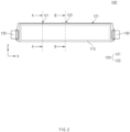
FIG. 2 is a front view of the secondary battery according to Embodiment 1 of the present invention. -
FIG. 3 is a detailed perspective view of an exposing part in the secondary battery ofFIG. 2 . -
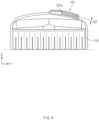
FIG. 4 is a cross-sectional view taken along line A-A inFIG. 2 . -
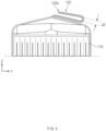
FIG. 5 is a cross-sectional view taken along line B-B inFIG. 2 so as to illustrate a state before a gas is discharged through the exposing part. -
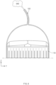
FIG. 6 is a cross-sectional view illustrating a state in which the gas is discharged through the exposing part ofFIG. 5 . -
FIG. 7 is a perspective view illustrating a state in which the gas is discharged through the exposing part in the secondary battery ofFIG. 2 . -
FIG. 8 is a front view of a secondary battery according to Embodiment 2 of the present invention. -
FIG. 9 is a perspective view illustrating a state in which a membrane part is connected to an exposing part in a secondary battery according to Embodiment 3 of the present invention. -
FIG. 10 is a cross-sectional view illustrating a state before a gas is discharged through the exposing part in the secondary battery ofFIG. 9 . -
FIG. 11 is a cross-sectional view illustrating a state in which the gas is discharged through the exposing part ofFIG. 10 . - Hereinafter, preferred embodiments of the present invention will be described in detail with reference to the accompanying drawings so that those of ordinary skill in the art can easily carry out the present invention. However, the present invention may be implemented in several different forms and is not limited or restricted by the following examples.
- In order to clearly explain the present invention, detailed descriptions of portions that are irrelevant to the description or related known technologies that may unnecessarily obscure the gist of the present invention have been omitted, and in the present specification, reference symbols are added to components in each drawing. In this case, the same or similar reference numerals are assigned to the same or similar elements throughout the specification.
- Also, terms or words used in this specification and claims should not be restrictively interpreted as ordinary meanings or dictionary-based meanings, but should be interpreted as meanings and concepts conforming to the scope of the present invention on the basis of the principle that an inventor can properly define the concept of a term to describe and explain his or her invention in the best ways.
- A
secondary battery 100 according to an embodiment of the present invention may include anelectrode assembly 110 and abattery case 120 in which theelectrode assembly 110 is accommodated and of which an edge is sealed. Thebattery case 120 may include at least one foldingpart 121, which is folded so that a distal end of a portion of the edge of thebattery case 120 is hidden inward, and at least one exposingpart 122 through which a distal end of the other portion of the edge of thebattery case 120 is exposed outward. - The
exposing part 122 may be configured so that when an internal pressure of thebattery case 120 is higher than a predetermined pressure, the sealing is released so that a gas inside thebattery case 120 is discharged. - In the present invention, the
electrode assembly 110 may have various structures. For example, theelectrode assembly 110 may be provided by sequentially stacking an electrode and a separator. In more detail, theelectrode assembly 110 may have a structure in which positive electrode collector/positive electrode active material layer/separator/negative electrode active material layer/negative electrode collector are sequentially stacked so that the positive electrode active material layer disposed one surface of the separator faces the negative electrode active material layer disposed on the other surface of the separator. However, the type ofelectrode assembly 110 is not limited thereto, and also, it is also possible to be configured as a jelly roll-type electrode assembly. - Note that the
electrode assembly 110 is accommodated inside thebattery case 120 and is represented by a dotted line in the drawing. - In addition, the
battery case 120 in which theelectrode assembly 110 is accommodated may be configured so that an edge thereof is sealed and may have various structures. - For example, the
battery case 120 may be provided as two sheets on upper and lower sides of theelectrode assembly 110. In addition, in at least one of the two sheets, a portion of the sheet may be formed concavely to form an empty space so that theelectrode assembly 110 is accommodated. An electrolyte together with theelectrode assembly 110 may be accommodated in the empty space. - The
battery case 120 may have a structure with the sealed edge. This is done for preventing theelectrode assembly 110 accommodated in thebattery case 120 from being damaged due to exposure to external moisture and air. In this case, the edge of thebattery case 120 may be sealed using a method such as thermal fusion. The edge of thebattery case 120 may be referred to as a terrace part or a sealing part. - The
secondary battery 100 according to the present invention may be provided so that the edge of thebattery case 120 is folded to reduce a volume of thesecondary battery 100 or improve sealing force of thebattery case 120, thereby improving energy density. - That is, as illustrated in
FIG. 1 , in the above-describedsecondary battery 100, the edge of thebattery case 120 may be folded in a direction of an arrow in an unfolded state. Thus, as illustrated inFIG. 2 , the edge of thebattery case 120 may be provided in the folded state. - Here, when a gas is generated in the
battery case 120 due to ignition of thesecondary battery 100, at least one exposingpart 122 and afolding part 121 may be provided at the edge of thebattery case 120 to discharge the gas to a designated position. - Specifically, as illustrated in
FIGS. 2 to 3 , thebattery case 120 may include at least onefolding part 121, which is folded so that a distal end of a portion of the edge of thebattery case 120 is hidden inward, and at least one exposingpart 122 through which a distal end of the other portion of the edge of thebattery case 120 is exposed outward. - Thus, when a predetermined amount of gas is generated inside the
battery case 120, the gas may be preferentially discharged from the exposingpart 122, which is relatively easier to discharge the gas than thefolding part 121. Thus, in thebattery case 120 having the above-described structure, a user may discharge the gas to the designated position by selectively disposing the exposingpart 122 on thebattery case 120 to minimize a risk due to the ignition of thesecondary battery 100. - Hereinafter, the structure of the
folding part 121 and the exposingpart 122 will be described in more detail. - First, the
folding part 121 may be configured to be folded so that the distal end of the edge of thebattery case 120 is hidden inward and may have various structures. - Specifically, the
folding part 121 may be provided by folding a portion of the edge of thebattery case 120 as illustrated inFIGS. 3 and4 . That is, the distal end of the portion of the edge of thebattery case 120 may be adistal end 121a of thefolding part 121. Thedistal end 121a of thefolding part 121 may be hidden by inner surfaces of thefolding part 121, which face each other. - The
folding part 121 may have a structure in which the gas is relatively more difficult to be discharged than the exposingpart 122 in which thedistal end 122a is exposed to the outside because thedistal end 121a, through which the gas is discharged to the outside, is hidden inward and thus may be understood as a configuration that induces the discharge of the gas to the exposingpart 122. - In addition, the
folding part 121 may have a structure in which the external moisture or air are relatively more difficult to be introduced because thedistal end 121a is hidden inward and may be understood as a configuration that improves the sealing force of thebattery case 120. - The above-described
folding part 121 may have any structure as long as thedistal end 121a is hidden inward. For example, thefolding part 121 may have a structure that is folded at least twice or more in one direction so that thedistal end portion 121a is wrapped inward at the edge of thebattery case 120. - In addition, even if the gas is introduced into the
folding part 121, the inner surfaces of thefolding part 121, which face each other, may be in contact with or be adjacent to each other to prevent the movement of the gas as much as possible. - The present invention may include an exposing
part 122 through which the seal is released, and the gas inside thebattery case 120 is discharged when an internal pressure of thebattery case 120 is higher than a predetermined pressure. - Specifically, the exposing
part 122 may be provided by folding a portion of the edge of thebattery case 120 as illustrated inFIGS. 3 and5 . That is, the distal end of the other portion of the edge of thebattery case 120 may be adistal end 122a of the exposingpart 122. Thedistal end 122a of the exposingpart 122 may be exposed to the outside. - Thus, the exposing
part 122 may have a structure in which the gas is relatively easily discharged when compared to thefolding part 121, of which the distal end is hidden inward, because thedistal end 122a, through which the gas is discharged to the outside, is exposed to the outside, and thus, the exposingpart 122 may be understood as a configuration that operates preferentially rather than the above-describedfolding part 121 when the gas is generated in thebattery case 120 so as to be used a gas discharge passage. - The exposing
part 122 may have any structure as long as thedistal end 122a is exposed to the outside. For example, the exposingpart 122 may have a structure that is folded at least once so that thedistal end 122a is exposed to the outside. Here, the exposingpart 122 may be folded in a direction opposite to thefolding part 121. In addition, the exposingpart 122 may be folded less times than thefolding part 121. - In addition, a gap g2 between inner surfaces facing each other in the exposing
part 122 may be larger than a gap g1 between the inner surfaces facing each other in thefolding part 121. Each of the gaps g1 and g2 may mean an average gap. - As a result, when the internal pressure of the
battery case 120 increases, the gas may be discharged more smoothly and preferentially through the exposingpart 122. - As illustrated in
FIG. 5 , this exposingpart 122 may be maintained in the sealed state when no gas is generated inside thebattery case 120, or when the gas pressure inside thebattery case 120 is less than the predetermined pressure. - In addition, as illustrated in
FIG. 6 , even when the gas is generated inside thebattery case 120, and the internal pressure of thebattery case 120 reaches a predetermined pressure or higher, the sealing of the exposingpart 122 may be released to induce the discharge of the gas, and thus, the internal pressure of thebattery case 120 may be reduced. - The exposing
part 122 may be disposed in various manner in thebattery case 120. - However, the
secondary battery 100 according to the present invention may further include anelectrode lead 130 protruding from at least one end of thebattery case 120. In this case, it is preferable that the exposingpart 122 is disposed at a position that is far away from theelectrode lead 130. - Since the
electrode lead 130 is electrically connected to theelectrode assembly 110 inside thebattery case 120 and the external electric device orsecondary battery 100, this is because a spark occurs to cause rapid ignition when the gas discharged from the exposingpart 122 is discharged at a position adjacent to theelectrode lead 130. - As illustrated in
FIGS. 6 and7 , when theelectrode lead 130 protrudes from one edge of thebattery case 120, the exposingpart 122 may be preferably disposed at the other edge of thebattery case 120. Thefolding part 121 may also be disposed at another edge of thebattery case 120. - In more detail, the
electrode lead 130 may be disposed on a short side of thebattery case 120, and thefolding part 121 and the exposingpart 122 may be disposed on a long side of thebattery case 120. - The exposing
part 122 may be disposed adjacent to thefolding part 121. Preferably, the exposingpart 122 may be disposed between the plurality offolding parts 121. - The exposing
part 122 described above may be provided in various numbers and positions on thebattery case 120 in consideration of the amount of gas generated inside thebattery case 120. - As an example, the exposing
part 122 may be provided as one part and disposed at a central portion of the edge of thebattery case 120, as illustrated inFIG. 7 . As another example, the exposingpart 122 may be provided in plurality as illustrated inFIG. 8 and may be provided in plurality spaced apart from each other in the longitudinal direction of the battery case 120 (X direction based onFIG. 8 ). In this case, the plurality of exposingparts 122 may be alternately disposed with the plurality offolding parts 121. - The
secondary battery 100 according to the present invention may further include amembrane part 140 that is folded to surround thedistal end 122a of the exposingpart 122. - Specifically, as illustrated in
FIGS. 9 to 11 , themembrane part 140 may be configured so that both ends thereof are connected to the exposingpart 122 and folded to surround thedistal end 122a of the exposingpart 122, and may have various structures. - In more detail, as illustrated in
FIG. 10 , when the exposingpart 122 is in a sealed state when the internal pressure of thebattery case 120 is less than the predetermined pressure, themembrane part 140 may have a folded structure to surround the distal end of the exposingpart 122. - Here, when the exposing
part 122 is in the sealed state so that both the ends of themembrane part 140 are maintained to be connected to the exposingpart 122 even when the sealing of the exposingpart 122 is released, themembrane part 140 may be disposed so that the folded portion of themembrane part 140 is spaced a predetermined distance from thedistal end 122a of the exposingpart 122. - As illustrated in
FIG. 11 , when the internal pressure of thebattery case 120 is higher than the predetermined pressure, and the sealing of the exposingpart 122 is released, both the ends of themembrane part 140 may be unfolded in a state of being connected to the outer surface of the exposingpart 122. - The
membrane part 140 may be made of a porous material. Thus, when the sealing of the exposingpart 122 is released, the gas inside thebattery case 120 may be discharged to the outside, and simultaneously, the external moisture or foreign substances may be prevented from being introduced into thebattery case 120. - In addition, the
membrane part 140 may be connected to the exposingpart 122 in various manners. For example, as illustrated inFIGS. 10 and11 , themembrane part 140 may be connected to the exposingpart 122 by interposing anadhesive material 140a between an inner surface of themembrane part 140 and an outer surface of the exposingpart 122. Theadhesive material 140a may bond themembrane part 140 to the exposingpart 122 through thermal fusion or the like. - A secondary battery module according to an embodiment of the present invention may include: a plurality of
secondary batteries 100 arranged in one direction; and a housing accommodating the plurality of thesecondary batteries 100. Each of thesecondary batteries 100 may include: anelectrode assembly 110; and abattery case 120 in which anelectrode assembly 110 is accommodated, and an edge thereof is sealed. Thebattery case 120 may include at least onefolding part 121, which is folded so that a distal end of a portion of the edge of thebattery case 120 is hidden inward, and at least one exposingpart 122 through which a distal end of the other portion of the edge of thebattery case 120 is exposed outward. - The exposing
part 122 may be configured so that when an internal pressure of thebattery case 120 is higher than a predetermined pressure, the sealing is released so that a gas inside thebattery case 120 is discharged. - Here, the plurality of
secondary batteries 100 may be configured to be arranged in one direction in an accommodation space inside the housing and may have various configurations. - More detailed descriptions of the
folding part 121 and the exposingpart 122 may be replaced with the above-described contents. - The housing may be configured to accommodate the plurality of
secondary batteries 100 and may have various configurations. - For example, the housing may have the accommodation space defined therein to accommodate the
secondary batteries 100. In addition, a busbar electrically connected to anelectrode lead 130 of thesecondary battery 100 and a heat sink for discharging heat generated from thesecondary battery 100 may be installed in the housing. - While Embodiments of the present invention have been described with reference to the specific embodiments, it will be apparent to those skilled in the art that various changes and modifications may be made without departing from the spirit and scope of the invention as defined in the following claims.
-
- 100: Secondary battery 110: Electrode assembly
- 120: Battery case 121: Folding part
- 121a: Distal end of folding part 122: Exposing part
- 122a: Distal end of exposing part 130: Electrode lead
- 140:
Membrane part 140a: Adhesive material
Claims (15)
- A secondary battery comprising:an electrode assembly; anda battery case in which the electrode assembly is accommodated and of which an edge is sealed,wherein the battery case comprises:at least one folding part folded so that a distal end of a portion of the edge of the battery case is hidden inward; andat least one exposing part through which a distal end of the other portion of the edge of the battery case is exposed to the outside.
- The secondary battery of claim 1, wherein, when an internal pressure of the battery case is equal to or greater than a predetermined pressure, the sealing of the exposing part is released to discharge a gas within the battery case.
- The secondary battery of claim 1, wherein the folding part is folded at least two times in one direction.
- The secondary battery of claim 1, wherein the exposing part is folded at least one time so that the distal end of the edge is exposed to the outside.
- The secondary battery of claim 4, wherein the exposing part is folded in a direction opposite to the folding part.
- The secondary battery of claim 4, wherein the exposing part is folded less times than the folding part.
- The secondary battery of claim 4, wherein a gap between inner surfaces of the exposing part, which face each other, is greater than that between inner surfaces of the folding part, which face each other.
- The secondary battery of claim 1, further comprising an electrode lead protruding from one edge of the battery case,
wherein the exposing part is disposed on the other edge of the battery case. - The secondary battery of claim 8, wherein the folding part is disposed on the other edge of the battery case.
- The secondary battery of claim 1, wherein the exposing part is disposed adjacent to the folding part.
- The secondary battery of claim 1, wherein the exposing part is provided in plurality, which are spaced apart from each other in a longitudinal direction of the battery case, and
the exposing part is disposed between the plurality of folding parts. - The secondary battery of claim 1, further comprising a membrane part folded so that both ends thereof are connected to the exposing part to surround the distal end of the exposing part.
- The secondary battery of claim 12, wherein, when a pressure inside the battery case increases above a predetermined pressure to release the sealing of the exposing part, the membrane part is unfolded in a state in which both ends of the membrane part are connected to an outer surface of the exposing part.
- The secondary battery of claim 12, wherein the membrane part is made of a porous material.
- A secondary battery module comprising:a plurality of secondary batteries arranged in one direction; anda housing configured to accommodate the plurality of secondary batteries,wherein each of the secondary batteries comprises:an electrode assembly; anda battery case in which the electrode assembly is accommodated and of which an edge is sealed,wherein the battery case comprises:at least one folding part folded so that a distal end of a portion of the edge of the battery case is hidden inward; andat least one exposing part through which a distal end of the other portion of the edge of the battery case is exposed to the outside.
Applications Claiming Priority (3)
| Application Number | Priority Date | Filing Date | Title |
|---|---|---|---|
| KR20220085280 | 2022-07-11 | ||
| KR1020230087159A KR20240008255A (en) | 2022-07-11 | 2023-07-05 | Secondary battery and secondary battery module including same |
| PCT/KR2023/009682 WO2024014793A1 (en) | 2022-07-11 | 2023-07-07 | Secondary battery and secondary battery module including same |
Publications (2)
| Publication Number | Publication Date |
|---|---|
| EP4531186A1 true EP4531186A1 (en) | 2025-04-02 |
| EP4531186A4 EP4531186A4 (en) | 2025-11-19 |
Family
ID=89536977
Family Applications (1)
| Application Number | Title | Priority Date | Filing Date |
|---|---|---|---|
| EP23839886.1A Pending EP4531186A4 (en) | 2022-07-11 | 2023-07-07 | SECONDARY BATTERY AND SECONDARY BATTERY MODULE SO THAT |
Country Status (4)
| Country | Link |
|---|---|
| EP (1) | EP4531186A4 (en) |
| JP (1) | JP2025523531A (en) |
| CN (1) | CN119404362A (en) |
| WO (1) | WO2024014793A1 (en) |
Families Citing this family (2)
| Publication number | Priority date | Publication date | Assignee | Title |
|---|---|---|---|---|
| WO2026079351A1 (en) * | 2024-10-09 | 2026-04-16 | エリーパワー株式会社 | Sealed battery and storage battery |
| WO2026079352A1 (en) * | 2024-10-09 | 2026-04-16 | エリーパワー株式会社 | Storage battery |
Family Cites Families (11)
| Publication number | Priority date | Publication date | Assignee | Title |
|---|---|---|---|---|
| KR101151110B1 (en) * | 2007-02-21 | 2012-06-01 | 닛본 덴끼 가부시끼가이샤 | Packaged battery, stacked battery assembly, and film-covered battery |
| WO2009113634A1 (en) * | 2008-03-14 | 2009-09-17 | 日本電気株式会社 | Film-covered electrical device and assembled battery |
| JP2011054420A (en) * | 2009-09-02 | 2011-03-17 | Nissan Motor Co Ltd | Battery module, assembled battery, and method of manufacturing the battery module |
| KR101419570B1 (en) * | 2010-03-12 | 2014-07-14 | 주식회사 엘지화학 | POUCH TYPE Li SECONDARY BATTERY WITH A GAS VENTING PASSAGE AND METHOD OF MAKING THE SAME |
| KR102356496B1 (en) * | 2016-07-29 | 2022-01-28 | 삼성에스디아이 주식회사 | Rechargeable battery |
| EP3561897A4 (en) * | 2016-12-20 | 2020-07-15 | SK Innovation Co., Ltd. | POCKET TYPE SECONDARY BATTERY |
| KR102203839B1 (en) * | 2018-01-09 | 2021-01-15 | 주식회사 엘지화학 | Pouch cell case having hidden-type gas pocket, pouch cell with the same, and battery module with the same |
| JP7144258B2 (en) * | 2018-09-25 | 2022-09-29 | 積水化学工業株式会社 | Storage element, method for manufacturing storage element |
| KR102804032B1 (en) * | 2019-08-27 | 2025-05-09 | 주식회사 엘지에너지솔루션 | The Case For Secondary Battery And The Method For Manufacturing Pouch Type Secondary Battery |
| KR102848191B1 (en) * | 2020-01-21 | 2025-08-21 | 에스케이온 주식회사 | Battery Cell, Battery Module Having The Same, and Battery Pack |
| KR102883723B1 (en) * | 2020-07-27 | 2025-11-11 | 에스케이온 주식회사 | Pouch-type secondary battery and method for manufacturing thereof |
-
2023
- 2023-07-07 CN CN202380048866.7A patent/CN119404362A/en active Pending
- 2023-07-07 JP JP2024575792A patent/JP2025523531A/en active Pending
- 2023-07-07 EP EP23839886.1A patent/EP4531186A4/en active Pending
- 2023-07-07 WO PCT/KR2023/009682 patent/WO2024014793A1/en not_active Ceased
Also Published As
| Publication number | Publication date |
|---|---|
| WO2024014793A1 (en) | 2024-01-18 |
| JP2025523531A (en) | 2025-07-23 |
| EP4531186A4 (en) | 2025-11-19 |
| CN119404362A (en) | 2025-02-07 |
Similar Documents
| Publication | Publication Date | Title |
|---|---|---|
| JP7521008B2 (en) | Battery cell and its manufacturing method and system, battery and power consumption device | |
| EP4145610B1 (en) | Battery module and battery pack comprising same | |
| JP7811975B2 (en) | battery pack | |
| CN115066795A (en) | Battery pack and apparatus including the same | |
| CN119404362A (en) | Secondary battery and secondary battery module including the same | |
| CN119908049A (en) | Battery cells, batteries, energy storage devices and electrical devices | |
| US12603386B2 (en) | Battery cell, battery, and electric device | |
| CN119054137A (en) | Battery module | |
| EP4517948A1 (en) | Secondary battery module and secondary battery used therefor | |
| KR20240008255A (en) | Secondary battery and secondary battery module including same | |
| KR102950884B1 (en) | Secondary battery module and secondary battery used therein | |
| KR20220144714A (en) | Battery pack and device including the same | |
| WO2025035798A1 (en) | Battery cell, battery, and electric device | |
| US20260038964A1 (en) | Secondary battery module | |
| KR20220140244A (en) | Battery pack and device including the same | |
| RU2836476C2 (en) | Storage battery module, storage battery and electric device | |
| US20250337100A1 (en) | Battery module comprising barrier and battery pack comprising the same | |
| KR20240018353A (en) | Secondary battery module | |
| JP2025526480A (en) | Battery module and battery pack including the same | |
| CN121241472A (en) | Battery cell assembly, battery module comprising same and method for manufacturing battery cell assembly | |
| CN118943497A (en) | Battery cell including protective film and method for manufacturing battery cell including protective film | |
| KR20250031323A (en) | Battery module comprising venting member and battery pack comprising the same | |
| JP2025055854A (en) | Secondary batteries and battery packs | |
| KR20250097163A (en) | Battery module comprising module cover forming accommodation space and battery pack comprising the same | |
| CN120712682A (en) | Pouch-type battery cell |
Legal Events
| Date | Code | Title | Description |
|---|---|---|---|
| STAA | Information on the status of an ep patent application or granted ep patent |
Free format text: STATUS: THE INTERNATIONAL PUBLICATION HAS BEEN MADE |
|
| PUAI | Public reference made under article 153(3) epc to a published international application that has entered the european phase |
Free format text: ORIGINAL CODE: 0009012 |
|
| STAA | Information on the status of an ep patent application or granted ep patent |
Free format text: STATUS: REQUEST FOR EXAMINATION WAS MADE |
|
| 17P | Request for examination filed |
Effective date: 20241226 |
|
| AK | Designated contracting states |
Kind code of ref document: A1 Designated state(s): AL AT BE BG CH CY CZ DE DK EE ES FI FR GB GR HR HU IE IS IT LI LT LU LV MC ME MK MT NL NO PL PT RO RS SE SI SK SM TR |
|
| DAV | Request for validation of the european patent (deleted) | ||
| DAX | Request for extension of the european patent (deleted) | ||
| A4 | Supplementary search report drawn up and despatched |
Effective date: 20251017 |
|
| RIC1 | Information provided on ipc code assigned before grant |
Ipc: H01M 50/342 20210101AFI20251013BHEP Ipc: H01M 50/30 20210101ALI20251013BHEP Ipc: H01M 50/105 20210101ALI20251013BHEP Ipc: H01M 50/186 20210101ALI20251013BHEP Ipc: H01M 50/178 20210101ALI20251013BHEP Ipc: H01M 50/211 20210101ALI20251013BHEP Ipc: H01M 50/184 20210101ALI20251013BHEP |