EP4531183A1 - Battery module and battery pack including same - Google Patents
Battery module and battery pack including same Download PDFInfo
- Publication number
- EP4531183A1 EP4531183A1 EP23912711.1A EP23912711A EP4531183A1 EP 4531183 A1 EP4531183 A1 EP 4531183A1 EP 23912711 A EP23912711 A EP 23912711A EP 4531183 A1 EP4531183 A1 EP 4531183A1
- Authority
- EP
- European Patent Office
- Prior art keywords
- battery
- cover member
- battery module
- cell stack
- battery cell
- Prior art date
- Legal status (The legal status is an assumption and is not a legal conclusion. Google has not performed a legal analysis and makes no representation as to the accuracy of the status listed.)
- Pending
Links
Images




Classifications
-
- H—ELECTRICITY
- H01—ELECTRIC ELEMENTS
- H01M—PROCESSES OR MEANS, e.g. BATTERIES, FOR THE DIRECT CONVERSION OF CHEMICAL ENERGY INTO ELECTRICAL ENERGY
- H01M50/00—Constructional details or processes of manufacture of the non-active parts of electrochemical cells other than fuel cells, e.g. hybrid cells
- H01M50/20—Mountings; Secondary casings or frames; Racks, modules or packs; Suspension devices; Shock absorbers; Transport or carrying devices; Holders
- H01M50/233—Mountings; Secondary casings or frames; Racks, modules or packs; Suspension devices; Shock absorbers; Transport or carrying devices; Holders characterised by physical properties of casings or racks, e.g. dimensions
- H01M50/242—Mountings; Secondary casings or frames; Racks, modules or packs; Suspension devices; Shock absorbers; Transport or carrying devices; Holders characterised by physical properties of casings or racks, e.g. dimensions adapted for protecting batteries against vibrations, collision impact or swelling
-
- H—ELECTRICITY
- H01—ELECTRIC ELEMENTS
- H01M—PROCESSES OR MEANS, e.g. BATTERIES, FOR THE DIRECT CONVERSION OF CHEMICAL ENERGY INTO ELECTRICAL ENERGY
- H01M50/00—Constructional details or processes of manufacture of the non-active parts of electrochemical cells other than fuel cells, e.g. hybrid cells
- H01M50/20—Mountings; Secondary casings or frames; Racks, modules or packs; Suspension devices; Shock absorbers; Transport or carrying devices; Holders
- H01M50/204—Racks, modules or packs for multiple batteries or multiple cells
- H01M50/207—Racks, modules or packs for multiple batteries or multiple cells characterised by their shape
- H01M50/211—Racks, modules or packs for multiple batteries or multiple cells characterised by their shape adapted for pouch cells
-
- H—ELECTRICITY
- H01—ELECTRIC ELEMENTS
- H01M—PROCESSES OR MEANS, e.g. BATTERIES, FOR THE DIRECT CONVERSION OF CHEMICAL ENERGY INTO ELECTRICAL ENERGY
- H01M50/00—Constructional details or processes of manufacture of the non-active parts of electrochemical cells other than fuel cells, e.g. hybrid cells
- H01M50/20—Mountings; Secondary casings or frames; Racks, modules or packs; Suspension devices; Shock absorbers; Transport or carrying devices; Holders
- H01M50/249—Mountings; Secondary casings or frames; Racks, modules or packs; Suspension devices; Shock absorbers; Transport or carrying devices; Holders specially adapted for aircraft or vehicles, e.g. cars or trains
-
- H—ELECTRICITY
- H01—ELECTRIC ELEMENTS
- H01M—PROCESSES OR MEANS, e.g. BATTERIES, FOR THE DIRECT CONVERSION OF CHEMICAL ENERGY INTO ELECTRICAL ENERGY
- H01M50/00—Constructional details or processes of manufacture of the non-active parts of electrochemical cells other than fuel cells, e.g. hybrid cells
- H01M50/20—Mountings; Secondary casings or frames; Racks, modules or packs; Suspension devices; Shock absorbers; Transport or carrying devices; Holders
- H01M50/262—Mountings; Secondary casings or frames; Racks, modules or packs; Suspension devices; Shock absorbers; Transport or carrying devices; Holders with fastening means, e.g. locks
-
- H—ELECTRICITY
- H01—ELECTRIC ELEMENTS
- H01M—PROCESSES OR MEANS, e.g. BATTERIES, FOR THE DIRECT CONVERSION OF CHEMICAL ENERGY INTO ELECTRICAL ENERGY
- H01M50/00—Constructional details or processes of manufacture of the non-active parts of electrochemical cells other than fuel cells, e.g. hybrid cells
- H01M50/20—Mountings; Secondary casings or frames; Racks, modules or packs; Suspension devices; Shock absorbers; Transport or carrying devices; Holders
- H01M50/271—Lids or covers for the racks or secondary casings
-
- H—ELECTRICITY
- H01—ELECTRIC ELEMENTS
- H01M—PROCESSES OR MEANS, e.g. BATTERIES, FOR THE DIRECT CONVERSION OF CHEMICAL ENERGY INTO ELECTRICAL ENERGY
- H01M50/00—Constructional details or processes of manufacture of the non-active parts of electrochemical cells other than fuel cells, e.g. hybrid cells
- H01M50/20—Mountings; Secondary casings or frames; Racks, modules or packs; Suspension devices; Shock absorbers; Transport or carrying devices; Holders
- H01M50/289—Mountings; Secondary casings or frames; Racks, modules or packs; Suspension devices; Shock absorbers; Transport or carrying devices; Holders characterised by spacing elements or positioning means within frames, racks or packs
-
- B—PERFORMING OPERATIONS; TRANSPORTING
- B60—VEHICLES IN GENERAL
- B60L—PROPULSION OF ELECTRICALLY-PROPELLED VEHICLES; SUPPLYING ELECTRIC POWER FOR AUXILIARY EQUIPMENT OF ELECTRICALLY-PROPELLED VEHICLES; ELECTRODYNAMIC BRAKE SYSTEMS FOR VEHICLES IN GENERAL; MAGNETIC SUSPENSION OR LEVITATION FOR VEHICLES; MONITORING OPERATING VARIABLES OF ELECTRICALLY-PROPELLED VEHICLES; ELECTRIC SAFETY DEVICES FOR ELECTRICALLY-PROPELLED VEHICLES
- B60L50/00—Electric propulsion with power supplied within the vehicle
- B60L50/50—Electric propulsion with power supplied within the vehicle using propulsion power supplied by batteries or fuel cells
- B60L50/60—Electric propulsion with power supplied within the vehicle using propulsion power supplied by batteries or fuel cells using power supplied by batteries
-
- B—PERFORMING OPERATIONS; TRANSPORTING
- B62—LAND VEHICLES FOR TRAVELLING OTHERWISE THAN ON RAILS
- B62J—CYCLE SADDLES OR SEATS; AUXILIARY DEVICES OR ACCESSORIES SPECIALLY ADAPTED TO CYCLES AND NOT OTHERWISE PROVIDED FOR, e.g. ARTICLE CARRIERS OR CYCLE PROTECTORS
- B62J43/00—Arrangements of batteries
- B62J43/10—Arrangements of batteries for propulsion
-
- H—ELECTRICITY
- H01—ELECTRIC ELEMENTS
- H01M—PROCESSES OR MEANS, e.g. BATTERIES, FOR THE DIRECT CONVERSION OF CHEMICAL ENERGY INTO ELECTRICAL ENERGY
- H01M2220/00—Batteries for particular applications
- H01M2220/20—Batteries in motive systems, e.g. vehicle, ship, plane
-
- H—ELECTRICITY
- H01—ELECTRIC ELEMENTS
- H01M—PROCESSES OR MEANS, e.g. BATTERIES, FOR THE DIRECT CONVERSION OF CHEMICAL ENERGY INTO ELECTRICAL ENERGY
- H01M50/00—Constructional details or processes of manufacture of the non-active parts of electrochemical cells other than fuel cells, e.g. hybrid cells
- H01M50/20—Mountings; Secondary casings or frames; Racks, modules or packs; Suspension devices; Shock absorbers; Transport or carrying devices; Holders
- H01M50/204—Racks, modules or packs for multiple batteries or multiple cells
-
- Y—GENERAL TAGGING OF NEW TECHNOLOGICAL DEVELOPMENTS; GENERAL TAGGING OF CROSS-SECTIONAL TECHNOLOGIES SPANNING OVER SEVERAL SECTIONS OF THE IPC; TECHNICAL SUBJECTS COVERED BY FORMER USPC CROSS-REFERENCE ART COLLECTIONS [XRACs] AND DIGESTS
- Y02—TECHNOLOGIES OR APPLICATIONS FOR MITIGATION OR ADAPTATION AGAINST CLIMATE CHANGE
- Y02E—REDUCTION OF GREENHOUSE GAS [GHG] EMISSIONS, RELATED TO ENERGY GENERATION, TRANSMISSION OR DISTRIBUTION
- Y02E60/00—Enabling technologies; Technologies with a potential or indirect contribution to GHG emissions mitigation
- Y02E60/10—Energy storage using batteries
Definitions
- the present disclosure relates to a battery module and a battery pack including the same, and more specifically, to a battery module having improved energy density, and a battery pack including the same.
- chargeable/dischargeable secondary batteries are used as a power source for an electric vehicle (EV), a hybrid electric vehicle (HEV), a plug-in hybrid electric vehicle (P-HEV) and the like, in an attempt to solve air pollution and the like caused by existing gasoline vehicles using fossil fuel. Therefore, the demand for development of the secondary battery is growing.
- EV electric vehicle
- HEV hybrid electric vehicle
- P-HEV plug-in hybrid electric vehicle
- a lithium secondary battery generally uses lithium-based oxide and a carbon material as a positive electrode active material and a negative electrode active material, respectively.
- the lithium secondary battery includes an electrode assembly in which a positive electrode plate and a negative electrode plate respectively coated with the positive electrode active material and the negative electrode active material are arranged with a separator between them, and an exterior material or a battery case which hermetically houses the electrode assembly together with an electrolyte.
- a lithium secondary battery may be classified into a can type secondary battery where the electrode assembly is incorporated into a metal can and a pouch type battery where the electrode assembly is incorporated into a pouch of an aluminum laminate sheet.
- a battery module in which a plurality of battery cells are electrically connected is used.
- a plurality of battery cells are connected to each other in series or parallel to form a cell assembly, thereby improving capacity and output.
- one or more battery modules can be mounted together with various control and protection systems such as a BDU (battery disconnect unit), a BMS (battery management system), and a cooling system to form a battery pack.
- the battery pack mounted on a commercial vehicle can be located in an empty space located at the lower part of the article loading space rather than the seat of a user, and accordingly, a battery pack with a relatively high height is required.
- a battery module comprising: a battery cell stack in which a plurality of battery cells are stacked along a first direction; at least one vertical beam arranged on both side surfaces of the battery cell stack or arranged in at least one place between the battery cells within the battery cell stack; at least one first cover member located on one side of the battery cell stack, connected to at least one of the vertical beams, and extending along the first direction; and at least one second cover member located on the other side of the battery cell stack, connected to at least one of the vertical beams, and extending along the first direction, wherein, when viewed along a height direction perpendicular to the first direction, the first cover member and the second cover member are located in an area where they do not overlap each other.
- the at least one first cover member may be located on one side of the battery cell stack along the height direction, and the at least one second cover member may be located on the other side of the battery cell stack along the height direction.
- the at least one first cover member and the at least one second cover member may be located opposite to each other with the battery cell stack between them.
- At least one of the first cover member or the second cover member may have a plate shape having a cavity therein.
- the second cover member may be located at the lower part of the battery cell stack, and may have a plate shape having a cavity therein.
- the first cover member and the second cover member may be respectively configured in plural numbers.
- the plurality of first cover members and the plurality of second cover members may be respectively arranged so as to be spaced apart along a second direction perpendicular to both the first direction and the height direction.
- one of the first cover members When viewed along the height direction, one of the first cover members may be located in an area between the second cover members.
- one of the second cover members When viewed along the height direction, one of the second cover members may be located in an area between the first cover members.
- a battery pack comprising: a plurality of the battery modules, wherein the at least two of the battery modules are stacked along a height direction, wherein the battery modules include a first battery module and a second battery module that are located adjacent to each other along the height direction, and wherein the second cover member of the first battery module and the first cover member of the second battery module are located in a space between the battery cell stack of the first battery module and the battery cell stack of the second battery module.
- the first cover member and the second cover member may be respectively configured in plural numbers, and the plurality of first cover members and the plurality of second cover members may be respectively arranged so as to be spaced apart along a second direction perpendicular to both the first direction and the height direction.
- the second cover member of the first battery module and the first cover member of the second battery module may be alternately located along a second direction perpendicular to both the first direction and the height direction.
- the battery pack may further comprise a long bolt member that passes through all the vertical beams of the battery modules stacked along the height direction, and is fixed to a vehicle or pack frame.
- the first cover member and the second cover member of the battery module can be located in an area where they do not overlap each other, thereby reducing the total height when battery modules are stacked along the height direction. That is, it is possible to reduce space and increase energy density.
- the battery modules stacked in the height direction can be fixed with a long bolt member passing through the vertical beams of the battery modules, thereby increasing the structural stability of the battery pack, and effectively suppressing displacement due to swelling of the battery cells inside the battery module.
- planar it means when a target portion is viewed from the upper side, and when it is referred to as “cross-sectional”, it means when a target portion is viewed from the side of a cross section cut vertically.
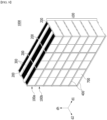
- FIG. 1 is a schematic perspective view of a battery module according to an embodiment of the present disclosure.
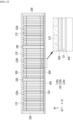
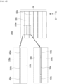
- FIG. 2 is a cross-sectional view illustrating a cross section taken along the cutting line A-A' in FIG. 1 .
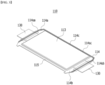
- FIG. 3 is a perspective view illustrating one of the battery cells included in the battery module of FIGS. 1 and 2 .
- FIG. 4 is a perspective view illustrating a state in which the first cover member is removed from the battery module of FIG. 1 .
- the battery module 100 includes a battery cell stack 120 in which a plurality of battery cells 110 are stacked along a first direction d1; at least one vertical beam 200 arranged on both side surfaces of the battery cell stack 120 or arranged in at least one place between the battery cells 110 within the battery cell stack 120; at least one first cover member 300 located on one side of the battery cell stack 120, connected to at least one vertical beam 200, and extending along the first direction d1; and at least one second cover member 400 located on the other side of the battery cell stack 120, connected to at least one of the vertical beams 200, and extending along the first direction d1.
- the battery cell 110 according to the present embodiment may be various types of battery cells, for example, a pouch-type battery cell, a prismatic battery cell, or a cylindrical battery cell.
- the battery cell 110 according to the present embodiment may be a pouch-type battery cell.
- a pouch-type battery cell will be described, but the battery cell 110 according to this embodiment is not limited thereto, and various types of battery cells can be applied.
- the pouch-type battery cell can be formed by housing an electrode assembly in a pouch case made of a laminated sheet including a resin layer and a metal layer and then bonding the outer periphery of the pouch case.
- the battery cell 110 may have a rectangular sheet structure.
- the battery cell 110 may have a structure in which two electrode leads 130 face each other and protrude from one end part and the other end part, respectively.
- One of the electrode leads 130 is a positive electrode lead, and the other is a negative electrode lead.
- the battery cell 110 may have a structure in which two electrode leads 130 face each other and protrude from one end part 114a and the other end part 114b of the cell body 113, respectively. More specifically, the electrode lead 130 is connected to an electrode assembly (not shown), and protrudes from the electrode assembly (not shown) to the outside of the battery cell 110.
- the battery cell 110 can be produced by joining both end parts 114a and 114b of a cell case 114 and one side part 114c connecting the both end parts 114a and 114b in a state in which an electrode assembly (not shown) is housed in a cell case 114.
- the battery cell 110 according to an embodiment of the present disclosure has a total of three sealing parts 114sa, 114sb and 114sc, wherein the sealing parts 114sa, 114sb and 114sc have a structure that is sealed by a method such as thermal fusion, and the remaining other side part may be composed of a folding part 115.
- the cell case 114 may be composed of a laminated sheet including a resin layer and a metal layer.
- the cell case 114 made of the laminate sheet may include an inner resin layer for sealing, a metal layer for prevent penetration of materials, and an outermost outer resin layer. Based on the electrode assembly inside the cell case 114, the inner resin layer may be located at the innermost side, the outer resin layer may be located at the outermost side, and the metal layer may be located between the inner resin layer and the outer resin layer.
- the outer resin layer can have excellent tensile strength and weather resistance relative to the thickness, and can have electrical insulation properties.
- Such an outer resin layer may include polyethylene terephthalate(PET) resin or nylon resin.
- PET polyethylene terephthalate
- the metal layer can prevent air, moisture, and the like from flowing into the pouch-type secondary battery.
- Such a metal layer can include aluminum (Al).
- the inner resin layers may be heat-sealed to each other by heat and/or pressure applied in a state where the electrode assembly is embedded.
- Such an inner resin layer may include casted polypropylene (CPP) or polypropylene (PP).
- the cell case 114 is divided into two portions, wherein at least one of the two portions may be formed with a concave housing part in which the electrode assembly can be seated. Along the outer periphery of this housing part, the inner resin layers of the two portions of the cell case 114 may be joined to each other to provide sealing parts 114sa, 114sb and 114sc.
- the pouch case can be sealed in this manner to manufacture the battery cell 110.
- Such battery cells 110 may be configured in plural numbers, and the plurality of battery cells 110 may be stacked so that they can be electrically connected to each other, thereby forming a battery cell stack 120.
- the battery cells 110 may be stacked along a first direction d1 while standing upright so as to face one surface each of the cell body 113, thereby forming a battery cell stack 120.
- one electrode lead 130 of the battery cells 110 may protrude toward a second direction d2, which will be described later, and the other electrode lead 130 may protrude toward a direction opposite to the second direction d2.
- the vertical beam 200 may be a plate-shaped member having a constant area, and may be arranged in parallel to one surface of the battery cells 110.
- the vertical beam 200 may be arranged in parallel to one surface of the cell body 113 of the battery cell 110. That is, one surface of the vertical beam 200 may be perpendicular to the first direction d1 in which the battery cells 110 are stacked. As will be described later, this vertical beam 200 can control displacement due to swelling of the battery cells 110.
- the vertical beam 200 is arranged on both side surfaces of the battery cell stack 120 or in at least one place between the battery cells 110 within the battery cell stack 120.
- a plurality of vertical beams 200 may be arranged outside the battery cell stack 120 so as to cover both side surfaces of the battery cell stack 120.
- a vertical beam 200 may be located between the battery cells 110 within the battery cell stack 120.
- a total of four vertical beams 200 are illustrated, including two vertical beams 200 located on both side surfaces of the battery cell stack 120 and two vertical beams 200 located between the battery cells 110.
- the vertical beams 200 for covering both side surfaces of the battery cell stack 120 are preferably provided outside the battery cell stack 120.
- the number of the vertical beams 200 located between the battery cells 110 within the battery cell stack 120 is not particularly limited, and can be determined in consideration of the number, size, and the like of the battery cells 110.
- the battery cell stack 120 may be divided into a plurality of sub-battery cell stacks 120a, 120b and 120c.
- the battery cell stack 120 may include first to third sub-battery cell stacks 120a, 120b and 120c partitioned by two vertical beams 200.
- One vertical beam 200 may be located between the first sub-battery cell stack 120a and the second sub-battery cell stack 120b, and another vertical beam 200 may be located between the second sub-battery cell stack 120b and the third sub-battery cell stack 120c.
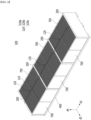
- FIG. 5 is a perspective view illustrating vertical beams and the second cover member included in the battery module of FIG. 1 .
- FIG. 6 is a perspective view showing the vertical beams and the first cover member included in the battery module of FIG. 1 .
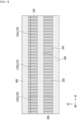
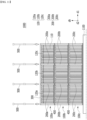
- FIG. 7 is a bottom view of the battery module of FIG. 1 viewed from below.
- FIG. 8 is a plan view of the battery module of FIG. 1 viewed from above.
- the first cover member 300 and the second cover member 400 are located in an area where they do not overlap each other.
- the first cover member 300 and the second cover member 400 according to the present embodiment are respectively connected to the vertical beam 200, and extended along the first direction d1, which is the direction in which the battery cells 110 are stacked.
- at least one first cover member 300 may be located on one side of the battery cell stack 120 along the height direction dh
- at least one second cover member 400 may be located on the other side of the battery cell stack 120 along the height direction dh.
- at least one first cover member 300 and at least one second cover member 400 may be located opposite to each other with the battery cell stack 120 between them.
- the first cover member 300 may be located on the upper part of the battery cell stack 120, and the second cover member 400 may be located at the lower part of the battery cell stack 120.
- the first cover member is located at the lower part of the battery cell stack 120, and the second cover member may also be located at the upper part of the battery cell stack 120.
- the first cover member 300 and the second cover member 400 are located in an area where they do not overlap each other. Therefore, when a plurality of battery modules 100 are stacked along the height direction dh, the second cover member 400 of the battery module 100 located above and the first cover member 300 of the battery module 100 located below may be located without overlapping each other. In another embodiment in which the first cover member is located at the lower part of the battery cell stack 120 and the second cover member is located at the upper part of the battery cell stack 120, the first cover member of the battery module 100 located above and the second cover member of the battery module 100 located below may be located without overlapping each other. In the present embodiment, the first cover member 300 and the second cover member 400 are set so as not to overlap each other, so that the total height when the battery modules 100 are stacked along the height direction dh can be reduced. This will be described below.
- the first cover member 300 and the second cover member 400 may be respectively configured in plural numbers.
- the plurality of first cover members 300 and the plurality of second cover members 400 will be respectively arranged so as to be spaced apart along a second direction d2 perpendicular to both the first direction d1 and the height direction dh.
- the first direction d1, the second direction d2, and the height direction dh are directions indicated for convenience of explanation, and are all directions perpendicular to each other.
- FIGS. 1 and 5 to 8 an embodiment in which the battery module 100 has two first cover members 300 and three second cover members 400, and the two first cover members 300 and the three second cover members 400 are located apart from each other along the second direction d2 is illustrated in FIGS. 1 and 5 to 8 .
- one of the first cover members 300 may be located in an area A2 (see FIG. 5 ) between the second cover members 400. Specifically, an area A2 having an empty space between the second cover members 400 may be formed.
- one of the first cover members 300 may be located in an area A2 between the second cover members 400.
- one of the second cover members 400 may be located in an area A1 (see FIG. 6 ) between the first cover members 300. Specifically, an area A1 having an empty space between the first cover members 300 may be formed.
- one of the second cover members 400 may be located in an area A1 between the first cover members 300.
- the first cover member 300 and the second cover member 400 may be alternately located along the second direction d2.
- At least one of the first cover member 300 or the second cover member 400 may be in the form of a plate having a cavity CV therein. At least one of the first cover member 300 or the second cover member 400 can be realized in a plate shape having a cavity CV, rather than a simple plate shape, thereby compensating the rigidity as so to support the battery cells 110.
- the second cover member 400 may be located at the lower part of the battery cell stack 120. This second cover member 400 may have a plate shape having a cavity CV inside.
- the rigidity of the second cover member 400 is increased, the battery cells can be sufficiently supported, and the stability of the overall structure of the battery module 100 is increased.
- a heat sink 600 for cooling the battery cells 110 may be located between the battery cell stack 120 and the second cover member 400.
- the inside of the heat sink 600 may be formed with a cooling flow passage through which coolant flows. Heat generated in the battery cells 110 is transferred from the edge part of each battery cell 110 to the heat sink 600 and discharged to the outside. That is, the battery module 100 according to the present embodiment may have a water-cooled structure and an edge cooling structure.
- the coolant flowing inside the heat sink 600 is not particularly limited, and as an example, cooling water may be applied.
- a thermal resin layer formed by applying thermal resin may be located between the battery cell stack 120 and the heat sink 600.
- the battery module 100 may further include an end plate 700 that covers both surfaces along the second direction d2 and the opposite direction thereof among the battery cell stack 120.
- This end plate 700 may be a plate-shaped member having a certain area, and may be connected to the vertical beam 200.
- One surface of the end plate 700 may be perpendicular to one surface of the vertical beam 200. That is, in the present embodiment, one surface of the vertical beam 200 may be parallel to each of the second direction d2 and the height direction dh, and one surface of the end plate 700 may be parallel to the first direction d1 and the height direction dh, respectively.
- the battery cells 110 can be protected from the outside by being covered by the vertical beam 200 and the end plate 700.
- a battery pack according to an embodiment of the present disclosure will be described below with reference to FIGS. 9 to 11 , and the like.
- FIG. 9 is a perspective view illustrating a battery pack according to an embodiment of the present disclosure.
- FIG. 10 is a side view of the battery pack of FIG. 9 as viewed from the side.
- FIG. 11 is a cross-sectional view illustrating a state in which a battery pack according to an embodiment of the present disclosure is fixed by a long bolt member.
- the battery pack 1000 includes a plurality of battery modules 100, and at least two battery modules 100 are stacked along the height direction dh.
- the battery modules 100 include a first battery module 100a and a second battery module 100b that are located adjacent to each other along the height direction dh. Further, a third battery module 100c may be located under the second battery module 100b.
- the second cover member 400a of the first battery module 100a and the first cover member 300b of the second battery module 100b are located in a space between the battery cell stack 120 of the first battery module 100a and the battery cell stack 120 of the second battery module 100b.
- the second cover member 400a of the first battery module 100a and the first cover member 300b of the second battery module 100b are located without overlapping each other, so that the height in the structure in which the first battery module 100a and the second battery module 100b are stacked can be reduced.
- the second cover members 400a may be configured in plural number, and the second cover members 400a may be arranged so as to be spaced apart along the second direction d2.
- the first cover members 300b may be configured in plural numbers, and the first cover members 300b may be arranged so as to be spaced apart along the second direction d2.
- the second cover members 400a of the first battery module 100a and the first cover members 300b of the second battery module 100b may be alternately arranged along the second direction d2.
- the second cover member 400b of the second battery module 100b and the first cover member 300c of the third battery module 100c may be located without overlapping each other in the space between the battery cell stack 120 of the second battery module 100b and the battery cell stack 120 of the third battery module 100c.
- the second cover members 400b of the second battery module 100b and the first cover members 300c of the third battery module 100c may be alternately located along the second direction d2.
- the first cover members 300, 300b and 300c and the second cover members 400, 400a and 400b are designed so as not to overlap each other in this manner, whereby when a plurality of battery modules 100a, 100b and 100c are stacked along the height direction dh, the height of the entire battery pack 1000 can be reduced.
- the space utilization of the battery pack 1000 increases by the reduced height, which may lead to an increase in capacity of the entire battery pack 1000.
- the battery pack 1000 may further include a long bolt member 500 that passes through all the vertical beams 200a, 200b and 200c of the battery modules 100a, 100b and 100c stacked along the height direction dh, and is fixed to the vehicle or pack frame.
- a fastening object 1100 to which the long bolt member 500 passing through the vertical beams 200a, 200b and 200c is fastened may be a vehicle or a pack frame.
- the long bolt member 500 may be bolt-coupled to a vehicle or pack frame.
- the long bolt member 500 may pass through a through hole formed in the fastening object 1100 and then be coupled to a nut member (not shown).
- the long bolt member 500 may be directly coupled to a hole having a screw thread provided in the fastening object 1100.
- the battery cells may cause a phenomenon in which the internal electrolyte decomposes to generate gas and the battery cells swells in a process in which charge/discharge is repeated, that is, a swelling phenomenon. If the swelling of the battery cell cannot be controlled, it may cause a structural deformation of the battery module 100 containing the plurality of battery cells 110, and may adversely affect the durability and performance of the battery module 100 and a battery pack including the same.
- the degree of swelling is larger. That is, in order to manufacture high-capacity battery modules and battery packs, it is essential to effectively control the swelling of the battery cells 110 inside the battery module or battery pack. Since the pouch-type battery cells 110 usually have a large degree of swelling in the thickness direction, that is, in the first direction d1, which is the direction in which the battery cells 110 are stacked, the structure directly related to swelling control is a vertical beam 200 that is arranged on both side surfaces of the battery cell stack 120 or between the battery cells 110.
- the battery module 100 has a simplified housing structure that partially covers the battery cell stack 120 through the vertical beam 200, the first cover member 300, and the second cover member 400, rather than a module housing that surrounds the battery cell stack. Thereby, the overall weight and volume of the battery module 100 can be reduced, but it may be difficult to provide sufficient lateral rigidity and durability to control swelling of the battery cells 110.
- the vertical beam 200 is fixed to the vehicle or the pack frame using the long bolt member 500 when stacking the battery modules 100 having a simplified housing structure.
- the vertical beam 200 whose rigidity is strengthened as much as the long bolt member 500 is inserted, is designed to control the displacement due to swelling of the battery cells 110. That is, when the mounting of the stacked battery modules 100 is fixed by the long bolt member 500 passing through the vertical beams 200, the vertical beam 200 simultaneously controls the swelling of the battery cells 110 to supplement the rigidity and durability of the battery module 100 and the battery pack 1000 including the same.
- the long bolt member 500 not only functions to fix the stacked battery modules 100, but also may perform the function similar to a so-called reinforcing rod, which strengthens the rigidity of the vertical beam 200 so as to control swelling of the battery cell 110.
- the one or more battery modules according to embodiments of the present disclosure described above can be mounted together with various control and protection systems such as a BMS (battery management system), a BDU(battery disconnect unit), and a cooling system to form a battery pack.
- BMS battery management system
- BDU battery disconnect unit
- the battery pack can be applied to various devices. Specifically, it can be applied to vehicle means such as an electric bike, an electric vehicle, and a hybrid electric vehicle, or an ESS (Energy Storage System), but is not limited thereto, and can be applied to various devices capable of using a secondary battery. In particular, the battery pack according to the present embodiment can be applied to commercial vehicles.
- vehicle means such as an electric bike, an electric vehicle, and a hybrid electric vehicle, or an ESS (Energy Storage System), but is not limited thereto, and can be applied to various devices capable of using a secondary battery.
- the battery pack according to the present embodiment can be applied to commercial vehicles.
Landscapes
- Chemical & Material Sciences (AREA)
- Chemical Kinetics & Catalysis (AREA)
- Electrochemistry (AREA)
- General Chemical & Material Sciences (AREA)
- Engineering & Computer Science (AREA)
- Aviation & Aerospace Engineering (AREA)
- Battery Mounting, Suspending (AREA)
Abstract
Description
- This application claims the benefit of
Korean Patent Application No. 10-2022-0184467 filed on December 26, 2022 Korean Patent Application No. 10-2023-0183617 filed on December 15, 2023 - The present disclosure relates to a battery module and a battery pack including the same, and more specifically, to a battery module having improved energy density, and a battery pack including the same.
- In modern society, as portable devices such as a mobile phone, a notebook computer, a camcorder and a digital camera has been daily used, the development of technologies in the fields related to mobile devices as described above has been activated. In addition, chargeable/dischargeable secondary batteries are used as a power source for an electric vehicle (EV), a hybrid electric vehicle (HEV), a plug-in hybrid electric vehicle (P-HEV) and the like, in an attempt to solve air pollution and the like caused by existing gasoline vehicles using fossil fuel. Therefore, the demand for development of the secondary battery is growing.
- Currently commercialized secondary batteries include a nickel cadmium battery, a nickel hydrogen battery, a nickel zinc battery, a lithium secondary battery, and the like. Among them, the lithium secondary battery has come into the spotlight because it has advantages, for example, hardly exhibiting memory effects compared to nickel-based secondary batteries and thus being freely charged and discharged, and having very low self-discharge rate and high energy density.
- A lithium secondary battery generally uses lithium-based oxide and a carbon material as a positive electrode active material and a negative electrode active material, respectively. The lithium secondary battery includes an electrode assembly in which a positive electrode plate and a negative electrode plate respectively coated with the positive electrode active material and the negative electrode active material are arranged with a separator between them, and an exterior material or a battery case which hermetically houses the electrode assembly together with an electrolyte.
- Depending on the shape of the exterior material, generally, a lithium secondary battery may be classified into a can type secondary battery where the electrode assembly is incorporated into a metal can and a pouch type battery where the electrode assembly is incorporated into a pouch of an aluminum laminate sheet.
- In the case of a secondary battery used for small-sized devices, two to three battery cells are disposed, but in the case of a secondary battery used for a medium- and large-sized device such as automobiles, a battery module in which a plurality of battery cells are electrically connected is used. In such a battery module, a plurality of battery cells are connected to each other in series or parallel to form a cell assembly, thereby improving capacity and output. Further, one or more battery modules can be mounted together with various control and protection systems such as a BDU (battery disconnect unit), a BMS (battery management system), and a cooling system to form a battery pack.
- Unlike the battery pack mounted on a passenger car, the battery pack mounted on a commercial vehicle can be located in an empty space located at the lower part of the article loading space rather than the seat of a user, and accordingly, a battery pack with a relatively high height is required.
- When configuring a battery pack having high height with conventional battery modules, unnecessary loss of space occurs due to factors such as duplication of components placed between battery modules, assembly tolerances, and space capable of swelling. Therefore, there is a need to develop battery modules and battery packs having new structures that can suppress displacement due to swelling of the battery cells within the battery module, and simultaneously can increase energy density by minimizing the internal space loss.
- It is an object of the present disclosure to provide a battery module that can suppress displacement due to swelling of the battery cells within the battery module, and simultaneously can increase energy density by minimizing the internal space loss, and a battery pack including the same.
- However, the technical problems to be solved by embodiments of the present disclosure are not limited to the above-mentioned problems, and can be variously expanded within the scope of the technical idea included in the present disclosure.
- According to one embodiment of the present disclosure, there is provided a battery module comprising: a battery cell stack in which a plurality of battery cells are stacked along a first direction; at least one vertical beam arranged on both side surfaces of the battery cell stack or arranged in at least one place between the battery cells within the battery cell stack; at least one first cover member located on one side of the battery cell stack, connected to at least one of the vertical beams, and extending along the first direction; and at least one second cover member located on the other side of the battery cell stack, connected to at least one of the vertical beams, and extending along the first direction, wherein, when viewed along a height direction perpendicular to the first direction, the first cover member and the second cover member are located in an area where they do not overlap each other.
- The at least one first cover member may be located on one side of the battery cell stack along the height direction, and the at least one second cover member may be located on the other side of the battery cell stack along the height direction.
- The at least one first cover member and the at least one second cover member may be located opposite to each other with the battery cell stack between them.
- At least one of the first cover member or the second cover member may have a plate shape having a cavity therein.
- The second cover member may be located at the lower part of the battery cell stack, and may have a plate shape having a cavity therein.
- The first cover member and the second cover member may be respectively configured in plural numbers. The plurality of first cover members and the plurality of second cover members may be respectively arranged so as to be spaced apart along a second direction perpendicular to both the first direction and the height direction.
- When viewed along the height direction, one of the first cover members may be located in an area between the second cover members.
- When viewed along the height direction, one of the second cover members may be located in an area between the first cover members.
- According to one embodiment of the present disclosure, there is provided a battery pack comprising: a plurality of the battery modules, wherein the at least two of the battery modules are stacked along a height direction, wherein the battery modules include a first battery module and a second battery module that are located adjacent to each other along the height direction, and wherein the second cover member of the first battery module and the first cover member of the second battery module are located in a space between the battery cell stack of the first battery module and the battery cell stack of the second battery module.
- In the battery module, the first cover member and the second cover member may be respectively configured in plural numbers, and the plurality of first cover members and the plurality of second cover members may be respectively arranged so as to be spaced apart along a second direction perpendicular to both the first direction and the height direction.
- The second cover member of the first battery module and the first cover member of the second battery module may be alternately located along a second direction perpendicular to both the first direction and the height direction.
- The battery pack may further comprise a long bolt member that passes through all the vertical beams of the battery modules stacked along the height direction, and is fixed to a vehicle or pack frame.
- According to embodiments of the present disclosure, the first cover member and the second cover member of the battery module can be located in an area where they do not overlap each other, thereby reducing the total height when battery modules are stacked along the height direction. That is, it is possible to reduce space and increase energy density.
- In addition, the battery modules stacked in the height direction can be fixed with a long bolt member passing through the vertical beams of the battery modules, thereby increasing the structural stability of the battery pack, and effectively suppressing displacement due to swelling of the battery cells inside the battery module.
- Effects obtainable from the present disclosure are not limited to the effects mentioned above, and additional other effects not mentioned herein will be clearly understood from the description of the appended claims by those skilled in the art.
-
-
FIG. 1 is a schematic perspective view of a battery module according to an embodiment of the present disclosure. -
FIG. 2 is a cross-sectional view illustrating a cross section taken along the cutting line A-A' inFIG. 1 . -
FIG. 3 is a perspective view illustrating one of the battery cells included in the battery module ofFIGS. 1 and2 . -
FIG. 4 is a perspective view illustrating a state in which the first cover member is removed from the battery module ofFIG. 1 . -
FIG. 5 is a perspective view illustrating vertical beams and the second cover member included in the battery module ofFIG. 1 . -
FIG. 6 is a perspective view showing the vertical beams and the first cover member included in the battery module ofFIG. 1 . -
FIG. 7 is a bottom view of the battery module ofFIG. 1 viewed from below. -
FIG. 8 is a plan view of the battery module ofFIG. 1 viewed from above. -
FIG. 9 is a perspective view illustrating a battery pack according to an embodiment of the present disclosure. -
FIG. 10 is a side view of the battery pack ofFIG. 9 as viewed from the side. -
FIG. 11 is a cross-sectional view illustrating a state in which a battery pack according to an embodiment of the present disclosure is fixed by a long bolt member. - Hereinafter, various embodiments of the present disclosure will be described in detail with reference to the accompanying drawings so that those skilled in the art can easily carry out them. The present disclosure may be modified in various different ways, and is not limited to the embodiments set forth herein.
- A description of portions that are not related to the description will be omitted for clarity, and same reference numerals designate same or like elements throughout the description.
- Further, in the drawings, the size and thickness of each element are arbitrarily illustrated for convenience of description, and the present disclosure is not necessarily limited to those illustrated in the drawings. In the drawings, the thickness of layers, areas, etc. are exaggerated for clarity. In the drawings, for convenience of description, the thicknesses of a part and an area are exaggerated.
- Further, it will be understood that when an element such as a layer, film, region, or plate is referred to as being "on" or "above" another element, it can be directly on the other element or intervening elements may also be present. In contrast, when an element is referred to as being "directly on" another element, it means that other intervening elements are not present. Further, a certain part being located "above" or "on" a reference portion means the certain part being located above or below the reference portion and does not particularly mean the certain part "above" or "on" toward an opposite direction of gravity.
- Further, throughout the description, when a portion is referred to as "including" or "comprising" a certain component, it means that the portion can further include other components, without excluding the other components, unless otherwise stated.
- Further, throughout the description, when referred to as "planar", it means when a target portion is viewed from the upper side, and when it is referred to as "cross-sectional", it means when a target portion is viewed from the side of a cross section cut vertically.
-
FIG. 1 is a schematic perspective view of a battery module according to an embodiment of the present disclosure.FIG. 2 is a cross-sectional view illustrating a cross section taken along the cutting line A-A' inFIG. 1 .FIG. 3 is a perspective view illustrating one of the battery cells included in the battery module ofFIGS. 1 and2 .FIG. 4 is a perspective view illustrating a state in which the first cover member is removed from the battery module ofFIG. 1 . - Referring to
FIGS. 1 to 4 , thebattery module 100 according to an embodiment of the present disclosure includes abattery cell stack 120 in which a plurality ofbattery cells 110 are stacked along a first direction d1; at least onevertical beam 200 arranged on both side surfaces of thebattery cell stack 120 or arranged in at least one place between thebattery cells 110 within thebattery cell stack 120; at least onefirst cover member 300 located on one side of thebattery cell stack 120, connected to at least onevertical beam 200, and extending along the first direction d1; and at least onesecond cover member 400 located on the other side of thebattery cell stack 120, connected to at least one of thevertical beams 200, and extending along the first direction d1. - The
battery cell 110 according to the present embodiment may be various types of battery cells, for example, a pouch-type battery cell, a prismatic battery cell, or a cylindrical battery cell. In one example, as illustrated inFIG. 3 , thebattery cell 110 according to the present embodiment may be a pouch-type battery cell. Below, a pouch-type battery cell will be described, but thebattery cell 110 according to this embodiment is not limited thereto, and various types of battery cells can be applied. The pouch-type battery cell can be formed by housing an electrode assembly in a pouch case made of a laminated sheet including a resin layer and a metal layer and then bonding the outer periphery of the pouch case. Thebattery cell 110 may have a rectangular sheet structure. For example, thebattery cell 110 according to the present embodiment may have a structure in which two electrode leads 130 face each other and protrude from one end part and the other end part, respectively. One of the electrode leads 130 is a positive electrode lead, and the other is a negative electrode lead. - In particular, referring to
FIG. 3 , thebattery cell 110 according to the present embodiment may have a structure in which two electrode leads 130 face each other and protrude from oneend part 114a and theother end part 114b of thecell body 113, respectively. More specifically, theelectrode lead 130 is connected to an electrode assembly (not shown), and protrudes from the electrode assembly (not shown) to the outside of thebattery cell 110. - Meanwhile, the
battery cell 110 can be produced by joining bothend parts cell case 114 and oneside part 114c connecting the bothend parts cell case 114. In other words, thebattery cell 110 according to an embodiment of the present disclosure has a total of three sealing parts 114sa, 114sb and 114sc, wherein the sealing parts 114sa, 114sb and 114sc have a structure that is sealed by a method such as thermal fusion, and the remaining other side part may be composed of afolding part 115. Thecell case 114 may be composed of a laminated sheet including a resin layer and a metal layer. - In
FIG. 3 , only thebattery cell 110 having a structure in which the electrode leads 130 protrude in both directions has been described, but in other embodiments of the present disclosure, it goes without saying that a unidirectional pouch-type battery cell in which the electrode leads protrude together in one direction can also be used. - The
cell case 114 made of the laminate sheet may include an inner resin layer for sealing, a metal layer for prevent penetration of materials, and an outermost outer resin layer. Based on the electrode assembly inside thecell case 114, the inner resin layer may be located at the innermost side, the outer resin layer may be located at the outermost side, and the metal layer may be located between the inner resin layer and the outer resin layer. - In order to protect the electrode assembly from the outside, the outer resin layer can have excellent tensile strength and weather resistance relative to the thickness, and can have electrical insulation properties. Such an outer resin layer may include polyethylene terephthalate(PET) resin or nylon resin. The metal layer can prevent air, moisture, and the like from flowing into the pouch-type secondary battery. Such a metal layer can include aluminum (Al). The inner resin layers may be heat-sealed to each other by heat and/or pressure applied in a state where the electrode assembly is embedded. Such an inner resin layer may include casted polypropylene (CPP) or polypropylene (PP).
- The
cell case 114 is divided into two portions, wherein at least one of the two portions may be formed with a concave housing part in which the electrode assembly can be seated. Along the outer periphery of this housing part, the inner resin layers of the two portions of thecell case 114 may be joined to each other to provide sealing parts 114sa, 114sb and 114sc. The pouch case can be sealed in this manner to manufacture thebattery cell 110. -
Such battery cells 110 may be configured in plural numbers, and the plurality ofbattery cells 110 may be stacked so that they can be electrically connected to each other, thereby forming abattery cell stack 120. In particular, thebattery cells 110 may be stacked along a first direction d1 while standing upright so as to face one surface each of thecell body 113, thereby forming abattery cell stack 120. Thereby, oneelectrode lead 130 of thebattery cells 110 may protrude toward a second direction d2, which will be described later, and theother electrode lead 130 may protrude toward a direction opposite to the second direction d2. - The
vertical beam 200 may be a plate-shaped member having a constant area, and may be arranged in parallel to one surface of thebattery cells 110. Thevertical beam 200 may be arranged in parallel to one surface of thecell body 113 of thebattery cell 110. That is, one surface of thevertical beam 200 may be perpendicular to the first direction d1 in which thebattery cells 110 are stacked. As will be described later, thisvertical beam 200 can control displacement due to swelling of thebattery cells 110. As described above, thevertical beam 200 is arranged on both side surfaces of thebattery cell stack 120 or in at least one place between thebattery cells 110 within thebattery cell stack 120. As an example, a plurality ofvertical beams 200 may be arranged outside thebattery cell stack 120 so as to cover both side surfaces of thebattery cell stack 120. Alternatively, avertical beam 200 may be located between thebattery cells 110 within thebattery cell stack 120. InFIGS. 1 to 4 , a total of fourvertical beams 200 are illustrated, including twovertical beams 200 located on both side surfaces of thebattery cell stack 120 and twovertical beams 200 located between thebattery cells 110. For structural stability, thevertical beams 200 for covering both side surfaces of thebattery cell stack 120 are preferably provided outside thebattery cell stack 120. Meanwhile, the number of thevertical beams 200 located between thebattery cells 110 within thebattery cell stack 120 is not particularly limited, and can be determined in consideration of the number, size, and the like of thebattery cells 110. - Due to the
vertical beam 200 arranged between thebattery cells 110, thebattery cell stack 120 may be divided into a plurality ofsub-battery cell stacks battery cell stack 120 may include first to thirdsub-battery cell stacks vertical beams 200. Onevertical beam 200 may be located between the firstsub-battery cell stack 120a and the secondsub-battery cell stack 120b, and anothervertical beam 200 may be located between the secondsub-battery cell stack 120b and the thirdsub-battery cell stack 120c. -
FIG. 5 is a perspective view illustrating vertical beams and the second cover member included in the battery module ofFIG. 1 .FIG. 6 is a perspective view showing the vertical beams and the first cover member included in the battery module ofFIG. 1 .FIG. 7 is a bottom view of the battery module ofFIG. 1 viewed from below.FIG. 8 is a plan view of the battery module ofFIG. 1 viewed from above. - Referring to
FIGS. 1 ,2 , and5 to 8 together, in thebattery module 100 according to the present embodiment, when viewed along the height direction dh perpendicular to the first direction d1, thefirst cover member 300 and thesecond cover member 400 are located in an area where they do not overlap each other. - The
first cover member 300 and thesecond cover member 400 according to the present embodiment are respectively connected to thevertical beam 200, and extended along the first direction d1, which is the direction in which thebattery cells 110 are stacked. Specifically, at least onefirst cover member 300 may be located on one side of thebattery cell stack 120 along the height direction dh, and at least onesecond cover member 400 may be located on the other side of thebattery cell stack 120 along the height direction dh. In particular, at least onefirst cover member 300 and at least onesecond cover member 400 may be located opposite to each other with thebattery cell stack 120 between them. As an example, as shown inFIGS. 1 ,2 ,5 and6 , thefirst cover member 300 may be located on the upper part of thebattery cell stack 120, and thesecond cover member 400 may be located at the lower part of thebattery cell stack 120. In another embodiment of the present disclosure, the first cover member is located at the lower part of thebattery cell stack 120, and the second cover member may also be located at the upper part of thebattery cell stack 120. - When viewed along the height direction dh, the
first cover member 300 and thesecond cover member 400 are located in an area where they do not overlap each other. Therefore, when a plurality ofbattery modules 100 are stacked along the height direction dh, thesecond cover member 400 of thebattery module 100 located above and thefirst cover member 300 of thebattery module 100 located below may be located without overlapping each other. In another embodiment in which the first cover member is located at the lower part of thebattery cell stack 120 and the second cover member is located at the upper part of thebattery cell stack 120, the first cover member of thebattery module 100 located above and the second cover member of thebattery module 100 located below may be located without overlapping each other. In the present embodiment, thefirst cover member 300 and thesecond cover member 400 are set so as not to overlap each other, so that the total height when thebattery modules 100 are stacked along the height direction dh can be reduced. This will be described below. - Meanwhile, in the
battery module 100, thefirst cover member 300 and thesecond cover member 400 may be respectively configured in plural numbers. The plurality offirst cover members 300 and the plurality ofsecond cover members 400 will be respectively arranged so as to be spaced apart along a second direction d2 perpendicular to both the first direction d1 and the height direction dh. In this specification, the first direction d1, the second direction d2, and the height direction dh are directions indicated for convenience of explanation, and are all directions perpendicular to each other. As an example, an embodiment in which thebattery module 100 has twofirst cover members 300 and threesecond cover members 400, and the twofirst cover members 300 and the threesecond cover members 400 are located apart from each other along the second direction d2 is illustrated inFIGS. 1 and5 to 8 . - Further, when viewed along the height direction dh, one of the
first cover members 300 may be located in an area A2 (seeFIG. 5 ) between thesecond cover members 400. Specifically, an area A2 having an empty space between thesecond cover members 400 may be formed. When viewed along the height direction dh, one of thefirst cover members 300 may be located in an area A2 between thesecond cover members 400. Further, when viewed along the height direction dh, one of thesecond cover members 400 may be located in an area A1 (seeFIG. 6 ) between thefirst cover members 300. Specifically, an area A1 having an empty space between thefirst cover members 300 may be formed. When viewed along the height direction dh, one of thesecond cover members 400 may be located in an area A1 between thefirst cover members 300. In one embodiment of the present disclosure, when viewed along the height direction dh, thefirst cover member 300 and thesecond cover member 400 may be alternately located along the second direction d2. - Meanwhile, referring again to
FIG. 2 , at least one of thefirst cover member 300 or thesecond cover member 400 may be in the form of a plate having a cavity CV therein. At least one of thefirst cover member 300 or thesecond cover member 400 can be realized in a plate shape having a cavity CV, rather than a simple plate shape, thereby compensating the rigidity as so to support thebattery cells 110. In particular, as described above, thesecond cover member 400 may be located at the lower part of thebattery cell stack 120. Thissecond cover member 400 may have a plate shape having a cavity CV inside. As thesecond cover member 400 located at the lower part of thebattery cell stack 120 is realized in a plate shape having a cavity CV, the rigidity of thesecond cover member 400 is increased, the battery cells can be sufficiently supported, and the stability of the overall structure of thebattery module 100 is increased. - Meanwhile, a
heat sink 600 for cooling thebattery cells 110 may be located between thebattery cell stack 120 and thesecond cover member 400. The inside of theheat sink 600 may be formed with a cooling flow passage through which coolant flows. Heat generated in thebattery cells 110 is transferred from the edge part of eachbattery cell 110 to theheat sink 600 and discharged to the outside. That is, thebattery module 100 according to the present embodiment may have a water-cooled structure and an edge cooling structure. The coolant flowing inside theheat sink 600 is not particularly limited, and as an example, cooling water may be applied. In addition, although not specifically illustrated, a thermal resin layer formed by applying thermal resin may be located between thebattery cell stack 120 and theheat sink 600. - Meanwhile, the
battery module 100 according to the present embodiment may further include anend plate 700 that covers both surfaces along the second direction d2 and the opposite direction thereof among thebattery cell stack 120. Thisend plate 700 may be a plate-shaped member having a certain area, and may be connected to thevertical beam 200. One surface of theend plate 700 may be perpendicular to one surface of thevertical beam 200. That is, in the present embodiment, one surface of thevertical beam 200 may be parallel to each of the second direction d2 and the height direction dh, and one surface of theend plate 700 may be parallel to the first direction d1 and the height direction dh, respectively. Thebattery cells 110 can be protected from the outside by being covered by thevertical beam 200 and theend plate 700. - A battery pack according to an embodiment of the present disclosure will be described below with reference to
FIGS. 9 to 11 , and the like. -
FIG. 9 is a perspective view illustrating a battery pack according to an embodiment of the present disclosure.FIG. 10 is a side view of the battery pack ofFIG. 9 as viewed from the side.FIG. 11 is a cross-sectional view illustrating a state in which a battery pack according to an embodiment of the present disclosure is fixed by a long bolt member. - Referring to
FIGS. 9 to 11 together withFIGS. 1 and4 to 8 , thebattery pack 1000 according to an embodiment of the present disclosure includes a plurality ofbattery modules 100, and at least twobattery modules 100 are stacked along the height direction dh. Thebattery modules 100 include afirst battery module 100a and asecond battery module 100b that are located adjacent to each other along the height direction dh. Further, athird battery module 100c may be located under thesecond battery module 100b. - The
second cover member 400a of thefirst battery module 100a and thefirst cover member 300b of thesecond battery module 100b are located in a space between thebattery cell stack 120 of thefirst battery module 100a and thebattery cell stack 120 of thesecond battery module 100b. As described above, when viewed along the height direction dh, since thefirst cover member 300 and thesecond cover member 400 are located in an area where they do not overlap each other, thesecond cover member 400a of thefirst battery module 100a and thefirst cover member 300b of thesecond battery module 100b are located without overlapping each other, so that the height in the structure in which thefirst battery module 100a and thesecond battery module 100b are stacked can be reduced. - Further, in the
first battery module 100a, thesecond cover members 400a may be configured in plural number, and thesecond cover members 400a may be arranged so as to be spaced apart along the second direction d2. In thesecond battery module 100b, thefirst cover members 300b may be configured in plural numbers, and thefirst cover members 300b may be arranged so as to be spaced apart along the second direction d2. - When the
first battery module 100a and thesecond battery module 100b are stacked along the height direction dh, thesecond cover members 400a of thefirst battery module 100a and thefirst cover members 300b of thesecond battery module 100b may be alternately arranged along the second direction d2. - The relationship with the
first battery module 100a located above thesecond battery module 100b has been described above, but a similar structure can be applied even to the relationship with thethird battery module 100c located under thesecond battery module 100b. Specifically, thesecond cover member 400b of thesecond battery module 100b and thefirst cover member 300c of thethird battery module 100c may be located without overlapping each other in the space between thebattery cell stack 120 of thesecond battery module 100b and thebattery cell stack 120 of thethird battery module 100c. Thesecond cover members 400b of thesecond battery module 100b and thefirst cover members 300c of thethird battery module 100c may be alternately located along the second direction d2. Thefirst cover members second cover members battery modules entire battery pack 1000 can be reduced. The space utilization of thebattery pack 1000 increases by the reduced height, which may lead to an increase in capacity of theentire battery pack 1000. - Meanwhile, the
battery pack 1000 according to the present embodiment may further include along bolt member 500 that passes through all thevertical beams battery modules FIG. 11 , afastening object 1100 to which thelong bolt member 500 passing through thevertical beams long bolt member 500 may be bolt-coupled to a vehicle or pack frame. For example, thelong bolt member 500 may pass through a through hole formed in thefastening object 1100 and then be coupled to a nut member (not shown). As another example, thelong bolt member 500 may be directly coupled to a hole having a screw thread provided in thefastening object 1100. - The battery cells may cause a phenomenon in which the internal electrolyte decomposes to generate gas and the battery cells swells in a process in which charge/discharge is repeated, that is, a swelling phenomenon. If the swelling of the battery cell cannot be controlled, it may cause a structural deformation of the
battery module 100 containing the plurality ofbattery cells 110, and may adversely affect the durability and performance of thebattery module 100 and a battery pack including the same. - In particular, recently, pure Si cells and high SiO content cells are used as battery cells for manufacturing high-capacity battery modules and battery packs, and in the case of the above cells, the degree of swelling is larger. That is, in order to manufacture high-capacity battery modules and battery packs, it is essential to effectively control the swelling of the
battery cells 110 inside the battery module or battery pack. Since the pouch-type battery cells 110 usually have a large degree of swelling in the thickness direction, that is, in the first direction d1, which is the direction in which thebattery cells 110 are stacked, the structure directly related to swelling control is avertical beam 200 that is arranged on both side surfaces of thebattery cell stack 120 or between thebattery cells 110. - The
battery module 100 according to the present embodiment has a simplified housing structure that partially covers thebattery cell stack 120 through thevertical beam 200, thefirst cover member 300, and thesecond cover member 400, rather than a module housing that surrounds the battery cell stack. Thereby, the overall weight and volume of thebattery module 100 can be reduced, but it may be difficult to provide sufficient lateral rigidity and durability to control swelling of thebattery cells 110. - Therefore, in the
battery pack 1000 according to the present embodiment, thevertical beam 200 is fixed to the vehicle or the pack frame using thelong bolt member 500 when stacking thebattery modules 100 having a simplified housing structure. Thereby, thevertical beam 200, whose rigidity is strengthened as much as thelong bolt member 500 is inserted, is designed to control the displacement due to swelling of thebattery cells 110. That is, when the mounting of the stackedbattery modules 100 is fixed by thelong bolt member 500 passing through thevertical beams 200, thevertical beam 200 simultaneously controls the swelling of thebattery cells 110 to supplement the rigidity and durability of thebattery module 100 and thebattery pack 1000 including the same. In other words, thelong bolt member 500 according to the present embodiment not only functions to fix the stackedbattery modules 100, but also may perform the function similar to a so-called reinforcing rod, which strengthens the rigidity of thevertical beam 200 so as to control swelling of thebattery cell 110. - The terms representing directions such as the front side, the rear side, the left side, the right side, the upper side, and the lower side have been used in the present embodiment, but it is obvious to those skilled in the art that the terms used are provided simply for convenience of description, and may become different according to the position of an object, the position of an observer, or the like.
- The one or more battery modules according to embodiments of the present disclosure described above can be mounted together with various control and protection systems such as a BMS (battery management system), a BDU(battery disconnect unit), and a cooling system to form a battery pack.
- The battery pack can be applied to various devices. Specifically, it can be applied to vehicle means such as an electric bike, an electric vehicle, and a hybrid electric vehicle, or an ESS (Energy Storage System), but is not limited thereto, and can be applied to various devices capable of using a secondary battery. In particular, the battery pack according to the present embodiment can be applied to commercial vehicles.
- Although the invention has been described in detail with reference to preferred embodiments thereof, the scope of the present disclosure is not limited thereto, and various modifications and improvements can be made by those skilled in the art using the basic concepts of the present disclosure, which are defined in the appended claims, which also falls within the scope of the present disclosure.
-
- 100: battery module
- 100a: first battery module
- 100b: second battery module
- 100c: third battery module
- 110: battery cell
- 120: battery cell stack
- 200: vertical beam
- 300: first cover member
- 400: second cover member
- 500: long bolt member
Claims (12)
- A battery module comprising:a battery cell stack in which a plurality of battery cells are stacked along a first direction;at least one vertical beam arranged on both side surfaces of the battery cell stack or arranged in at least one place between the battery cells within the battery cell stack;at least one first cover member located on one side of the battery cell stack, connected to at least one of the vertical beams, and extending along the first direction; andat least one second cover member located on the other side of the battery cell stack, connected to at least one of the vertical beams, and extending along the first direction,wherein, when viewed along a height direction perpendicular to the first direction, the first cover member and the second cover member are located in an area where they do not overlap each other.
- The battery module as claimed in claim 1, wherein:the at least one first cover member is located on one side of the battery cell stack along the height direction, andthe at least one second cover member is located on the other side of the battery cell stack along the height direction.
- The battery module as claimed in claim 1, wherein:
the at least one first cover member and the at least one second cover member are located opposite to each other with the battery cell stack between them. - The battery module as claimed in claim 1, wherein:
at least one of the first cover member or the second cover member has a plate shape having a cavity therein. - The battery module as claimed in claim 1, wherein:
the second cover member is located at the lower part of the battery cell stack, and has a plate shape having a cavity therein. - The battery module as claimed in claim 1, wherein:the first cover member and the second cover member are respectively configured in plural numbers, andthe plurality of first cover members and the plurality of second cover members are respectively arranged so as to be spaced apart along a second direction perpendicular to both the first direction and the height direction.
- The battery module as claimed in claim 6, wherein:
when viewed along the height direction, one of the first cover members is located in an area between the second cover members. - The battery module as claimed in claim 6, wherein:
when viewed along the height direction, one of the second cover members is located in an area between the first cover members. - A battery pack comprising:a plurality of the battery modules as claimed in claim 1,wherein the at least two of the battery modules are stacked along a height direction,wherein the battery modules include a first battery module and a second battery module that are located adjacent to each other along the height direction, andwherein the second cover member of the first battery module and the first cover member of the second battery module are located in a space between the battery cell stack of the first battery module and the battery cell stack of the second battery module.
- The battery pack as claimed in claim 9, wherein:in the battery module, the first cover member and the second cover member are respectively configured in plural numbers, andthe plurality of first cover members and the plurality of second cover members are respectively arranged so as to be spaced apart along a second direction perpendicular to both the first direction and the height direction.
- The battery pack as claimed in claim 9, wherein:
the second cover member of the first battery module and the first cover member of the second battery module are alternately located along a second direction perpendicular to both the first direction and the height direction. - The battery pack as claimed in claim 9, further comprising:
a long bolt member that passes through all the vertical beams of the battery modules stacked along the height direction, and is fixed to a vehicle or pack frame.
Applications Claiming Priority (3)
| Application Number | Priority Date | Filing Date | Title |
|---|---|---|---|
| KR20220184467 | 2022-12-26 | ||
| KR1020230183617A KR20240102851A (en) | 2022-12-26 | 2023-12-15 | Battery module and battery pack including the same |
| PCT/KR2023/020854 WO2024144036A1 (en) | 2022-12-26 | 2023-12-18 | Battery module and battery pack including same |
Publications (2)
| Publication Number | Publication Date |
|---|---|
| EP4531183A1 true EP4531183A1 (en) | 2025-04-02 |
| EP4531183A4 EP4531183A4 (en) | 2025-10-22 |
Family
ID=91718563
Family Applications (1)
| Application Number | Title | Priority Date | Filing Date |
|---|---|---|---|
| EP23912711.1A Pending EP4531183A4 (en) | 2022-12-26 | 2023-12-18 | BATTERY MODULE AND BATTERY PACK |
Country Status (5)
| Country | Link |
|---|---|
| US (1) | US20250364656A1 (en) |
| EP (1) | EP4531183A4 (en) |
| JP (1) | JP7838127B2 (en) |
| CN (1) | CN119487682A (en) |
| WO (1) | WO2024144036A1 (en) |
Family Cites Families (11)
| Publication number | Priority date | Publication date | Assignee | Title |
|---|---|---|---|---|
| US6773846B2 (en) * | 2002-08-19 | 2004-08-10 | Allis Electric Co., Ltd. | Mobile rack type battery box for UPS system |
| KR100892046B1 (en) * | 2006-09-18 | 2009-04-07 | 주식회사 엘지화학 | Battery module and medium and large battery packs containing it |
| CN103201876B (en) * | 2010-11-17 | 2015-11-25 | 本田技研工业株式会社 | Vehicle battery unit |
| JP5656743B2 (en) * | 2011-05-30 | 2015-01-21 | トヨタ自動車株式会社 | Battery pack and battery pack holder |
| JP2017098014A (en) * | 2015-11-20 | 2017-06-01 | 三菱自動車工業株式会社 | Battery module |
| EP3346517B1 (en) * | 2017-01-04 | 2023-08-30 | Samsung SDI Co., Ltd | Battery system |
| HRP20221219T1 (en) * | 2017-02-17 | 2022-12-23 | Mubea Carbo Tech Gmbh | Battery structure and protector |
| KR102313023B1 (en) * | 2018-11-29 | 2021-10-13 | 주식회사 엘지에너지솔루션 | Battery Pack Having Battery Module |
| CN111668527B (en) * | 2019-03-07 | 2024-10-22 | 宁德时代新能源科技股份有限公司 | Battery module and battery pack |
| CN113889708B (en) * | 2020-06-19 | 2022-11-11 | 比亚迪股份有限公司 | Vehicle and battery pack thereof |
| KR102953580B1 (en) * | 2020-08-26 | 2026-04-15 | 주식회사 엘지에너지솔루션 | Large battery module and a bettery pack including the same |
-
2023
- 2023-12-18 CN CN202380051567.9A patent/CN119487682A/en active Pending
- 2023-12-18 US US18/876,530 patent/US20250364656A1/en active Pending
- 2023-12-18 JP JP2024570549A patent/JP7838127B2/en active Active
- 2023-12-18 EP EP23912711.1A patent/EP4531183A4/en active Pending
- 2023-12-18 WO PCT/KR2023/020854 patent/WO2024144036A1/en not_active Ceased
Also Published As
| Publication number | Publication date |
|---|---|
| JP7838127B2 (en) | 2026-03-31 |
| WO2024144036A1 (en) | 2024-07-04 |
| US20250364656A1 (en) | 2025-11-27 |
| JP2025519189A (en) | 2025-06-24 |
| CN119487682A (en) | 2025-02-18 |
| EP4531183A4 (en) | 2025-10-22 |
Similar Documents
| Publication | Publication Date | Title |
|---|---|---|
| US20220158270A1 (en) | Battery Pack and Device Including the Same | |
| EP4300686B1 (en) | Battery module and battery pack including the same | |
| KR102892942B1 (en) | Battery pack | |
| EP4199208B1 (en) | Battery pack | |
| EP4210154A1 (en) | Battery pack and device comprising same | |
| US20260088421A1 (en) | Battery module and battery pack including the same | |
| KR102813936B1 (en) | Battery module and battery pack including the same | |
| EP4170793A1 (en) | Battery module and battery pack including same | |
| EP4539227A1 (en) | Battery pack and device including the same | |
| EP4181296B1 (en) | Battery pack and device including the same | |
| US20250364656A1 (en) | Battery module and battery pack including the same | |
| KR20210127321A (en) | Battery pack and device including the same | |
| EP4261985A1 (en) | Battery pack and device including same | |
| KR20240102851A (en) | Battery module and battery pack including the same | |
| EP4661178A1 (en) | Battery pack and device including same | |
| US20250030116A1 (en) | Battery Pack and Device Including the Same | |
| EP4425670B1 (en) | Battery pack | |
| EP4607670A1 (en) | Battery module and battery pack including same | |
| KR102754503B1 (en) | Battery module and device including the same | |
| KR20250169770A (en) | Battery pack and device including the same | |
| KR20240012307A (en) | Battery cell unit and battery cell assembly including the same | |
| KR20250124527A (en) | Battery module and battery pack including the same |
Legal Events
| Date | Code | Title | Description |
|---|---|---|---|
| STAA | Information on the status of an ep patent application or granted ep patent |
Free format text: STATUS: THE INTERNATIONAL PUBLICATION HAS BEEN MADE |
|
| PUAI | Public reference made under article 153(3) epc to a published international application that has entered the european phase |
Free format text: ORIGINAL CODE: 0009012 |
|
| STAA | Information on the status of an ep patent application or granted ep patent |
Free format text: STATUS: REQUEST FOR EXAMINATION WAS MADE |
|
| 17P | Request for examination filed |
Effective date: 20241224 |
|
| AK | Designated contracting states |
Kind code of ref document: A1 Designated state(s): AL AT BE BG CH CY CZ DE DK EE ES FI FR GB GR HR HU IE IS IT LI LT LU LV MC ME MK MT NL NO PL PT RO RS SE SI SK SM TR |
|
| A4 | Supplementary search report drawn up and despatched |
Effective date: 20250924 |
|
| RIC1 | Information provided on ipc code assigned before grant |
Ipc: H01M 50/258 20210101AFI20250918BHEP Ipc: H01M 50/264 20210101ALI20250918BHEP Ipc: H01M 50/249 20210101ALI20250918BHEP Ipc: H01M 50/289 20210101ALI20250918BHEP |
|
| GRAP | Despatch of communication of intention to grant a patent |
Free format text: ORIGINAL CODE: EPIDOSNIGR1 |
|
| RIC1 | Information provided on ipc code assigned before grant |
Ipc: H01M 50/258 20210101AFI20260114BHEP Ipc: H01M 50/264 20210101ALI20260114BHEP Ipc: H01M 50/249 20210101ALI20260114BHEP Ipc: H01M 50/289 20210101ALI20260114BHEP |
|
| STAA | Information on the status of an ep patent application or granted ep patent |
Free format text: STATUS: GRANT OF PATENT IS INTENDED |
|
| INTG | Intention to grant announced |
Effective date: 20260218 |
|
| DAV | Request for validation of the european patent (deleted) | ||
| DAX | Request for extension of the european patent (deleted) | ||
| P01 | Opt-out of the competence of the unified patent court (upc) registered |
Free format text: CASE NUMBER: UPC_APP_0009416_4531183/2026 Effective date: 20260311 |