EP4531178A1 - Pack case with improved heat dissipation structure - Google Patents
Pack case with improved heat dissipation structure Download PDFInfo
- Publication number
- EP4531178A1 EP4531178A1 EP24764247.3A EP24764247A EP4531178A1 EP 4531178 A1 EP4531178 A1 EP 4531178A1 EP 24764247 A EP24764247 A EP 24764247A EP 4531178 A1 EP4531178 A1 EP 4531178A1
- Authority
- EP
- European Patent Office
- Prior art keywords
- base plate
- battery
- pack
- pack case
- battery module
- Prior art date
- Legal status (The legal status is an assumption and is not a legal conclusion. Google has not performed a legal analysis and makes no representation as to the accuracy of the status listed.)
- Granted
Links
Images


Classifications
-
- H—ELECTRICITY
- H01—ELECTRIC ELEMENTS
- H01M—PROCESSES OR MEANS, e.g. BATTERIES, FOR THE DIRECT CONVERSION OF CHEMICAL ENERGY INTO ELECTRICAL ENERGY
- H01M50/00—Constructional details or processes of manufacture of the non-active parts of electrochemical cells other than fuel cells, e.g. hybrid cells
- H01M50/20—Mountings; Secondary casings or frames; Racks, modules or packs; Suspension devices; Shock absorbers; Transport or carrying devices; Holders
- H01M50/204—Racks, modules or packs for multiple batteries or multiple cells
- H01M50/207—Racks, modules or packs for multiple batteries or multiple cells characterised by their shape
-
- H—ELECTRICITY
- H01—ELECTRIC ELEMENTS
- H01M—PROCESSES OR MEANS, e.g. BATTERIES, FOR THE DIRECT CONVERSION OF CHEMICAL ENERGY INTO ELECTRICAL ENERGY
- H01M10/00—Secondary cells; Manufacture thereof
- H01M10/60—Heating or cooling; Temperature control
- H01M10/65—Means for temperature control structurally associated with the cells
- H01M10/653—Means for temperature control structurally associated with the cells characterised by electrically insulating or thermally conductive materials
-
- H—ELECTRICITY
- H01—ELECTRIC ELEMENTS
- H01M—PROCESSES OR MEANS, e.g. BATTERIES, FOR THE DIRECT CONVERSION OF CHEMICAL ENERGY INTO ELECTRICAL ENERGY
- H01M10/00—Secondary cells; Manufacture thereof
- H01M10/60—Heating or cooling; Temperature control
- H01M10/61—Types of temperature control
- H01M10/613—Cooling or keeping cold
-
- H—ELECTRICITY
- H01—ELECTRIC ELEMENTS
- H01M—PROCESSES OR MEANS, e.g. BATTERIES, FOR THE DIRECT CONVERSION OF CHEMICAL ENERGY INTO ELECTRICAL ENERGY
- H01M10/00—Secondary cells; Manufacture thereof
- H01M10/60—Heating or cooling; Temperature control
- H01M10/62—Heating or cooling; Temperature control specially adapted for specific applications
- H01M10/625—Vehicles
-
- H—ELECTRICITY
- H01—ELECTRIC ELEMENTS
- H01M—PROCESSES OR MEANS, e.g. BATTERIES, FOR THE DIRECT CONVERSION OF CHEMICAL ENERGY INTO ELECTRICAL ENERGY
- H01M10/00—Secondary cells; Manufacture thereof
- H01M10/60—Heating or cooling; Temperature control
- H01M10/64—Heating or cooling; Temperature control characterised by the shape of the cells
- H01M10/643—Cylindrical cells
-
- H—ELECTRICITY
- H01—ELECTRIC ELEMENTS
- H01M—PROCESSES OR MEANS, e.g. BATTERIES, FOR THE DIRECT CONVERSION OF CHEMICAL ENERGY INTO ELECTRICAL ENERGY
- H01M10/00—Secondary cells; Manufacture thereof
- H01M10/60—Heating or cooling; Temperature control
- H01M10/65—Means for temperature control structurally associated with the cells
- H01M10/655—Solid structures for heat exchange or heat conduction
- H01M10/6551—Surfaces specially adapted for heat dissipation or radiation, e.g. fins or coatings
-
- H—ELECTRICITY
- H01—ELECTRIC ELEMENTS
- H01M—PROCESSES OR MEANS, e.g. BATTERIES, FOR THE DIRECT CONVERSION OF CHEMICAL ENERGY INTO ELECTRICAL ENERGY
- H01M10/00—Secondary cells; Manufacture thereof
- H01M10/60—Heating or cooling; Temperature control
- H01M10/65—Means for temperature control structurally associated with the cells
- H01M10/655—Solid structures for heat exchange or heat conduction
- H01M10/6554—Rods or plates
-
- H—ELECTRICITY
- H01—ELECTRIC ELEMENTS
- H01M—PROCESSES OR MEANS, e.g. BATTERIES, FOR THE DIRECT CONVERSION OF CHEMICAL ENERGY INTO ELECTRICAL ENERGY
- H01M10/00—Secondary cells; Manufacture thereof
- H01M10/60—Heating or cooling; Temperature control
- H01M10/65—Means for temperature control structurally associated with the cells
- H01M10/655—Solid structures for heat exchange or heat conduction
- H01M10/6554—Rods or plates
- H01M10/6555—Rods or plates arranged between the cells
-
- H—ELECTRICITY
- H01—ELECTRIC ELEMENTS
- H01M—PROCESSES OR MEANS, e.g. BATTERIES, FOR THE DIRECT CONVERSION OF CHEMICAL ENERGY INTO ELECTRICAL ENERGY
- H01M50/00—Constructional details or processes of manufacture of the non-active parts of electrochemical cells other than fuel cells, e.g. hybrid cells
- H01M50/20—Mountings; Secondary casings or frames; Racks, modules or packs; Suspension devices; Shock absorbers; Transport or carrying devices; Holders
- H01M50/204—Racks, modules or packs for multiple batteries or multiple cells
-
- H—ELECTRICITY
- H01—ELECTRIC ELEMENTS
- H01M—PROCESSES OR MEANS, e.g. BATTERIES, FOR THE DIRECT CONVERSION OF CHEMICAL ENERGY INTO ELECTRICAL ENERGY
- H01M50/00—Constructional details or processes of manufacture of the non-active parts of electrochemical cells other than fuel cells, e.g. hybrid cells
- H01M50/20—Mountings; Secondary casings or frames; Racks, modules or packs; Suspension devices; Shock absorbers; Transport or carrying devices; Holders
- H01M50/289—Mountings; Secondary casings or frames; Racks, modules or packs; Suspension devices; Shock absorbers; Transport or carrying devices; Holders characterised by spacing elements or positioning means within frames, racks or packs
-
- H—ELECTRICITY
- H01—ELECTRIC ELEMENTS
- H01M—PROCESSES OR MEANS, e.g. BATTERIES, FOR THE DIRECT CONVERSION OF CHEMICAL ENERGY INTO ELECTRICAL ENERGY
- H01M2220/00—Batteries for particular applications
- H01M2220/20—Batteries in motive systems, e.g. vehicle, ship, plane
-
- Y—GENERAL TAGGING OF NEW TECHNOLOGICAL DEVELOPMENTS; GENERAL TAGGING OF CROSS-SECTIONAL TECHNOLOGIES SPANNING OVER SEVERAL SECTIONS OF THE IPC; TECHNICAL SUBJECTS COVERED BY FORMER USPC CROSS-REFERENCE ART COLLECTIONS [XRACs] AND DIGESTS
- Y02—TECHNOLOGIES OR APPLICATIONS FOR MITIGATION OR ADAPTATION AGAINST CLIMATE CHANGE
- Y02E—REDUCTION OF GREENHOUSE GAS [GHG] EMISSIONS, RELATED TO ENERGY GENERATION, TRANSMISSION OR DISTRIBUTION
- Y02E60/00—Enabling technologies; Technologies with a potential or indirect contribution to GHG emissions mitigation
- Y02E60/10—Energy storage using batteries
Definitions
- Secondary batteries are categorized into coin type batteries, cylindrical batteries, prismatic batteries, and pouch type batteries according to the shape of the battery case.
- an electrode assembly mounted inside the battery case is a chargeable and dischargeable power generating device comprising a stacked structure of electrodes and separators.
- thermal runaway caused by one secondary battery will cause the other secondary batteries in the vicinity to continuously overheat, resulting in the phenomenon of thermal propagation.
- a thermal runaway occurs in a battery module in a battery pack, a large amount of conductive dust, gas, and flame are emitted from the high-voltage terminals of the battery module, which causes dust to accumulate on the high-voltage terminals of other neighboring battery modules and triggers the phenomenon of thermal propagation by heat transfer by gas and flame.
- a design for preventing or delaying heat transfer of high heat from a battery cell or module that has undergone thermal runaway to neighboring battery cells or modules comprising an insulation design that uses an insulation material to prevent or delay heat transfer from a battery module that has undergone thermal runaway to neighboring battery modules, and a heat dissipation design that initially and rapidly dissipates heat from a battery module that has undergone thermal runaway to the outside of the battery pack to reduce heat transfer to neighboring battery modules.
- thermal runaway is a critical issue, especially in electric vehicles, where it can lead to life-threatening accidents, and laws and regulations are becoming increasingly strict. In other words, they require a sufficient delay time before the thermal runaway phenomenon spreads to allow time for emergency evacuation and safety measures. Therefore, there is a need for more effective measures to suppress or delay the occurrence of heat transfer in battery packs.
- the present invention is directed to providing a battery module in which the heat generated by a battery module that has generated a thermal runaway can be quickly transferred to a pack case in the form of conduction heat transfer in order to suppress and delay the heat propagation, and thereby be quickly released to the outside as convection heat transfer in the pack case.
- the engraved structures may form a lattice structure uniformly arranged longitudinally with respect to the upper surface of the base plate.
- the engraved structure may form a honeycomb structure.
- the present invention provides a battery module comprising a plurality of battery cells, and a module case accommodated the plurality of battery cells, and a pack case having the above configuration, and including thermal resin applied between a lower frame of the battery module and a base plate of the pack case, and the thermal resin is filled in a plurality of engraved structures formed on an upper surface of the base plate.
- the battery pack of the present invention may comprise a pack case wherein the pack case includes a separation wall member dividing the plurality of battery modules from each other, and the base plate may comprise a slot formed through a region in contact with the separation wall member.
- the slot may preferably not be exposed outside of the separation wall member.
- the pack case of the present invention having the configuration as described above, wherein the engraved structure formed on the top surface of the base plate provides an expanded heat transfer area for the thermal resin, and the expanded heat-dissipating area provided by the engraved structure increases the amount of heat conducted from the battery module to the base plate, thereby allowing the heat of the battery module in which thermal runaway has occurred to be promptly transferred to the base plate and dissipated to the outside of the battery pack, thereby contributing to the suppression or delay of heat propagation.
- the slot formed through the base plate along the separation wall member forming a boundary between the battery modules physically eliminates a portion of the heat conduction path between the battery modules, thereby reducing and delaying the excessive heat transfer caused by the battery module in which the thermal runaway occurs, as well as further promoting the heat dissipation in the base plate.
- the present invention relates to a pack case having a space for accommodating at least one battery module, in one example, a plurality of engraved structures is formed on an upper surface of a base plate that is in contact support of a lower surface of the battery module, wherein the plurality of engraved structures forms a space that accommodates thermal resin.
- the engraved structure increases the heat transfer area of the battery module with respect to the thermal resin to be filled therein compared to a plane.
- the pack case of the present invention from the viewpoint of heat dissipation design, through the increase of the heat transfer area for the thermal resin, can quickly transfer the heat generated in the battery module that has caused the thermal runaway to the pack case in the form of conduction heat transfer, and as a result, a large amount of heat is transferred to the pack case at an early stage, effectively suppressing or delaying the heat propagation within the battery pack as the amount of heat released to the outside as convection heat transfer increases.
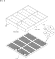
- FIG. 1 is a drawing illustrating a pack case according to the present invention
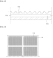
- FIG. 2 is a cross-sectional view of an incision along line "A-A" of FIG. 1 .
- the illustrated pack case 100 includes a base plate 110 forming a low surface, a side plate 120 surrounding a periphery of the base plate 110, a separation wall member 130 longitudinally and/or transversely disposed to divide an accommodated space bounded by the side plate 120, and a lid 160 closing an upper surface of the accommodated space.
- the base plate 110 is provided with a cooling channel 114 through which a cooling fluid is stored or flows.
- the base plate 110 is shown in FIG. 2 as being provided with the cooling channel 114, it is possible that a separate cooling plate (not shown) is bonded to the base plate 110.
- a plurality of engraved structures 112 are formed in each region in contact with the lower surface of the respective battery module 200.
- the plurality of engraved structures 112 may form a lattice structure that is uniformly arranged longitudinally with respect to the upper surface of the base plate 110, and the individual engraved structures 112 form an inwardly recessed space.
- the plurality of engraved structures 112 may be manufactured by applying any of the known processing technologies, such as pressing, mechanical cutting, plasma processing, electrolytic processing, etching, casting, and the like. Further, by the plurality of engraved structures 112, the engraved structures may protrude correspondingly into the inside of the base plate 110, but since this may adversely influence the flow of the cooling fluid flowing through the cooling channel 114, it may be desirable that the inner surface of the base plate 110 forming part of the cooling channel 114 has a flat surface.
- the plurality of engraved structures 112 formed on the upper surface of the base plate 110 form a space for accommodating thermal resin 300.
- a plurality of battery modules 200 are stored in the pack case 100 to complete as a battery pack 10, wherein the base plate 110 forming the bottom surface of the pack case 100 and the lower frame 222 of the module case 220 are in contact with each other to facilitate conduction heat transfer.
- the contact surface of the base plate 110 and the module case 220 is interposed with the thermal resin 300 having excellent thermal conductivity.
- the base plate 110 is often provided with heat dissipation means such as cooling channels 114. Therefore, it may be advantageous for suppressing or delaying heat propagation to increase the amount of heat dissipated outside the battery pack 10 by conducting the heat of the battery modules 200 in the pack case 100 to the base plate 110 as soon as possible, before the heat of the battery modules 200 in which thermal runaway occurs spreads by convective heat transfer to a side other than the base plate 110.
- FIG. 2 is a cross-sectional view through an incision along line "A-A" of FIG. 1 , and as shown, the thermal resin 300 filled within the recessed engraved structures 112 has the effect of increasing the heat transfer area from the battery module 200 to the base plate 110 compared to a flat contact surface.
- the amount of heat conducted from the battery module 200 to the base plate 110 is proportionally increased, thereby allowing the heat of the battery module 200, which has generated thermal runaway, to be transferred to the base plate 110 as soon as possible and to have a chance to dissipate to the outside of the battery pack 10.
- the plurality of engraved structures 112 formed on the upper surface of the base plate 110 contributes to suppressing or delaying heat propagation, mediated by the thermal resin 300.
- the engraved structure 112 has a curved surface including a hemispherical surface and a semi-elliptical surface. This is in consideration of the fact that curved surfaces are an advantageous surface shape for expanding the heat transfer area.
- the engraved structure 112 may form a honeycomb structure. While the honeycomb structure may be somewhat lower than the case of FIG. 2 in terms of expanding the heat transfer area, it may be effective in compensating for or strengthening the support stiffness of the base plate 110, which may be weakened by the engraved structure 112.
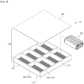
- FIG. 4 is a drawing illustrating a battery pack 10 according to the present invention. Although a single battery module 200 is illustratively shown in FIG. 4 , there is one battery module 200 for each individual accommodated space divided by the separation wall members 130.
- the battery module 200 includes a plurality of battery cells 210, and a module case 220 that accommodates the plurality of battery cells 210.
- the battery module 200 may further include parts such as insulation material for insulation between the battery cells 210, a busbar frame assembly (BFA) for electrical connection and external output between the plurality of battery cells 210, and the like, but since these parts are not directly related to the heat dissipation design of the pack case 100 according to the present invention, a description of thereto will be omitted.
- BFA busbar frame assembly
- the pack case 100 shown includes a base plate 110 forming a low surface, a side plate 120 surrounding a periphery of the base plate 110, a separation wall member 130 longitudinally and/or transversely disposed to divide an accommodated space limited by the side plate 120, and a lid 160 closing an upper surface of the accommodated space.
- the base plate 110 is provided with a cooling channel 114 in which a cooling fluid is stored or flows.
- the cooling channel 114 is shown in FIGS. 2 and 5 as being provided in the base plate 110, it is possible to organize the cooling channel 114 as a structure in which a separate cooling plate (not shown) is bonded to the base plate 110.
- the separation wall member 130 may be further distinguished by a longitudinal center beam 140 that crosses the center of the pack case 100, bisecting the internal accommodated space from side to side, and transverse cross beams 150 that intersect to form a lattice with respect to the center beam 140, depending on their disposition direction with respect to the base plate 110.
- FIG. 5 is a cross-sectional view illustrating a contact surface of the battery module 200 and the base plate 110.
- the battery pack 10 of FIG. 5 includes thermal resin 300 that is applied between the lower frame 222 of the battery module 200 and the base plate 110 of the pack case 100. Accordingly, all of the engraved structures 112 on the top surface of the base plate 110 are filled with the thermal resin 300.
- FIG. 6 is a diagram illustrating a conduction heat transfer path in the battery pack 10 of FIG. 5 . Assuming that the depicted battery module 200 is subjected to thermal runaway, a large amount of the heat generated by the thermal runaway is transferred to the base plate 110 in the form of conduction heat transfer as the heat transfer area is increased by the engraved structure 112.
- a large amount of the heat transferred to the base plate 110 is dissipated through the base plate 110 and out of the battery pack 10 through the cooling fluid, thereby reducing the amount of heat conducted to other battery modules 200 in the vicinity using the base plate 110 as a heat conduction medium. This improvement in heat dissipation contributes to inhibiting and delaying heat propagation within the battery pack 10.
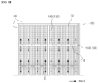
- FIG. 7 is a drawing illustrating an alternative embodiment of the pack case 100.
- the pack case 100 includes a separation wall member 130 that divides a plurality of battery modules 200 from each other, meanwhile, the base plate 110 includes a through-formed slot 116 in a region in contact with the separation wall member 130.
- the through-formed slot 116 in the base plate 110 is intended to limit conduction heat transfer across the underside of the separation wall member 130.
- the separation wall members 130 forming the center beam 140 and/or the cross beam 150 form a boundary between the battery modules 200, and the conduction heat transfer propagating across the separation wall members 130 to the adjacent battery modules 200 is limited by the slots 116 formed through the base plate 110.
- a portion of the heat conduction path between the battery modules 200 through the base plate 110 is physically eliminated by the slots 116 penetrating the base plate 110, thereby reducing and delaying excessive heat transfer caused by the battery modules 200 undergoing thermal runaway.
- the base plate 110 is provided with a cooling channel 114, the slot 116 structure needs to be formed by avoiding the cooling channel 114.
- the through slots 116 in the base plate 110 also serve to promote heat dissipation by convective heat transfer.
- conduction heat transfer propagating across the separation wall member 130 to the neighboring battery module 200 is restricted and delayed by the through-formed slots 116 in the base plate 110, thereby allowing more opportunity for heat dissipation from the base plate 110 to occur.
- the slots 116 disposed side-by-side with respect to the separation wall members 130 do not extend beyond the separation wall members 130.
- the slots 116 are formed through the base plate 110, which impacts the tightness of the pack case 100. Accordingly, the tightness of the pack case 100 may be achieved by designing the slots 116 to be sized such that the separation wall member 130 completely encloses the slots 116, such that the separation wall member 130 closes the slots 116 formed through the base plate 110.
- the slots 116 may be spaced apart along the separation wall member 130. Conduction heat transfer occurs into the region between the spaced apart slots 116, and the plurality of slots 116 being spaced apart, preferably evenly spaced apart, may be advantageous in preventing heat conducted to adjacent battery modules 200 from being locally concentrated and causing another thermal runaway.
Landscapes
- Chemical & Material Sciences (AREA)
- Chemical Kinetics & Catalysis (AREA)
- Electrochemistry (AREA)
- General Chemical & Material Sciences (AREA)
- Engineering & Computer Science (AREA)
- Manufacturing & Machinery (AREA)
- Secondary Cells (AREA)
- Battery Mounting, Suspending (AREA)
Abstract
Description
- This application claims the benefit of priority based on
Korean Patent Application No. 10-2023-0026639, filed on February 28, 2023 - The present invention relates to a pack case that improves the heat dissipation performance of a battery pack by facilitating conduction heat transfer from a battery module to a pack case.
- Secondary batteries, unlike primary batteries, are rechargeable and have been widely researched and developed in recent years due to the potential for miniaturization and large capacity. The demand for secondary batteries as an energy source is increasing rapidly due to the increasing technological development and demand for mobile devices, as well as electric vehicles and energy storage systems that are emerging in response to environmental protection needs.
- Secondary batteries are categorized into coin type batteries, cylindrical batteries, prismatic batteries, and pouch type batteries according to the shape of the battery case. In a secondary battery, an electrode assembly mounted inside the battery case is a chargeable and dischargeable power generating device comprising a stacked structure of electrodes and separators.
- Since secondary batteries are demanded to be used continuously for a long period of time, it is necessary to effectively control the heat generated during the charging and discharging process. If the secondary battery is not properly cooled, the increase in temperature will cause an increase in current, which will again cause an increase in temperature, which will cause a chain reaction, eventually leading to the catastrophic condition of thermal runaway.
- In addition, if the secondary batteries are grouped in the form of modules or packs, thermal runaway caused by one secondary battery will cause the other secondary batteries in the vicinity to continuously overheat, resulting in the phenomenon of thermal propagation. In other words, when a thermal runaway occurs in a battery module in a battery pack, a large amount of conductive dust, gas, and flame are emitted from the high-voltage terminals of the battery module, which causes dust to accumulate on the high-voltage terminals of other neighboring battery modules and triggers the phenomenon of thermal propagation by heat transfer by gas and flame.
- A design for preventing or delaying heat transfer of high heat from a battery cell or module that has undergone thermal runaway to neighboring battery cells or modules, comprising an insulation design that uses an insulation material to prevent or delay heat transfer from a battery module that has undergone thermal runaway to neighboring battery modules, and a heat dissipation design that initially and rapidly dissipates heat from a battery module that has undergone thermal runaway to the outside of the battery pack to reduce heat transfer to neighboring battery modules.
- The prevention and delay of thermal runaway is a critical issue, especially in electric vehicles, where it can lead to life-threatening accidents, and laws and regulations are becoming increasingly strict. In other words, they require a sufficient delay time before the thermal runaway phenomenon spreads to allow time for emergency evacuation and safety measures. Therefore, there is a need for more effective measures to suppress or delay the occurrence of heat transfer in battery packs.
- The present invention is directed to providing a battery module in which the heat generated by a battery module that has generated a thermal runaway can be quickly transferred to a pack case in the form of conduction heat transfer in order to suppress and delay the heat propagation, and thereby be quickly released to the outside as convection heat transfer in the pack case.
- However, the technical problem to be solved by the present invention is not limited to the above-described problem, and other problems not mentioned can be clearly understood by a person skilled in the art from the description of the invention described below.
- The present invention relates to a pack case comprising a space for accommodating at least one battery module, in one example, a plurality of engraved structures is formed on an upper surface of a base plate in contact support of a lower surface of the battery module, and the plurality of engraved structures forming a space for accommodating thermal resin.
- In one embodiment of the present invention, the engraved structures may form a lattice structure uniformly arranged longitudinally with respect to the upper surface of the base plate.
- The engraved structure may increase the heat transfer area of the battery module with respect to the thermal resin to be filled therein compared to a plane.
- In an exemplary embodiment, the engraved structure may form a curved surface including a hemispherical surface and a semi-elliptical surface.
- Alternatively, the engraved structure may form a honeycomb structure.
- Meanwhile, the present invention provides a battery module comprising a plurality of battery cells, and a module case accommodated the plurality of battery cells, and a pack case having the above configuration, and including thermal resin applied between a lower frame of the battery module and a base plate of the pack case, and the thermal resin is filled in a plurality of engraved structures formed on an upper surface of the base plate.
- The battery pack of the present invention, through the thermal resin filled in the engraved structures, the conduction heat transfer area of the base plate with respect to the lower frame of the battery module is increased compared to a flat contact.
- Further, the battery pack of the present invention may comprise a pack case wherein the pack case includes a separation wall member dividing the plurality of battery modules from each other, and the base plate may comprise a slot formed through a region in contact with the separation wall member.
- In one embodiment, the slot may preferably not be exposed outside of the separation wall member.
- In addition, the slots may be spaced apart along the separation wall member in a plurality.
- The pack case of the present invention having the configuration as described above, wherein the engraved structure formed on the top surface of the base plate provides an expanded heat transfer area for the thermal resin, and the expanded heat-dissipating area provided by the engraved structure increases the amount of heat conducted from the battery module to the base plate, thereby allowing the heat of the battery module in which thermal runaway has occurred to be promptly transferred to the base plate and dissipated to the outside of the battery pack, thereby contributing to the suppression or delay of heat propagation.
- Further, the slot formed through the base plate along the separation wall member forming a boundary between the battery modules physically eliminates a portion of the heat conduction path between the battery modules, thereby reducing and delaying the excessive heat transfer caused by the battery module in which the thermal runaway occurs, as well as further promoting the heat dissipation in the base plate.
- However, the technical effects that can be obtained through the present invention is not limited to the above-described effects, and other effects not mentioned can be clearly understood by a person skilled in the art from the description of the invention described below.
- Because the following drawings attached to the present specification illustrate exemplary embodiments of the present invention and serve to facilitate understanding of the technical idea of the present invention together with the detailed description of the invention described below, the present invention should not be limitedly interpreted on the basis of the drawings.
-
FIG. 1 is a drawing illustrating a pack case according to the present invention. -
FIG. 2 is a cross-sectional view of an incision along line "A-A" ofFIG. 1 . -
FIG. 3 is a drawing illustrating another embodiment of an engraved structure provided on a base plate. -
FIG. 4 is a drawing illustrating a battery pack according to the present invention. -
FIG. 5 is a cross-sectional view illustrating a contact surface of the battery module and the base plate. -
FIG. 6 is a drawing illustrating a conduction heat transfer path in the battery pack ofFIG. 5 . -
FIG. 7 is a drawing illustrating another embodiment of the pack case. -
FIG. 8 is a drawing illustrating a conduction heat transfer path in the battery pack ofFIG. 7 . - The present invention may have various modifications and various embodiments, and thus specific embodiments thereof will be described in detail below.
- However, it should be understood that the present invention is not limited to the specific embodiments, and includes all modifications, equivalents, or alternatives within the spirit and technical scope of the present invention.
- The terms "comprise," "include," and "have" used herein designate the presence of characteristics, numbers, steps, actions, components, or members described in the specification or a combination thereof, and it should be understood that the possibility of the presence or addition of one or more other characteristics, numbers, steps, actions, components, members, or a combination thereof is not excluded in advance.
- In addition, in the present invention, when a part of a layer, film, region, plate, or the like is disposed "on" another part, this includes not only a case in which one part is disposed "directly on" another part, but a case in which still another part is interposed therebetween. In contrast, when a part of a layer, film, region, plate, or the like is disposed "under" another part, this includes not only a case in which one part is disposed "directly under" another part, but a case in which still another part is interposed therebetween. In addition, in the present application, "on" may include not only a case of being disposed on an upper portion but also a case of being disposed on a lower portion.
- The present invention relates to a pack case having a space for accommodating at least one battery module, in one example, a plurality of engraved structures is formed on an upper surface of a base plate that is in contact support of a lower surface of the battery module, wherein the plurality of engraved structures forms a space that accommodates thermal resin.
- Here, the engraved structure increases the heat transfer area of the battery module with respect to the thermal resin to be filled therein compared to a plane.
- Accordingly, the pack case of the present invention, from the viewpoint of heat dissipation design, through the increase of the heat transfer area for the thermal resin, can quickly transfer the heat generated in the battery module that has caused the thermal runaway to the pack case in the form of conduction heat transfer, and as a result, a large amount of heat is transferred to the pack case at an early stage, effectively suppressing or delaying the heat propagation within the battery pack as the amount of heat released to the outside as convection heat transfer increases.
- Hereinafter, specific embodiments of a
pack case 100 of the present invention will be described in detail with reference to the accompanying drawings. For reference, the directions of front, back, up, down, left, and right used in the following description to designate relative positions are for the purpose of understanding the invention and refer to the directions shown in the drawings unless otherwise specified. -
FIG. 1 is a drawing illustrating a pack case according to the present invention, andFIG. 2 is a cross-sectional view of an incision along line "A-A" ofFIG. 1 . - Referring to
FIGS. 1 and2 , the illustratedpack case 100 includes abase plate 110 forming a low surface, aside plate 120 surrounding a periphery of thebase plate 110, aseparation wall member 130 longitudinally and/or transversely disposed to divide an accommodated space bounded by theside plate 120, and alid 160 closing an upper surface of the accommodated space. Further, thebase plate 110 is provided with acooling channel 114 through which a cooling fluid is stored or flows. However, although thebase plate 110 is shown inFIG. 2 as being provided with thecooling channel 114, it is possible that a separate cooling plate (not shown) is bonded to thebase plate 110. - Referring to the upper surface of the
base plate 110 shown inFIGS. 1 and2 , a plurality of engravedstructures 112 are formed in each region in contact with the lower surface of therespective battery module 200. The plurality of engravedstructures 112 may form a lattice structure that is uniformly arranged longitudinally with respect to the upper surface of thebase plate 110, and the individual engravedstructures 112 form an inwardly recessed space. - The plurality of engraved
structures 112 may be manufactured by applying any of the known processing technologies, such as pressing, mechanical cutting, plasma processing, electrolytic processing, etching, casting, and the like. Further, by the plurality of engravedstructures 112, the engraved structures may protrude correspondingly into the inside of thebase plate 110, but since this may adversely influence the flow of the cooling fluid flowing through the coolingchannel 114, it may be desirable that the inner surface of thebase plate 110 forming part of thecooling channel 114 has a flat surface. - In the present invention, the plurality of engraved
structures 112 formed on the upper surface of thebase plate 110 form a space for accommodatingthermal resin 300. A plurality ofbattery modules 200 are stored in thepack case 100 to complete as abattery pack 10, wherein thebase plate 110 forming the bottom surface of thepack case 100 and the lower frame 222 of themodule case 220 are in contact with each other to facilitate conduction heat transfer. Moreover, in order to facilitate conduction heat transfer, the contact surface of thebase plate 110 and themodule case 220 is interposed with thethermal resin 300 having excellent thermal conductivity. - When thermal runaway occurs in any of the
battery modules 200 within thebattery pack 10, a large amount of heat is propagated to neighboringbattery modules 200 along thebase plate 110, where conduction heat transfer is actively occurring. Meanwhile, thebase plate 110 is often provided with heat dissipation means such ascooling channels 114. Therefore, it may be advantageous for suppressing or delaying heat propagation to increase the amount of heat dissipated outside thebattery pack 10 by conducting the heat of thebattery modules 200 in thepack case 100 to thebase plate 110 as soon as possible, before the heat of thebattery modules 200 in which thermal runaway occurs spreads by convective heat transfer to a side other than thebase plate 110. - From this view of heat dissipation, the plurality of engraved
structures 112 on the top surface of thebase plate 110 provides an expanded heat transfer area for thethermal resin 300.FIG. 2 is a cross-sectional view through an incision along line "A-A" ofFIG. 1 , and as shown, thethermal resin 300 filled within the recessedengraved structures 112 has the effect of increasing the heat transfer area from thebattery module 200 to thebase plate 110 compared to a flat contact surface. - Through the heat transfer area expanded by the engraved
structure 112, the amount of heat conducted from thebattery module 200 to thebase plate 110 is proportionally increased, thereby allowing the heat of thebattery module 200, which has generated thermal runaway, to be transferred to thebase plate 110 as soon as possible and to have a chance to dissipate to the outside of thebattery pack 10. Thus, the plurality of engravedstructures 112 formed on the upper surface of thebase plate 110 contributes to suppressing or delaying heat propagation, mediated by thethermal resin 300. - In the exemplary embodiment of
FIG. 2 , theengraved structure 112 has a curved surface including a hemispherical surface and a semi-elliptical surface. This is in consideration of the fact that curved surfaces are an advantageous surface shape for expanding the heat transfer area. Alternatively, as shown inFIG. 3 , theengraved structure 112 may form a honeycomb structure. While the honeycomb structure may be somewhat lower than the case ofFIG. 2 in terms of expanding the heat transfer area, it may be effective in compensating for or strengthening the support stiffness of thebase plate 110, which may be weakened by the engravedstructure 112. -
FIG. 4 is a drawing illustrating abattery pack 10 according to the present invention. Although asingle battery module 200 is illustratively shown inFIG. 4 , there is onebattery module 200 for each individual accommodated space divided by theseparation wall members 130. - The
battery module 200 includes a plurality ofbattery cells 210, and amodule case 220 that accommodates the plurality ofbattery cells 210. In addition, thebattery module 200 may further include parts such as insulation material for insulation between thebattery cells 210, a busbar frame assembly (BFA) for electrical connection and external output between the plurality ofbattery cells 210, and the like, but since these parts are not directly related to the heat dissipation design of thepack case 100 according to the present invention, a description of thereto will be omitted. - The
pack case 100 shown includes abase plate 110 forming a low surface, aside plate 120 surrounding a periphery of thebase plate 110, aseparation wall member 130 longitudinally and/or transversely disposed to divide an accommodated space limited by theside plate 120, and alid 160 closing an upper surface of the accommodated space. Further, thebase plate 110 is provided with acooling channel 114 in which a cooling fluid is stored or flows. However, although thecooling channel 114 is shown inFIGS. 2 and5 as being provided in thebase plate 110, it is possible to organize thecooling channel 114 as a structure in which a separate cooling plate (not shown) is bonded to thebase plate 110. - Here, the
separation wall member 130 may be further distinguished by alongitudinal center beam 140 that crosses the center of thepack case 100, bisecting the internal accommodated space from side to side, and transverse cross beams 150 that intersect to form a lattice with respect to thecenter beam 140, depending on their disposition direction with respect to thebase plate 110. -
FIG. 5 is a cross-sectional view illustrating a contact surface of thebattery module 200 and thebase plate 110. Thebattery pack 10 ofFIG. 5 includesthermal resin 300 that is applied between the lower frame 222 of thebattery module 200 and thebase plate 110 of thepack case 100. Accordingly, all of theengraved structures 112 on the top surface of thebase plate 110 are filled with thethermal resin 300. - As described in the first embodiment, the
engraved structure 112 provided on thebase plate 110 provides an expanded heat transfer area for thethermal resin 300, and by the expansion of the heat transfer area achieved on thebase plate 110, the amount of heat conducted from thebattery module 200 to thebase plate 110 is proportionally increased.FIG. 6 is a diagram illustrating a conduction heat transfer path in thebattery pack 10 ofFIG. 5 . Assuming that the depictedbattery module 200 is subjected to thermal runaway, a large amount of the heat generated by the thermal runaway is transferred to thebase plate 110 in the form of conduction heat transfer as the heat transfer area is increased by the engravedstructure 112. A large amount of the heat transferred to thebase plate 110 is dissipated through thebase plate 110 and out of thebattery pack 10 through the cooling fluid, thereby reducing the amount of heat conducted toother battery modules 200 in the vicinity using thebase plate 110 as a heat conduction medium. This improvement in heat dissipation contributes to inhibiting and delaying heat propagation within thebattery pack 10. -
FIG. 7 is a drawing illustrating an alternative embodiment of thepack case 100. In the embodiment of thepack case 100 illustrated inFIG. 7 , thepack case 100 includes aseparation wall member 130 that divides a plurality ofbattery modules 200 from each other, meanwhile, thebase plate 110 includes a through-formedslot 116 in a region in contact with theseparation wall member 130. The through-formedslot 116 in thebase plate 110 is intended to limit conduction heat transfer across the underside of theseparation wall member 130. - The
separation wall members 130 forming thecenter beam 140 and/or thecross beam 150 form a boundary between thebattery modules 200, and the conduction heat transfer propagating across theseparation wall members 130 to theadjacent battery modules 200 is limited by theslots 116 formed through thebase plate 110. In other words, as shown inFIG. 8 , a portion of the heat conduction path between thebattery modules 200 through thebase plate 110 is physically eliminated by theslots 116 penetrating thebase plate 110, thereby reducing and delaying excessive heat transfer caused by thebattery modules 200 undergoing thermal runaway. For reference, when thebase plate 110 is provided with acooling channel 114, theslot 116 structure needs to be formed by avoiding thecooling channel 114. - In another aspect, the through
slots 116 in thebase plate 110 also serve to promote heat dissipation by convective heat transfer. In other words, conduction heat transfer propagating across theseparation wall member 130 to the neighboringbattery module 200 is restricted and delayed by the through-formedslots 116 in thebase plate 110, thereby allowing more opportunity for heat dissipation from thebase plate 110 to occur. - In one embodiment, it may be desirable that the
slots 116 disposed side-by-side with respect to theseparation wall members 130 do not extend beyond theseparation wall members 130. To further limit conduction heat transfer, theslots 116 are formed through thebase plate 110, which impacts the tightness of thepack case 100. Accordingly, the tightness of thepack case 100 may be achieved by designing theslots 116 to be sized such that theseparation wall member 130 completely encloses theslots 116, such that theseparation wall member 130 closes theslots 116 formed through thebase plate 110. - Further, the
slots 116 may be spaced apart along theseparation wall member 130. Conduction heat transfer occurs into the region between the spaced apartslots 116, and the plurality ofslots 116 being spaced apart, preferably evenly spaced apart, may be advantageous in preventing heat conducted toadjacent battery modules 200 from being locally concentrated and causing another thermal runaway. - As above, the present invention has been described in more detail through the drawings and embodiments. However, since the configuration described in the drawings or embodiments described herein is merely one embodiment of the present invention and do not represent the overall technical spirit of the invention, it should be understood that the invention covers various equivalents, modifications, and substitutions at the time of filing of this application.
-
- 10: battery pack
- 100: pack case
- 110: base plate
- 112: engraved structure
- 114: cooling channel
- 116: slot
- 120: side plate
- 130: separation wall member
- 140: center beam
- 150: cross beam
- 160: lid
- 200: battery module
- 210: battery cell
- 220: module case
- 222: lower frame
- 300: thermal resin
Claims (10)
- A pack case, comprising:a space for accommodating at least one battery module,wherein a plurality of engraved structures are formed on an upper surface of a base plate of the pack case in contact support of a lower surface of the battery module, and the plurality of engraved structures forming a space for accommodating thermal resin.
- The pack case of claim 1, wherein the engraved structures form a lattice structure uniformly arranged longitudinally with respect to the upper surface of the base plate.
- The pack case of claim 1, wherein the engraved structure increases the heat transfer area of the battery module with respect to the thermal resin to be filled therein compared to a plane.
- The pack case of claim 1, wherein the engraved structure forms a curved surface including a hemispherical surface and a semi-elliptical surface.
- The pack case of claim 2, wherein the engraved structure forms a honeycomb structure.
- A battery pack, comprising: a battery module comprising a plurality of battery cells, and a module case accommodated the plurality of battery cells;the pack case according to any one claim among claim 1 to claim 5, andthe thermal resin applied between a lower frame of the battery module and the base plate of the pack case,wherein the thermal resin is filled in the plurality of engraved structures formed on the upper surface of the base plate.
- The battery pack of claim 6, wherein through the thermal resin filled in the engraved structures, the conduction heat transfer area of the base plate with respect to the lower frame of the battery module is increased compared to a flat contact.
- The battery pack of claim 6, wherein the pack case comprises a separation wall member dividing the plurality of battery modules from each other,
and the base plate comprises a slot formed through a region in contact with the separation wall member. - The battery pack of claim 8, wherein the slot is not exposed outside of the separation wall member.
- The battery pack of claim 8, wherein the slots are spaced apart along the separation wall member in a plurality.
Applications Claiming Priority (2)
| Application Number | Priority Date | Filing Date | Title |
|---|---|---|---|
| KR1020230026639A KR20240133100A (en) | 2023-02-28 | 2023-02-28 | Pack case having improved heat dissipation structure |
| PCT/KR2024/095436 WO2024181848A1 (en) | 2023-02-28 | 2024-02-26 | Pack case with improved heat dissipation structure |
Publications (3)
| Publication Number | Publication Date |
|---|---|
| EP4531178A1 true EP4531178A1 (en) | 2025-04-02 |
| EP4531178A4 EP4531178A4 (en) | 2025-07-02 |
| EP4531178B1 EP4531178B1 (en) | 2026-04-01 |
Family
ID=92590030
Family Applications (1)
| Application Number | Title | Priority Date | Filing Date |
|---|---|---|---|
| EP24764247.3A Active EP4531178B1 (en) | 2023-02-28 | 2024-02-26 | Pack case with improved heat-dissipation structure |
Country Status (5)
| Country | Link |
|---|---|
| EP (1) | EP4531178B1 (en) |
| JP (1) | JP7818108B2 (en) |
| KR (1) | KR20240133100A (en) |
| CN (1) | CN119452511A (en) |
| WO (1) | WO2024181848A1 (en) |
Family Cites Families (13)
| Publication number | Priority date | Publication date | Assignee | Title |
|---|---|---|---|---|
| KR102112716B1 (en) | 2016-03-16 | 2020-05-19 | 주식회사 엘지화학 | Battery module, battery pack the battery module and vehicle comprising the battery pack |
| CN108886121B (en) * | 2016-04-01 | 2021-11-30 | 株式会社Lg化学 | Battery module |
| JP7281673B2 (en) | 2018-01-31 | 2023-05-26 | パナソニックIpマネジメント株式会社 | battery pack |
| KR102523702B1 (en) | 2018-07-03 | 2023-04-19 | 주식회사 엘지에너지솔루션 | Battery module |
| WO2020013120A1 (en) | 2018-07-09 | 2020-01-16 | 三洋電機株式会社 | Battery system, electric vehicle equipped with battery system, and electricity storage device |
| KR102663019B1 (en) * | 2018-07-25 | 2024-05-07 | 삼성에스디아이 주식회사 | Battery pack |
| KR102366268B1 (en) * | 2019-01-10 | 2022-02-21 | 주식회사 엘지에너지솔루션 | Battery Pack Having Insulation Tube |
| KR102228611B1 (en) * | 2019-02-13 | 2021-03-16 | 주식회사 세광정밀 | Bolt-coupled type water-cooled battery pack cooling device |
| KR102396438B1 (en) * | 2019-02-21 | 2022-05-10 | 주식회사 엘지에너지솔루션 | Battery module and method of manufacturing the same |
| KR102824434B1 (en) | 2020-01-16 | 2025-06-23 | 주식회사 엘지에너지솔루션 | Battery module and battery pack including the same |
| KR102411971B1 (en) * | 2020-11-04 | 2022-06-23 | 주식회사 성우하이텍 | Battery module cooling case and battery module including the same |
| KR20230020894A (en) * | 2021-08-04 | 2023-02-13 | 주식회사 엘지에너지솔루션 | Battery pack and vehicle including the same |
| KR102652015B1 (en) | 2021-08-18 | 2024-03-26 | 김영민 | Method for producing fermented rice cake with natural bean powder |
-
2023
- 2023-02-28 KR KR1020230026639A patent/KR20240133100A/en active Pending
-
2024
- 2024-02-26 CN CN202480003101.6A patent/CN119452511A/en active Pending
- 2024-02-26 WO PCT/KR2024/095436 patent/WO2024181848A1/en not_active Ceased
- 2024-02-26 JP JP2024575316A patent/JP7818108B2/en active Active
- 2024-02-26 EP EP24764247.3A patent/EP4531178B1/en active Active
Also Published As
| Publication number | Publication date |
|---|---|
| KR20240133100A (en) | 2024-09-04 |
| EP4531178B1 (en) | 2026-04-01 |
| JP2025522196A (en) | 2025-07-11 |
| EP4531178A4 (en) | 2025-07-02 |
| WO2024181848A1 (en) | 2024-09-06 |
| CN119452511A (en) | 2025-02-14 |
| JP7818108B2 (en) | 2026-02-19 |
Similar Documents
| Publication | Publication Date | Title |
|---|---|---|
| KR102814054B1 (en) | Bettery module | |
| JP7414990B2 (en) | Battery pack with battery module heat diffusion prevention structure applied | |
| KR20230131112A (en) | Battery module and battery pack including same | |
| KR102880677B1 (en) | Battery module and, battery pack and vehicle including same | |
| KR20220033931A (en) | A battery pack with thermal propagation prevention structure between battery modules | |
| KR20230020894A (en) | Battery pack and vehicle including the same | |
| KR20240084332A (en) | Battery pack having directional venting structure | |
| EP4531178B1 (en) | Pack case with improved heat-dissipation structure | |
| EP4567983A1 (en) | Battery module with improved heat dissipation structure | |
| JP2025539094A (en) | Battery pack | |
| KR20240098779A (en) | Battery pack suitable for thermal propagation delay | |
| EP4142020B1 (en) | Battery module and battery pack including the same | |
| KR20240166667A (en) | Battery Pack | |
| JP7776652B2 (en) | Battery pack with heat propagation delay structure | |
| KR20240131603A (en) | Wall structure of battery pack for delaying thermal propagation | |
| US20260135183A1 (en) | Battery Cell Assembly and Battery Pack Including the Same | |
| US20260081301A1 (en) | Battery module | |
| US20250253481A1 (en) | Battery module, battery pack, and vehicle including the same | |
| KR20230140044A (en) | Battery module | |
| KR20250064827A (en) | Battery pack | |
| KR20250157895A (en) | Battery cell assembly and battery pack including the same | |
| KR20250170365A (en) | Battery cell assembly and battery pack including the same | |
| JP2025103128A (en) | Battery Module | |
| KR20250118452A (en) | Battery pack and device including the same | |
| JP2026503306A (en) | Battery module and battery pack including same |
Legal Events
| Date | Code | Title | Description |
|---|---|---|---|
| STAA | Information on the status of an ep patent application or granted ep patent |
Free format text: STATUS: THE INTERNATIONAL PUBLICATION HAS BEEN MADE |
|
| PUAI | Public reference made under article 153(3) epc to a published international application that has entered the european phase |
Free format text: ORIGINAL CODE: 0009012 |
|
| STAA | Information on the status of an ep patent application or granted ep patent |
Free format text: STATUS: REQUEST FOR EXAMINATION WAS MADE |
|
| 17P | Request for examination filed |
Effective date: 20241227 |
|
| AK | Designated contracting states |
Kind code of ref document: A1 Designated state(s): AL AT BE BG CH CY CZ DE DK EE ES FI FR GB GR HR HU IE IS IT LI LT LU LV MC ME MK MT NL NO PL PT RO RS SE SI SK SM TR |
|
| REG | Reference to a national code |
Ref country code: DE Ref legal event code: R079 Free format text: PREVIOUS MAIN CLASS: H01M0050207000 Ipc: H01M0010655100 Ref country code: DE Ref legal event code: R079 Ref document number: 602024003662 Country of ref document: DE Free format text: PREVIOUS MAIN CLASS: H01M0050207000 Ipc: H01M0010655100 |
|
| A4 | Supplementary search report drawn up and despatched |
Effective date: 20250604 |
|
| RIC1 | Information provided on ipc code assigned before grant |
Ipc: H01M 10/653 20140101ALI20250528BHEP Ipc: H01M 50/289 20210101ALI20250528BHEP Ipc: H01M 50/207 20210101ALI20250528BHEP Ipc: H01M 10/6551 20140101AFI20250528BHEP |
|
| REG | Reference to a national code |
Ref country code: DE Ref legal event code: R079 Free format text: PREVIOUS MAIN CLASS: H01M0010655100 Ipc: H01M0010613000 Ref country code: DE Ref legal event code: R079 Ref document number: 602024003662 Country of ref document: DE Free format text: PREVIOUS MAIN CLASS: H01M0010655100 Ipc: H01M0010613000 |
|
| GRAP | Despatch of communication of intention to grant a patent |
Free format text: ORIGINAL CODE: EPIDOSNIGR1 |
|
| STAA | Information on the status of an ep patent application or granted ep patent |
Free format text: STATUS: GRANT OF PATENT IS INTENDED |
|
| RIC1 | Information provided on ipc code assigned before grant |
Ipc: H01M 10/613 20140101AFI20260112BHEP Ipc: H01M 10/625 20140101ALI20260112BHEP Ipc: H01M 10/643 20140101ALI20260112BHEP Ipc: H01M 10/653 20140101ALI20260112BHEP Ipc: H01M 10/6551 20140101ALI20260112BHEP Ipc: H01M 10/6554 20140101ALI20260112BHEP Ipc: H01M 10/6555 20140101ALI20260112BHEP Ipc: H01M 50/204 20210101ALI20260112BHEP Ipc: H01M 50/207 20210101ALI20260112BHEP Ipc: H01M 50/289 20210101ALI20260112BHEP |
|
| GRAS | Grant fee paid |
Free format text: ORIGINAL CODE: EPIDOSNIGR3 |
|
| INTG | Intention to grant announced |
Effective date: 20260126 |
|
| GRAA | (expected) grant |
Free format text: ORIGINAL CODE: 0009210 |
|
| STAA | Information on the status of an ep patent application or granted ep patent |
Free format text: STATUS: THE PATENT HAS BEEN GRANTED |
|
| P01 | Opt-out of the competence of the unified patent court (upc) registered |
Free format text: CASE NUMBER: UPC_APP_0003978_4531178/2026 Effective date: 20260203 |
|
| AK | Designated contracting states |
Kind code of ref document: B1 Designated state(s): AL AT BE BG CH CY CZ DE DK EE ES FI FR GB GR HR HU IE IS IT LI LT LU LV MC ME MK MT NL NO PL PT RO RS SE SI SK SM TR |
|
| DAV | Request for validation of the european patent (deleted) | ||
| DAX | Request for extension of the european patent (deleted) | ||
| REG | Reference to a national code |
Ref country code: CH Ref legal event code: F10 Free format text: ST27 STATUS EVENT CODE: U-0-0-F10-F00 (AS PROVIDED BY THE NATIONAL OFFICE) Effective date: 20260401 Ref country code: GB Ref legal event code: FG4D |
|
| REG | Reference to a national code |
Ref country code: IE Ref legal event code: FG4D |
|
| REG | Reference to a national code |
Ref country code: DE Ref legal event code: R096 Ref document number: 602024003662 Country of ref document: DE |