EP4531172A1 - Battery with perfected spacers between cells - Google Patents
Battery with perfected spacers between cells Download PDFInfo
- Publication number
- EP4531172A1 EP4531172A1 EP23306640.6A EP23306640A EP4531172A1 EP 4531172 A1 EP4531172 A1 EP 4531172A1 EP 23306640 A EP23306640 A EP 23306640A EP 4531172 A1 EP4531172 A1 EP 4531172A1
- Authority
- EP
- European Patent Office
- Prior art keywords
- spacer
- battery
- cells
- spacer element
- longitudinal direction
- Prior art date
- Legal status (The legal status is an assumption and is not a legal conclusion. Google has not performed a legal analysis and makes no representation as to the accuracy of the status listed.)
- Pending
Links
Images




Classifications
-
- H—ELECTRICITY
- H01—ELECTRIC ELEMENTS
- H01M—PROCESSES OR MEANS, e.g. BATTERIES, FOR THE DIRECT CONVERSION OF CHEMICAL ENERGY INTO ELECTRICAL ENERGY
- H01M50/00—Constructional details or processes of manufacture of the non-active parts of electrochemical cells other than fuel cells, e.g. hybrid cells
- H01M50/20—Mountings; Secondary casings or frames; Racks, modules or packs; Suspension devices; Shock absorbers; Transport or carrying devices; Holders
- H01M50/289—Mountings; Secondary casings or frames; Racks, modules or packs; Suspension devices; Shock absorbers; Transport or carrying devices; Holders characterised by spacing elements or positioning means within frames, racks or packs
- H01M50/291—Mountings; Secondary casings or frames; Racks, modules or packs; Suspension devices; Shock absorbers; Transport or carrying devices; Holders characterised by spacing elements or positioning means within frames, racks or packs characterised by their shape
-
- H—ELECTRICITY
- H01—ELECTRIC ELEMENTS
- H01M—PROCESSES OR MEANS, e.g. BATTERIES, FOR THE DIRECT CONVERSION OF CHEMICAL ENERGY INTO ELECTRICAL ENERGY
- H01M10/00—Secondary cells; Manufacture thereof
- H01M10/60—Heating or cooling; Temperature control
- H01M10/61—Types of temperature control
- H01M10/613—Cooling or keeping cold
-
- H—ELECTRICITY
- H01—ELECTRIC ELEMENTS
- H01M—PROCESSES OR MEANS, e.g. BATTERIES, FOR THE DIRECT CONVERSION OF CHEMICAL ENERGY INTO ELECTRICAL ENERGY
- H01M10/00—Secondary cells; Manufacture thereof
- H01M10/60—Heating or cooling; Temperature control
- H01M10/64—Heating or cooling; Temperature control characterised by the shape of the cells
- H01M10/647—Prismatic or flat cells, e.g. pouch cells
-
- H—ELECTRICITY
- H01—ELECTRIC ELEMENTS
- H01M—PROCESSES OR MEANS, e.g. BATTERIES, FOR THE DIRECT CONVERSION OF CHEMICAL ENERGY INTO ELECTRICAL ENERGY
- H01M10/00—Secondary cells; Manufacture thereof
- H01M10/60—Heating or cooling; Temperature control
- H01M10/65—Means for temperature control structurally associated with the cells
- H01M10/655—Solid structures for heat exchange or heat conduction
- H01M10/6556—Solid parts with flow channel passages or pipes for heat exchange
- H01M10/6557—Solid parts with flow channel passages or pipes for heat exchange arranged between the cells
-
- H—ELECTRICITY
- H01—ELECTRIC ELEMENTS
- H01M—PROCESSES OR MEANS, e.g. BATTERIES, FOR THE DIRECT CONVERSION OF CHEMICAL ENERGY INTO ELECTRICAL ENERGY
- H01M50/00—Constructional details or processes of manufacture of the non-active parts of electrochemical cells other than fuel cells, e.g. hybrid cells
- H01M50/20—Mountings; Secondary casings or frames; Racks, modules or packs; Suspension devices; Shock absorbers; Transport or carrying devices; Holders
- H01M50/204—Racks, modules or packs for multiple batteries or multiple cells
- H01M50/207—Racks, modules or packs for multiple batteries or multiple cells characterised by their shape
- H01M50/209—Racks, modules or packs for multiple batteries or multiple cells characterised by their shape adapted for prismatic or rectangular cells
-
- H—ELECTRICITY
- H01—ELECTRIC ELEMENTS
- H01M—PROCESSES OR MEANS, e.g. BATTERIES, FOR THE DIRECT CONVERSION OF CHEMICAL ENERGY INTO ELECTRICAL ENERGY
- H01M50/00—Constructional details or processes of manufacture of the non-active parts of electrochemical cells other than fuel cells, e.g. hybrid cells
- H01M50/20—Mountings; Secondary casings or frames; Racks, modules or packs; Suspension devices; Shock absorbers; Transport or carrying devices; Holders
- H01M50/233—Mountings; Secondary casings or frames; Racks, modules or packs; Suspension devices; Shock absorbers; Transport or carrying devices; Holders characterised by physical properties of casings or racks, e.g. dimensions
- H01M50/242—Mountings; Secondary casings or frames; Racks, modules or packs; Suspension devices; Shock absorbers; Transport or carrying devices; Holders characterised by physical properties of casings or racks, e.g. dimensions adapted for protecting batteries against vibrations, collision impact or swelling
-
- H—ELECTRICITY
- H01—ELECTRIC ELEMENTS
- H01M—PROCESSES OR MEANS, e.g. BATTERIES, FOR THE DIRECT CONVERSION OF CHEMICAL ENERGY INTO ELECTRICAL ENERGY
- H01M50/00—Constructional details or processes of manufacture of the non-active parts of electrochemical cells other than fuel cells, e.g. hybrid cells
- H01M50/20—Mountings; Secondary casings or frames; Racks, modules or packs; Suspension devices; Shock absorbers; Transport or carrying devices; Holders
- H01M50/289—Mountings; Secondary casings or frames; Racks, modules or packs; Suspension devices; Shock absorbers; Transport or carrying devices; Holders characterised by spacing elements or positioning means within frames, racks or packs
- H01M50/293—Mountings; Secondary casings or frames; Racks, modules or packs; Suspension devices; Shock absorbers; Transport or carrying devices; Holders characterised by spacing elements or positioning means within frames, racks or packs characterised by the material
-
- H—ELECTRICITY
- H01—ELECTRIC ELEMENTS
- H01M—PROCESSES OR MEANS, e.g. BATTERIES, FOR THE DIRECT CONVERSION OF CHEMICAL ENERGY INTO ELECTRICAL ENERGY
- H01M50/00—Constructional details or processes of manufacture of the non-active parts of electrochemical cells other than fuel cells, e.g. hybrid cells
- H01M50/20—Mountings; Secondary casings or frames; Racks, modules or packs; Suspension devices; Shock absorbers; Transport or carrying devices; Holders
- H01M50/233—Mountings; Secondary casings or frames; Racks, modules or packs; Suspension devices; Shock absorbers; Transport or carrying devices; Holders characterised by physical properties of casings or racks, e.g. dimensions
-
- Y—GENERAL TAGGING OF NEW TECHNOLOGICAL DEVELOPMENTS; GENERAL TAGGING OF CROSS-SECTIONAL TECHNOLOGIES SPANNING OVER SEVERAL SECTIONS OF THE IPC; TECHNICAL SUBJECTS COVERED BY FORMER USPC CROSS-REFERENCE ART COLLECTIONS [XRACs] AND DIGESTS
- Y02—TECHNOLOGIES OR APPLICATIONS FOR MITIGATION OR ADAPTATION AGAINST CLIMATE CHANGE
- Y02E—REDUCTION OF GREENHOUSE GAS [GHG] EMISSIONS, RELATED TO ENERGY GENERATION, TRANSMISSION OR DISTRIBUTION
- Y02E60/00—Enabling technologies; Technologies with a potential or indirect contribution to GHG emissions mitigation
- Y02E60/10—Energy storage using batteries
Definitions
- the present invention relates to a battery with perfected spacers between cells.
- a battery is already known from prior art, comprising a casing housing prismatic cells stacked in a longitudinal direction, and comprising spacers between the cells.
- a cooling fluid circulates through ducts in the spacers, and/or between the spacers and the cells.
- the cells may swell while aging, which compress the spacers and thus tends to close the ducts, reducing the cooling power of the spacers.
- the invention is intended to remedy to this drawback, by furnishing a battery guaranteeing a fluid passage between the cells even when the cells swell.
- a guaranteed fluid passage allows to safely design a battery with a proper cooling and no risk for thermal propagation between the cells.
- the invention relates to a battery comprising a casing housing prismatic cells stacked in a longitudinal direction, and comprising spacers between the cells, characterized in that:
- the transversal extension of the spacer is limited, it is easy to compress on the first length, then its stiffness increases when encountering the contact, ensuring a minimum duct.
- a battery according to the invention may comprise any of the following features, alone or in any possible combination.
- FIG 1 partially shows a battery 10 according to a first example of embodiment.
- the battery 10 comprises a casing 12 (shown on Figure 2 ), housing a plurality of cells 14 stacked in a longitudinal direction X.
- Figure 1 shows a pair of cells 14, but it comprises more of them.
- Cells 14 are prismatic cells, having a generally parallelepiped shape. Each cell 14 has two main faces 14a, two lateral faces 14b, an upper face 14c and a lower face 14d. Each lateral face 14b is arranged in front of a respective lateral wall of the casing 12, as shown on figure 2 .
- the main faces 14a have a bigger surface than the other faces.
- Each main face 14a is parallel to the plane YZ.
- Each lateral face 14b is parallel to the plane XZ.
- the upper face 14c and the lower face 14d are parallel to the plane XY.
- the battery 10 also comprises spacers 16 between the cells 14. More particularly, each pair of cells 14 has a spacer 16 between the cells 14 of this pair. Figures only show pair of cells 14.
- the spacer 16 is arranged between the main faces of the corresponding cells 14.
- Each spacer 16 comprises at least one spacer element 18 comprising a curved wall, the spacer element 18 being deformable when compressed in the longitudinal direction X while extending in the transverse direction Y. Such a compression is due to swelling of the cells 14 during their life.
- the curved shape of the wall allows such a deformation.
- each spacer element 18 in the transverse direction Y is free on a first length, then limited by a contact.
- the battery 10 comprises cooling fluid, the curved wall having two faces, each face being in contact with cooling fluid.
- the invention uses immersion technology to cool the cells 14.
- the spacer 16 comprises a plurality of spacer elements 18, each spacer element 18 being formed by a cylindrical tube extending in the third direction Z. This cylindrical shape forms said curved wall.
- the spacer elements 18 are arranged side by side in the transverse direction Y.
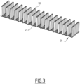
- the spacer elements 18 are connected at least at one of its ends by a flexible sheet 20, as shown on figure 3 .
- the sheets of all spacers 16 are connected together.
- the flexible sheet 20 comprises openings to allow the fluid to circulate.
- the flexible sheet 20 is made of a plurality of flexible elements 21 each extending between two adjacent spacer elements 18.
- the spacer elements 18 are preferentially made of rubber or plastic, for example by tridimensional printing or by molding.
- the spacer elements 18 are made of any material that is compatible with the temperatures and stresses, and chemically compatible with the fluid.
- metallic spacer elements 18 are suitable.
- the spacer elements 18 are arranged to encounter with each other when compressed, as shown on figure 2 .
- the distance between two adjacent spacer elements 18 is less than the radius of each spacer element 18.
- the distance between two adjacent spacer elements 18 is superior to ⁇ R 2 , where R is the radius of the spacer elements 18.
- the spacer elements 18 cannot extend in the transverse direction Y anymore, so their strength against compression is much more. As a result, the spacer elements 18 cannot be completely compressed, so there is still a cavity with cooling fluid in it, so there is no risk of too low fluid flow rate between the cells 14. This allows avoiding conductive heat transfer between two cells 14 through the spacer. Limited conductive heat transfer is preferred to avoid thermal propagation of a thermal runaway between two adjacent cells.
- At least one of the spacer elements 18 preferentially has a diameter that is different from the diameter of at least another of the spacer elements 18.
- at least one of the spacer elements 18 has a wall thickness that is different from the wall thickness of at least another of the spacer elements 18.
- the spacer stiffness is lower on the sides of the cell 14.
- the spacer elements 18 have a higher diameter and/or lower wall thickness on the side than on the center.
- each spacer element 18 is small regarding to the diameter of the spacer element 18, for example less than 20 % of the diameter. This ensure that neglectable conductive heat transfer will be achieved between two cells, in particular in the case of a safety event (thermal run away of a cell and risk of thermal propagation between cells).
- a battery 10 according to a second embodiment is shown on Figures 4 and 5 .
- the spacer 16 comprises only one spacer element 22, formed by a corrugated sheet.
- the spacer element 22 comprises a plurality of waves 24, aligned in the transverse direction Y. Each wave 24 forms said curved wall.
- the spacer element 22 is arranged to encounter with walls of the casing 12 when compressed.
- the length of the spacer element 22 in the transverse direction Y, when totally planed, is superior to the distance between the lateral walls of the casing.
- this spacer element 22 cannot extend in the transverse direction Y anymore, so its strength against compression is much more. As a result, the spacer element 22 cannot be completely compressed, so it still delimits a cavity with cooling fluid in it.
- At least one of the waves 24 has a height and/or a wall thickness that is different from the height and/or the wall thickness of at least another of the waves 24.
- the spacer stiffness is lower on the sides of the cell 14.
- the waves 24 have a lower height and/or wall thickness on the side than on the center.
- the waves 24 are, in a variant, bulged in the third direction, as shown on figure 6 .
- the invention uses spacers that are simple and cheap to manufacture.
Landscapes
- Chemical & Material Sciences (AREA)
- Chemical Kinetics & Catalysis (AREA)
- Electrochemistry (AREA)
- General Chemical & Material Sciences (AREA)
- Engineering & Computer Science (AREA)
- Manufacturing & Machinery (AREA)
- Secondary Cells (AREA)
- Battery Mounting, Suspending (AREA)
Abstract
Description
- The present invention relates to a battery with perfected spacers between cells.
- A battery is already known from prior art, comprising a casing housing prismatic cells stacked in a longitudinal direction, and comprising spacers between the cells. In order to cool the cells, a cooling fluid circulates through ducts in the spacers, and/or between the spacers and the cells.
- During the life of the cells, the cells may swell while aging, which compress the spacers and thus tends to close the ducts, reducing the cooling power of the spacers.
- The invention is intended to remedy to this drawback, by furnishing a battery guaranteeing a fluid passage between the cells even when the cells swell. A guaranteed fluid passage allows to safely design a battery with a proper cooling and no risk for thermal propagation between the cells.
- To this end, the invention relates to a battery comprising a casing housing prismatic cells stacked in a longitudinal direction, and comprising spacers between the cells, characterized in that:
- each spacer comprises at least one spacer element comprising a curved wall, the spacer element being deformable when compressed in the longitudinal direction while extending in a transverse direction perpendicular to the longitudinal direction,
- the extension of each spacer element in the transverse direction is free on a first length, then limited by a contact,
- the battery comprises cooling fluid, the curved wall having two faces, each face being in contact with cooling fluid.
- Because the transversal extension of the spacer is limited, it is easy to compress on the first length, then its stiffness increases when encountering the contact, ensuring a minimum duct.
- A battery according to the invention may comprise any of the following features, alone or in any possible combination.
- The spacer comprises a plurality of spacer elements, each spacer element being formed by a cylindrical tube extending in a third direction perpendicular to the longitudinal direction and perpendicular to the transverse direction, the spacer elements being arranged side by side in the transverse direction.
- The spacer elements are arranged to encounter with each other when compressed.
- At least one of the spacer elements has a diameter that is different from the diameter of at least another of the spacer elements.
- At least one of the spacer elements has a wall thickness that is different from the wall thickness of at least another of the spacer elements.
- The spacer comprises only one spacer element, formed by a corrugated sheet.
- The spacer element is arranged to encounter with lateral walls of the casing when compressed.
- The spacer element comprises a plurality of waves, at least one of the waves having a height and/or a wall thickness that is different from the height and/or the wall thickness of at least another of the waves.
- Several aspects and advantages of the invention will be enlightened in the following disclosure, given only as a non limitative example and made in reference to attached drawings in which:
-
Figure 1 is a perspective view of a partially shown battery according to a first embodiment of the invention; -
Figure 2 is a schematic view from above of a part of the battery of claim 1; -
Figure 3 is a perspective view of an assembly of spacers equipping the battery of claims 1 and 2; -
Figure 4 is a schematic view from above of a part of a battery according to a second embodiment of the invention; and -
Figure 5 is a similar view asFigure 4 of the part of the battery with swelled cells; -
Figure 6 is a side view of a spacer equipping the battery offigures 4 and5 . -
Figure 1 partially shows abattery 10 according to a first example of embodiment. Thebattery 10 comprises a casing 12 (shown onFigure 2 ), housing a plurality ofcells 14 stacked in a longitudinal direction X.Figure 1 shows a pair ofcells 14, but it comprises more of them. -
Cells 14 are prismatic cells, having a generally parallelepiped shape. Eachcell 14 has twomain faces 14a, twolateral faces 14b, anupper face 14c and alower face 14d. Eachlateral face 14b is arranged in front of a respective lateral wall of thecasing 12, as shown onfigure 2 . - We define on
Figure 1 a transverse direction Y perpendicular to the longitudinal direction X, and a third direction Z perpendicular to the transverse direction Y and perpendicular to the longitudinal direction X. We also define : - a plane YZ that is parallel to the transverse direction Y and to the third direction Z,
- a plane XZ that is parallel to the longitudinal direction X and to the third direction Z, and
- a plane XY that is parallel to the longitudinal direction X and to the transverse direction Y.
- The
main faces 14a have a bigger surface than the other faces. Eachmain face 14a is parallel to the plane YZ. - Each
lateral face 14b is parallel to the plane XZ. - The
upper face 14c and thelower face 14d are parallel to the plane XY. - The
battery 10 also comprisesspacers 16 between thecells 14. More particularly, each pair ofcells 14 has aspacer 16 between thecells 14 of this pair. Figures only show pair ofcells 14. - Only one
spacer 16 will be now disclosed, the other spacers being similar. - The
spacer 16 is arranged between the main faces of thecorresponding cells 14. - Each
spacer 16 comprises at least onespacer element 18 comprising a curved wall, thespacer element 18 being deformable when compressed in the longitudinal direction X while extending in the transverse direction Y. Such a compression is due to swelling of thecells 14 during their life. The curved shape of the wall allows such a deformation. - The extension of each
spacer element 18 in the transverse direction Y is free on a first length, then limited by a contact. - The
battery 10 comprises cooling fluid, the curved wall having two faces, each face being in contact with cooling fluid. In other words, the invention uses immersion technology to cool thecells 14. - In the first embodiment shown on
figures 1 and2 , thespacer 16 comprises a plurality ofspacer elements 18, eachspacer element 18 being formed by a cylindrical tube extending in the third direction Z. This cylindrical shape forms said curved wall. - The
spacer elements 18 are arranged side by side in the transverse direction Y. - Optionally, the
spacer elements 18 are connected at least at one of its ends by aflexible sheet 20, as shown onfigure 3 . Optionally, the sheets of allspacers 16 are connected together. Preferentially, theflexible sheet 20 comprises openings to allow the fluid to circulate. For example, theflexible sheet 20 is made of a plurality offlexible elements 21 each extending between twoadjacent spacer elements 18. - The
spacer elements 18 are preferentially made of rubber or plastic, for example by tridimensional printing or by molding. In a variant, thespacer elements 18 are made of any material that is compatible with the temperatures and stresses, and chemically compatible with the fluid. Thus,metallic spacer elements 18 are suitable. - The
spacer elements 18 are arranged to encounter with each other when compressed, as shown onfigure 2 . In particular, the distance between twoadjacent spacer elements 18 is less than the radius of eachspacer element 18. Preferentially, the distance between twoadjacent spacer elements 18 is superior to
spacer elements 18. - It should be noticed that, when compressed while not encountering each other, the
spacer elements 18 are compressed without significant resistive strength. - Then, when encountering each other, the
spacer elements 18 cannot extend in the transverse direction Y anymore, so their strength against compression is much more. As a result, thespacer elements 18 cannot be completely compressed, so there is still a cavity with cooling fluid in it, so there is no risk of too low fluid flow rate between thecells 14. This allows avoiding conductive heat transfer between twocells 14 through the spacer. Limited conductive heat transfer is preferred to avoid thermal propagation of a thermal runaway between two adjacent cells. - It should be noticed that the
cells 14 tend to bulge in the center when swollen. Thus, preferentially, the strength against compression is not the same on all the transversal length of thespacer 16. To this end, at least one of thespacer elements 18 preferentially has a diameter that is different from the diameter of at least another of thespacer elements 18. In a variant, or complementarily, at least one of thespacer elements 18 has a wall thickness that is different from the wall thickness of at least another of thespacer elements 18. - Preferentially, the spacer stiffness is lower on the sides of the
cell 14. Thus, thespacer elements 18 have a higher diameter and/or lower wall thickness on the side than on the center. - In a preferred embodiment, the wall thickness of each
spacer element 18 is small regarding to the diameter of thespacer element 18, for example less than 20 % of the diameter. This ensure that neglectable conductive heat transfer will be achieved between two cells, in particular in the case of a safety event (thermal run away of a cell and risk of thermal propagation between cells). - A
battery 10 according to a second embodiment is shown onFigures 4 and5 . - According to the second embodiment, the
spacer 16 comprises only onespacer element 22, formed by a corrugated sheet. Thus, thespacer element 22 comprises a plurality ofwaves 24, aligned in the transverse direction Y. Eachwave 24 forms said curved wall. - As shown on
Figure 5 , thespacer element 22 is arranged to encounter with walls of thecasing 12 when compressed. In other word, the length of thespacer element 22 in the transverse direction Y, when totally planed, is superior to the distance between the lateral walls of the casing. - Thus, when the
spacer element 22 encounters the lateral walls, thisspacer element 22 cannot extend in the transverse direction Y anymore, so its strength against compression is much more. As a result, thespacer element 22 cannot be completely compressed, so it still delimits a cavity with cooling fluid in it. - As previously said, the
cells 14 tend to bulge in the center when swollen. Thus, preferentially, the stiffness against compression is not the same on all the transversal length of thespacer 16. To this end, at least one of thewaves 24 has a height and/or a wall thickness that is different from the height and/or the wall thickness of at least another of thewaves 24. - Preferentially, the spacer stiffness is lower on the sides of the
cell 14. Thus, thewaves 24 have a lower height and/or wall thickness on the side than on the center. - In order to increase stiffness in the center, the
waves 24 are, in a variant, bulged in the third direction, as shown onfigure 6 . - It should be noticed that the invention uses spacers that are simple and cheap to manufacture.
-
- 10: Battery
- 12: Casing
- 14: Cell
- 14a: Main Faces of the cell
- 14b: Lateral faces of the cell
- 14c: Upper face of the cell
- 14d: Lower face of the cell
- 16: Spacer
- 18: Spacer element from the first embodiment
- 20: Flexible sheet
- 22: Spacer element from the second embodiment
- 24: Wave
- X: Longitudinal direction
- Y: Transverse direction
- Z: Third direction
Claims (8)
- A battery (10) comprising a casing (12) housing prismatic cells (14) stacked in a longitudinal direction (X), and comprising spacers (16) between the cells (14), characterized in that:- each spacer (16) comprises at least one spacer element (18; 22) comprising a curved wall, the spacer element (18; 22) being deformable when compressed in the longitudinal direction (X) while extending in a transverse direction (Y) perpendicular to the longitudinal direction (X),- the extension of each spacer element (18; 22) in the transverse direction (Y) is free on a first length, then limited by a contact,- the battery (10) comprises cooling fluid, the curved wall having two faces, each face being in contact with cooling fluid.
- The battery (10) according to claim 1, wherein the spacer (16) comprises a plurality of spacer elements (18), each spacer element (18) being formed by a cylindrical tube extending in a third direction (Z) perpendicular to the longitudinal direction (X) and perpendicular to the transverse direction (Y), the spacer elements (18) being arranged side by side in the transverse direction (Y).
- The battery (10) according to claim 2, wherein the spacer elements (18) are arranged to encounter with each other when compressed.
- The battery (10) according to claim 2 or 3, wherein at least one of the spacer elements (18) has a diameter that is different from the diameter of at least another of the spacer elements (18).
- The battery (10) according to any of claims 2 to 4, wherein at least one of the spacer elements (18; 22) has a wall thickness that is different from the wall thickness of at least another of the spacer elements (18).
- The battery (10) according to claim 1, wherein the spacer (16) comprises only one spacer element (22), formed by a corrugated sheet.
- The battery (10) according to claim 6, wherein the spacer element (22) is arranged to encounter with lateral walls of the casing (12) when compressed.
- The battery (10) according to claim 6 or 7, wherein the spacer element (22) comprises a plurality of waves (24), at least one of the waves (24) having a height and/or a wall thickness that is different from the height and/or the wall thickness of at least another of the waves (24).
Priority Applications (2)
| Application Number | Priority Date | Filing Date | Title |
|---|---|---|---|
| EP23306640.6A EP4531172A1 (en) | 2023-09-29 | 2023-09-29 | Battery with perfected spacers between cells |
| US18/894,915 US20250112318A1 (en) | 2023-09-29 | 2024-09-24 | Battery with perfected spacers between cells |
Applications Claiming Priority (1)
| Application Number | Priority Date | Filing Date | Title |
|---|---|---|---|
| EP23306640.6A EP4531172A1 (en) | 2023-09-29 | 2023-09-29 | Battery with perfected spacers between cells |
Publications (1)
| Publication Number | Publication Date |
|---|---|
| EP4531172A1 true EP4531172A1 (en) | 2025-04-02 |
Family
ID=88297277
Family Applications (1)
| Application Number | Title | Priority Date | Filing Date |
|---|---|---|---|
| EP23306640.6A Pending EP4531172A1 (en) | 2023-09-29 | 2023-09-29 | Battery with perfected spacers between cells |
Country Status (2)
| Country | Link |
|---|---|
| US (1) | US20250112318A1 (en) |
| EP (1) | EP4531172A1 (en) |
Citations (6)
| Publication number | Priority date | Publication date | Assignee | Title |
|---|---|---|---|---|
| US3866786A (en) * | 1972-09-22 | 1975-02-18 | Atomic Energy Commission | Energy absorbing structure in a steam generator |
| EP0817287A1 (en) * | 1996-01-17 | 1998-01-07 | Matsushita Electric Industrial Co., Ltd. | Battery container, battery, and layer-built battery |
| EP1117138A1 (en) * | 2000-01-12 | 2001-07-18 | Matsushita Electric Industrial Co., Ltd. | Modular prismatic battery with cooling structure |
| DE202016100629U1 (en) * | 2016-02-09 | 2016-02-18 | Ford Global Technologies, Llc | Inside, reinforced, cylindrical, shock-absorbing elements enclosed battery housing |
| US20160164061A1 (en) * | 2014-12-09 | 2016-06-09 | Samsung Sdi Co., Ltd. | Battery module |
| EP3193385A1 (en) * | 2016-01-12 | 2017-07-19 | Toyota Jidosha Kabushiki Kaisha | Battery pack |
-
2023
- 2023-09-29 EP EP23306640.6A patent/EP4531172A1/en active Pending
-
2024
- 2024-09-24 US US18/894,915 patent/US20250112318A1/en active Pending
Patent Citations (6)
| Publication number | Priority date | Publication date | Assignee | Title |
|---|---|---|---|---|
| US3866786A (en) * | 1972-09-22 | 1975-02-18 | Atomic Energy Commission | Energy absorbing structure in a steam generator |
| EP0817287A1 (en) * | 1996-01-17 | 1998-01-07 | Matsushita Electric Industrial Co., Ltd. | Battery container, battery, and layer-built battery |
| EP1117138A1 (en) * | 2000-01-12 | 2001-07-18 | Matsushita Electric Industrial Co., Ltd. | Modular prismatic battery with cooling structure |
| US20160164061A1 (en) * | 2014-12-09 | 2016-06-09 | Samsung Sdi Co., Ltd. | Battery module |
| EP3193385A1 (en) * | 2016-01-12 | 2017-07-19 | Toyota Jidosha Kabushiki Kaisha | Battery pack |
| DE202016100629U1 (en) * | 2016-02-09 | 2016-02-18 | Ford Global Technologies, Llc | Inside, reinforced, cylindrical, shock-absorbing elements enclosed battery housing |
Also Published As
| Publication number | Publication date |
|---|---|
| US20250112318A1 (en) | 2025-04-03 |
Similar Documents
| Publication | Publication Date | Title |
|---|---|---|
| CN110114933B (en) | Battery pack case and battery pack including the same | |
| CN108140774B (en) | Battery module including endplate with improved structure and endplate member therefor | |
| JP5737837B2 (en) | HEAT EXCHANGER AND VEHICLE AIR CONDITIONER INCLUDING THE SAME | |
| CN106233502B (en) | Battery module | |
| EP1701404B1 (en) | Battery module | |
| CN112290158B (en) | Electricity storage module | |
| US5787972A (en) | Compression tolerant louvered heat exchanger fin | |
| CN112133936A (en) | Frame body, cell frame for redox flow battery, and redox flow battery | |
| CN210744018U (en) | Connecting assembly, battery module, battery pack and device | |
| CN210136909U (en) | Temperature control assembly and battery pack | |
| JP6157813B2 (en) | Assembled battery | |
| KR20160069807A (en) | Battery module | |
| CN210744068U (en) | Connecting assemblies, battery modules, battery packs and devices | |
| US20250112318A1 (en) | Battery with perfected spacers between cells | |
| US20170012267A1 (en) | Energy storage apparatus and spacer | |
| CN115799706A (en) | Battery module | |
| CN118782959A (en) | Intermediate battery cell cooling element, battery device, motor vehicle and method for manufacturing intermediate battery cell cooling element | |
| CN222940005U (en) | Battery pack cooling structure, battery pack and vehicle | |
| EP4583250A1 (en) | Battery module, cooling plate, and battery pack | |
| EP4648183A1 (en) | Cell case for battery cell body | |
| CN115498310A (en) | battery pack | |
| JP7793458B2 (en) | Battery cushioning material | |
| CN115863839B (en) | Battery assembly and lithium ion battery | |
| US12451546B2 (en) | Power storage apparatus | |
| CN213799300U (en) | Battery pack and vehicle |
Legal Events
| Date | Code | Title | Description |
|---|---|---|---|
| PUAI | Public reference made under article 153(3) epc to a published international application that has entered the european phase |
Free format text: ORIGINAL CODE: 0009012 |
|
| STAA | Information on the status of an ep patent application or granted ep patent |
Free format text: STATUS: THE APPLICATION HAS BEEN PUBLISHED |
|
| AK | Designated contracting states |
Kind code of ref document: A1 Designated state(s): AL AT BE BG CH CY CZ DE DK EE ES FI FR GB GR HR HU IE IS IT LI LT LU LV MC ME MK MT NL NO PL PT RO RS SE SI SK SM TR |
|
| P01 | Opt-out of the competence of the unified patent court (upc) registered |
Free format text: CASE NUMBER: APP_16629/2025 Effective date: 20250405 |
|
| STAA | Information on the status of an ep patent application or granted ep patent |
Free format text: STATUS: REQUEST FOR EXAMINATION WAS MADE |
|
| 17P | Request for examination filed |
Effective date: 20250905 |