EP4531170A1 - Battery system with improved thermal resistance - Google Patents
Battery system with improved thermal resistance Download PDFInfo
- Publication number
- EP4531170A1 EP4531170A1 EP23200580.1A EP23200580A EP4531170A1 EP 4531170 A1 EP4531170 A1 EP 4531170A1 EP 23200580 A EP23200580 A EP 23200580A EP 4531170 A1 EP4531170 A1 EP 4531170A1
- Authority
- EP
- European Patent Office
- Prior art keywords
- cell
- battery
- sheathing
- venting
- battery cell
- Prior art date
- Legal status (The legal status is an assumption and is not a legal conclusion. Google has not performed a legal analysis and makes no representation as to the accuracy of the status listed.)
- Pending
Links
Images


Classifications
-
- H—ELECTRICITY
- H01—ELECTRIC ELEMENTS
- H01M—PROCESSES OR MEANS, e.g. BATTERIES, FOR THE DIRECT CONVERSION OF CHEMICAL ENERGY INTO ELECTRICAL ENERGY
- H01M50/00—Constructional details or processes of manufacture of the non-active parts of electrochemical cells other than fuel cells, e.g. hybrid cells
- H01M50/50—Current conducting connections for cells or batteries
- H01M50/543—Terminals
- H01M50/547—Terminals characterised by the disposition of the terminals on the cells
- H01M50/55—Terminals characterised by the disposition of the terminals on the cells on the same side of the cell
-
- H—ELECTRICITY
- H01—ELECTRIC ELEMENTS
- H01M—PROCESSES OR MEANS, e.g. BATTERIES, FOR THE DIRECT CONVERSION OF CHEMICAL ENERGY INTO ELECTRICAL ENERGY
- H01M50/00—Constructional details or processes of manufacture of the non-active parts of electrochemical cells other than fuel cells, e.g. hybrid cells
- H01M50/10—Primary casings; Jackets or wrappings
- H01M50/102—Primary casings; Jackets or wrappings characterised by their shape or physical structure
- H01M50/103—Primary casings; Jackets or wrappings characterised by their shape or physical structure prismatic or rectangular
-
- H—ELECTRICITY
- H01—ELECTRIC ELEMENTS
- H01M—PROCESSES OR MEANS, e.g. BATTERIES, FOR THE DIRECT CONVERSION OF CHEMICAL ENERGY INTO ELECTRICAL ENERGY
- H01M50/00—Constructional details or processes of manufacture of the non-active parts of electrochemical cells other than fuel cells, e.g. hybrid cells
- H01M50/10—Primary casings; Jackets or wrappings
- H01M50/131—Primary casings; Jackets or wrappings characterised by physical properties, e.g. gas permeability, size or heat resistance
-
- H—ELECTRICITY
- H01—ELECTRIC ELEMENTS
- H01M—PROCESSES OR MEANS, e.g. BATTERIES, FOR THE DIRECT CONVERSION OF CHEMICAL ENERGY INTO ELECTRICAL ENERGY
- H01M50/00—Constructional details or processes of manufacture of the non-active parts of electrochemical cells other than fuel cells, e.g. hybrid cells
- H01M50/20—Mountings; Secondary casings or frames; Racks, modules or packs; Suspension devices; Shock absorbers; Transport or carrying devices; Holders
- H01M50/271—Lids or covers for the racks or secondary casings
- H01M50/273—Lids or covers for the racks or secondary casings characterised by the material
- H01M50/28—Composite material consisting of a mixture of organic and inorganic materials
-
- H—ELECTRICITY
- H01—ELECTRIC ELEMENTS
- H01M—PROCESSES OR MEANS, e.g. BATTERIES, FOR THE DIRECT CONVERSION OF CHEMICAL ENERGY INTO ELECTRICAL ENERGY
- H01M10/00—Secondary cells; Manufacture thereof
- H01M10/60—Heating or cooling; Temperature control
- H01M10/62—Heating or cooling; Temperature control specially adapted for specific applications
- H01M10/625—Vehicles
-
- H—ELECTRICITY
- H01—ELECTRIC ELEMENTS
- H01M—PROCESSES OR MEANS, e.g. BATTERIES, FOR THE DIRECT CONVERSION OF CHEMICAL ENERGY INTO ELECTRICAL ENERGY
- H01M10/00—Secondary cells; Manufacture thereof
- H01M10/60—Heating or cooling; Temperature control
- H01M10/65—Means for temperature control structurally associated with the cells
- H01M10/653—Means for temperature control structurally associated with the cells characterised by electrically insulating or thermally conductive materials
-
- H—ELECTRICITY
- H01—ELECTRIC ELEMENTS
- H01M—PROCESSES OR MEANS, e.g. BATTERIES, FOR THE DIRECT CONVERSION OF CHEMICAL ENERGY INTO ELECTRICAL ENERGY
- H01M10/00—Secondary cells; Manufacture thereof
- H01M10/60—Heating or cooling; Temperature control
- H01M10/65—Means for temperature control structurally associated with the cells
- H01M10/658—Means for temperature control structurally associated with the cells by thermal insulation or shielding
-
- H—ELECTRICITY
- H01—ELECTRIC ELEMENTS
- H01M—PROCESSES OR MEANS, e.g. BATTERIES, FOR THE DIRECT CONVERSION OF CHEMICAL ENERGY INTO ELECTRICAL ENERGY
- H01M50/00—Constructional details or processes of manufacture of the non-active parts of electrochemical cells other than fuel cells, e.g. hybrid cells
- H01M50/10—Primary casings; Jackets or wrappings
- H01M50/102—Primary casings; Jackets or wrappings characterised by their shape or physical structure
- H01M50/107—Primary casings; Jackets or wrappings characterised by their shape or physical structure having curved cross-section, e.g. round or elliptic
-
- H—ELECTRICITY
- H01—ELECTRIC ELEMENTS
- H01M—PROCESSES OR MEANS, e.g. BATTERIES, FOR THE DIRECT CONVERSION OF CHEMICAL ENERGY INTO ELECTRICAL ENERGY
- H01M50/00—Constructional details or processes of manufacture of the non-active parts of electrochemical cells other than fuel cells, e.g. hybrid cells
- H01M50/10—Primary casings; Jackets or wrappings
- H01M50/116—Primary casings; Jackets or wrappings characterised by the material
- H01M50/117—Inorganic material
-
- H—ELECTRICITY
- H01—ELECTRIC ELEMENTS
- H01M—PROCESSES OR MEANS, e.g. BATTERIES, FOR THE DIRECT CONVERSION OF CHEMICAL ENERGY INTO ELECTRICAL ENERGY
- H01M50/00—Constructional details or processes of manufacture of the non-active parts of electrochemical cells other than fuel cells, e.g. hybrid cells
- H01M50/10—Primary casings; Jackets or wrappings
- H01M50/116—Primary casings; Jackets or wrappings characterised by the material
- H01M50/117—Inorganic material
- H01M50/119—Metals
-
- H—ELECTRICITY
- H01—ELECTRIC ELEMENTS
- H01M—PROCESSES OR MEANS, e.g. BATTERIES, FOR THE DIRECT CONVERSION OF CHEMICAL ENERGY INTO ELECTRICAL ENERGY
- H01M50/00—Constructional details or processes of manufacture of the non-active parts of electrochemical cells other than fuel cells, e.g. hybrid cells
- H01M50/10—Primary casings; Jackets or wrappings
- H01M50/116—Primary casings; Jackets or wrappings characterised by the material
- H01M50/121—Organic material
-
- H—ELECTRICITY
- H01—ELECTRIC ELEMENTS
- H01M—PROCESSES OR MEANS, e.g. BATTERIES, FOR THE DIRECT CONVERSION OF CHEMICAL ENERGY INTO ELECTRICAL ENERGY
- H01M50/00—Constructional details or processes of manufacture of the non-active parts of electrochemical cells other than fuel cells, e.g. hybrid cells
- H01M50/10—Primary casings; Jackets or wrappings
- H01M50/116—Primary casings; Jackets or wrappings characterised by the material
- H01M50/122—Composite material consisting of a mixture of organic and inorganic materials
-
- H—ELECTRICITY
- H01—ELECTRIC ELEMENTS
- H01M—PROCESSES OR MEANS, e.g. BATTERIES, FOR THE DIRECT CONVERSION OF CHEMICAL ENERGY INTO ELECTRICAL ENERGY
- H01M50/00—Constructional details or processes of manufacture of the non-active parts of electrochemical cells other than fuel cells, e.g. hybrid cells
- H01M50/10—Primary casings; Jackets or wrappings
- H01M50/116—Primary casings; Jackets or wrappings characterised by the material
- H01M50/124—Primary casings; Jackets or wrappings characterised by the material having a layered structure
- H01M50/1245—Primary casings; Jackets or wrappings characterised by the material having a layered structure characterised by the external coating on the casing
-
- H—ELECTRICITY
- H01—ELECTRIC ELEMENTS
- H01M—PROCESSES OR MEANS, e.g. BATTERIES, FOR THE DIRECT CONVERSION OF CHEMICAL ENERGY INTO ELECTRICAL ENERGY
- H01M50/00—Constructional details or processes of manufacture of the non-active parts of electrochemical cells other than fuel cells, e.g. hybrid cells
- H01M50/20—Mountings; Secondary casings or frames; Racks, modules or packs; Suspension devices; Shock absorbers; Transport or carrying devices; Holders
- H01M50/202—Casings or frames around the primary casing of a single cell or a single battery
-
- H—ELECTRICITY
- H01—ELECTRIC ELEMENTS
- H01M—PROCESSES OR MEANS, e.g. BATTERIES, FOR THE DIRECT CONVERSION OF CHEMICAL ENERGY INTO ELECTRICAL ENERGY
- H01M50/00—Constructional details or processes of manufacture of the non-active parts of electrochemical cells other than fuel cells, e.g. hybrid cells
- H01M50/20—Mountings; Secondary casings or frames; Racks, modules or packs; Suspension devices; Shock absorbers; Transport or carrying devices; Holders
- H01M50/204—Racks, modules or packs for multiple batteries or multiple cells
- H01M50/207—Racks, modules or packs for multiple batteries or multiple cells characterised by their shape
- H01M50/209—Racks, modules or packs for multiple batteries or multiple cells characterised by their shape adapted for prismatic or rectangular cells
-
- H—ELECTRICITY
- H01—ELECTRIC ELEMENTS
- H01M—PROCESSES OR MEANS, e.g. BATTERIES, FOR THE DIRECT CONVERSION OF CHEMICAL ENERGY INTO ELECTRICAL ENERGY
- H01M50/00—Constructional details or processes of manufacture of the non-active parts of electrochemical cells other than fuel cells, e.g. hybrid cells
- H01M50/20—Mountings; Secondary casings or frames; Racks, modules or packs; Suspension devices; Shock absorbers; Transport or carrying devices; Holders
- H01M50/218—Mountings; Secondary casings or frames; Racks, modules or packs; Suspension devices; Shock absorbers; Transport or carrying devices; Holders characterised by the material
- H01M50/22—Mountings; Secondary casings or frames; Racks, modules or packs; Suspension devices; Shock absorbers; Transport or carrying devices; Holders characterised by the material of the casings or racks
- H01M50/229—Composite material consisting of a mixture of organic and inorganic materials
-
- H—ELECTRICITY
- H01—ELECTRIC ELEMENTS
- H01M—PROCESSES OR MEANS, e.g. BATTERIES, FOR THE DIRECT CONVERSION OF CHEMICAL ENERGY INTO ELECTRICAL ENERGY
- H01M50/00—Constructional details or processes of manufacture of the non-active parts of electrochemical cells other than fuel cells, e.g. hybrid cells
- H01M50/20—Mountings; Secondary casings or frames; Racks, modules or packs; Suspension devices; Shock absorbers; Transport or carrying devices; Holders
- H01M50/249—Mountings; Secondary casings or frames; Racks, modules or packs; Suspension devices; Shock absorbers; Transport or carrying devices; Holders specially adapted for aircraft or vehicles, e.g. cars or trains
-
- H—ELECTRICITY
- H01—ELECTRIC ELEMENTS
- H01M—PROCESSES OR MEANS, e.g. BATTERIES, FOR THE DIRECT CONVERSION OF CHEMICAL ENERGY INTO ELECTRICAL ENERGY
- H01M50/00—Constructional details or processes of manufacture of the non-active parts of electrochemical cells other than fuel cells, e.g. hybrid cells
- H01M50/20—Mountings; Secondary casings or frames; Racks, modules or packs; Suspension devices; Shock absorbers; Transport or carrying devices; Holders
- H01M50/251—Mountings; Secondary casings or frames; Racks, modules or packs; Suspension devices; Shock absorbers; Transport or carrying devices; Holders specially adapted for stationary devices, e.g. power plant buffering or backup power supplies
-
- H—ELECTRICITY
- H01—ELECTRIC ELEMENTS
- H01M—PROCESSES OR MEANS, e.g. BATTERIES, FOR THE DIRECT CONVERSION OF CHEMICAL ENERGY INTO ELECTRICAL ENERGY
- H01M50/00—Constructional details or processes of manufacture of the non-active parts of electrochemical cells other than fuel cells, e.g. hybrid cells
- H01M50/20—Mountings; Secondary casings or frames; Racks, modules or packs; Suspension devices; Shock absorbers; Transport or carrying devices; Holders
- H01M50/296—Mountings; Secondary casings or frames; Racks, modules or packs; Suspension devices; Shock absorbers; Transport or carrying devices; Holders characterised by terminals of battery packs
-
- H—ELECTRICITY
- H01—ELECTRIC ELEMENTS
- H01M—PROCESSES OR MEANS, e.g. BATTERIES, FOR THE DIRECT CONVERSION OF CHEMICAL ENERGY INTO ELECTRICAL ENERGY
- H01M50/00—Constructional details or processes of manufacture of the non-active parts of electrochemical cells other than fuel cells, e.g. hybrid cells
- H01M50/30—Arrangements for facilitating escape of gases
-
- H—ELECTRICITY
- H01—ELECTRIC ELEMENTS
- H01M—PROCESSES OR MEANS, e.g. BATTERIES, FOR THE DIRECT CONVERSION OF CHEMICAL ENERGY INTO ELECTRICAL ENERGY
- H01M50/00—Constructional details or processes of manufacture of the non-active parts of electrochemical cells other than fuel cells, e.g. hybrid cells
- H01M50/30—Arrangements for facilitating escape of gases
- H01M50/342—Non-re-sealable arrangements
-
- H—ELECTRICITY
- H01—ELECTRIC ELEMENTS
- H01M—PROCESSES OR MEANS, e.g. BATTERIES, FOR THE DIRECT CONVERSION OF CHEMICAL ENERGY INTO ELECTRICAL ENERGY
- H01M50/00—Constructional details or processes of manufacture of the non-active parts of electrochemical cells other than fuel cells, e.g. hybrid cells
- H01M50/30—Arrangements for facilitating escape of gases
- H01M50/342—Non-re-sealable arrangements
- H01M50/3425—Non-re-sealable arrangements in the form of rupturable membranes or weakened parts, e.g. pierced with the aid of a sharp member
-
- H—ELECTRICITY
- H01—ELECTRIC ELEMENTS
- H01M—PROCESSES OR MEANS, e.g. BATTERIES, FOR THE DIRECT CONVERSION OF CHEMICAL ENERGY INTO ELECTRICAL ENERGY
- H01M50/00—Constructional details or processes of manufacture of the non-active parts of electrochemical cells other than fuel cells, e.g. hybrid cells
- H01M50/30—Arrangements for facilitating escape of gases
- H01M50/35—Gas exhaust passages comprising elongated, tortuous or labyrinth-shaped exhaust passages
- H01M50/367—Internal gas exhaust passages forming part of the battery cover or case; Double cover vent systems
-
- H—ELECTRICITY
- H01—ELECTRIC ELEMENTS
- H01M—PROCESSES OR MEANS, e.g. BATTERIES, FOR THE DIRECT CONVERSION OF CHEMICAL ENERGY INTO ELECTRICAL ENERGY
- H01M50/00—Constructional details or processes of manufacture of the non-active parts of electrochemical cells other than fuel cells, e.g. hybrid cells
- H01M50/30—Arrangements for facilitating escape of gases
- H01M50/383—Flame arresting or ignition-preventing means
-
- H—ELECTRICITY
- H01—ELECTRIC ELEMENTS
- H01M—PROCESSES OR MEANS, e.g. BATTERIES, FOR THE DIRECT CONVERSION OF CHEMICAL ENERGY INTO ELECTRICAL ENERGY
- H01M50/00—Constructional details or processes of manufacture of the non-active parts of electrochemical cells other than fuel cells, e.g. hybrid cells
- H01M50/30—Arrangements for facilitating escape of gases
- H01M50/394—Gas-pervious parts or elements
-
- H—ELECTRICITY
- H01—ELECTRIC ELEMENTS
- H01M—PROCESSES OR MEANS, e.g. BATTERIES, FOR THE DIRECT CONVERSION OF CHEMICAL ENERGY INTO ELECTRICAL ENERGY
- H01M50/00—Constructional details or processes of manufacture of the non-active parts of electrochemical cells other than fuel cells, e.g. hybrid cells
- H01M50/50—Current conducting connections for cells or batteries
- H01M50/543—Terminals
- H01M50/552—Terminals characterised by their shape
-
- H—ELECTRICITY
- H01—ELECTRIC ELEMENTS
- H01M—PROCESSES OR MEANS, e.g. BATTERIES, FOR THE DIRECT CONVERSION OF CHEMICAL ENERGY INTO ELECTRICAL ENERGY
- H01M2220/00—Batteries for particular applications
- H01M2220/10—Batteries in stationary systems, e.g. emergency power source in plant
-
- H—ELECTRICITY
- H01—ELECTRIC ELEMENTS
- H01M—PROCESSES OR MEANS, e.g. BATTERIES, FOR THE DIRECT CONVERSION OF CHEMICAL ENERGY INTO ELECTRICAL ENERGY
- H01M2220/00—Batteries for particular applications
- H01M2220/20—Batteries in motive systems, e.g. vehicle, ship, plane
-
- Y—GENERAL TAGGING OF NEW TECHNOLOGICAL DEVELOPMENTS; GENERAL TAGGING OF CROSS-SECTIONAL TECHNOLOGIES SPANNING OVER SEVERAL SECTIONS OF THE IPC; TECHNICAL SUBJECTS COVERED BY FORMER USPC CROSS-REFERENCE ART COLLECTIONS [XRACs] AND DIGESTS
- Y02—TECHNOLOGIES OR APPLICATIONS FOR MITIGATION OR ADAPTATION AGAINST CLIMATE CHANGE
- Y02E—REDUCTION OF GREENHOUSE GAS [GHG] EMISSIONS, RELATED TO ENERGY GENERATION, TRANSMISSION OR DISTRIBUTION
- Y02E60/00—Enabling technologies; Technologies with a potential or indirect contribution to GHG emissions mitigation
- Y02E60/10—Energy storage using batteries
Definitions
- an electric-vehicle battery, EVB, or traction battery is a battery used to power the propulsion of battery electric vehicles, BEVs.
- Electric-vehicle batteries differ from starting, lighting, and ignition batteries in that they are designed to provide power for sustained periods of time.
- a rechargeable (or secondary) battery differs from a primary battery in that it is designed to be repeatedly charged and discharged, while the latter is designed to provide only an irreversible conversion of chemical to electrical energy.
- Low-capacity rechargeable batteries are used as power supplies for small electronic devices, such as cellular phones, notebook computers and camcorders, while high-capacity rechargeable batteries are used as power supplies for electric and hybrid vehicles and the like.
- a rechargeable (or secondary) battery cell includes an electrode assembly including a positive electrode, a negative electrode, and a separator interposed between the positive and negative electrodes, a case receiving the electrode assembly, and an electrode terminal electrically connected to the electrode assembly.
- An electrolyte solution is injected into the case in order to enable charging and discharging of the battery cell via an electrochemical reaction of the positive electrode, the negative electrode, and the electrolyte solution.
- the shape of the case such as cylindrical or rectangular, may be selected based on the battery's intended purpose. Lithium-ion (and similar lithium polymer) batteries, widely known via their use in laptops and consumer electronics, dominate the most recent group of electric vehicles in development.
- Rechargeable batteries may be used as a battery module formed of a plurality of unit battery cells coupled to each other in series and/or in parallel so as to provide a high density such as for motor driving of a hybrid vehicle.
- the battery module may be formed by interconnecting the electrode terminals of the plurality of unit battery cells in an arrangement or configuration depending on a desired amount of power and in order to realize a high-power rechargeable battery.
- Battery modules can be constructed in either a block design or in a modular design.
- each battery is coupled to a common current collector structure and a common battery management system and the unit thereof is arranged in a housing.
- pluralities of battery cells are connected together to form submodules and several submodules are connected together to form the battery module.
- battery systems generally include of a plurality of battery modules connected in series for providing a desired voltage.
- the battery modules may include submodules with a plurality of stacked battery cells and each stack includes cells connected in parallel that are, in turn, connected in series ( XpYs ) or cells connected in series that are, in turn, connected in parallel (XsYp).
- a battery pack is a set of any number of (for example identical) battery modules.
- the battery modules may be configured in a series, parallel or a mixture of both to deliver the desired voltage, capacity, and/or power density.
- Components of a battery pack include the individual battery modules, and the interconnects, which provide electrical conductivity between the battery modules.
- a battery system may also include a battery management system (BMS), which is any suitable electronic system that is configured to manage the rechargeable battery cell, battery module, and battery pack, such as by protecting the batteries from operating outside their safe operating area, monitoring their states, calculating secondary data, reporting that data, controlling its environment, authenticating it and/or balancing it.
- BMS battery management system
- the BMS may monitor the state of the battery cell as represented by voltage (e.g., a total voltage of the battery pack or battery modules, and/or voltages of individual battery cells), temperature (e.g., an average temperature of the battery pack or battery modules, coolant intake temperature, coolant output temperature, or temperatures of individual battery cells), coolant flow (e.g., flow rate and/or cooling liquid pressure), and current.
- voltage e.g., a total voltage of the battery pack or battery modules, and/or voltages of individual battery cells
- temperature e.g., an average temperature of the battery pack or battery modules, coolant intake temperature, coolant output temperature, or temperatures of individual battery
- thermal runaway describes a process that accelerates due to increased temperature, in turn releasing energy that further increases temperature.
- Thermal runaway occurs in situations when an increase in temperature changes the conditions in a way that causes a further increase in temperature, often leading to a destructive result.
- thermal runaway is associated with strong exothermic reactions that are accelerated by temperature rise. These exothermic reactions include combustion of flammable gas compositions within the battery pack housing. For example, when a cell is heated above a critical temperature (typically above 150°C) the battery cell can transition into a thermal runaway.
- the initial heating may be caused by a local failure, such as a battery cell internal short circuit, heating from a defect electrical contact, short circuit to a neighboring battery cell.
- a failed battery cell i.e., a battery cell which has a local failure
- large quantities of hot gas are ejected from inside of the failed battery cell through the venting opening of the cell housing into the battery pack.
- the main components of the vented gas are H 2 , CO 2 , CO, electrolyte vapor and other hydrocarbons.
- the vented gas is therefore flammable and potentially toxic.
- the vented gas also causes a gas-pressure to increase inside the battery pack.
- Battery cells of a battery system may be insulated with plastic foils providing the required electrical insulation towards the side walls and bottom of a battery housing within normal operating temperatures of up to 150°C.
- the battery cells are squeezed or glued into the cell compartment of the battery housing towards the bottom and side walls, whereas the top side of the battery cells is usually uncovered.
- the plastic foils may melt with the consequence of loss of electrical insulation. This may result in a low electrical resistance between parts or components with high differential voltage (e.g. at least 20V) causing internal short circuits and/or arcing between these parts/components.
- the housings of the battery cells which usually consist of aluminum may be electrically conductive at such voltages so that the internal short circuits and/or arcing may occur between neighboring battery cells due to the loss of the electrical insulation between the battery cells.
- electrode terminals are arranged at the top side of the battery cell, wherein the cell sheathing includes openings for the electrode terminals to extend through.
- a battery system including a battery housing accommodating a plurality of battery cells according to the disclosure, the battery cells being arranged to form one or more battery packs and/or battery modules.
- the term “substantially,” “about,” and similar terms are used as terms of approximation and not as terms of degree, and are intended to account for the inherent deviations in measured or calculated values that would be recognized by those of ordinary skill in the art. Further, if the term “substantially” is used in combination with a feature that could be expressed using a numeric value, the term “substantially” denotes a range of +/-5% of the value centered on the value.
- the terms “upper” and “lower” are defined according to the z-axis.
- the upper cover is positioned at the upper part of the z-axis, whereas the lower cover is positioned at the lower part thereof.
- the sizes of elements may be exaggerated for clarity.
- the size or thickness of each element may be arbitrarily shown for illustrative purposes, and thus the embodiments of the present disclosure should not be construed as being limited thereto.
- a battery cell may form one of a plurality of battery cells of a traction battery of an electric vehicle.
- the battery cell includes a cell housing inside of which an electrochemical cell is arranged.
- the cell housing is a metal cell housing, i.e. the cell housing consists of metal or mainly includes metal.
- the metal cell housing may be an aluminum cell housing, i.e. the cell housing may consist of aluminum or be mainly included of aluminum.
- the metal cell housing is electrically conductive - at least at voltages that may occur during the regular operation of the battery cell as part of a traction battery of an electric vehicle, and/or at voltages that may occur during a thermal runaway occurring inside of the battery cell.
- the cell housing includes a top side, a bottom side and side walls.
- the cell housing may be prismatic, e.g. in the form of a cuboid.
- the cell housing may include six sides, i.e. the top side, the bottom side and four side walls.
- the cell housing (and thus the battery cell) may be cylindrical including two circular areas parallel to each other and a lateral surface connecting the two circular surfaces, wherein the side walls form the lateral surface of the cylinder.
- the lateral surface of the cylinder may be considered to form the side wall, one of the circular areas to form the top side and the other of the circular areas to form the bottom side of the cell housing.
- the battery cell includes at least one venting exit at a venting side of the battery cell, which may be the terminal side of the battery cells, i.e. the side that includes electrode terminals for electrically connecting the battery cell with further battery cells and/or with an electric motor of an electric vehicle.
- the venting exit is adapted to let a venting gas stream escape the battery cell during a thermal runaway of the battery cell.
- a venting valve may be arranged at the venting exit.
- the venting side may be the top side and/or the bottom side of the battery cell, i.e. a venting exit may be provided at the top side and/or the bottom side of the battery cell.
- the battery cell according to the invention includes a cell sheathing covering the outer surface of the cell housing.
- Covering means that the cell sheathing surrounds the cell housing, e.g. the whole cell housing, wherein the cell sheathing may be in direct contact with the outer surface of the cell housing.
- the cell sheathing sheathes or envelopes or encases the cell housing from the outside.
- the cell sheathing completely covers the outer surface of the cell housing.
- the whole outer surface of the cell housing may be covered by the cell sheathing.
- the venting exit of the battery cell and e.g. the electrode terminals of the battery cell, is/are not covered by the cell sheathing.
- the top side, the bottom and all of the side walls of the cell housing are covered by the cell sheathing.
- the top side, the bottom side and all of the four side walls may be (completely) covered by the cell sheathing.
- both circular surfaces and the lateral surface may be (completely) covered by the cell sheathing.
- the cell sheathing includes, or may consist of, a fiber mat embedded in a matrix support material, the combination of the fiber mat and the matrix support material thus forming a composite material.
- the fiber mat the fibers are not loosely arranged but are instead purposefully arranged.
- the fiber mat is a woven fabric, i.e. the fibers are woven or interlaced to form a fabric/mat.
- the matrix support material provides stability to the fiber mat.
- the cell sheathing includes, at the venting side, a venting opening aligned with the venting exit of the battery cell for letting the venting gas stream pass through the cell sheathing.
- the venting opening may be a cut-out in the cell sheathing.
- the venting opening may correspond in its form and size to the form and size of the venting exit it is aligned with.
- the venting opening may be a simple cut along a line. Such a cut may be sufficient to let the venting gas stream pass while the cell sheathing may still prevent contaminants from entering the battery cell through the venting exit from the outside.
- the cell sheathing may be fixed to the outer surface of the cell housing, for example via glue.
- the cell sheathing according to the invention provides a thermally stable electrical insulation to the battery cell by covering the outer surface of the cell housing.
- the cell sheathing provides an electrical and a thermal insulation.
- the battery cell is (electrically) insulated to all sides.
- the battery cell may be insulated against any neighboring battery cells.
- cell insulations as e.g. plastic foils melt during a thermal runway due to the high temperatures (1000° C and more) which results in loss of electrical insulation. This problem is overcome with the inventive cell sheathing because the cell sheathing may withstand these temperatures.
- the cell sheathing due to the composite material, provides an improved insulation specifically during a thermal runaway of the battery cell itself or a neighboring battery cell because while at the high temperatures occurring during a thermal runaway the matrix support material may get destroyed, the fiber mat may still maintain its structure and its electrical insulation properties.
- the composite material provides for the cell sheathing to be stable but still flexible which eases assembly. Nevertheless, albeit not being mechanically rigid, the cell sheathing provides sufficient electrical insulation and, may also provide sufficient thermal insulation such that thermal propagation of the thermal runaway to further battery cells is prevented.
- the cell sheathing according to the invention provides a heat resistant covering on an outside of the cell housing so that, in case of a thermal runaway, the cell housing and its electrical insulation stay intact.
- the battery cell may degas through its venting exit in a controlled manner due to the venting opening provided in the cell sheathing.
- the cell sheathing while covering the venting side (i.e. the top side or bottom side of the cell housing) nevertheless allows for the venting gas stream to exit the battery cell.
- the cell sheathing thus completely covers the outer surface of the battery cell, i.e. the top side, bottom side and any side walls, except for the venting exits, and possibly except for the electrode terminals as explained below.
- the cell sheathing may provide a thermal insulation of the battery cell e.g. by shielding the battery cell from any venting products which may deposit onto the cell sheathing from the outside.
- the battery cell according to the invention is thus capable of maintaining its electrical insulation during a thermal runaway and thus more securely handles the thermal runaway.
- the cell sheathing may provide a "one-piece" insulation with a tight fit to the cell housing.
- the battery cell includes electrode terminals, the electrode terminals being arranged at the top side of the battery cell, wherein the cell sheathing includes openings for the electrode terminals to extend through.
- the electrode terminals may also be named cell terminals.
- the electrode terminals are the electrical poles of the battery cell for accessing the electrical power stored within the electrochemical cell and for electrical connection of the battery cell with one or more other battery cells of a battery module/system.
- Neighboring battery cells may be interconnected with one another via electrical connecting means contacting the electrode terminals of the respective battery cells.
- the electrode terminals extend through the cell sheathing such that the cell sheathing does not cover the electrode terminals. Thus, the cell sheathing may completely cover the outer surface of the battery cell, i.e.
- the cell sheathing covering the complete outer surface of the cell housing provides an improved insulation specifically during a thermal runaway.
- the cell sheathing not covering the electrode terminals allows for an easy electrical connection of the electrode terminals with e.g. any further battery cells.
- the electrode terminals may, however, be covered by a cover element after the battery cell has been placed into a battery housing of a battery system along with further battery cells, i.e. after assembly of the battery system.
- the openings for the electrode terminals may be formed as cut-outs in the cell sheathing as this is simple to manufacture.
- the fiber mat includes one or more of the following: glass fibers, basalt fibers, mica fibers. These fibers may form a woven fabric as mentioned above. Mica means mica silicate minerals.
- the matrix support material may be or include a resin and/or a glue.
- the matrix support material may be or include an epoxy and/or polyurethane binder.
- the cell sheathing further includes a flame retardant.
- the flame retardant is activated by the high temperatures occurring during a thermal runaway and prevents or at least slows further heat propagation.
- the flame retardant further improves the capabilities of the cell sheathing to withstand the high temperatures occurring during a thermal runaway so that the cell sheathing is suited to provide for a reliable electrical insulation of the battery cell.
- the composite material of the cell sheathing is or includes an FR-4 composite material.
- FR-4 is a composite material composed of woven fiberglass fabric with an epoxy resin binder that is flame resistant (e.g. self-extinguishing) according to the National Electrical Manufacturers Association (NEMA) grade designation for glass-reinforced epoxy laminate material.
- NEMA National Electrical Manufacturers Association
- Such an FR-4 composite material is suited to withstand the high temperatures occurring during a thermal runaway and thus is suited to provide for a reliable electrical insulation of the battery cell.
- the cell sheathing is adapted to the contour of the outer surface of the cell housing including the top side, a bottom side and side walls. Being adapted to the contour means that the cell sheathing includes a shape corresponding to the shape of the elements it covers.
- the contour or form of the cell sheathing may be adapted to the contour of outer surface of the cell housing, i.e. the top side, bottom side, and all the side walls of the cell housing.
- the cell sheathing is suited for such an adaptation because it is relatively flexible due to the fiber mat but may still keep its form due to the matrix support material.
- Such an adaptation of the cell sheathing to the covered parts provides an improved electrical and thermal insulation. Also, this leaves less or no access for the venting products to reach the covered parts and thus allows for a reliable shielding.
Landscapes
- Chemical & Material Sciences (AREA)
- Chemical Kinetics & Catalysis (AREA)
- Electrochemistry (AREA)
- General Chemical & Material Sciences (AREA)
- Engineering & Computer Science (AREA)
- Inorganic Chemistry (AREA)
- Aviation & Aerospace Engineering (AREA)
- Composite Materials (AREA)
- Materials Engineering (AREA)
- Manufacturing & Machinery (AREA)
- Battery Mounting, Suspending (AREA)
Abstract
The present disclosure refers to a battery cell (10, 10'), including: a metal cell housing (12) with a top side (12a), a bottom side (12b) and side walls (12c), at the top side (12a) and/or at the bottom side (12b), a venting side (13) with a venting exit (14) to exit a venting gas stream from the battery cell (10, 10'), a cell sheathing (20) covering the outer surface of the cell housing (12) including the top side (12a), the bottom side (12b) and the side walls (12c), the cell sheathing (12) including a composite material with a fiber mat embedded in a matrix support material, wherein the cell sheathing (20) includes, at the venting side (13) of the battery cell (10, 10'), a venting opening (22) aligned with the venting exit (14) of the battery cell (10, 10') for letting the venting gas stream pass through the cell sheathing (20).
Description
- The present disclosure relates to a battery system which, due to an improved thermal resistance, more securely handles a thermal runaway of one or more of its battery cells. Further, the present invention relates to a vehicle including such a battery system.
- Recently, vehicles for transportation of goods and peoples have been developed that use electric power as a source for motion. Such an electric vehicle is an automobile that is propelled by an electric motor, using energy stored in rechargeable batteries. An electric vehicle may be solely powered by batteries or may be a form of hybrid vehicle powered by for example a gasoline generator or a hydrogen fuel power cell. A hybrid vehicle may include a combination of an electric motor and conventional combustion engine.
- Generally, an electric-vehicle battery, EVB, or traction battery is a battery used to power the propulsion of battery electric vehicles, BEVs. Electric-vehicle batteries differ from starting, lighting, and ignition batteries in that they are designed to provide power for sustained periods of time. A rechargeable (or secondary) battery differs from a primary battery in that it is designed to be repeatedly charged and discharged, while the latter is designed to provide only an irreversible conversion of chemical to electrical energy. Low-capacity rechargeable batteries are used as power supplies for small electronic devices, such as cellular phones, notebook computers and camcorders, while high-capacity rechargeable batteries are used as power supplies for electric and hybrid vehicles and the like.
- Generally, a rechargeable (or secondary) battery cell includes an electrode assembly including a positive electrode, a negative electrode, and a separator interposed between the positive and negative electrodes, a case receiving the electrode assembly, and an electrode terminal electrically connected to the electrode assembly. An electrolyte solution is injected into the case in order to enable charging and discharging of the battery cell via an electrochemical reaction of the positive electrode, the negative electrode, and the electrolyte solution. The shape of the case such as cylindrical or rectangular, may be selected based on the battery's intended purpose. Lithium-ion (and similar lithium polymer) batteries, widely known via their use in laptops and consumer electronics, dominate the most recent group of electric vehicles in development.
- Rechargeable batteries may be used as a battery module formed of a plurality of unit battery cells coupled to each other in series and/or in parallel so as to provide a high density such as for motor driving of a hybrid vehicle. For example, the battery module may be formed by interconnecting the electrode terminals of the plurality of unit battery cells in an arrangement or configuration depending on a desired amount of power and in order to realize a high-power rechargeable battery.
- Battery modules can be constructed in either a block design or in a modular design. In the block design each battery is coupled to a common current collector structure and a common battery management system and the unit thereof is arranged in a housing. In the modular design, pluralities of battery cells are connected together to form submodules and several submodules are connected together to form the battery module. In automotive applications, battery systems generally include of a plurality of battery modules connected in series for providing a desired voltage. The battery modules may include submodules with a plurality of stacked battery cells and each stack includes cells connected in parallel that are, in turn, connected in series (XpYs) or cells connected in series that are, in turn, connected in parallel (XsYp).
- A battery pack is a set of any number of (for example identical) battery modules. The battery modules may be configured in a series, parallel or a mixture of both to deliver the desired voltage, capacity, and/or power density. Components of a battery pack include the individual battery modules, and the interconnects, which provide electrical conductivity between the battery modules.
- A battery system may also include a battery management system (BMS), which is any suitable electronic system that is configured to manage the rechargeable battery cell, battery module, and battery pack, such as by protecting the batteries from operating outside their safe operating area, monitoring their states, calculating secondary data, reporting that data, controlling its environment, authenticating it and/or balancing it. For example, the BMS may monitor the state of the battery cell as represented by voltage (e.g., a total voltage of the battery pack or battery modules, and/or voltages of individual battery cells), temperature (e.g., an average temperature of the battery pack or battery modules, coolant intake temperature, coolant output temperature, or temperatures of individual battery cells), coolant flow (e.g., flow rate and/or cooling liquid pressure), and current. Additionally, the BMS may calculate values based on the above parameters, such as minimum and maximum cell voltage, state of charge (SOC) or depth of discharge (DOD) to indicate the charge level of the battery cell, state of health (SOH; a variously-defined measurement of the remaining capacity of the battery cell as % of the original capacity), state of power (SOP; the amount of power available for a defined time interval given the current power usage, temperature and other conditions), state of safety (SOS), maximum charge current as a charge current limit (CCL), maximum discharge current as a discharge current limit (DCL), and internal impedance of a cell (to determine open circuit voltage).
- The BMS may be centralized such that a single controller is connected to the battery cells through a multitude of wires. In other examples, the BMS may be also distributed, with a BMS board is installed at each cell, with just a single communication cable between the battery cell and a controller. In yet other examples, the BMS may have a modular construction including a few controllers, each handling a certain number of cells, while communicating between the controllers. Centralized BMSs are most economical, but are least expandable, and are plagued by a multitude of wires. Distributed BMSs are the most expensive, but are simplest to install, and offer the cleanest assembly. Modular BMSs provide a compromise of the features and problems of the other two topologies.
- The BMS may protect the battery pack from operating outside its safe operating area. Operation outside the safe operating area may be indicated by over-current, over-voltage (during charging), over-temperature, under-temperature, over-pressure, and ground fault or leakage current detection. The BMS may prevent the battery from operating outside its safe operating parameter by including an internal switch (e.g., a relay or solid-state device) that opens if the battery is operated outside its safe operating parameters, requesting the devices to which the battery is connected to reduce or even terminate using the battery, and actively controlling the environment, such as through heaters, fans, air conditioning or liquid cooling.
- To provide thermal control of the battery pack a thermal management system is required to safely use the at least one battery module by efficiently emitting, discharging and/or dissipating heat generated from its rechargeable batteries. If the heat emission/discharge/dissipation is not sufficiently performed, temperature deviations may occur between respective battery cells, such that the at least one battery module may no longer generate a desired (or designed) amount of power. In addition, an increase of the internal temperature can lead to abnormal reactions occurring therein and thus charging and discharging performance of the rechargeable battery deteriorates and the life-span of the rechargeable battery is shortened. Thus, cell cooling for effectively emitting/discharging/ dissipating heat from the cells is required.
- Exothermic decomposition of cell components may lead to a so-called thermal runaway. Generally, thermal runaway describes a process that accelerates due to increased temperature, in turn releasing energy that further increases temperature. Thermal runaway occurs in situations when an increase in temperature changes the conditions in a way that causes a further increase in temperature, often leading to a destructive result. In rechargeable battery systems, thermal runaway is associated with strong exothermic reactions that are accelerated by temperature rise. These exothermic reactions include combustion of flammable gas compositions within the battery pack housing. For example, when a cell is heated above a critical temperature (typically above 150°C) the battery cell can transition into a thermal runaway. The initial heating may be caused by a local failure, such as a battery cell internal short circuit, heating from a defect electrical contact, short circuit to a neighboring battery cell. During the thermal runaway, a failed battery cell, i.e., a battery cell which has a local failure, may reach a temperature exceeding 700°C. Further, large quantities of hot gas are ejected from inside of the failed battery cell through the venting opening of the cell housing into the battery pack. The main components of the vented gas are H2, CO2, CO, electrolyte vapor and other hydrocarbons. The vented gas is therefore flammable and potentially toxic. The vented gas also causes a gas-pressure to increase inside the battery pack.
- Battery cells of a battery system may be insulated with plastic foils providing the required electrical insulation towards the side walls and bottom of a battery housing within normal operating temperatures of up to 150°C. The battery cells are squeezed or glued into the cell compartment of the battery housing towards the bottom and side walls, whereas the top side of the battery cells is usually uncovered. During a heat-up of a damaged battery cell, caused e.g. by a thermal runaway inside the battery cell, the plastic foils may melt with the consequence of loss of electrical insulation. This may result in a low electrical resistance between parts or components with high differential voltage (e.g. at least 20V) causing internal short circuits and/or arcing between these parts/components. For example, the housings of the battery cells which usually consist of aluminum may be electrically conductive at such voltages so that the internal short circuits and/or arcing may occur between neighboring battery cells due to the loss of the electrical insulation between the battery cells.
- It is thus an object of the present invention to overcome or reduce at least some of the drawbacks of the prior art and to provide a battery cell which more securely handles a thermal runaway by preventing short circuits and/or arcing.
- The invention is defined by the appended claims. The description that follows is subjected to this limitation. Any disclosure lying outside the scope of the claims is only intended for illustrative as well as comparative purposes.
- According to an aspect of the present disclosure, a battery cell is provided, including: a metal cell housing with a top side, a bottom side and side walls, at the top side and/or at the bottom side, a venting side with a venting exit to exit a venting gas stream from the battery cell during a thermal runaway, a cell sheathing covering the outer surface of the cell housing including the top side, the bottom side and the side walls, the cell sheathing including a composite material with a fiber mat embedded in a matrix support material, wherein the cell sheathing includes, at the venting side of the battery cell, a venting opening aligned with the venting exit of the battery cell for letting the venting gas stream pass through the cell sheathing.
- According to an aspect of the present disclosure, electrode terminals are arranged at the top side of the battery cell, wherein the cell sheathing includes openings for the electrode terminals to extend through.
- According to an aspect of the present disclosure, the fiber mat includes glass fibers, basalt fibers and/or mica fibers.
- According to an aspect of the present disclosure, the matrix support material includes a resin and/or glue.
- According to an aspect of the present disclosure, the matrix support material includes an epoxy and/or polyurethane binder.
- According to an aspect of the present disclosure, the cell sheathing further includes a flame retardant.
- According to an aspect of the present disclosure, the composite material is an FR-4 composite material.
- According to an aspect of the present disclosure, the cell sheathing is adapted to the contour of the outer surface of the cell housing including the top side, a bottom side and side walls.
- According to an aspect of the present disclosure, a battery system is provided including a battery housing accommodating a plurality of battery cells according to the disclosure, the battery cells being arranged to form one or more battery packs and/or battery modules.
- According to an aspect of the present disclosure, an electric vehicle is provided including at least one battery cell according to the disclosure, or including the battery system according to the disclosure.
- Further aspects of the present disclosure could be learned from the dependent claims or the following description.
- Features will become apparent to those of ordinary skill in the art by describing in detail exemplary embodiments with reference to the attached drawings in which:
-
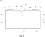
Fig. 1 illustrates a schematic sectional view of a battery cell according to a first embodiment. -
Fig. 2 illustrates a schematic top view of the battery cell ofFig. 1 . -
Fig. 3 illustrates a schematic sectional view of a battery cell according to a second embodiment - Reference will now be made in detail to embodiments, examples of which are illustrated in the accompanying drawings. Effects and features of the exemplary embodiments, and implementation methods thereof will be described with reference to the accompanying drawings. In the drawings, like reference numerals denote like elements, and redundant descriptions are omitted. The present disclosure, however, may be embodied in various different forms, and should not be construed as being limited to only the illustrated embodiments herein. Rather, these embodiments are provided as examples so that this disclosure will be thorough and complete, and will fully convey the aspects and features of the present disclosure to those skilled in the art.
- Accordingly, processes, elements, and techniques that are not considered necessary to those having ordinary skill in the art for a complete understanding of the aspects and features of the present disclosure may not be described. In the drawings, the relative sizes of elements, layers, and regions may be exaggerated for clarity.
- As used herein, the term "and/or" includes any and all combinations of one or more of the associated listed items. Further, the use of "may" when describing embodiments of the present disclosure refers to "one or more embodiments of the present disclosure." In the following description of embodiments of the present disclosure, the terms of a singular form may include plural forms unless the context clearly indicates otherwise.
- It will be understood that although the terms "first" and "second" are used to describe various elements, these elements should not be limited by these terms. These terms are only used to distinguish one element from another element. For example, a first element may be named a second element and, similarly, a second element may be named a first element, without departing from the scope of the present disclosure. As used herein, the term "and/or" includes any and all combinations of one or more of the associated listed items. Expressions such as "at least one of," when preceding a list of elements, modify the entire list of elements and do not modify the individual elements of the list.
- As used herein, the term "substantially," "about," and similar terms are used as terms of approximation and not as terms of degree, and are intended to account for the inherent deviations in measured or calculated values that would be recognized by those of ordinary skill in the art. Further, if the term "substantially" is used in combination with a feature that could be expressed using a numeric value, the term "substantially" denotes a range of +/-5% of the value centered on the value.
- It will be further understood that the terms "include," "comprise," "including," or "comprising" specify a property, a region, a fixed number, a step, a process, an element, a component, and a combination thereof but do not exclude other properties, regions, fixed numbers, steps, processes, elements, components, and combinations thereof.
- It will also be understood that when a film, a region, or an element is referred to as being "above" or "on" another film, region, or element, it can be directly on the other film, region, or element, or intervening films, regions, or elements may also be present.
- Herein, the terms "upper" and "lower" are defined according to the z-axis. For example, the upper cover is positioned at the upper part of the z-axis, whereas the lower cover is positioned at the lower part thereof. In the drawings, the sizes of elements may be exaggerated for clarity. For example, in the drawings, the size or thickness of each element may be arbitrarily shown for illustrative purposes, and thus the embodiments of the present disclosure should not be construed as being limited thereto.
- In the following description of embodiments of the present disclosure, the terms of a singular form may include plural forms unless the context clearly indicates otherwise.
- According to an aspect of the present disclosure, a battery cell is provided. The battery cell may form one of a plurality of battery cells of a traction battery of an electric vehicle. The battery cell includes a cell housing inside of which an electrochemical cell is arranged. The cell housing is a metal cell housing, i.e. the cell housing consists of metal or mainly includes metal. For example, the metal cell housing may be an aluminum cell housing, i.e. the cell housing may consist of aluminum or be mainly included of aluminum. The metal cell housing is electrically conductive - at least at voltages that may occur during the regular operation of the battery cell as part of a traction battery of an electric vehicle, and/or at voltages that may occur during a thermal runaway occurring inside of the battery cell.
- The cell housing includes a top side, a bottom side and side walls. The cell housing may be prismatic, e.g. in the form of a cuboid. In this case, the cell housing may include six sides, i.e. the top side, the bottom side and four side walls. Alternatively, the cell housing (and thus the battery cell) may be cylindrical including two circular areas parallel to each other and a lateral surface connecting the two circular surfaces, wherein the side walls form the lateral surface of the cylinder. In other words, in case of a cylindrical cell housing (and thus a cylindrical battery cell) the lateral surface of the cylinder may be considered to form the side wall, one of the circular areas to form the top side and the other of the circular areas to form the bottom side of the cell housing.
- The battery cell includes at least one venting exit at a venting side of the battery cell, which may be the terminal side of the battery cells, i.e. the side that includes electrode terminals for electrically connecting the battery cell with further battery cells and/or with an electric motor of an electric vehicle. The venting exit is adapted to let a venting gas stream escape the battery cell during a thermal runaway of the battery cell. A venting valve may be arranged at the venting exit. The venting side may be the top side and/or the bottom side of the battery cell, i.e. a venting exit may be provided at the top side and/or the bottom side of the battery cell.
- Further, the battery cell according to the invention includes a cell sheathing covering the outer surface of the cell housing. Covering means that the cell sheathing surrounds the cell housing, e.g. the whole cell housing, wherein the cell sheathing may be in direct contact with the outer surface of the cell housing. In other words, the cell sheathing sheathes or envelopes or encases the cell housing from the outside. In an embodiment, the cell sheathing completely covers the outer surface of the cell housing. In other words, the whole outer surface of the cell housing may be covered by the cell sheathing. Merely the venting exit of the battery cell, and e.g. the electrode terminals of the battery cell, is/are not covered by the cell sheathing. Thus, in an embodiment, the top side, the bottom and all of the side walls of the cell housing are covered by the cell sheathing. In case of a prismatic cell housing, the top side, the bottom side and all of the four side walls may be (completely) covered by the cell sheathing. In case of a cylindrical battery cell, both circular surfaces and the lateral surface may be (completely) covered by the cell sheathing.
- The cell sheathing includes, or may consist of, a fiber mat embedded in a matrix support material, the combination of the fiber mat and the matrix support material thus forming a composite material. Within the fiber mat the fibers are not loosely arranged but are instead purposefully arranged. For example, the fiber mat is a woven fabric, i.e. the fibers are woven or interlaced to form a fabric/mat. The matrix support material provides stability to the fiber mat. The cell sheathing includes, at the venting side, a venting opening aligned with the venting exit of the battery cell for letting the venting gas stream pass through the cell sheathing. The venting opening may be a cut-out in the cell sheathing. The venting opening may correspond in its form and size to the form and size of the venting exit it is aligned with. Also, the venting opening may be a simple cut along a line. Such a cut may be sufficient to let the venting gas stream pass while the cell sheathing may still prevent contaminants from entering the battery cell through the venting exit from the outside. The cell sheathing may be fixed to the outer surface of the cell housing, for example via glue.
- The cell sheathing according to the invention provides a thermally stable electrical insulation to the battery cell by covering the outer surface of the cell housing. The cell sheathing provides an electrical and a thermal insulation. As the cell sheathing surrounds the cell housing from all sides, the battery cell is (electrically) insulated to all sides. The battery cell may be insulated against any neighboring battery cells. As explained above, cell insulations as e.g. plastic foils melt during a thermal runway due to the high temperatures (1000° C and more) which results in loss of electrical insulation. This problem is overcome with the inventive cell sheathing because the cell sheathing may withstand these temperatures. The cell sheathing, due to the composite material, provides an improved insulation specifically during a thermal runaway of the battery cell itself or a neighboring battery cell because while at the high temperatures occurring during a thermal runaway the matrix support material may get destroyed, the fiber mat may still maintain its structure and its electrical insulation properties.
- The composite material provides for the cell sheathing to be stable but still flexible which eases assembly. Nevertheless, albeit not being mechanically rigid, the cell sheathing provides sufficient electrical insulation and, may also provide sufficient thermal insulation such that thermal propagation of the thermal runaway to further battery cells is prevented. Thus, the cell sheathing according to the invention provides a heat resistant covering on an outside of the cell housing so that, in case of a thermal runaway, the cell housing and its electrical insulation stay intact.
- The battery cell may degas through its venting exit in a controlled manner due to the venting opening provided in the cell sheathing. Thus, the cell sheathing, while covering the venting side (i.e. the top side or bottom side of the cell housing) nevertheless allows for the venting gas stream to exit the battery cell. The cell sheathing thus completely covers the outer surface of the battery cell, i.e. the top side, bottom side and any side walls, except for the venting exits, and possibly except for the electrode terminals as explained below. The cell sheathing may provide a thermal insulation of the battery cell e.g. by shielding the battery cell from any venting products which may deposit onto the cell sheathing from the outside. The battery cell according to the invention is thus capable of maintaining its electrical insulation during a thermal runaway and thus more securely handles the thermal runaway. The cell sheathing may provide a "one-piece" insulation with a tight fit to the cell housing.
- According to an embodiment, the battery cell includes electrode terminals, the electrode terminals being arranged at the top side of the battery cell, wherein the cell sheathing includes openings for the electrode terminals to extend through. The electrode terminals may also be named cell terminals. The electrode terminals are the electrical poles of the battery cell for accessing the electrical power stored within the electrochemical cell and for electrical connection of the battery cell with one or more other battery cells of a battery module/system. Neighboring battery cells may be interconnected with one another via electrical connecting means contacting the electrode terminals of the respective battery cells. The electrode terminals extend through the cell sheathing such that the cell sheathing does not cover the electrode terminals. Thus, the cell sheathing may completely cover the outer surface of the battery cell, i.e. the top side, bottom side and any side walls, except for the venting exits and except for the electrode terminals. In other words, from the whole outer surface of the cell housing and thus of the battery cell merely the electrode terminals and the venting exit are exposed, i.e. are not covered by the cell sheathing. As explained, the cell sheathing covering the complete outer surface of the cell housing provides an improved insulation specifically during a thermal runaway. The cell sheathing not covering the electrode terminals allows for an easy electrical connection of the electrode terminals with e.g. any further battery cells. The electrode terminals may, however, be covered by a cover element after the battery cell has been placed into a battery housing of a battery system along with further battery cells, i.e. after assembly of the battery system. The openings for the electrode terminals may be formed as cut-outs in the cell sheathing as this is simple to manufacture.
- According to an embodiment, the fiber mat includes one or more of the following: glass fibers, basalt fibers, mica fibers. These fibers may form a woven fabric as mentioned above. Mica means mica silicate minerals. The matrix support material may be or include a resin and/or a glue. The matrix support material may be or include an epoxy and/or polyurethane binder. These fibers and matrix support materials are suited for providing a flexible and thermally stable cell sheathing that can be easily arranged so as to cover the (whole) outer surface of the cell housing as explained above while providing sufficient electrical insulation even during a thermal runaway.
- According to an embodiment, the cell sheathing further includes a flame retardant. The flame retardant is activated by the high temperatures occurring during a thermal runaway and prevents or at least slows further heat propagation. The flame retardant further improves the capabilities of the cell sheathing to withstand the high temperatures occurring during a thermal runaway so that the cell sheathing is suited to provide for a reliable electrical insulation of the battery cell.
- According to an embodiment, the composite material of the cell sheathing is or includes an FR-4 composite material. FR-4 is a composite material composed of woven fiberglass fabric with an epoxy resin binder that is flame resistant (e.g. self-extinguishing) according to the National Electrical Manufacturers Association (NEMA) grade designation for glass-reinforced epoxy laminate material. Such an FR-4 composite material is suited to withstand the high temperatures occurring during a thermal runaway and thus is suited to provide for a reliable electrical insulation of the battery cell.
- According to an embodiment, the cell sheathing is adapted to the contour of the outer surface of the cell housing including the top side, a bottom side and side walls. Being adapted to the contour means that the cell sheathing includes a shape corresponding to the shape of the elements it covers. The contour or form of the cell sheathing may be adapted to the contour of outer surface of the cell housing, i.e. the top side, bottom side, and all the side walls of the cell housing. The cell sheathing is suited for such an adaptation because it is relatively flexible due to the fiber mat but may still keep its form due to the matrix support material. Such an adaptation of the cell sheathing to the covered parts provides an improved electrical and thermal insulation. Also, this leaves less or no access for the venting products to reach the covered parts and thus allows for a reliable shielding.
- The invention also pertains to a battery system including one or more of the battery cells according to the invention. The battery system may include a battery housing and a plurality of the battery cells according to the invention accommodated inside the housing. The battery housing thus forming a battery housing. The battery housing may also be considered as a cell compartment for the battery cells. The battery cells may be interconnected via electrical connecting means, e.g. busbars, contacting respective electrode/cell terminals of the battery cells to form one or more battery modules/battery packs. The battery cells may be arranged to form one or more battery packs, wherein in a battery pack the battery cells are electrically interconnected e.g. in a series and/or in parallel as explained above. Multiple of these battery packs may form a battery module. Two or more of the battery packs may be stacked to form cell stacks. The battery cells may e.g. be prismatic or cylindrical cells as mentioned above. Each of the battery cells may include a metal housing with a top side, a bottom side and with side walls from the top side to the bottom side. Each of the battery cells may include a venting exit at a venting side of the battery cell, the venting exits allowing a venting gas stream to escape the battery cells during a thermal runaway. Venting valves may be provided at the venting exits. The venting side may be the top side and/or the bottom side of the battery cells, i.e. venting exits may be provided at the top side and/or the bottom side of the battery cells. Each of the battery cells may include a cell sheathing according to the invention as described above.
- The invention also pertains to an electric vehicle including a battery system according to the invention.
-
Fig. 1 and2 schematically illustrate abattery cell 10 according to a first embodiment of the invention, whereinFig. 1 shows thebattery cell 10 in a sectional view andFig. 2 shows thebattery cell 10 from above. - The
battery cell 10 includes an electrochemical cell encased by acell housing 12, thecell housing 12 including aluminum. Thecell housing 12 is thus a metal cell housing which is electrically conductive at least at a sufficiently high differential voltage, e.g. at least 20 V. - The
cell housing 12 has a cuboid shape, thecell housing 12 including atop side 12a, abottom side 12b and fourside walls 12c. Thetop side 12a forms a ventingside 13 of thebattery cell 10 because thebattery cell 10 includes a ventingexit 14 at that side. During a thermal runaway occurring inside thebattery cell 10, a venting gas stream may exit thebattery cell 10 through the ventingexit 14. A venting valve may be provided at the ventingexit 14. Further, thebattery cell 10 includeselectrode terminals 16 at thetop side 12a of thecell housing 12, theelectrode terminals 16 forming electrical poles. - The
battery cell 10 further includes acell sheathing 20 surrounding thebattery cell 10 from all sides thereby covering the outer surface of thecell housing 12 including thetop side 12a, thebottom side 12b and all of theside walls 12c. Thecell sheathing 20 directly abuts the outer surface of thecell housing 12 and thus the aluminum material. Thecell sheathing 20 is thus adapted to the contour of the outer surface of thecell housing 12, i.e. of thetop side 12a, abottom side 12b andside walls 12c. Thecell sheathing 20 may be glued directly and in close contact to the outer surface of thecell housing 12. - The
cell sheathing 20 includes openings merely at the locations of theelectrode terminals 16 and at the location of the ventingexit 14. For example, thecell sheathing 20 includes a ventingopening 22 at thetop side 12a which is aligned with the ventingexit 14. The ventingopening 22 may be formed by a cut or cut-out. Therefore, the venting gas stream exhausted outwards from the ventingexit 14 may pass through thecell sheathing 20 to the outside of thebattery cell 10. Further, thecell sheathing 20 includes twoopenings 24, one for each of the twoelectrode terminals 16. Theelectrode terminals 16 extend through theopenings 24 and thus through thecell sheathing 20. Theopenings 24 may be formed via cut-outs. - The
cell sheathing 20 is made of an FR-4 composite material including glass and/or basalt fibers in the form of a fiber mat tightened by a composite glue such as epoxy or polyurethane. Thecell sheathing 20 is thus flexible while providing improved thermal and electrical insulation properties compared to other cells insulations such as plastic foils. - During a thermal runaway, temperatures of 1000° C and more may be reached which the
cell sheathing 20 may withstand due to theinventive cell sheathing 20. Thecell sheathing 20 sufficiently protects thebattery cell 10 from electrical faults, such as internal short circuits or arcing between neighboring cells, because thecell sheathing 20 keeps its electrical insulation properties even during the thermal runaway. With thecell sheathing 20 covering the complete cell housing from all its sides, thebattery cell 10 is sufficiently insulated. Thecell sheathing 20 provides a "one-piece" insulation with a tight fit to thecell housing 12. Thebattery cell 10 according to the invention is thus capable of maintaining its electrical insulation during a thermal runaway and thus more securely handles the thermal runaway. -
Fig. 3 illustrates abattery cell 10' according to a second embodiment of the invention. Thebattery cell 10' is not a cuboid battery cell but a cylindrical battery cell with acell housing 12 having a cylindrical shape. In this embodiment, thecell housing 12 also has atop side 12a and abottom side 12b which are formed by the circular surfaces of thecell housing 12, and aside wall 12c which are formed by the lateral surface of thecell housing 12. Here, acell sheathing 20 consequently also has a cylindrical shape and covers thecell housing 12 completely from all sides exceptopenings 24 through whichelectrode terminals 16 extend and aventing opening 22 in alignment with a ventingexit 14. Thus, also such cylindrical battery cells may be outfitted with thecell sheathing 20 according to the invention providing a thermally stable electrical insulation. -
- 10
- battery cell
- 10'
- battery cell
- 12
- cell housing
- 12a
- top side
- 12b
- bottom side
- 12c
- side walls
- 13
- venting side
- 14
- venting exit
- 16
- electrode terminals
- 20
- cell sheathing
- 22
- venting opening
- 24
- openings for electrode terminals
Claims (10)
- A battery cell (10, 10'), comprising:a metal cell housing (12) with a top side (12a), a bottom side (12b) and side walls (12c),at the top side (12a) and/or at the bottom side (12b), a venting side (13) with a venting exit (14) to exit a venting gas stream from the battery cell (10, 10'),a cell sheathing (20) covering the outer surface of the cell housing (12) comprising the top side (12a), the bottom side (12b) and the side walls (12c), the cell sheathing (12) comprising a composite material with a fiber mat embedded in a matrix support material,wherein the cell sheathing (20) comprises, at the venting side (13) of the battery cell (10, 10'), a venting opening (22) aligned with the venting exit (14) of the battery cell (10, 10') for letting the venting gas stream pass through the cell sheathing (20).
- The battery cell (10, 10') according to claim 1, wherein electrode terminals (16) are arranged at the top side (12a) of the battery cell (10, 10'), wherein the cell sheathing (20) comprises openings (24) for the electrode terminals (16) to extend through.
- The battery cell (10, 10') according to claim 1 or 2, wherein the fiber mat comprises glass fibers, basalt fibers and/or mica fibers.
- The battery cell (10, 10') according to any one of the preceding claims, wherein the matrix support material comprises a resin and/or glue.
- The battery cell (10, 10') according to any one of the preceding claims, wherein the matrix support material comprises an epoxy and/or polyurethane binder.
- The battery cell (10, 10') according to any one of the preceding claims, wherein the cell sheathing (20) further comprises a flame retardant.
- The battery cell (10, 10') according to any one of the preceding claims, wherein the composite material is an FR-4 composite material.
- The battery cell (10, 10') according to any one of the preceding claims, wherein the cell sheathing (20) is adapted to the contour of the outer surface of the cell housing (12) comprising the top side (12a), a bottom side (12b) and side walls (12c).
- A battery system, comprising a battery housing accommodating a plurality of battery cells (10, 10') according to any one of claims 1 to 8, the battery cells (10, 10') being arranged to form one or more battery packs and/or battery modules.
- An electric vehicle comprising at least one battery cell (10, 10') according to any one of claims 1 to 8, or comprising the battery system according to claim 9.
Priority Applications (4)
| Application Number | Priority Date | Filing Date | Title |
|---|---|---|---|
| EP23200580.1A EP4531170A1 (en) | 2023-09-28 | 2023-09-28 | Battery system with improved thermal resistance |
| US18/792,103 US20250112304A1 (en) | 2023-09-28 | 2024-08-01 | Battery system with improved thermal resistance |
| KR1020240129243A KR20250047599A (en) | 2023-09-28 | 2024-09-24 | Battery cell, battery system, electric vehicle and energy storage system |
| CN202411339066.3A CN119890558A (en) | 2023-09-28 | 2024-09-25 | Battery cell, battery system, electric vehicle and energy storage system |
Applications Claiming Priority (1)
| Application Number | Priority Date | Filing Date | Title |
|---|---|---|---|
| EP23200580.1A EP4531170A1 (en) | 2023-09-28 | 2023-09-28 | Battery system with improved thermal resistance |
Publications (1)
| Publication Number | Publication Date |
|---|---|
| EP4531170A1 true EP4531170A1 (en) | 2025-04-02 |
Family
ID=88236444
Family Applications (1)
| Application Number | Title | Priority Date | Filing Date |
|---|---|---|---|
| EP23200580.1A Pending EP4531170A1 (en) | 2023-09-28 | 2023-09-28 | Battery system with improved thermal resistance |
Country Status (4)
| Country | Link |
|---|---|
| US (1) | US20250112304A1 (en) |
| EP (1) | EP4531170A1 (en) |
| KR (1) | KR20250047599A (en) |
| CN (1) | CN119890558A (en) |
Citations (3)
| Publication number | Priority date | Publication date | Assignee | Title |
|---|---|---|---|---|
| EP2677563B1 (en) * | 2012-06-20 | 2021-04-28 | Samsung SDI Co., Ltd. | Rechargeable battery and module of the same |
| US20230207922A1 (en) * | 2021-12-28 | 2023-06-29 | Beta Air, Llc | System for battery temperature management in an electric aircraft |
| KR20230108800A (en) * | 2022-01-11 | 2023-07-19 | 광성기업 주식회사 | Plastic composite for battery pack housing comprising flame retardant coating layer |
-
2023
- 2023-09-28 EP EP23200580.1A patent/EP4531170A1/en active Pending
-
2024
- 2024-08-01 US US18/792,103 patent/US20250112304A1/en active Pending
- 2024-09-24 KR KR1020240129243A patent/KR20250047599A/en active Pending
- 2024-09-25 CN CN202411339066.3A patent/CN119890558A/en active Pending
Patent Citations (3)
| Publication number | Priority date | Publication date | Assignee | Title |
|---|---|---|---|---|
| EP2677563B1 (en) * | 2012-06-20 | 2021-04-28 | Samsung SDI Co., Ltd. | Rechargeable battery and module of the same |
| US20230207922A1 (en) * | 2021-12-28 | 2023-06-29 | Beta Air, Llc | System for battery temperature management in an electric aircraft |
| KR20230108800A (en) * | 2022-01-11 | 2023-07-19 | 광성기업 주식회사 | Plastic composite for battery pack housing comprising flame retardant coating layer |
Also Published As
| Publication number | Publication date |
|---|---|
| CN119890558A (en) | 2025-04-25 |
| US20250112304A1 (en) | 2025-04-03 |
| KR20250047599A (en) | 2025-04-04 |
Similar Documents
| Publication | Publication Date | Title |
|---|---|---|
| US10992013B2 (en) | Battery system for a vehicle and method for detecting an overheat situation of the battery system | |
| US20230246289A1 (en) | Battery system with active cooling of venting channel | |
| EP3633754B1 (en) | Battery system for a vehicle and method for detecting an overheat situation of the battery system | |
| EP4220820A1 (en) | Battery system with active cooling of venting channel | |
| US20230187773A1 (en) | Battery system with a cover element forming a venting channel | |
| CN115000639A (en) | Battery system and vehicle including battery system | |
| EP4199210A1 (en) | Battery system with a cover element forming a venting channel | |
| KR20220117837A (en) | Battery system and vehicle including the battery system | |
| KR20230038116A (en) | Battery system and vehicle including the battery system | |
| EP4156371A1 (en) | Battery system comprising cylindrical cells and a temperature sensor and method of installing the same | |
| US12614772B2 (en) | Battery system comprising cylindrical cells and a temperature sensor and method of installing the same | |
| US20230344038A1 (en) | Battery system with cooler beams | |
| US20250112304A1 (en) | Battery system with improved thermal resistance | |
| EP4266450A1 (en) | Battery system with cooler beams | |
| EP4531180A1 (en) | Battery system with improved thermal runaway handling | |
| EP4199211B1 (en) | Battery cell and battery system | |
| US20250112317A1 (en) | Battery system | |
| EP4170790B1 (en) | Battery system comprising cylindrical cells and a temperature sensor and method of installing the same | |
| US20230099350A1 (en) | Battery module, a battery pack, an electric vehicle, a battery management arrangement, and a method for assembling a battery module | |
| KR20210122697A (en) | Battery system and vehicle including at least one battery system | |
| US20250379282A1 (en) | Battery system including improved electrical connecting elements | |
| EP4611150A1 (en) | Battery system with improved venting mechanism | |
| EP4641784A1 (en) | Battery system including improved cell cover | |
| US20230093415A1 (en) | Method of manufacturing an electrically insulated conductor | |
| EP4648182A1 (en) | Battery module |
Legal Events
| Date | Code | Title | Description |
|---|---|---|---|
| PUAI | Public reference made under article 153(3) epc to a published international application that has entered the european phase |
Free format text: ORIGINAL CODE: 0009012 |
|
| STAA | Information on the status of an ep patent application or granted ep patent |
Free format text: STATUS: REQUEST FOR EXAMINATION WAS MADE |
|
| 17P | Request for examination filed |
Effective date: 20241028 |
|
| AK | Designated contracting states |
Kind code of ref document: A1 Designated state(s): AL AT BE BG CH CY CZ DE DK EE ES FI FR GB GR HR HU IE IS IT LI LT LU LV MC ME MK MT NL NO PL PT RO RS SE SI SK SM TR |