EP4531154A1 - Secondary battery and manufacturing method therefor, and electronic apparatus - Google Patents
Secondary battery and manufacturing method therefor, and electronic apparatus Download PDFInfo
- Publication number
- EP4531154A1 EP4531154A1 EP24202577.3A EP24202577A EP4531154A1 EP 4531154 A1 EP4531154 A1 EP 4531154A1 EP 24202577 A EP24202577 A EP 24202577A EP 4531154 A1 EP4531154 A1 EP 4531154A1
- Authority
- EP
- European Patent Office
- Prior art keywords
- electrode assembly
- thin film
- secondary battery
- face
- main body
- Prior art date
- Legal status (The legal status is an assumption and is not a legal conclusion. Google has not performed a legal analysis and makes no representation as to the accuracy of the status listed.)
- Pending
Links
- 238000004519 manufacturing process Methods 0.000 title claims description 11
- 239000010409 thin film Substances 0.000 claims abstract description 86
- 239000003792 electrolyte Substances 0.000 claims abstract description 29
- 239000002131 composite material Substances 0.000 claims description 11
- 238000000034 method Methods 0.000 claims description 9
- 239000000758 substrate Substances 0.000 claims description 9
- 229920000642 polymer Polymers 0.000 claims description 8
- 229920006254 polymer film Polymers 0.000 claims description 8
- -1 polyethylene terephthalate Polymers 0.000 claims description 6
- 230000035699 permeability Effects 0.000 claims description 5
- 239000002033 PVDF binder Substances 0.000 claims description 4
- 239000004952 Polyamide Substances 0.000 claims description 4
- 239000004642 Polyimide Substances 0.000 claims description 4
- 229920002334 Spandex Polymers 0.000 claims description 4
- 229920002678 cellulose Polymers 0.000 claims description 4
- 239000001913 cellulose Substances 0.000 claims description 4
- 239000004745 nonwoven fabric Substances 0.000 claims description 4
- 229920002647 polyamide Polymers 0.000 claims description 4
- 229920000139 polyethylene terephthalate Polymers 0.000 claims description 4
- 239000005020 polyethylene terephthalate Substances 0.000 claims description 4
- 229920001721 polyimide Polymers 0.000 claims description 4
- 229920000098 polyolefin Polymers 0.000 claims description 4
- 229920002981 polyvinylidene fluoride Polymers 0.000 claims description 4
- 239000004759 spandex Substances 0.000 claims description 4
- 238000005452 bending Methods 0.000 claims description 2
- 238000010438 heat treatment Methods 0.000 claims description 2
- 239000010408 film Substances 0.000 description 24
- 239000013543 active substance Substances 0.000 description 10
- 230000008602 contraction Effects 0.000 description 10
- 238000004806 packaging method and process Methods 0.000 description 10
- HBBGRARXTFLTSG-UHFFFAOYSA-N Lithium ion Chemical compound [Li+] HBBGRARXTFLTSG-UHFFFAOYSA-N 0.000 description 6
- 229910001416 lithium ion Inorganic materials 0.000 description 6
- 230000000052 comparative effect Effects 0.000 description 5
- 229910052744 lithium Inorganic materials 0.000 description 5
- WHXSMMKQMYFTQS-UHFFFAOYSA-N Lithium Chemical compound [Li] WHXSMMKQMYFTQS-UHFFFAOYSA-N 0.000 description 4
- 238000004804 winding Methods 0.000 description 4
- 239000000956 alloy Substances 0.000 description 3
- 230000000694 effects Effects 0.000 description 3
- 229910019142 PO4 Inorganic materials 0.000 description 2
- XUIMIQQOPSSXEZ-UHFFFAOYSA-N Silicon Chemical compound [Si] XUIMIQQOPSSXEZ-UHFFFAOYSA-N 0.000 description 2
- 229910052782 aluminium Inorganic materials 0.000 description 2
- 238000000429 assembly Methods 0.000 description 2
- 230000000712 assembly Effects 0.000 description 2
- 239000007770 graphite material Substances 0.000 description 2
- 230000008595 infiltration Effects 0.000 description 2
- 238000001764 infiltration Methods 0.000 description 2
- 239000007788 liquid Substances 0.000 description 2
- 239000000203 mixture Substances 0.000 description 2
- 239000010452 phosphate Substances 0.000 description 2
- NBIIXXVUZAFLBC-UHFFFAOYSA-K phosphate Chemical compound [O-]P([O-])([O-])=O NBIIXXVUZAFLBC-UHFFFAOYSA-K 0.000 description 2
- 239000002985 plastic film Substances 0.000 description 2
- 229920006255 plastic film Polymers 0.000 description 2
- 238000007789 sealing Methods 0.000 description 2
- 229910052710 silicon Inorganic materials 0.000 description 2
- 239000010703 silicon Substances 0.000 description 2
- 238000010998 test method Methods 0.000 description 2
- KXGFMDJXCMQABM-UHFFFAOYSA-N 2-methoxy-6-methylphenol Chemical compound [CH]OC1=CC=CC([CH])=C1O KXGFMDJXCMQABM-UHFFFAOYSA-N 0.000 description 1
- 229910000616 Ferromanganese Inorganic materials 0.000 description 1
- 229910000733 Li alloy Inorganic materials 0.000 description 1
- 229920000877 Melamine resin Polymers 0.000 description 1
- 239000004640 Melamine resin Substances 0.000 description 1
- 239000004698 Polyethylene Substances 0.000 description 1
- 239000004743 Polypropylene Substances 0.000 description 1
- VYPSYNLAJGMNEJ-UHFFFAOYSA-N Silicium dioxide Chemical compound O=[Si]=O VYPSYNLAJGMNEJ-UHFFFAOYSA-N 0.000 description 1
- 229910000831 Steel Inorganic materials 0.000 description 1
- ATJFFYVFTNAWJD-UHFFFAOYSA-N Tin Chemical compound [Sn] ATJFFYVFTNAWJD-UHFFFAOYSA-N 0.000 description 1
- PFYQFCKUASLJLL-UHFFFAOYSA-N [Co].[Ni].[Li] Chemical compound [Co].[Ni].[Li] PFYQFCKUASLJLL-UHFFFAOYSA-N 0.000 description 1
- HFCVPDYCRZVZDF-UHFFFAOYSA-N [Li+].[Co+2].[Ni+2].[O-][Mn]([O-])(=O)=O Chemical compound [Li+].[Co+2].[Ni+2].[O-][Mn]([O-])(=O)=O HFCVPDYCRZVZDF-UHFFFAOYSA-N 0.000 description 1
- YWJVFBOUPMWANA-UHFFFAOYSA-H [Li+].[V+5].[O-]P([O-])([O-])=O.[O-]P([O-])([O-])=O Chemical compound [Li+].[V+5].[O-]P([O-])([O-])=O.[O-]P([O-])([O-])=O YWJVFBOUPMWANA-UHFFFAOYSA-H 0.000 description 1
- KLARSDUHONHPRF-UHFFFAOYSA-N [Li].[Mn] Chemical compound [Li].[Mn] KLARSDUHONHPRF-UHFFFAOYSA-N 0.000 description 1
- 230000001154 acute effect Effects 0.000 description 1
- XAGFODPZIPBFFR-UHFFFAOYSA-N aluminium Chemical compound [Al] XAGFODPZIPBFFR-UHFFFAOYSA-N 0.000 description 1
- 229910021383 artificial graphite Inorganic materials 0.000 description 1
- 230000015572 biosynthetic process Effects 0.000 description 1
- 239000003990 capacitor Substances 0.000 description 1
- 229910052802 copper Inorganic materials 0.000 description 1
- 239000010949 copper Substances 0.000 description 1
- QHGJSLXSVXVKHZ-UHFFFAOYSA-N dilithium;dioxido(dioxo)manganese Chemical compound [Li+].[Li+].[O-][Mn]([O-])(=O)=O QHGJSLXSVXVKHZ-UHFFFAOYSA-N 0.000 description 1
- 239000003822 epoxy resin Substances 0.000 description 1
- 238000005755 formation reaction Methods 0.000 description 1
- 230000004927 fusion Effects 0.000 description 1
- 229910052737 gold Inorganic materials 0.000 description 1
- 239000010931 gold Substances 0.000 description 1
- 230000003116 impacting effect Effects 0.000 description 1
- 238000002347 injection Methods 0.000 description 1
- 239000007924 injection Substances 0.000 description 1
- 229910052742 iron Inorganic materials 0.000 description 1
- XEEYBQQBJWHFJM-UHFFFAOYSA-N iron Substances [Fe] XEEYBQQBJWHFJM-UHFFFAOYSA-N 0.000 description 1
- DALUDRGQOYMVLD-UHFFFAOYSA-N iron manganese Chemical compound [Mn].[Fe] DALUDRGQOYMVLD-UHFFFAOYSA-N 0.000 description 1
- 239000004973 liquid crystal related substance Substances 0.000 description 1
- GELKBWJHTRAYNV-UHFFFAOYSA-K lithium iron phosphate Chemical compound [Li+].[Fe+2].[O-]P([O-])([O-])=O GELKBWJHTRAYNV-UHFFFAOYSA-K 0.000 description 1
- 239000000463 material Substances 0.000 description 1
- 229910052751 metal Inorganic materials 0.000 description 1
- 239000002184 metal Substances 0.000 description 1
- 229910021382 natural graphite Inorganic materials 0.000 description 1
- 229910052759 nickel Inorganic materials 0.000 description 1
- PXHVJJICTQNCMI-UHFFFAOYSA-N nickel Substances [Ni] PXHVJJICTQNCMI-UHFFFAOYSA-N 0.000 description 1
- 229920006280 packaging film Polymers 0.000 description 1
- 239000012785 packaging film Substances 0.000 description 1
- 230000000149 penetrating effect Effects 0.000 description 1
- 229920001568 phenolic resin Polymers 0.000 description 1
- 239000005011 phenolic resin Substances 0.000 description 1
- 229910052697 platinum Inorganic materials 0.000 description 1
- BASFCYQUMIYNBI-UHFFFAOYSA-N platinum Substances [Pt] BASFCYQUMIYNBI-UHFFFAOYSA-N 0.000 description 1
- 229920000647 polyepoxide Polymers 0.000 description 1
- 229920000573 polyethylene Polymers 0.000 description 1
- 229920001155 polypropylene Polymers 0.000 description 1
- 239000004814 polyurethane Substances 0.000 description 1
- 229920002635 polyurethane Polymers 0.000 description 1
- 229920005989 resin Polymers 0.000 description 1
- 239000011347 resin Substances 0.000 description 1
- 229910052814 silicon oxide Inorganic materials 0.000 description 1
- 229910052709 silver Inorganic materials 0.000 description 1
- 239000010944 silver (metal) Substances 0.000 description 1
- 239000000779 smoke Substances 0.000 description 1
- 239000000243 solution Substances 0.000 description 1
- 239000010959 steel Substances 0.000 description 1
- RCYJPSGNXVLIBO-UHFFFAOYSA-N sulfanylidenetitanium Chemical compound [S].[Ti] RCYJPSGNXVLIBO-UHFFFAOYSA-N 0.000 description 1
- 229910052719 titanium Inorganic materials 0.000 description 1
- 239000010936 titanium Substances 0.000 description 1
- 229920006337 unsaturated polyester resin Polymers 0.000 description 1
- 230000037303 wrinkles Effects 0.000 description 1
Images



Classifications
-
- H—ELECTRICITY
- H01—ELECTRIC ELEMENTS
- H01M—PROCESSES OR MEANS, e.g. BATTERIES, FOR THE DIRECT CONVERSION OF CHEMICAL ENERGY INTO ELECTRICAL ENERGY
- H01M10/00—Secondary cells; Manufacture thereof
- H01M10/04—Construction or manufacture in general
-
- H—ELECTRICITY
- H01—ELECTRIC ELEMENTS
- H01M—PROCESSES OR MEANS, e.g. BATTERIES, FOR THE DIRECT CONVERSION OF CHEMICAL ENERGY INTO ELECTRICAL ENERGY
- H01M10/00—Secondary cells; Manufacture thereof
- H01M10/05—Accumulators with non-aqueous electrolyte
- H01M10/052—Li-accumulators
- H01M10/0525—Rocking-chair batteries, i.e. batteries with lithium insertion or intercalation in both electrodes; Lithium-ion batteries
-
- H—ELECTRICITY
- H01—ELECTRIC ELEMENTS
- H01M—PROCESSES OR MEANS, e.g. BATTERIES, FOR THE DIRECT CONVERSION OF CHEMICAL ENERGY INTO ELECTRICAL ENERGY
- H01M10/00—Secondary cells; Manufacture thereof
- H01M10/05—Accumulators with non-aqueous electrolyte
- H01M10/058—Construction or manufacture
-
- H—ELECTRICITY
- H01—ELECTRIC ELEMENTS
- H01M—PROCESSES OR MEANS, e.g. BATTERIES, FOR THE DIRECT CONVERSION OF CHEMICAL ENERGY INTO ELECTRICAL ENERGY
- H01M10/00—Secondary cells; Manufacture thereof
- H01M10/05—Accumulators with non-aqueous electrolyte
- H01M10/058—Construction or manufacture
- H01M10/0585—Construction or manufacture of accumulators having only flat construction elements, i.e. flat positive electrodes, flat negative electrodes and flat separators
-
- H—ELECTRICITY
- H01—ELECTRIC ELEMENTS
- H01M—PROCESSES OR MEANS, e.g. BATTERIES, FOR THE DIRECT CONVERSION OF CHEMICAL ENERGY INTO ELECTRICAL ENERGY
- H01M50/00—Constructional details or processes of manufacture of the non-active parts of electrochemical cells other than fuel cells, e.g. hybrid cells
- H01M50/10—Primary casings; Jackets or wrappings
- H01M50/102—Primary casings; Jackets or wrappings characterised by their shape or physical structure
- H01M50/105—Pouches or flexible bags
-
- H—ELECTRICITY
- H01—ELECTRIC ELEMENTS
- H01M—PROCESSES OR MEANS, e.g. BATTERIES, FOR THE DIRECT CONVERSION OF CHEMICAL ENERGY INTO ELECTRICAL ENERGY
- H01M50/00—Constructional details or processes of manufacture of the non-active parts of electrochemical cells other than fuel cells, e.g. hybrid cells
- H01M50/50—Current conducting connections for cells or batteries
- H01M50/543—Terminals
- H01M50/547—Terminals characterised by the disposition of the terminals on the cells
- H01M50/55—Terminals characterised by the disposition of the terminals on the cells on the same side of the cell
-
- H—ELECTRICITY
- H01—ELECTRIC ELEMENTS
- H01M—PROCESSES OR MEANS, e.g. BATTERIES, FOR THE DIRECT CONVERSION OF CHEMICAL ENERGY INTO ELECTRICAL ENERGY
- H01M50/00—Constructional details or processes of manufacture of the non-active parts of electrochemical cells other than fuel cells, e.g. hybrid cells
- H01M50/50—Current conducting connections for cells or batteries
- H01M50/543—Terminals
- H01M50/552—Terminals characterised by their shape
- H01M50/553—Terminals adapted for prismatic, pouch or rectangular cells
- H01M50/557—Plate-shaped terminals
-
- H—ELECTRICITY
- H01—ELECTRIC ELEMENTS
- H01M—PROCESSES OR MEANS, e.g. BATTERIES, FOR THE DIRECT CONVERSION OF CHEMICAL ENERGY INTO ELECTRICAL ENERGY
- H01M50/00—Constructional details or processes of manufacture of the non-active parts of electrochemical cells other than fuel cells, e.g. hybrid cells
- H01M50/50—Current conducting connections for cells or batteries
- H01M50/572—Means for preventing undesired use or discharge
- H01M50/584—Means for preventing undesired use or discharge for preventing incorrect connections inside or outside the batteries
- H01M50/586—Means for preventing undesired use or discharge for preventing incorrect connections inside or outside the batteries inside the batteries, e.g. incorrect connections of electrodes
-
- H—ELECTRICITY
- H01—ELECTRIC ELEMENTS
- H01M—PROCESSES OR MEANS, e.g. BATTERIES, FOR THE DIRECT CONVERSION OF CHEMICAL ENERGY INTO ELECTRICAL ENERGY
- H01M50/00—Constructional details or processes of manufacture of the non-active parts of electrochemical cells other than fuel cells, e.g. hybrid cells
- H01M50/50—Current conducting connections for cells or batteries
- H01M50/572—Means for preventing undesired use or discharge
- H01M50/584—Means for preventing undesired use or discharge for preventing incorrect connections inside or outside the batteries
- H01M50/59—Means for preventing undesired use or discharge for preventing incorrect connections inside or outside the batteries characterised by the protection means
- H01M50/591—Covers
-
- H—ELECTRICITY
- H01—ELECTRIC ELEMENTS
- H01M—PROCESSES OR MEANS, e.g. BATTERIES, FOR THE DIRECT CONVERSION OF CHEMICAL ENERGY INTO ELECTRICAL ENERGY
- H01M50/00—Constructional details or processes of manufacture of the non-active parts of electrochemical cells other than fuel cells, e.g. hybrid cells
- H01M50/50—Current conducting connections for cells or batteries
- H01M50/572—Means for preventing undesired use or discharge
- H01M50/584—Means for preventing undesired use or discharge for preventing incorrect connections inside or outside the batteries
- H01M50/59—Means for preventing undesired use or discharge for preventing incorrect connections inside or outside the batteries characterised by the protection means
- H01M50/595—Tapes
-
- Y—GENERAL TAGGING OF NEW TECHNOLOGICAL DEVELOPMENTS; GENERAL TAGGING OF CROSS-SECTIONAL TECHNOLOGIES SPANNING OVER SEVERAL SECTIONS OF THE IPC; TECHNICAL SUBJECTS COVERED BY FORMER USPC CROSS-REFERENCE ART COLLECTIONS [XRACs] AND DIGESTS
- Y02—TECHNOLOGIES OR APPLICATIONS FOR MITIGATION OR ADAPTATION AGAINST CLIMATE CHANGE
- Y02E—REDUCTION OF GREENHOUSE GAS [GHG] EMISSIONS, RELATED TO ENERGY GENERATION, TRANSMISSION OR DISTRIBUTION
- Y02E60/00—Enabling technologies; Technologies with a potential or indirect contribution to GHG emissions mitigation
- Y02E60/10—Energy storage using batteries
-
- Y—GENERAL TAGGING OF NEW TECHNOLOGICAL DEVELOPMENTS; GENERAL TAGGING OF CROSS-SECTIONAL TECHNOLOGIES SPANNING OVER SEVERAL SECTIONS OF THE IPC; TECHNICAL SUBJECTS COVERED BY FORMER USPC CROSS-REFERENCE ART COLLECTIONS [XRACs] AND DIGESTS
- Y02—TECHNOLOGIES OR APPLICATIONS FOR MITIGATION OR ADAPTATION AGAINST CLIMATE CHANGE
- Y02P—CLIMATE CHANGE MITIGATION TECHNOLOGIES IN THE PRODUCTION OR PROCESSING OF GOODS
- Y02P70/00—Climate change mitigation technologies in the production process for final industrial or consumer products
- Y02P70/50—Manufacturing or production processes characterised by the final manufactured product
Definitions
- This application relates to the technical field of batteries, and in particular to a secondary battery and a manufacturing method therefor, and an electronic apparatus.
- a secondary battery is widely applied to electric vehicles and consumer electronic products due to the advantages of high energy density, high output power, long cycle life and the like.
- the safety problems such as fire may occur when the secondary battery is dropped or collided.
- An objective of this application is to provide a secondary battery capable of reducing the risk of internal short circuit.
- a first aspect of this application provides a second battery, including a housing, an electrode assembly and electrolyte which are accommodated in the housing, tabs connected to the electrode assembly, and a first thin film.
- the electrode assembly includes a first end face and a side surface surrounding the periphery of the first end face.
- the tabs protrude from the first end face in a first direction.
- the first thin film includes a main body portion and a first extending portion which are connected, where the first main body portion surrounds the side surface, and the first extending portion covers at least part of the first end face.
- the first thin film surrounding the side surface of the electrode assembly and covering the first end face of the electrode assembly is configured, and the electrolyte impacting the first end face is blocked by the first thin film, so that the risk of contact short circuit of a first electrode plate and a second electrode plate due to the contraction of a separator film exposed on the first end face caused by the impact of the electrolyte can be reduced.
- the thickness of the battery assembly in a second direction perpendicular to the first direction, is T mm, and the length of the first extending portion is L mm, wherein 0 ⁇ L ⁇ 0.5T+2.
- L is in the above range, the risk of the first extending portion entering a packaging portion can be reduced, thereby reducing the influence on the sealing property of the housing and also reducing the influence on the energy density caused by excessive L.
- the elongation at break of the first thin film is greater than or equal to 1%.
- the first thin film includes a substrate layer; the substrate layer includes a polymer film, a multi-layer polymer film or a nonwoven fabric formed by a polymer; and the polymer includes at least one of polyolefin, polyvinylidene fluoride, polyethylene terephthalate, cellulose, polyimide, polyamide, spandex or polyphenylenediamine.
- the first thin film further includes a bonding layer arranged on a surface of the substrate layer, and the bonding layer is bonded with the electrode assembly, so that the stability between the first thin film and the electrode assembly can be improved.
- the thickness of the first thin film is H, and 0 ⁇ H ⁇ 50 ⁇ m, thereby facilitating the reduction of the influence on the volume energy density.
- the side surface includes a first side surface and a second side surface which are opposite to each other in a third direction perpendicular to the first direction;
- the first thin film includes a start end and a tail end which protrude from the first side surface or the second side surface; and the start end and the tail end are overlapped and bonded to form a composite portion.
- the composite portion is arranged on the first side surface or the second side surface, so that the first thin film is arranged on the surface of the electrode assembly in a stretching manner, and the processing process is simplified.
- the electrode assembly further includes a second end face opposite to the first end face in the first direction;
- the secondary battery further includes a second thin film;
- the second thin film includes a second main body portion and a second extending portion which are connected;
- the second main body portion surrounds the side surface, and the second extending portion covers at least part of the second end face, so that the electrolyte impact on the second end face can be blocked, and risk of contact short circuit of a first electrode plate and a second electrode plate due to the contraction of a separator film exposed on the first end face caused by the impact of the electrolyte can be reduced.
- the first main body portion and the second main body portion are connected.
- the electrode assembly is of a stacked structure.
- the orthographic projection area of the first extending portion on the first end face is S1 mm 2
- the orthographic projection area of the first end face is S2 mm 2 , 0 ⁇ S1 ⁇ S2.
- a second aspect of this application provides a manufacturing method for a secondary battery, including the following steps:
- a third aspect of this application provides a manufacturing method for a secondary battery, including the following steps:
- a fourth aspect of this application provides an electronic apparatus, including any of the above secondary batteries, or a secondary battery manufactured by any of the above manufacturing methods for the secondary batteries.
- first, second and third may be used herein to describe various elements, components, regions, layers and/or portions, but these elements, components, regions, layers and/or portions should not be limited by these terms. These terms are used to distinguish one element, component, region, layer or portion from another element, component, region, layer or portion. Therefore, a first element, component, region, layer or portion discussed below may be referred to as a second element, component, region, layer or portion without departing from the teaching of the exemplary embodiments.
- a secondary battery 100 including a housing 10, an electrode assembly 20, electrolyte and tabs 30.
- the electrode assembly 20 and the electrolyte are accommodated in the housing 10.
- the tabs 30 are connected to the electrode assembly 20 and protrude out of one side of the housing 10 in a first direction X to be connected to an external element.
- two tabs 30 are provided, namely a positive electrode tab and a negative electrode tab; and the two tabs 30 are located on the same side of the secondary battery 100.
- the housing 10 may be a packaging bag packaged by a packaging film (such as aluminum-plastic film or steel-plastic film), that is, the secondary battery 100 is a pouch battery.
- the housing 10 includes a main body portion 11 and a packaging portion 12, where the main body portion 11 is provided with an accommodating cavity for accommodating an electrode assembly 20, and the packaging portion 12 extends from an edge of the main body portion 11 and is configured to seal the main body portion 11.
- the tabs 30 pass through the packaging portion 12 to extend in the first direction X.
- the housing 10 is a metal housing, for example, a steel housing or an aluminum housing.
- the electrode assembly 20 includes a first electrode plate 21, a second electrode plate 22, and a separator film 23 arranged between the first electrode plate 21 and the second electrode plate 22.
- the first electrode plate 21, the separator film 23 and the second electrode plate 22 are alternately stacked in a second direction Z perpendicular to the first direction X to form a stacked structure.
- the first electrode plate 21, the separator film 23 and the second electrode plate 22 are stacked and wound to form a winding structure.
- the first electrode plate 21 includes a first current collector 211 and a first active substance layer 212 arranged on at least one surface of the first current collector 211.
- the second electrode plate 22 includes a second current collector 221 and a second active substance layer 222 arranged on at least one surface of the second current collector 221.
- the first electrode plate 21 is a positive electrode plate
- the second electrode plate 22 is a negative electrode plate.
- the first current collector 211 and the second current collector 212 each include at least one of Ni, Ti, Cu, Ag, Au, Pt, Fe, Al and compositions thereof.
- the first active substance layer 212 includes a positive electrode active substance.
- the positive electrode active substance may include at least one of lithium cobaltate, lithium manganate, lithium nickelate, lithium nickel cobalt manganate, lithium iron phosphate, lithium ferromanganese phosphate, lithium vanadium phosphate, lithium vanadoxy phosphate, a lithium-manganese-enriched material, lithium nickel cobalt aluminate and compositions thereof.
- the second active substance layer 222 includes a negative electrode active substance.
- the negative active substance may be selected from at least one of a graphite material, an alloy material, lithium metal and alloy thereof.
- the graphite material may be selected from at least one of artificial graphite and natural graphite.
- the alloy material may be selected from at least one of silicon, silicon oxide, stannum and titanium sulfide.
- the electrode assembly 20 further includes a first end face 201 and a second end face 202 which are opposite to each other in a first direction X, and a side surface 203 surrounding the periphery of the first end face 201 and connected between the first end face 201 and the second end face 202.
- the first end surface 201 includes an end face of one side of each of a first electrode plate 21, a second electrode plate 22 and a separator film 23 in the first direction X.
- the second end surface 202 includes an end face of the other side of each of the first end surface 21, the second end surface 22 and the separator film 23 in the first direction X.
- the tabs 30 protrude from the first end face 201 in the first direction X.
- the secondary battery 100 further includes a first thin film 40.
- the first thin film 40 surrounds the electrode assembly 20 and is configured to fasten the electrode assembly 20, thereby reducing the risk of contact short circuit of the first electrode plate 21 and the second electrode plate 22 due to the contraction of the separator film 23.
- the first thin film 40 includes a first main body portion 41 and a first extending portion 42 which are connected.
- the first thin film 41 surrounds the side surface 203 and is configured to fasten the electrode assembly 20, thereby reducing the risk of contact short circuit of the first electrode plate 21 and the second electrode plate 22 due to the contraction of the whole separator film 23 caused by an insufficient binding force of the whole electrode assembly 20.
- the side surface 203 includes a first edge 203a of one side where the tabs 30 are located, and a second edge 203b of a side opposite to one side where the tabs 30 are located.
- the first main body portion 41 extends from the first edge 203a to the second edge 203b, and is arranged away from the second edge 203b.
- the first extending portion 42 is bent and extends from an edge of the first extending portion 41 on one side where the tabs 30 are located, and covers at least part of the first end face 201.
- the first extending portion 42 covers part of the first end face 201 so as to block the electrolyte impact on the first end face 201, thereby reducing the risk of contact short circuit of the first electrode plate 21 and the second electrode plate 22 due to the contraction of the separator film 23 exposed on the first end face 201 caused by the impact of the electrolyte.
- the thickness of the electrode assembly 20 is T mm, and the length of the first extending portion 42 is L mm.
- the length of the first extending portion 42 is greater than 2 mm, that is, 2 ⁇ L ⁇ 0.5T+2.
- the first extending portion 42 is perpendicular to the first main body portion 41, and the distance M from an edge of the first extending portion 42 close to the first main body portion 41 to an edge of the first extending portion away from the first main body portion 41 is equal to the length L of the first extending portion 42 in the second direction Z.
- an included angle between the first extending portion 42 and the first main body portion 41 is an obtuse angle or an acute angle, and the distance M from the edge of the first extending portion 42 close to the first main body portion 41 to the edge of the first extending portion away from the first main body portion 41 is greater than the length L of the first extending portion 42 in the second direction Z.
- L is in the above range, the risk of the first extending portion 42 entering the packaging portion 12 during packaging of the packaging bag can be reduced, thereby reducing the influence on the sealing property of the housing 10 and also reducing the influence on the energy density caused by excessive L.
- the elongation at break of the first thin film 40 is greater than or equal to 1%.
- the first thin film 40 may be arranged on the surface of the electrode assembly 20 in a stretching manner, thereby simplifying the processing process.
- the gas permeability of the first thin film 40 is less than 10000s/100cc. That is, the time of a gas of 100cc penetrating through the first thin film 40 is 10000 seconds.
- the gas permeability of the first thin film 40 is in the above range, the impact of the electrolyte can be blocked without affecting the infiltration effect of the electrolyte.
- the first thin film 40 includes a substrate layer 401.
- the substrate layer 401 includes a polymer film, a multi-layer polymer film or a nonwoven fabric formed by a polymer; and the polymer includes at least one of polyolefin, polyvinylidene fluoride, polyethylene terephthalate, cellulose, polyimide, polyamide, spandex or polyphenylenediamine.
- the first thin film 40 further includes a bonding layer 402 arranged on a surface of the substrate layer 401, and the bonding layer 402 is bonded with the electrode assembly 20.
- the bonding layer 402 may include at least one of polyethylene, polypropylene, phenolic resin, melamine resin, unsaturated polyester resin, epoxy resin, organic silicon resin or polyurethane.
- the thickness of the first thin film 40 is H.
- FIG. 4 shows the thickness H of the first main body portion 41 in the second direction Z.
- H is 1 ⁇ m, 2 ⁇ m, 5 ⁇ m, 8 ⁇ m, 10 ⁇ m, 15 ⁇ m, 20 ⁇ m, 30 ⁇ m, 40 ⁇ m and 50 ⁇ m.
- the thickness of the first thin film 40 is in the above range, the influence of the first thin film on the volume energy density can be reduced.
- 4 ⁇ m ⁇ H ⁇ 10 ⁇ m thereby reducing the influence on the volume energy density can be reduced, and an appropriate strength can be maintained.
- the first side surface 2031 includes side surfaces of the first electrode plate 21 (the second electrode plate 22) and/or the separator film 23 located on an outermost layer of one side of the third direction Y; and the second side surface 2032 includes side surfaces of the first electrode plate 21 (the second electrode plate 22) and/or the separator film 23 located on an outermost layer of the other side of the third direction Y.
- the first thin film 40 further includes a start end 40a and a tail end 40b which protrude from the first side surface 2031 or the second side surface 2032, and the start end 40a and the tail end 40b are overlapped and bonded to form a composite portion 43.
- the start end 40a and the tail end 40b protrude from the first side surface 2031, that is, the composite portion 43 is arranged on the first side surface 2031.
- the composite portion 43 is arranged on the second side surface 2032.
- the composite portion 43 is arranged on the first side surface 2031 or the second side surface 2032, so that when the thin film is stretched, part of the thin film is naturally bent on the first end face 201, thereby simplifying the processing process.
- the start end 40a and the tail end 40b protrude from one of two opposite side surfaces in the second direction Z.
- the start end 40a and the tail end 40b may be heated, softened and molten for butt fusion to form the composite portion 43.
- the start end 40a and the tail end 40b are bonded through adhesion to form the composite portion 43.
- the secondary battery 100 further includes a second thin film 50.
- the second thin film 50 includes a second main body portion 51 and a second extending portion 52 which are connected.
- the second main body portion 51 surrounds the side surface 203 and is configured to fasten the electrode assembly 20.
- the second extending portion 52 is bent and extends from an edge of the second main body portion 51 on one side where the second end face 202 is located, and covers at least part of the second end face 202, so that the electrolyte impacted on the second end face 202 can be blocked, thereby reducing the risk of contact short circuit of the first electrode plate 21 and the second electrode plate 22 due to the contraction of the separator film 23 exposed on the first end face 202 caused by the impact of the electrolyte.
- the orthographic projection of the second extending portion 52 on the second end face 202 is located in the second end face 202.
- the orthographic projection area of the second extending portion 52 on the second end face 202 is less than or equal to the orthographic projection area of the second end face 202.
- the ratio of the orthographic projection area of the second extending portion 52 on the second end face 202 to the orthographic projection area of the second end face 202 is 20%-100%.
- the second thin film 50 may be a polymer film, a multi-layer polymer film or a nonwoven fabric formed by a polymer; and the polymer includes at least one of polyolefin, polyvinylidene fluoride, polyethylene terephthalate, cellulose, polyimide, polyamide, spandex or polyphenylenediamine.
- the second thin film 50 may also be bonded with the electrode assembly 20 through a bonding layer.
- the first main body portion 41 and the second main body portion 51 may be connected or separated.
- the first main body portion 41 and the second main body portion 51 are connected, and the first thin film 40 and the second thin film 50 are integrally formed.
- the first thin film 40 and the second thin film 50 which are integrally formed can block the impact of the electrolyte on end portions of the electrode assembly 20 in the first direction X and the third direction Y, thereby reducing the risk of the contraction of any end portion of the separator film 23 caused by the impact of the electrolyte.
- An embodiment of this application provides a manufacturing method for a secondary battery, includes the following steps: Step S1: an electrode assembly was prepared, where the electrode assembly includes a first end face and a side surface surrounding the periphery of the first end face.
- the electrode assembly includes a first electrode plate, a second electrode plate, and a separator film arranged between the first electrode plate and the second electrode plate.
- the first electrode plate, the separator film and the second electrode plate are alternately stacked into a stacked structure, or are stacked and wound into a winding structure.
- Step S2 the electrode assembly and tabs were connected, where the tabs protrude from the first end face in a first direction.
- Step S4 the first thin film was bent, so that the first main body portion surrounded the side surface, and the start end and the tail end were located on the same side of the electrode assembly in the third direction.
- Step S5 the first thin film was stretched in the third direction, so that the first extending portion was bent toward the first end face and covered a part of the first end face.
- the first main body portion surrounding the electrode assembly was blocked by the electrode assembly and stretched; the first extending portion exposed outside the electrode assembly was not blocked by the first main body portion and not stretched; and the first extending portion was naturally bent to the first end face along with the stretched first main body portion.
- Step S6 the start end and the tail end were connected, so that the first main body portion fastened the electrode assembly.
- the start end and the tail end have overlapping portions in the second direction, and the overlapping portions are connected to form a composite portion.
- Step S7 the electrode assembly was placed in the housing, and electrolyte was injected into the housing.
- Step S10 an electrode assembly was prepared, where the electrode assembly includes a first end face and a side surface surrounding the periphery of the first end face.
- the electrode assembly includes a first electrode plate, a second electrode plate, and a separator film arranged between the first electrode plate and the second electrode plate.
- the first electrode plate, the separator film and the second electrode plate are alternately stacked into a stacked structure, or are stacked and wound into a winding structure.
- Step S20 the electrode assembly and tabs were connected, where the tabs protrude from the first end face in a first direction.
- Step S30 a first thin film was sleeved on the electrode assembly, where the first thin film includes a first main body portion and a first extending portion connected to the first main body portion, the first main body portion surrounds the side surface, the first extending portion is exposed outside the electrode assembly, and the first extending portion and the tabs are located on the same side of the electrode assembly.
- the first thin film is substantially cylindrical.
- Step S40 the first thin film was heated, so that the first extending portion was contracted to cover a part of the first end face.
- Step S50 the electrode assembly was placed in the housing, and electrolyte was injected into the housing.
- the first thin film is arranged on the surface of the electrode assembly through the stretching or thermal contraction performance of the thin film, so that the processing process is simplified.
- An embodiment of this application further provides an electronic apparatus, including any of the above secondary batteries.
- the electronic apparatus provided by this application may be, but not limited to, a notebook computer, a pen input computer, a mobile computer, an e-book player, a portable phone, a portable fax machine, a portable copying machine, a portable printer, a stereo headset, a video cassette recorder, a liquid crystal television, a handheld cleaner, a portable CD machine, a mini disk, a transceiver, an electronic notebook, a calculator, a memory card, a portable recorder, a radio, a backup power supply, a motor, an automobile, a motorcycle, a power-assisted bicycle, a luminaire, a toy, a game machine, a clock, an electric tool, a flashlight, a camera, a large battery for household use, a lithium ion capacitor and the like.
- An electrode assembly 20 provided with a first thin film 40 shown in FIG. 4 was input into a housing, and liquid injection, packaging and formation were performed to obtain a finished product battery.
- the thickness T of the electrode assembly 20 is 6 mm
- the length L of the first extending portion 42 is 0.1 mm
- the ratio S1/S2 of the orthographic projection area S1 of the first extending portion 42 on the first end surface 201 in the first direction X to the orthographic projection area S2 of the first end first end face 201 in the first direction X is 3.33%.
- the length L of the first extending portion 42 and the orthographic projection area ratio S1/S2 are different.
- the batteries in each embodiment and the comparative example were subjected to a drop test.
- the test parameters and the test results of each embodiment and the comparative example are shown in Table 1.
- a drop failure rate test method a lithium ion battery was pretreated at 25°C, standing was performed in a normal temperature environment for 60 minutes, and the volume of the lithium ion battery was tested before the drop test.
- the lithium ion battery was put into a clamp, and a drop device was used for free drop from a position with 1.5 m above the ground: head-tail-head right corner-head left corner-tail left corner (the angle: 45 ⁇ 15°), which was repeated for 6 rounds.
- the voltage of the lithium ion battery was measured and recorded at the end of the drop, and the appearance of the lithium ion battery was checked and photos were taken before and after the test.
- the drop test passed the determination standards: no smoke, no liquid leakage, and a voltage drop less than 30 mV.
- a voltage drop test method is to test the voltage of the battery by an internal resistance meter respectively before and after the drop, and the voltage drop is the difference value therebetween.
Landscapes
- Chemical & Material Sciences (AREA)
- Chemical Kinetics & Catalysis (AREA)
- Electrochemistry (AREA)
- General Chemical & Material Sciences (AREA)
- Engineering & Computer Science (AREA)
- Manufacturing & Machinery (AREA)
- Materials Engineering (AREA)
- Secondary Cells (AREA)
Abstract
An second battery includes a housing(10), an electrode assembly(20) and electrolyte which are accommodated in the housing(10), tabs(30) connected to the electrode assembly(20), and a first thin film(40). The electrode assembly(20) includes a first end face(201) and a side surface(203) surrounding the periphery of the first end face(201). The tabs(30) protrude from the first end face(201) in a first direction. The first thin film(40) includes a main body portion and a first extending portion(42) which are connected, where the first main body portion(41) surrounds the side surface(203), and the first extending portion(42) covers at least part of the first end face(201).
Description
- This application relates to the technical field of batteries, and in particular to a secondary battery and a manufacturing method therefor, and an electronic apparatus.
- A secondary battery is widely applied to electric vehicles and consumer electronic products due to the advantages of high energy density, high output power, long cycle life and the like. However, the safety problems such as fire may occur when the secondary battery is dropped or collided.
- An objective of this application is to provide a secondary battery capable of reducing the risk of internal short circuit.
- A first aspect of this application provides a second battery, including a housing, an electrode assembly and electrolyte which are accommodated in the housing, tabs connected to the electrode assembly, and a first thin film. The electrode assembly includes a first end face and a side surface surrounding the periphery of the first end face. The tabs protrude from the first end face in a first direction. The first thin film includes a main body portion and a first extending portion which are connected, where the first main body portion surrounds the side surface, and the first extending portion covers at least part of the first end face.
- According to the secondary battery provided by this application, the first thin film surrounding the side surface of the electrode assembly and covering the first end face of the electrode assembly is configured, and the electrolyte impacting the first end face is blocked by the first thin film, so that the risk of contact short circuit of a first electrode plate and a second electrode plate due to the contraction of a separator film exposed on the first end face caused by the impact of the electrolyte can be reduced.
- According to some embodiments of this application, in a second direction perpendicular to the first direction, the thickness of the battery assembly is T mm, and the length of the first extending portion is L mm, wherein 0<L≤0.5T+2. When L is in the above range, the risk of the first extending portion entering a packaging portion can be reduced, thereby reducing the influence on the sealing property of the housing and also reducing the influence on the energy density caused by excessive L.
- According to some embodiments of this application, 2≤L≤0.5T+2.
- According to some embodiments of this application, the elongation at break of the first thin film is greater than or equal to 1%.
- According to some embodiments of this application, the gas permeability of the first thin film is less than 10000s/100cc. When the gas permeability of the first thin film is in the above range, the impact of the electrolyte can be blocked without affecting the infiltration of the electrolyte.
- According to some embodiments of this application, the first thin film includes a substrate layer; the substrate layer includes a polymer film, a multi-layer polymer film or a nonwoven fabric formed by a polymer; and the polymer includes at least one of polyolefin, polyvinylidene fluoride, polyethylene terephthalate, cellulose, polyimide, polyamide, spandex or polyphenylenediamine.
- According to some embodiments of this application, the first thin film further includes a bonding layer arranged on a surface of the substrate layer, and the bonding layer is bonded with the electrode assembly, so that the stability between the first thin film and the electrode assembly can be improved.
- According to some embodiments of this application, the thickness of the first thin film is H, and 0<H≤50µm, thereby facilitating the reduction of the influence on the volume energy density.
- According to some embodiments of this application, 4µm<H≤10µm.
- According to some embodiments of this application, the side surface includes a first side surface and a second side surface which are opposite to each other in a third direction perpendicular to the first direction; the first thin film includes a start end and a tail end which protrude from the first side surface or the second side surface; and the start end and the tail end are overlapped and bonded to form a composite portion. The composite portion is arranged on the first side surface or the second side surface, so that the first thin film is arranged on the surface of the electrode assembly in a stretching manner, and the processing process is simplified.
- According to some embodiments of this application, the electrode assembly further includes a second end face opposite to the first end face in the first direction; the secondary battery further includes a second thin film; the second thin film includes a second main body portion and a second extending portion which are connected; the second main body portion surrounds the side surface, and the second extending portion covers at least part of the second end face, so that the electrolyte impact on the second end face can be blocked, and risk of contact short circuit of a first electrode plate and a second electrode plate due to the contraction of a separator film exposed on the first end face caused by the impact of the electrolyte can be reduced.
- According to some embodiments of this application, in the first direction, the first main body portion and the second main body portion are connected.
- According to some embodiments of this application, the electrode assembly is of a stacked structure.
- According to some embodiments of this application, in the first direction, the orthographic projection area of the first extending portion on the first end face is S1 mm2, and the orthographic projection area of the first end face is S2 mm2, 0<S1 <S2.
- According to some embodiments of this application, 20%≤S1/S2<100%. According to some embodiments of this application, 20%≤S1/S2≤80%.
- A second aspect of this application provides a manufacturing method for a secondary battery, including the following steps:
- preparing an electrode assembly, where the electrode assembly includes a first end face and a side surface surrounding the periphery of the first end face;
- connecting the electrode assembly and tabs, where the tabs protrude from the first end face in a first direction;
- placing the electrode assembly on a first thin film, where in the first direction, the first thin film includes a main body portion and a first extending portion connected to the first main body portion, and in a third direction perpendicular to the first direction, the first thin film includes a start end and a tail end which are arranged oppositely;
- bending the first thin film, so that the first main body portion surrounds the side surface, and the start end and the tail end are located on the same side of the electrode assembly in the third direction;
- stretching the first thin film in the third direction, so that the first extending portion is bent toward the first end face and covers a part of the first end face;
- connecting the start end and the tail end, so that the first main body portion fastens the electrode assembly; and
- placing the electrode assembly in a housing, and injecting electrolyte in the housing.
- A third aspect of this application provides a manufacturing method for a secondary battery, including the following steps:
- preparing an electrode assembly, where the electrode assembly includes a first end face and a side surface surrounding the periphery of the first end face;
- connecting the electrode assembly and tabs, where the tabs protrude from the first end face in a first direction;
- sleeving a first thin film on the electrode assembly, where the first thin film includes a first main body portion and a first extending portion connected to the main body portion, and the main body portion surrounds the side surface;
- heating the first thin film, so that the first extending portion is contracted to cover a part of the first end face; and
- placing the electrode assembly in a housing, and injecting electrolyte in the housing.
- A fourth aspect of this application provides an electronic apparatus, including any of the above secondary batteries, or a secondary battery manufactured by any of the above manufacturing methods for the secondary batteries.
-
-
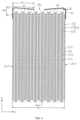
FIG. 1 is a view of a secondary battery according to an embodiment of this application viewed in a second direction; -
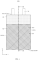
FIG. 2 is a view of an electrode assembly according to an embodiment of this application viewed in a second direction; -
FIG. 3 is a sectional view of the electrode assembly shown inFIG. 2 along III-III; -
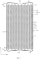
FIG. 4 is a sectional view of the electrode assembly shown inFIG. 1 along IV-IV; -
FIG. 5 is a sectional view of the electrode assembly shown inFIG. 3 along V-V; -
FIG. 6 is a view of an electrode assembly according to another embodiment of this application viewed in a second direction; and -
FIG. 7 is a schematic sectional view of the electrode assembly shown inFIG. 6 along VII-VII. - The following specific embodiments further describe this application with reference to the above drawings.
- The technical solutions in the embodiments of this application are clearly described in detail below. Apparently, the described embodiments are some rather than all of the embodiments of this application. Unless otherwise defined, all technical and scientific terms used herein have the same meanings as those commonly understood by those skilled in the technical field of this application. The terms used in the specification of this application are merely for the purpose of describing specific embodiments, and are not intended to limit this application.
- The embodiments of this application are described in detail below. However, this application should be embodied in many different forms and should not be construed as limited to the exemplary embodiments described herein. Instead, these exemplary embodiments are provided, so that this application will be conveyed to those skilled in the art thoroughly and in detail.
- In addition, for simplicity and clarity, the sizes or thicknesses of various assemblies and layers can be enlarged in the drawings. Throughout the whole specification, the same numerical values refer to the same elements. As used herein, the term "and/or" includes any and all combinations of one or more of associated and listed items. In addition, it should be understood that when an element A is referred to be "connected" with an element B, or an element A and an element B are referred to be connected to each other, the element A may be directly connected to the element B, or an intermediate element C may be present and the element A and the element B may be connected to each other indirectly.
- Further, "may" used in the description of the embodiments of this application refers to "one or more embodiments of this application".
- The technical terms used herein are for the purpose of describing specific embodiments, and are not intended to limit this application. As used therein, the singular form is intended to include the plural form, unless otherwise specified in the context. It should be further understood that the term "include", when used in the specification, refers to the described features, numerical values, steps, operations, elements and/or components, but do not exclude the presence or addition of one or more of other features, numerical values, operations, elements, components and/or combinations thereof.
- It should be understood that although the terms first, second and third may be used herein to describe various elements, components, regions, layers and/or portions, but these elements, components, regions, layers and/or portions should not be limited by these terms. These terms are used to distinguish one element, component, region, layer or portion from another element, component, region, layer or portion. Therefore, a first element, component, region, layer or portion discussed below may be referred to as a second element, component, region, layer or portion without departing from the teaching of the exemplary embodiments.
- Referring to
FIG. 1 andFIG. 2 , one embodiment of this application provides asecondary battery 100, including ahousing 10, anelectrode assembly 20, electrolyte andtabs 30. Theelectrode assembly 20 and the electrolyte are accommodated in thehousing 10. Thetabs 30 are connected to theelectrode assembly 20 and protrude out of one side of thehousing 10 in a first direction X to be connected to an external element. In this embodiment, twotabs 30 are provided, namely a positive electrode tab and a negative electrode tab; and the twotabs 30 are located on the same side of thesecondary battery 100. - The
housing 10 may be a packaging bag packaged by a packaging film (such as aluminum-plastic film or steel-plastic film), that is, thesecondary battery 100 is a pouch battery. Specifically, thehousing 10 includes amain body portion 11 and apackaging portion 12, where themain body portion 11 is provided with an accommodating cavity for accommodating anelectrode assembly 20, and thepackaging portion 12 extends from an edge of themain body portion 11 and is configured to seal themain body portion 11. Thetabs 30 pass through thepackaging portion 12 to extend in the first direction X. In other embodiments, thehousing 10 is a metal housing, for example, a steel housing or an aluminum housing. - Referring to
FIG. 3 , theelectrode assembly 20 includes afirst electrode plate 21, asecond electrode plate 22, and aseparator film 23 arranged between thefirst electrode plate 21 and thesecond electrode plate 22. Thefirst electrode plate 21, theseparator film 23 and thesecond electrode plate 22 are alternately stacked in a second direction Z perpendicular to the first direction X to form a stacked structure. In other embodiments, thefirst electrode plate 21, theseparator film 23 and thesecond electrode plate 22 are stacked and wound to form a winding structure. - The
first electrode plate 21 includes a firstcurrent collector 211 and a firstactive substance layer 212 arranged on at least one surface of the firstcurrent collector 211. Thesecond electrode plate 22 includes a secondcurrent collector 221 and a secondactive substance layer 222 arranged on at least one surface of the secondcurrent collector 221. In this embodiment, thefirst electrode plate 21 is a positive electrode plate, and thesecond electrode plate 22 is a negative electrode plate. The firstcurrent collector 211 and the secondcurrent collector 212 each include at least one of Ni, Ti, Cu, Ag, Au, Pt, Fe, Al and compositions thereof. The firstactive substance layer 212 includes a positive electrode active substance. The positive electrode active substance may include at least one of lithium cobaltate, lithium manganate, lithium nickelate, lithium nickel cobalt manganate, lithium iron phosphate, lithium ferromanganese phosphate, lithium vanadium phosphate, lithium vanadoxy phosphate, a lithium-manganese-enriched material, lithium nickel cobalt aluminate and compositions thereof. the secondactive substance layer 222 includes a negative electrode active substance. The negative active substance may be selected from at least one of a graphite material, an alloy material, lithium metal and alloy thereof. The graphite material may be selected from at least one of artificial graphite and natural graphite. The alloy material may be selected from at least one of silicon, silicon oxide, stannum and titanium sulfide. - Referring to
FIG. 2 andFIG. 4 , theelectrode assembly 20 further includes afirst end face 201 and asecond end face 202 which are opposite to each other in a first direction X, and aside surface 203 surrounding the periphery of thefirst end face 201 and connected between thefirst end face 201 and thesecond end face 202. Thefirst end surface 201 includes an end face of one side of each of afirst electrode plate 21, asecond electrode plate 22 and aseparator film 23 in the first direction X. Thesecond end surface 202 includes an end face of the other side of each of thefirst end surface 21, thesecond end surface 22 and theseparator film 23 in the first direction X. Thetabs 30 protrude from thefirst end face 201 in the first direction X. - Referring to
FIG. 2 to FIG. 4 , thesecondary battery 100 further includes a firstthin film 40. The firstthin film 40 surrounds theelectrode assembly 20 and is configured to fasten theelectrode assembly 20, thereby reducing the risk of contact short circuit of thefirst electrode plate 21 and thesecond electrode plate 22 due to the contraction of theseparator film 23. Specifically, the firstthin film 40 includes a firstmain body portion 41 and a first extendingportion 42 which are connected. The firstthin film 41 surrounds theside surface 203 and is configured to fasten theelectrode assembly 20, thereby reducing the risk of contact short circuit of thefirst electrode plate 21 and thesecond electrode plate 22 due to the contraction of thewhole separator film 23 caused by an insufficient binding force of thewhole electrode assembly 20. In the first direction X, theside surface 203 includes afirst edge 203a of one side where thetabs 30 are located, and asecond edge 203b of a side opposite to one side where thetabs 30 are located. The firstmain body portion 41 extends from thefirst edge 203a to thesecond edge 203b, and is arranged away from thesecond edge 203b. The first extendingportion 42 is bent and extends from an edge of the first extendingportion 41 on one side where thetabs 30 are located, and covers at least part of thefirst end face 201. The first extendingportion 42 covers part of thefirst end face 201 so as to block the electrolyte impact on thefirst end face 201, thereby reducing the risk of contact short circuit of thefirst electrode plate 21 and thesecond electrode plate 22 due to the contraction of theseparator film 23 exposed on thefirst end face 201 caused by the impact of the electrolyte. - In the first direction X, the orthographic projection of the first extending
portion 42 on thefirst end face 201 is located in thefirst end face 201. Specifically, in the first direction X, the orthographic projection area of the first extendingportion 42 on thefirst end face 201 is S1 mm2, and the orthographic projection area of thefirst end face 201 is S2 mm2, 0<S1<S2. Preferably, 20%≤S1/S2<100%, the influence on the volume energy density can be reduced while the risk of contact short circuit of thefirst electrode plate 21 and thesecond electrode plate 22 due to the contraction of theseparator film 23 exposed on thefirst end face 201 caused by the impact of the electrolyte can be reduced. - Referring to
FIG. 4 , in the second direction Z, the thickness of theelectrode assembly 20 is T mm, and the length of the first extendingportion 42 is L mm. In some embodiments of this application, 0<L≤0.5T+2. Preferably, the length of the first extendingportion 42 is greater than 2 mm, that is, 2≤L≤0.5T+2. In some embodiments, the first extendingportion 42 is perpendicular to the firstmain body portion 41, and the distance M from an edge of the first extendingportion 42 close to the firstmain body portion 41 to an edge of the first extending portion away from the firstmain body portion 41 is equal to the length L of the first extendingportion 42 in the second direction Z. In some other embodiments, an included angle between the first extendingportion 42 and the firstmain body portion 41 is an obtuse angle or an acute angle, and the distance M from the edge of the first extendingportion 42 close to the firstmain body portion 41 to the edge of the first extending portion away from the firstmain body portion 41 is greater than the length L of the first extendingportion 42 in the second direction Z. When L is in the above range, the risk of the first extendingportion 42 entering thepackaging portion 12 during packaging of the packaging bag can be reduced, thereby reducing the influence on the sealing property of thehousing 10 and also reducing the influence on the energy density caused by excessive L. - In some embodiments, the elongation at break of the first
thin film 40 is greater than or equal to 1%. In this application, the elongation at break of the firstthin film 40 is measured by the following method: one section of a thin film was taken as a test sample, the test sample was straightened without obvious wrinkles, and at this time, the length of the test sample was measured as an initial length; the sample was put into a mechanical apparatus capable of stretching the sample, the sample was stretched at a constant speed of 0.5 mm/min, and when the sample was broken, the stretched length was ΔL, and the elongation at break ε=(ΔL/L)×100%. When the elongation at break of the firstthin film 40 is in the above range, the firstthin film 40 may be arranged on the surface of theelectrode assembly 20 in a stretching manner, thereby simplifying the processing process. - In some embodiments, the gas permeability of the first
thin film 40 is less than 10000s/100cc. That is, the time of a gas of 100cc penetrating through the firstthin film 40 is 10000 seconds. When the gas permeability of the firstthin film 40 is in the above range, the impact of the electrolyte can be blocked without affecting the infiltration effect of the electrolyte. - Referring to
FIG. 5 , the firstthin film 40 includes asubstrate layer 401. Thesubstrate layer 401 includes a polymer film, a multi-layer polymer film or a nonwoven fabric formed by a polymer; and the polymer includes at least one of polyolefin, polyvinylidene fluoride, polyethylene terephthalate, cellulose, polyimide, polyamide, spandex or polyphenylenediamine. - Referring to
FIG 5 , in some embodiments, the firstthin film 40 further includes a bonding layer 402 arranged on a surface of thesubstrate layer 401, and the bonding layer 402 is bonded with theelectrode assembly 20. The bonding layer 402 may include at least one of polyethylene, polypropylene, phenolic resin, melamine resin, unsaturated polyester resin, epoxy resin, organic silicon resin or polyurethane. - The thickness of the first
thin film 40 is H.FIG. 4 shows the thickness H of the firstmain body portion 41 in the second direction Z. In some embodiments, 0<H≤50µm, for example, H is 1 µm, 2 µm, 5 µm, 8 µm, 10 µm, 15 µm, 20 µm, 30 µm, 40 µm and 50 µm. When the thickness of the firstthin film 40 is in the above range, the influence of the first thin film on the volume energy density can be reduced. Preferably, 4µm<H≤10µm, thereby reducing the influence on the volume energy density can be reduced, and an appropriate strength can be maintained. - Referring to
FIG. 4 , theside surface 203 includes afirst side surface 2031 and asecond side surface 2032 which are opposite to each other in a third direction Y perpendicular to the first direction X and the second direction Z. Thefirst side surface 2031 includes an end face of one side of each of afirst electrode plate 21, asecond electrode plate 22 and aseparator film 23 in a third direction Y. Thesecond side surface 2032 includes an end face of the other side of each of thefirst end surface 21, thesecond end surface 22 and theseparator film 23 in the third direction Y. In other embodiments, in a case that theelectrode assembly 20 has a winding structure, thefirst side surface 2031 includes side surfaces of the first electrode plate 21 (the second electrode plate 22) and/or theseparator film 23 located on an outermost layer of one side of the third direction Y; and thesecond side surface 2032 includes side surfaces of the first electrode plate 21 (the second electrode plate 22) and/or theseparator film 23 located on an outermost layer of the other side of the third direction Y. The firstthin film 40 further includes a start end 40a and a tail end 40b which protrude from thefirst side surface 2031 or thesecond side surface 2032, and the start end 40a and the tail end 40b are overlapped and bonded to form a composite portion 43. In this embodiment, the start end 40a and the tail end 40b protrude from thefirst side surface 2031, that is, the composite portion 43 is arranged on thefirst side surface 2031. In other embodiments, the composite portion 43 is arranged on thesecond side surface 2032. The composite portion 43 is arranged on thefirst side surface 2031 or thesecond side surface 2032, so that when the thin film is stretched, part of the thin film is naturally bent on thefirst end face 201, thereby simplifying the processing process. In other embodiments the start end 40a and the tail end 40b protrude from one of two opposite side surfaces in the second direction Z. The start end 40a and the tail end 40b may be heated, softened and molten for butt fusion to form the composite portion 43. In other embodiments, the start end 40a and the tail end 40b are bonded through adhesion to form the composite portion 43. - Referring to
FIG. 6 andFIG. 7 , in another embodiment, thesecondary battery 100 further includes a secondthin film 50. The secondthin film 50 includes a secondmain body portion 51 and a second extendingportion 52 which are connected. The secondmain body portion 51 surrounds theside surface 203 and is configured to fasten theelectrode assembly 20. The second extendingportion 52 is bent and extends from an edge of the secondmain body portion 51 on one side where thesecond end face 202 is located, and covers at least part of thesecond end face 202, so that the electrolyte impacted on thesecond end face 202 can be blocked, thereby reducing the risk of contact short circuit of thefirst electrode plate 21 and thesecond electrode plate 22 due to the contraction of theseparator film 23 exposed on thefirst end face 202 caused by the impact of the electrolyte. - In the first direction X, the orthographic projection of the second extending
portion 52 on thesecond end face 202 is located in thesecond end face 202. In the first direction X, the orthographic projection area of the second extendingportion 52 on thesecond end face 202 is less than or equal to the orthographic projection area of thesecond end face 202. Preferably, the ratio of the orthographic projection area of the second extendingportion 52 on thesecond end face 202 to the orthographic projection area of thesecond end face 202 is 20%-100%. - The second
thin film 50 may be a polymer film, a multi-layer polymer film or a nonwoven fabric formed by a polymer; and the polymer includes at least one of polyolefin, polyvinylidene fluoride, polyethylene terephthalate, cellulose, polyimide, polyamide, spandex or polyphenylenediamine. The secondthin film 50 may also be bonded with theelectrode assembly 20 through a bonding layer. - In the first direction X, the first
main body portion 41 and the secondmain body portion 51 may be connected or separated. In this embodiment, the firstmain body portion 41 and the secondmain body portion 51 are connected, and the firstthin film 40 and the secondthin film 50 are integrally formed. In a case that theelectrode assembly 20 has a stacked structure, the firstthin film 40 and the secondthin film 50 which are integrally formed can block the impact of the electrolyte on end portions of theelectrode assembly 20 in the first direction X and the third direction Y, thereby reducing the risk of the contraction of any end portion of theseparator film 23 caused by the impact of the electrolyte. - An embodiment of this application provides a manufacturing method for a secondary battery, includes the following steps:
Step S1: an electrode assembly was prepared, where the electrode assembly includes a first end face and a side surface surrounding the periphery of the first end face. - The electrode assembly includes a first electrode plate, a second electrode plate, and a separator film arranged between the first electrode plate and the second electrode plate. The first electrode plate, the separator film and the second electrode plate are alternately stacked into a stacked structure, or are stacked and wound into a winding structure.
- Step S2: the electrode assembly and tabs were connected, where the tabs protrude from the first end face in a first direction.
- Step S3: the electrode assembly was placed on the first thin film. In a third direction perpendicular to the first direction, the first thin film includes a start end and a tail end which are arranged oppositely. In the first direction, the first thin film includes a first main body portion and a first extending portion connected to the first main body portion. The electrode assembly covers the first main body portion, the first extending portion is exposed outside the electrode assembly, and the first extending portion and the tabs are located on the same side of the electrode assembly. In this step, the first thin film is substantially sheet-shaped.
- Step S4: the first thin film was bent, so that the first main body portion surrounded the side surface, and the start end and the tail end were located on the same side of the electrode assembly in the third direction.
- Step S5: the first thin film was stretched in the third direction, so that the first extending portion was bent toward the first end face and covered a part of the first end face. During stretching in the third direction, the first main body portion surrounding the electrode assembly was blocked by the electrode assembly and stretched; the first extending portion exposed outside the electrode assembly was not blocked by the first main body portion and not stretched; and the first extending portion was naturally bent to the first end face along with the stretched first main body portion.
- Step S6: the start end and the tail end were connected, so that the first main body portion fastened the electrode assembly. The start end and the tail end have overlapping portions in the second direction, and the overlapping portions are connected to form a composite portion.
- Step S7: the electrode assembly was placed in the housing, and electrolyte was injected into the housing.
- Another embodiment of this application further provides a manufacturing method for a secondary battery, includes the following steps:
Step S10: an electrode assembly was prepared, where the electrode assembly includes a first end face and a side surface surrounding the periphery of the first end face. - The electrode assembly includes a first electrode plate, a second electrode plate, and a separator film arranged between the first electrode plate and the second electrode plate. The first electrode plate, the separator film and the second electrode plate are alternately stacked into a stacked structure, or are stacked and wound into a winding structure.
- Step S20: the electrode assembly and tabs were connected, where the tabs protrude from the first end face in a first direction.
- Step S30: a first thin film was sleeved on the electrode assembly, where the first thin film includes a first main body portion and a first extending portion connected to the first main body portion, the first main body portion surrounds the side surface, the first extending portion is exposed outside the electrode assembly, and the first extending portion and the tabs are located on the same side of the electrode assembly. In this step, the first thin film is substantially cylindrical.
- Step S40: the first thin film was heated, so that the first extending portion was contracted to cover a part of the first end face.
- Step S50: the electrode assembly was placed in the housing, and electrolyte was injected into the housing.
- In the manufacturing method for the secondary battery, the first thin film is arranged on the surface of the electrode assembly through the stretching or thermal contraction performance of the thin film, so that the processing process is simplified.
- An embodiment of this application further provides an electronic apparatus, including any of the above secondary batteries. The electronic apparatus provided by this application may be, but not limited to, a notebook computer, a pen input computer, a mobile computer, an e-book player, a portable phone, a portable fax machine, a portable copying machine, a portable printer, a stereo headset, a video cassette recorder, a liquid crystal television, a handheld cleaner, a portable CD machine, a mini disk, a transceiver, an electronic notebook, a calculator, a memory card, a portable recorder, a radio, a backup power supply, a motor, an automobile, a motorcycle, a power-assisted bicycle, a luminaire, a toy, a game machine, a clock, an electric tool, a flashlight, a camera, a large battery for household use, a lithium ion capacitor and the like.
- The performance of the secondary battery provided by this application is described below through specific embodiments and comparative examples.
- An
electrode assembly 20 provided with a firstthin film 40 shown inFIG. 4 was input into a housing, and liquid injection, packaging and formation were performed to obtain a finished product battery. The thickness T of theelectrode assembly 20 is 6 mm, the length L of the first extendingportion 42 is 0.1 mm, and the ratio S1/S2 of the orthographic projection area S1 of the first extendingportion 42 on thefirst end surface 201 in the first direction X to the orthographic projection area S2 of the first endfirst end face 201 in the first direction X is 3.33%. - Different from Embodiment 1, the length L of the first extending
portion 42 and the orthographic projection area ratio S1/S2 are different. - The batteries in each embodiment and the comparative example were subjected to a drop test. The test parameters and the test results of each embodiment and the comparative example are shown in Table 1.
- A drop failure rate test method:
a lithium ion battery was pretreated at 25°C, standing was performed in a normal temperature environment for 60 minutes, and the volume of the lithium ion battery was tested before the drop test. The lithium ion battery was put into a clamp, and a drop device was used for free drop from a position with 1.5 m above the ground: head-tail-head right corner-head left corner-tail left corner (the angle: 45±15°), which was repeated for 6 rounds. The voltage of the lithium ion battery was measured and recorded at the end of the drop, and the appearance of the lithium ion battery was checked and photos were taken before and after the test. The drop test passed the determination standards: no smoke, no liquid leakage, and a voltage drop less than 30 mV. A voltage drop test method is to test the voltage of the battery by an internal resistance meter respectively before and after the drop, and the voltage drop is the difference value therebetween.Table 1 Item L (mm) 0.5T+2 (mm) S1/S2 Failure number/total number of drop test Embodiment 1 0.1 5 3.33% 6/10 Embodiment 2 0.5 5 16.67% 5/10 Embodiment 3 1 5 33.33% 1/10 Embodiment 4 2 5 66.67% 0/10 Embodiment 5 4 5 99.6% 0/10 Embodiment 6 5 5 99.6% 0/10 Embodiment 7 0.03 5 1% 6/10 Embodiment 8 0.15 5 5% 6/10 Embodiment 9 0.45 5 15% 5/10 Embodiment 100.6 5 20% 3/10 Embodiment 110.9 5 30% 2/10 Embodiment 121.2 5 40% 2/10 Embodiment 13 1.8 5 60% 0/10 Embodiment 14 2.4 5 80% 0/10 Embodiment 15 3 5 95% 0/10 Comparative Example 1 0 5 0 9/10 Note: X/10 indicates the voltage drop failure number of the tested ten samples is X. - It can be seen from Table 1 that when 0<L≤0.5T+2 and 0<S1<S2 are met, the drop failure probability is small, because the first extending portion of the first thin film blocks the electrolyte impacted on the first end face, thereby reducing the risk of contact of the positive electrode plate caused by the contraction of the separator film due to the impact of the electrolyte. When 20%≤S1/S2<100%, the drop failure rate is less than or equal to 3/10, and the effect is better. Further, when 20%≤S1/S2≤80%, good safety performance can be achieved, and the interference of the separator film on other assemblies can be improved. When 2≤L≤0.5T+2, the voltage drop failure rate is 0/10, and the effect is better.
- What is disclosed above is merely preferred embodiments of this application, and certainly is not intended to limit the scope of the claims of this application. Therefore, equivalent variations made in accordance with the claims of this application still fall within the scope of this application.
| |
100 |
| |
10 |
| |
20 |
| |
30 |
| |
11 |
| |
12 |
| |
21 |
| |
22 |
| |
23 |
| First |
211 |
| First |
212 |
| Second |
221 |
| Second |
222 |
| |
201 |
| |
202 |
| |
203 |
| First |
40 |
| First |
41 |
| First extending |
42 |
| |
203a |
| |
203b |
| |
401 |
| Bonding layer | 402 |
| |
2031 |
| |
2032 |
| Start end | 40a |
| Tail end | 40b |
| Composite portion | 43 |
| Second |
50 |
| Second |
51 |
| Second extending |
52 |
| First direction | X |
| Second direction | Z |
| Third direction | Y |
Claims (18)
- A secondary battery (100), comprising: a housing (10), an electrode assembly (20), an electrolyte, and tabs (30) connected to the electrode assembly (20); the electrode assembly (20) and the electrolyte are accommodated in the housing (10); the electrode assembly (20) comprises a first end face (201) and a side surface (203) surrounding the periphery of the first end face (201); the tabs (30) protrude out from the first end face (201) in a first direction;
characterized in that, the secondary battery further comprising a first thin film (40), the first thin film (40) comprising a first main body portion (41) and a first extending portion (42) connected to each other, the first main body portion (41) surrounding the side surface (203), and the first extending portion (42) covering at least a part of the first end face (201). - The secondary battery (100) according to claim 1, characterized in that, in a second direction perpendicular to the first direction, a thickness of the electrode assembly (20) is T mm, and a length of the first extending portion (42) is L mm, wherein 0<L≤0.5T+2.
- The secondary battery (100) according to claim 2, characterized in that, 2≤L≤0.5T+2.
- The secondary battery (100) according to any one of claims 1-3, characterized in that, the first thin film (40) satisfies at least one of the following conditions:(1) an elongation at break of the first thin film (40) is greater than or equal to 1%; or(2) a gas permeability of the first thin film (40) is less than 10000s/100cc.
- The secondary battery (100) according to any one of claims 1-4, characterized in that, the first thin film (40) comprises a substrate layer (401) comprising a polymer film, a multi-layer polymer film or a nonwoven fabric formed by a polymer; the polymer comprising at least one of polyolefin, polyvinylidene fluoride, polyethylene terephthalate, cellulose, polyimide, polyamide, spandex or polyphenylenediamine.
- The secondary battery (100) according to claim 5, characterized in that, the first thin film (40) further comprises a bonding layer (402) arranged on a surface of the substrate layer (401), the bonding layer (402) being bonded with the electrode assembly (20).
- The secondary battery (100) according to claim 1, characterized in that, a thickness of the first thin film (40) is H, 0<H≤50µm.
- The secondary battery (100) according to claim 7, characterized in that, 4µm≤H≤10µm.
- The secondary battery (100) according to claim 1, characterized in that, the side surface (203) comprises a first side surface (2031) and a second side surface (2032) disposed opposite to each other in a third direction, the third direction is perpendicular to the first direction; and the first thin film (40) comprises a start end (40a) and a tail end (40b) ; the start end (40a) and the tail end (40b) protrude from the first side surface (2031) or the second side surface (2032), the start end (40a) and the tail end (40b) being overlapped and bonded to form a composite portion (43).
- The secondary battery (100) according to claim 1, characterized in that, the electrode assembly (20) further comprises a second end face (202) opposite to the first end face (201) in the first direction; and the secondary battery (100) further comprises a second thin film (50), the second thin film (50) comprising a second main body portion (51) and a second extending portion (52) connected to each other, the second main body portion (51) surrounding the side surface (203), and the second extending portion (52) covering at least a part of the second end face (202).
- The secondary battery (100) according to claim 10, characterized in that, the first main body portion (41) and the second main body portion (51) are connected in the first direction.
- The secondary battery (100) according to claim 11, characterized in that, the electrode assembly (20) is of a stacked structure.
- The secondary battery (100) according to claim 1, characterized in that, in the first direction, an orthographic projection area of the first extending portion (42) on the first end face (201) is S1 mm2, and an area of the first end face (201) is S2 mm2, 0<S1 <S2.
- The secondary battery (100) according to claim 13, characterized in that, 20%≤S1/S2 < 100%.
- The secondary battery (100) according to claim 14, characterized in that, 20%≤S1/S2≤80%.
- A method for manufacturing the secondary battery (100) as claimed in any one of claims 1-15, characterized in that, the method comprises the following steps:preparing the electrode assembly (20);connecting the electrode assembly (20) and the tabs (30), the tabs (30) protruding from the first end face (201) in the first direction;placing the electrode assembly (20) on the first thin film (40), in the first direction; and in a third direction perpendicular to the first direction, the first thin film (40) comprising a start end (40a) and a tail end (40b) arranged opposite to each other;bending the first thin film (40), so that the first main body portion (41) surrounds the side surface (203), and the start end (40a) and the tail end (40b) are located on the same side of the electrode assembly (20) in the third direction;stretching the first thin film (40) in the third direction, so that the first extending portion (42) is bent toward the first end face (201) and covers a part of the first end face (201);connecting the start end (40a) and the tail end (40b), so that the first main body portion (41) fastens the electrode assembly (20); andplacing the electrode assembly (20) in a housing (10), and injecting the electrolyte in the housing (10).
- A method for manufacturing the secondary battery (100) as claimed in claims 1-15, characterized in that, the method comprises the following steps:preparing the electrode assembly (20);connecting the electrode assembly (20) and the tabs (30), the tabs (30) protruding from the first end face (201) in the first direction;sleeving the first thin film (40) on the electrode assembly (20);heating the first thin film (40), so that the first extending portion (42) is contracted to cover a part of the first end face (201); andplacing the electrode assembly (20) in a housing (10), and injecting the electrolyte in the housing (10).
- An electronic apparatus, characterized by comprising the secondary battery (100) according to any one of claims 1 to 15, or a secondary battery (100) prepared by the manufacturing method for a secondary battery (100) according to any one of claims 16 to 17.
Applications Claiming Priority (1)
| Application Number | Priority Date | Filing Date | Title |
|---|---|---|---|
| CN202311272110.9A CN117154176A (en) | 2023-09-28 | 2023-09-28 | Secondary battery, manufacturing method and electronic device thereof |
Publications (1)
| Publication Number | Publication Date |
|---|---|
| EP4531154A1 true EP4531154A1 (en) | 2025-04-02 |
Family
ID=88912194
Family Applications (1)
| Application Number | Title | Priority Date | Filing Date |
|---|---|---|---|
| EP24202577.3A Pending EP4531154A1 (en) | 2023-09-28 | 2024-09-25 | Secondary battery and manufacturing method therefor, and electronic apparatus |
Country Status (2)
| Country | Link |
|---|---|
| EP (1) | EP4531154A1 (en) |
| CN (1) | CN117154176A (en) |
Citations (1)
| Publication number | Priority date | Publication date | Assignee | Title |
|---|---|---|---|---|
| US20220344754A1 (en) * | 2019-10-14 | 2022-10-27 | Lg Energy Solution, Ltd. | Battery Cell, Battery Module Comprising Same Battery Cell, And Battery Pack Comprising Same Battery Module |
-
2023
- 2023-09-28 CN CN202311272110.9A patent/CN117154176A/en active Pending
-
2024
- 2024-09-25 EP EP24202577.3A patent/EP4531154A1/en active Pending
Patent Citations (1)
| Publication number | Priority date | Publication date | Assignee | Title |
|---|---|---|---|---|
| US20220344754A1 (en) * | 2019-10-14 | 2022-10-27 | Lg Energy Solution, Ltd. | Battery Cell, Battery Module Comprising Same Battery Cell, And Battery Pack Comprising Same Battery Module |
Also Published As
| Publication number | Publication date |
|---|---|
| CN117154176A (en) | 2023-12-01 |
Similar Documents
| Publication | Publication Date | Title |
|---|---|---|
| JP5169820B2 (en) | Film exterior electrical device | |
| JP3527858B2 (en) | Battery | |
| KR101567600B1 (en) | Battery pack and method of manufacturing the same | |
| KR100708023B1 (en) | Film-packaged electric device and its manufacturing method | |
| CN100373681C (en) | Non-aqueous electrolyte battery and manufacturing method thereof | |
| CN113540623A (en) | Pouch-type battery case and pouch-type secondary battery | |
| US20160204394A1 (en) | Package for power storage device | |
| US20240421387A1 (en) | Pouch Film and Method for Manufacturing the Same | |
| EP3130461B1 (en) | Composite film and method for manufacturing same | |
| WO2005015659A1 (en) | Cell coated with film and manufacturing method thereof | |
| JP7787826B2 (en) | Non-aqueous electrolyte secondary battery | |
| US20240347861A1 (en) | Secondary battery and electrical device | |
| KR101780583B1 (en) | Composite film for outside material of battery | |
| EP4583267A1 (en) | Secondary battery and electronic apparatus comprising same | |
| WO2013031937A1 (en) | Lithium-ion secondary battery | |
| JPH10289696A (en) | Battery and manufacturing method thereof | |
| EP4525147A2 (en) | Secondary battery and electronic apparatus | |
| JP2000353498A (en) | Manufacturing method of thin battery | |
| CN113924674B (en) | secondary batteries | |
| JP2003157810A (en) | Battery | |
| JP2002367592A (en) | Lithium ion battery | |
| KR102373583B1 (en) | Pouch type secondary cell | |
| CN117154176A (en) | Secondary battery, manufacturing method and electronic device thereof | |
| KR20260045684A (en) | Pouch film lamination, pouch-type battery case and pouch-type secondary battery | |
| CN120858475A (en) | Secondary batteries and electronic devices |
Legal Events
| Date | Code | Title | Description |
|---|---|---|---|
| PUAI | Public reference made under article 153(3) epc to a published international application that has entered the european phase |
Free format text: ORIGINAL CODE: 0009012 |
|
| STAA | Information on the status of an ep patent application or granted ep patent |
Free format text: STATUS: REQUEST FOR EXAMINATION WAS MADE |
|
| 17P | Request for examination filed |
Effective date: 20240925 |
|
| AK | Designated contracting states |
Kind code of ref document: A1 Designated state(s): AL AT BE BG CH CY CZ DE DK EE ES FI FR GB GR HR HU IE IS IT LI LT LU LV MC ME MK MT NL NO PL PT RO RS SE SI SK SM TR |