EP4531006A1 - Multi-module imaging system and image-synchronization method - Google Patents
Multi-module imaging system and image-synchronization method Download PDFInfo
- Publication number
- EP4531006A1 EP4531006A1 EP24165062.1A EP24165062A EP4531006A1 EP 4531006 A1 EP4531006 A1 EP 4531006A1 EP 24165062 A EP24165062 A EP 24165062A EP 4531006 A1 EP4531006 A1 EP 4531006A1
- Authority
- EP
- European Patent Office
- Prior art keywords
- image
- module
- images
- imaging system
- light
- Prior art date
- Legal status (The legal status is an assumption and is not a legal conclusion. Google has not performed a legal analysis and makes no representation as to the accuracy of the status listed.)
- Pending
Links
Images




Classifications
-
- H—ELECTRICITY
- H04—ELECTRIC COMMUNICATION TECHNIQUE
- H04N—PICTORIAL COMMUNICATION, e.g. TELEVISION
- H04N23/00—Cameras or camera modules comprising electronic image sensors; Control thereof
- H04N23/45—Cameras or camera modules comprising electronic image sensors; Control thereof for generating image signals from two or more image sensors being of different type or operating in different modes, e.g. with a CMOS sensor for moving images in combination with a charge-coupled device [CCD] for still images
-
- H—ELECTRICITY
- H04—ELECTRIC COMMUNICATION TECHNIQUE
- H04N—PICTORIAL COMMUNICATION, e.g. TELEVISION
- H04N23/00—Cameras or camera modules comprising electronic image sensors; Control thereof
- H04N23/80—Camera processing pipelines; Components thereof
-
- G—PHYSICS
- G06—COMPUTING OR CALCULATING; COUNTING
- G06V—IMAGE OR VIDEO RECOGNITION OR UNDERSTANDING
- G06V20/00—Scenes; Scene-specific elements
- G06V20/40—Scenes; Scene-specific elements in video content
- G06V20/41—Higher-level, semantic clustering, classification or understanding of video scenes, e.g. detection, labelling or Markovian modelling of sport events or news items
-
- G—PHYSICS
- G06—COMPUTING OR CALCULATING; COUNTING
- G06V—IMAGE OR VIDEO RECOGNITION OR UNDERSTANDING
- G06V20/00—Scenes; Scene-specific elements
- G06V20/60—Type of objects
- G06V20/62—Text, e.g. of license plates, overlay texts or captions on TV images
- G06V20/625—License plates
-
- G—PHYSICS
- G06—COMPUTING OR CALCULATING; COUNTING
- G06V—IMAGE OR VIDEO RECOGNITION OR UNDERSTANDING
- G06V30/00—Character recognition; Recognising digital ink; Document-oriented image-based pattern recognition
- G06V30/10—Character recognition
- G06V30/20—Combination of acquisition, preprocessing or recognition functions
-
- H—ELECTRICITY
- H04—ELECTRIC COMMUNICATION TECHNIQUE
- H04N—PICTORIAL COMMUNICATION, e.g. TELEVISION
- H04N19/00—Methods or arrangements for coding, decoding, compressing or decompressing digital video signals
- H04N19/44—Decoders specially adapted therefor, e.g. video decoders which are asymmetric with respect to the encoder
-
- H—ELECTRICITY
- H04—ELECTRIC COMMUNICATION TECHNIQUE
- H04N—PICTORIAL COMMUNICATION, e.g. TELEVISION
- H04N23/00—Cameras or camera modules comprising electronic image sensors; Control thereof
- H04N23/10—Cameras or camera modules comprising electronic image sensors; Control thereof for generating image signals from different wavelengths
- H04N23/11—Cameras or camera modules comprising electronic image sensors; Control thereof for generating image signals from different wavelengths for generating image signals from visible and infrared light wavelengths
-
- H—ELECTRICITY
- H04—ELECTRIC COMMUNICATION TECHNIQUE
- H04N—PICTORIAL COMMUNICATION, e.g. TELEVISION
- H04N5/00—Details of television systems
- H04N5/222—Studio circuitry; Studio devices; Studio equipment
- H04N5/262—Studio circuits, e.g. for mixing, switching-over, change of character of image, other special effects ; Cameras specially adapted for the electronic generation of special effects
- H04N5/265—Mixing
-
- H—ELECTRICITY
- H04—ELECTRIC COMMUNICATION TECHNIQUE
- H04N—PICTORIAL COMMUNICATION, e.g. TELEVISION
- H04N7/00—Television systems
- H04N7/18—Closed-circuit television [CCTV] systems, i.e. systems in which the video signal is not broadcast
- H04N7/183—Closed-circuit television [CCTV] systems, i.e. systems in which the video signal is not broadcast for receiving images from a single remote source
-
- G—PHYSICS
- G06—COMPUTING OR CALCULATING; COUNTING
- G06V—IMAGE OR VIDEO RECOGNITION OR UNDERSTANDING
- G06V30/00—Character recognition; Recognising digital ink; Document-oriented image-based pattern recognition
- G06V30/10—Character recognition
- G06V30/14—Image acquisition
- G06V30/141—Image acquisition using multiple overlapping images; Image stitching
Definitions
- the present invention relates to a synchronous image output technology, and more particularly to a multi-module imaging system and an image-synchronization method that stitch multiple images outputted by an image signal processor so as to achieve image synchronization.
- a conventional automatic license plate recognition (ALPR) system of a vehicle can be equipped with a plurality of light-sensing modules, such as infrared sensors and visible-light sensors that can be used to capture color images, so as to simultaneously capture images of scenes and license plates of the other vehicles in front of the vehicle.
- the visible-light sensor is used to capture the color images covering the other vehicles and the surroundings.
- the license plate recognition would be erroneous since the color images are easily affected by changes of ambient light. Therefore, the infrared sensor is also used to capture an infrared image of the license plate. The infrared image will not be affected by the ambient light. Even if under a low light source and bad weather conditions, the infrared sensor is still able to capture a clear license plate image that can be correctly recognized, thereby improving the license-plate recognition performance.
- a camera installed in a police vehicle is equipped with the automatic license plate recognition system that can automatically detect and recognize the license plate of the vehicle in front of the police vehicle. If the vehicle ahead uses the license plate that can reflect light, when headlights of the police vehicle illuminate on the front license plate, this front license plate will cause glare that affects the accuracy of license-plate recognition. Therefore, the infrared sensor is used in the ALPR system for filtering out the glare, so as to capture a clear image of the license plate.
- the images respectively generated by the infrared sensor and the visible-light sensor are individually compressed and outputted.
- the system is required to ensure that the images were taken at the same time by synchronously outputting the images.
- an in-vehicle imaging system that adopts both the infrared sensor and the visible-light sensor is used.
- the in-vehicle imaging system is required to process the images respectively captured by the infrared sensor and the visible-light sensor.
- Circuits and software of the in-vehicle imaging system are used to resolve the issue of synchronization of the images. For example, an output timecode or a timestamp of each of the images can be referred to for conducting synchronization of the images.
- the process of synchronization of the images needs to be performed on a device with a powerful computing capability, and consumes substantial computing and time resources.
- an image-synchronization method that can be performed by a device with less computing capability and a multi-module imaging system performing the same.
- the multi-module imaging system includes a camera assembly including multiple light-sensing modules, an image signal processor and a data processor.
- the multi-module imaging system performs the image-synchronization method.
- the camera assembly having the multiple light-sensing modules is used to generate multiple sets of motion images.
- the image signal processor extracts a set of continuous frame images from one of the sets of motion images generated by each of the light-sensing modules of the camera assembly. Multiple sets of continuous frame images are formed from the multiple sets of motion images generated by different light-sensing modules.
- the data processor generates a composite frame by combining multiple frame images that are captured at the same time and extracted from the multiple sets of continuous frame images.
- the multiple sets of motion image can be encoded into multiple continuously-outputted multiple composite frames.
- Each of the composite frames includes multiple frame images generated by the camera assembly at the same time.
- the multi-module imaging system can synchronously output the frame images generated by the different light-sensing modules.
- the image signal processor After the multiple sets of motion images are obtained, the image signal processor performs an image-processing procedure on each of the multiple sets of motion images.
- the image-processing procedure includes one or any combination of noise reduction, color correction, white balance adjustment, contrast adjustment, saturation adjustment and sharpness enhancement that are used to optimize the images.
- the continuously-outputted multiple composite frames are transmitted to an external system according to a time sequence so as to generate the synchronized multiple sets of continuous frame images by performing a decoding procedure.
- the multi-module imaging system is disposed in a drive recorder.
- the drive recorder includes a communication circuit that is used to transmit the multiple composite frames to the external system in a wireless or wired connection manner.
- the camera assembly includes an infrared module and at least one visible light module
- the composite frame includes an infrared image generated by the infrared module and at least one visible light image generated by the at least one visible light module.
- the multi-module imaging system can be applied to an automatic license plate recognition that acquires a license plate image by the infrared module and an environmental image having the vehicle by the visible light module.
- the automatic license plate recognition system is used to recognize the characters combining English alphabets and numbers in the license plate image. The recognized characters can also be combined into the composite frame.
- the camera assembly adopts a global shutter that allows all of the light-sensing pixels of the infrared module and at least one of the visible light modules to be synchronously exposed at the same time so as to generate the frame images.
- the multiple frame images that are obtained at the same time form the composite frame by a stitching procedure by a data processor.
- a vertical encoding procedure is used to stitch the multiple frame images that are obtained at the same time.
- the present invention relates to a multi-module imaging system and an image-synchronization method.
- the multi-module imaging system includes multiple camera assemblies.
- the multiple camera assemblies are installed in an electronic device.
- the multiple camera assemblies include multiple lenses, multiple light-sensing elements and a processing circuit.
- Fig. 1 is a schematic diagram illustrating a circumstance that the multi-module imaging system is used to capture images.
- a drive recorder 10 installed in a vehicle is used to capture images in front of the vehicle.
- the drive recorder 10 includes the multi-module imaging system.
- the present example shows that the multi-module imaging system includes a first camera module 101 and a second camera module 102. These two camera modules can respectively include their own camera lenses for capturing two overlapped images at two different viewing angles in front of the vehicle.
- a front vehicle 110 is included in the overlapped images.
- One of the objectives of the multi-module imaging system is to capture and recognize an image of a license plate 111 of the vehicle 110.
- the drive recorder 10 can be use the image-sensing elements in various wave bands, e.g., two or more visible light-sensing elements, or an assembly of an infrared light-sensing element and a visible light-sensing element, to acquire images.
- the infrared light-sensing element is used to obtain a license plate image in an infrared wave band
- the visible light-sensing element is used to obtain a color image.
- the camera assembly can also include a light-sensing element with a global shutter (GS).
- All of the sensitive pixels of the light-sensing elements including the infrared module and at least one visible light module are sensitive to the light at the same time so as to generate frame images that are synchronously exposed by the light-sensing elements.
- the further advantages of using the global shutter are such as preventing image distortion and reducing heating of the light-sensing elements through the light-sensing element and the infrared light source (e.g., an IR LED flash) of the global shutter at a high-speed synchronized exposure time.
- the drive recorder 10 installed in the police vehicle can capture the front images in a full time when the police vehicle is driving and can recognize multiple license plates (including the license plate 111) of multiple vehicles (including the vehicle 110) in real time by capturing the images during law enforcement.
- the drive recorder 10 of the police vehicle can determine traffic and road conditions based on the front images.
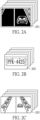
- Fig. 2A to Fig. 2C are schematic diagrams illustrating the images generated by the multi-module imaging system according to certain embodiments of the present invention.
- Fig. 2A is a schematic diagram of a front image of a vehicle captured by an infrared module.
- a series of infrared images 201 shown in the diagram are the images with a narrow viewing angle and each of which includes a bright license plate image with a black-filtered background.
- Fig. 2B and Fig. 2C are schematic diagrams depicting visible light images generated by the multi-module imaging system according to one embodiment of the present invention.
- the multi-module imaging system recognizes a license plate image in an image by an image-processing method or an intelligent model.
- Fig. 2B shows that the multi-module imaging system continuously generates license plate images 202 by the camera modules and can be recognized by an image-processing process or an intelligent model.
- Fig. 2C schematically shows a series of visible light images 203 that are generated by the visible light module.
- One of the visible light images 203 covers the image of a whole scene in front the vehicle.
- the multi-module imaging system of the present invention directly combines the images outputted by an image signal processor (ISP) of the multi-module imaging system.
- ISP image signal processor
- Fig. 3 is a circuit diagram of the multi-module imaging system according to one embodiment of the present invention.
- the multi-module imaging system shown in Fig. 3 can be installed in a drive recorder.
- Main circuits of the system include a camera assembly 300 having multiple light-sensing modules that are electrically interconnected, an image signal processor 303, a data processor 304 and a memory 305.
- the multi-module imaging system also includes a communication circuit 306 that can transmit images to an external system in a wireless or wired communication manner.
- the camera assembly 300 of the multi-module imaging system includes multiple light-sensing modules such as a first light-sensing module 301 and a second light-sensing module 302 of Fig. 3 .
- the light-sensing element is, but not limited to, used to sense the light at a specific wave band.
- the first light-sensing module 301 can be an infrared module that is used to capture an infrared image
- the second light-sensing module 302 can be a visible light module that is used to capture a visible light image.
- the quantity of the light-sensing modules is not limited to the diagram shown in Fig. 3 .
- the image signal processor 303 of the multi-module imaging system is used to process the signals sensed by the first light-sensing module 301 and the second light-sensing module 302 and convert the signals into an image data. Taking the infrared module and the visible light module as an example, the image signals processed by the image signal processor 303 render an infrared image and a visible light image.
- the multi-module imaging system generates multiple sets of motion images by multiple light-sensing modules of the camera assembly 300.
- the image signal processor 303 can then perform an image-processing procedure on each of the sets of motion images.
- the image-processing procedure includes one or any combination of noise reduction, color correction, white balance adjustment, contrast adjustment, saturation adjustment, and sharpness enhancement that are used to optimize the images.
- the motion images generated by the image signal processor 303 include continuous frame images.
- the multiple light-sensing modules respectively generate multiple sets of continuous frame images that can firstly buffered in the memory 305.
- An image synchronization procedure is performed after the motion images are obtained by the data processor 304.
- the frame images generated at the same time are received by the image signal processor 303, and the frame images can be combined (e.g., being stitched) so as to generate a composite frame.
- the composite frame can be transmitted to an external system via a communication circuit 306.
- the camera assembly of the multi-module imaging system includes an infrared module and at least one visible light module that respectively generate continuous infrared frames and continuous visible light frames.
- the composite frame can therefore be a combination of an infrared image and at least one visible light image.
- the multi-module imaging system operated in the drive recorder can continuously generate the composite frames including the multiple images that are synchronized and stitched.
- a first image of the composite image can be an infrared image that is used to obtain a license plate image not affected by an ambient light.
- a second image can be a visible light image of an entire scene in front of the vehicle.
- the continuously-generated composite frames can be transmitted to a computer device of the police vehicle via a communication circuit of the drive recorder.
- the composite frames can be provided for further law enforcement.
- the composite frames can be transmitted to a control center for future reference.
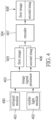
- Fig. 4 is a schematic diagram illustrating a composite frame that is obtained by performing a vertical encoding procedure according to one embodiment of the present invention.
- a camera assembly 400 of the multi-module imaging system includes an infrared module 401 and a visible light module 402.
- the multi-module imaging system can be applied to an automatic license plate recognition (ALPR) system for capturing the license plate images not affected by an ambient light by the infrared module 401, and therefore the ALPR system can recognize the license plate in a scene under a low light source, a bad weather or a poor visibility.
- the ALPR system can continuously recognize the characters combining English alphabets and numbers of the license plate image.
- the visible light module 402 is used to acquire an environmental image having the vehicle.
- the environmental image can be a visible light image that is a color image formed by red, blue and green lights.
- the visible light image is used to identify a color of the vehicle, a brand of the vehicle, a manufacturer of the vehicle, a model of the vehicle and other details.
- the multi-module imaging system generates signals of multiple sets of motion images that are captured by multiple light-sensing modules such as the infrared module 401 and the visible light module 402.
- the image signals that are generated at the same time are processed by an image signal processor 403 for forming a first image 405 and a second image 406.
- the data processor 403 of the multi-module imaging system of Fig. 3 performs an encoding procedure.
- an encoder 407 is used to perform encoding on the first image 405 and the second image 406 so as to form a composite frame 408 in a stitching manner.
- the composite frame 408 can be a stitched frame by stitching multiple frame images by performing a vertical encoding procedure.
- the composite frame 408 includes multiple frame images that are generated by the camera assembly 400 at the same time.
- the multi-module imaging system can synchronously output multiple frame images generated by different light-sensing modules without synchronizing the images according to the time information of the images in any post-production process.
- Fig. 5 is a schematic diagram illustrating the external system that is used to decode and separate the frame images according to one embodiment of the present invention.
- the external system 408 When the composite frame 408 including a first image 405 and a second image 406 is transmitted to the external system, the external system 408 is able to decode the composite frame 408 by a decoder 501 according to an encoding format and to separate the composite frame 408 for restoring a first image 405' and a second image 406'.
- the separated first image 405' and the second image 406' are stored to a storage device 505.
- Fig. 6 is a flowchart illustrating the image-synchronization method that forms the composite frame by performing a vertical encoding procedure shown in Fig. 4 according to one embodiment of the present invention.
- the multiple light-sensing modules of the camera assembly generate multiple sets of motion image (step S601).
- the different light-sensing modules such as the infrared module 401 and the visible light module 402 can continuously output the infrared images and the visible light images.
- the image signal processor 403 extracts a set of continuous frame images from one of the multiple sets of motion images, and multiple sets of continuous frame images can be obtained from the multiple sets of motion image (step S603).
- the multiple frame images e.g., the first image 405 and the second image 406) that are captured at the same time can be obtained from the multiple sets of continuous frame images (step S605).
- the frame images that are captured at the same time can be encoded by the encoder 407 into a composite frame 408 (step S607). Therefore, the multiple sets of motion image can be encoded into continuously-outputted multiple composite frames 408, and each of the composite frames 408 includes multiple frame images that are captured by the camera assembly at the same time. The composite frames are then continuously outputted.
- the multiple composite frames are continuously outputted according to a time sequence.
- the continuously-outputted composite frames are transmitted to the external system, and the synchronized multiple sets of continuous frame images can be obtained by performing a decoding procedure in the external system.
- the infrared image in the composite frame can be a license plate image
- the ALPR system operated in the external system can recognize the license plate and combine multiple characters of the license plate into the composite frame.
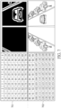
- Fig. 7 is a schematic diagram illustrating a vertically-stitched composite frame formed by stitching multiple frame images that are obtained at the same time by performing a vertical encoding procedure according to one embodiment of the present invention.
- a first image 701 shown in the diagram is composed of pixels numbered 0 to 79.
- a second image 702 vertically adjacent to the first image 701 is composed of pixels numbered 80 to 159.
- the vertically-encoded first image 701 shown in Fig. 7 corresponds to an infrared image 201 that is captured by the infrared module shown in Fig. 2A .
- the second image 702 corresponds to the visible light image 203 that is captured by the visible light module shown in Fig. 2C .
- the composite frame is not limited to the image that is vertically encoded in the diagram, and the composite frame can be a horizontally-encoded image.
- the advantage of the vertically-encoded composite frame is that, without any edge-scanning algorithm, the encoder of the external system can immediately acknowledge a division between the adjacent images of the composite frame by only recognizing the size and the resolution (i.e., the quantity of pixels in a length and a width) of the images.
- the external system can acquire image information when receiving the composite frame. For example, since both images are 10 by 8 pixels in length and in width, the external system can recognize that the pixels of the first image are numbered 0 to 79 and the pixels of the second image are numbered 80 to 159 and therefore recognize the division between the two images.
- the image-synchronization method can be adapted to the composite frame that is obtained by vertically encoding the image with different sizes or resolutions.
- the decoder can decode the composite frame according to a known size of the image.
- the system includes a plurality of light-sensing modules that can capture multiple images including an infrared images and visible light images.
- the infrared image is beneficial to recognize license plate and the visible light image covers the vehicle and the environment.
- the multi-module imaging system can recognize the license plate and obtain an entire environmental image.
- the image-synchronization method utilizes a stitching method to output the synchronized images that are generated at the same time.
Landscapes
- Engineering & Computer Science (AREA)
- Multimedia (AREA)
- Signal Processing (AREA)
- Physics & Mathematics (AREA)
- General Physics & Mathematics (AREA)
- Theoretical Computer Science (AREA)
- Computational Linguistics (AREA)
- Software Systems (AREA)
- Computer Vision & Pattern Recognition (AREA)
- Human Computer Interaction (AREA)
- Studio Devices (AREA)
Abstract
Description
- The present invention relates to a synchronous image output technology, and more particularly to a multi-module imaging system and an image-synchronization method that stitch multiple images outputted by an image signal processor so as to achieve image synchronization.
- A conventional automatic license plate recognition (ALPR) system of a vehicle can be equipped with a plurality of light-sensing modules, such as infrared sensors and visible-light sensors that can be used to capture color images, so as to simultaneously capture images of scenes and license plates of the other vehicles in front of the vehicle. The visible-light sensor is used to capture the color images covering the other vehicles and the surroundings. However, the license plate recognition would be erroneous since the color images are easily affected by changes of ambient light. Therefore, the infrared sensor is also used to capture an infrared image of the license plate. The infrared image will not be affected by the ambient light. Even if under a low light source and bad weather conditions, the infrared sensor is still able to capture a clear license plate image that can be correctly recognized, thereby improving the license-plate recognition performance.
- For example, a camera installed in a police vehicle is equipped with the automatic license plate recognition system that can automatically detect and recognize the license plate of the vehicle in front of the police vehicle. If the vehicle ahead uses the license plate that can reflect light, when headlights of the police vehicle illuminate on the front license plate, this front license plate will cause glare that affects the accuracy of license-plate recognition. Therefore, the infrared sensor is used in the ALPR system for filtering out the glare, so as to capture a clear image of the license plate.
- The images respectively generated by the infrared sensor and the visible-light sensor are individually compressed and outputted. When the images are separately decompressed, the system is required to ensure that the images were taken at the same time by synchronously outputting the images. In the conventional ALPR system, an in-vehicle imaging system that adopts both the infrared sensor and the visible-light sensor is used. The in-vehicle imaging system is required to process the images respectively captured by the infrared sensor and the visible-light sensor. Circuits and software of the in-vehicle imaging system are used to resolve the issue of synchronization of the images. For example, an output timecode or a timestamp of each of the images can be referred to for conducting synchronization of the images. However, the process of synchronization of the images needs to be performed on a device with a powerful computing capability, and consumes substantial computing and time resources.
- In response to the above-referenced technical inadequacies of the conventional technologies that require a greater computing capability to perform image synchronization when processing images generated by multiple light-sensing modules that is not suitable for an edge device (e.g., a drive recorder) with a poor computing capability, provided in the present invention is an image-synchronization method that can be performed by a device with less computing capability and a multi-module imaging system performing the same.
- The multi-module imaging system includes a camera assembly including multiple light-sensing modules, an image signal processor and a data processor. The multi-module imaging system performs the image-synchronization method.
- In the image-synchronization method, the camera assembly having the multiple light-sensing modules is used to generate multiple sets of motion images. The image signal processor extracts a set of continuous frame images from one of the sets of motion images generated by each of the light-sensing modules of the camera assembly. Multiple sets of continuous frame images are formed from the multiple sets of motion images generated by different light-sensing modules.
- Next, the data processor generates a composite frame by combining multiple frame images that are captured at the same time and extracted from the multiple sets of continuous frame images. The multiple sets of motion image can be encoded into multiple continuously-outputted multiple composite frames. Each of the composite frames includes multiple frame images generated by the camera assembly at the same time. The multi-module imaging system can synchronously output the frame images generated by the different light-sensing modules.
- After the multiple sets of motion images are obtained, the image signal processor performs an image-processing procedure on each of the multiple sets of motion images. The image-processing procedure includes one or any combination of noise reduction, color correction, white balance adjustment, contrast adjustment, saturation adjustment and sharpness enhancement that are used to optimize the images.
- Further, when the composite frames are continuously outputted, the continuously-outputted multiple composite frames are transmitted to an external system according to a time sequence so as to generate the synchronized multiple sets of continuous frame images by performing a decoding procedure.
- In an aspect, the multi-module imaging system is disposed in a drive recorder. The drive recorder includes a communication circuit that is used to transmit the multiple composite frames to the external system in a wireless or wired connection manner.
- The camera assembly includes an infrared module and at least one visible light module, and the composite frame includes an infrared image generated by the infrared module and at least one visible light image generated by the at least one visible light module.
- Further, the multi-module imaging system can be applied to an automatic license plate recognition that acquires a license plate image by the infrared module and an environmental image having the vehicle by the visible light module. The automatic license plate recognition system is used to recognize the characters combining English alphabets and numbers in the license plate image. The recognized characters can also be combined into the composite frame.
- Still further, the camera assembly adopts a global shutter that allows all of the light-sensing pixels of the infrared module and at least one of the visible light modules to be synchronously exposed at the same time so as to generate the frame images.
- Further, the multiple frame images that are obtained at the same time form the composite frame by a stitching procedure by a data processor. In particular, a vertical encoding procedure is used to stitch the multiple frame images that are obtained at the same time.
- These and other aspects of the present invention will become apparent from the following description of the embodiment taken in conjunction with the following drawings and their captions, although variations and modifications therein may be affected without departing from the spirit and scope of the novel concepts of the invention.
- The described embodiments may be better understood by reference to the following descriptions and the accompanying drawings, in which:
-
Fig. 1 is a schematic diagram illustrating a circumstance that a multi-module imaging system is used to capture images in one embodiment of the present invention; -
Fig. 2A is a schematic diagram illustrating a bright license plate image with a black-filtered background captured by an infrared module; -
Fig. 2B is a schematic diagram illustrating images that are continuously generated by a first camera module; -
Fig. 2C is a schematic diagram illustrating images that are continuously generated by a second camera module; -
Fig. 3 is a schematic diagram of circuit elements of the multi-module imaging system according to one embodiment of the present invention; -
Fig. 4 is a schematic diagram illustrating a composite frame that is obtained by performing a vertical encoding procedure according to one embodiment of the present invention; -
Fig. 5 is a schematic diagram illustrating an external system that is used to decode and separate the frame images according to one embodiment of the present invention; -
Fig. 6 is a flowchart illustrating an image-synchronization method operated in the multi-module imaging system according to one embodiment of the present invention; and -
Fig. 7 is a schematic diagram illustrating a composite frame and a corresponding image in one embodiment of the present invention. - The present invention is more particularly described in the following examples that are intended as illustrative only since numerous modifications and variations therein will be apparent to those skilled in the art. Like numbers in the drawings indicate like components throughout the views. As used in the description herein and throughout the claims that follow, unless the context clearly dictates otherwise, the meaning of "a," "an" and "the" includes plural reference, and the meaning of "in" includes "in" and "on." Titles or subtitles can be used herein for the convenience of a reader, which shall have no influence on the scope of the present invention.
- The terms used herein generally have their ordinary meanings in the art. In the case of conflict, the present document, including any definitions given herein, will prevail. The same thing can be expressed in more than one way. Alternative language and synonyms can be used for any term(s) discussed herein, and no special significance is to be placed upon whether a term is elaborated or discussed herein. A recital of one or more synonyms does not exclude the use of other synonyms. The use of examples anywhere in this specification including examples of any terms is illustrative only, and in no way limits the scope and meaning of the present invention or of any exemplified term. Likewise, the present invention is not limited to various embodiments given herein. Numbering terms such as "first," "second" or "third" can be used to describe various components, signals or the like, which are for distinguishing one component/signal from another one only, and are not intended to, nor should be construed to impose any substantive limitations on the components, signals or the like.
- The present invention relates to a multi-module imaging system and an image-synchronization method. The multi-module imaging system includes multiple camera assemblies. For example, the multiple camera assemblies are installed in an electronic device. The multiple camera assemblies include multiple lenses, multiple light-sensing elements and a processing circuit. Reference is made to
Fig. 1 , which is a schematic diagram illustrating a circumstance that the multi-module imaging system is used to capture images. - A
drive recorder 10 installed in a vehicle is used to capture images in front of the vehicle. In particular, thedrive recorder 10 includes the multi-module imaging system. The present example shows that the multi-module imaging system includes afirst camera module 101 and asecond camera module 102. These two camera modules can respectively include their own camera lenses for capturing two overlapped images at two different viewing angles in front of the vehicle. Afront vehicle 110 is included in the overlapped images. One of the objectives of the multi-module imaging system is to capture and recognize an image of alicense plate 111 of thevehicle 110. - In one further embodiment of the present invention, for license plate recognition, a clear license plate image is required. The
drive recorder 10 can be use the image-sensing elements in various wave bands, e.g., two or more visible light-sensing elements, or an assembly of an infrared light-sensing element and a visible light-sensing element, to acquire images. For example, the infrared light-sensing element is used to obtain a license plate image in an infrared wave band, and the visible light-sensing element is used to obtain a color image. The camera assembly can also include a light-sensing element with a global shutter (GS). All of the sensitive pixels of the light-sensing elements including the infrared module and at least one visible light module are sensitive to the light at the same time so as to generate frame images that are synchronously exposed by the light-sensing elements. The further advantages of using the global shutter are such as preventing image distortion and reducing heating of the light-sensing elements through the light-sensing element and the infrared light source (e.g., an IR LED flash) of the global shutter at a high-speed synchronized exposure time. - Taking a police vehicle as an example, the
drive recorder 10 installed in the police vehicle can capture the front images in a full time when the police vehicle is driving and can recognize multiple license plates (including the license plate 111) of multiple vehicles (including the vehicle 110) in real time by capturing the images during law enforcement. In addition to recognizing the license plate, thedrive recorder 10 of the police vehicle can determine traffic and road conditions based on the front images. -
Fig. 2A to Fig. 2C are schematic diagrams illustrating the images generated by the multi-module imaging system according to certain embodiments of the present invention. -
Fig. 2A is a schematic diagram of a front image of a vehicle captured by an infrared module. A series ofinfrared images 201 shown in the diagram are the images with a narrow viewing angle and each of which includes a bright license plate image with a black-filtered background. -
Fig. 2B and Fig. 2C are schematic diagrams depicting visible light images generated by the multi-module imaging system according to one embodiment of the present invention. The multi-module imaging system recognizes a license plate image in an image by an image-processing method or an intelligent model. -
Fig. 2B shows that the multi-module imaging system continuously generateslicense plate images 202 by the camera modules and can be recognized by an image-processing process or an intelligent model.Fig. 2C schematically shows a series of visiblelight images 203 that are generated by the visible light module. One of the visiblelight images 203 covers the image of a whole scene in front the vehicle. - Rather than the conventional technologies that use a post-production process to synchronize the continuous images captured by the camera modules, the multi-module imaging system of the present invention directly combines the images outputted by an image signal processor (ISP) of the multi-module imaging system. In other words, rather than respectively outputting the continuous images generated by the different camera modules, the multi-module imaging system continuously outputs a series of composite frames.
- Reference is made to
Fig. 3 , which is a circuit diagram of the multi-module imaging system according to one embodiment of the present invention. The multi-module imaging system shown inFig. 3 can be installed in a drive recorder. Main circuits of the system include acamera assembly 300 having multiple light-sensing modules that are electrically interconnected, animage signal processor 303, adata processor 304 and amemory 305. The multi-module imaging system also includes acommunication circuit 306 that can transmit images to an external system in a wireless or wired communication manner. - The
camera assembly 300 of the multi-module imaging system includes multiple light-sensing modules such as a first light-sensing module 301 and a second light-sensing module 302 ofFig. 3 . The light-sensing element is, but not limited to, used to sense the light at a specific wave band. In one of the embodiments of the present invention, the first light-sensing module 301 can be an infrared module that is used to capture an infrared image, and the second light-sensing module 302 can be a visible light module that is used to capture a visible light image. The quantity of the light-sensing modules is not limited to the diagram shown inFig. 3 . - The
image signal processor 303 of the multi-module imaging system is used to process the signals sensed by the first light-sensing module 301 and the second light-sensing module 302 and convert the signals into an image data. Taking the infrared module and the visible light module as an example, the image signals processed by theimage signal processor 303 render an infrared image and a visible light image. - Further, the multi-module imaging system generates multiple sets of motion images by multiple light-sensing modules of the
camera assembly 300. Theimage signal processor 303 can then perform an image-processing procedure on each of the sets of motion images. The image-processing procedure includes one or any combination of noise reduction, color correction, white balance adjustment, contrast adjustment, saturation adjustment, and sharpness enhancement that are used to optimize the images. - The motion images generated by the
image signal processor 303 include continuous frame images. The multiple light-sensing modules respectively generate multiple sets of continuous frame images that can firstly buffered in thememory 305. An image synchronization procedure is performed after the motion images are obtained by thedata processor 304. The frame images generated at the same time are received by theimage signal processor 303, and the frame images can be combined (e.g., being stitched) so as to generate a composite frame. The composite frame can be transmitted to an external system via acommunication circuit 306. - In one further embodiment of the present invention, the camera assembly of the multi-module imaging system includes an infrared module and at least one visible light module that respectively generate continuous infrared frames and continuous visible light frames. The composite frame can therefore be a combination of an infrared image and at least one visible light image.
- Taking a drive recorder installed in a police vehicle as an example, the multi-module imaging system operated in the drive recorder can continuously generate the composite frames including the multiple images that are synchronized and stitched. A first image of the composite image can be an infrared image that is used to obtain a license plate image not affected by an ambient light. A second image can be a visible light image of an entire scene in front of the vehicle. The continuously-generated composite frames can be transmitted to a computer device of the police vehicle via a communication circuit of the drive recorder. The composite frames can be provided for further law enforcement. On the other hand, the composite frames can be transmitted to a control center for future reference.
- Reference is made to
Fig. 4 , which is a schematic diagram illustrating a composite frame that is obtained by performing a vertical encoding procedure according to one embodiment of the present invention. - A
camera assembly 400 of the multi-module imaging system includes aninfrared module 401 and avisible light module 402. The multi-module imaging system can be applied to an automatic license plate recognition (ALPR) system for capturing the license plate images not affected by an ambient light by theinfrared module 401, and therefore the ALPR system can recognize the license plate in a scene under a low light source, a bad weather or a poor visibility. The ALPR system can continuously recognize the characters combining English alphabets and numbers of the license plate image. In the meantime, thevisible light module 402 is used to acquire an environmental image having the vehicle. The environmental image can be a visible light image that is a color image formed by red, blue and green lights. The visible light image is used to identify a color of the vehicle, a brand of the vehicle, a manufacturer of the vehicle, a model of the vehicle and other details. - The multi-module imaging system generates signals of multiple sets of motion images that are captured by multiple light-sensing modules such as the
infrared module 401 and thevisible light module 402. The image signals that are generated at the same time are processed by animage signal processor 403 for forming afirst image 405 and asecond image 406. Thedata processor 403 of the multi-module imaging system ofFig. 3 performs an encoding procedure. As shown in the diagram, anencoder 407 is used to perform encoding on thefirst image 405 and thesecond image 406 so as to form acomposite frame 408 in a stitching manner. For example, thecomposite frame 408 can be a stitched frame by stitching multiple frame images by performing a vertical encoding procedure. - The
composite frame 408 includes multiple frame images that are generated by thecamera assembly 400 at the same time. The multi-module imaging system can synchronously output multiple frame images generated by different light-sensing modules without synchronizing the images according to the time information of the images in any post-production process. - Next, the synchronized
composite frame 408 can be transmitted to another system, and reference is made toFig. 5 , which is a schematic diagram illustrating the external system that is used to decode and separate the frame images according to one embodiment of the present invention. - When the
composite frame 408 including afirst image 405 and asecond image 406 is transmitted to the external system, theexternal system 408 is able to decode thecomposite frame 408 by adecoder 501 according to an encoding format and to separate thecomposite frame 408 for restoring a first image 405' and a second image 406'. The separated first image 405' and the second image 406' are stored to astorage device 505. - Reference is made to
Fig. 6 , which is a flowchart illustrating the image-synchronization method that forms the composite frame by performing a vertical encoding procedure shown inFig. 4 according to one embodiment of the present invention. - The multiple light-sensing modules of the camera assembly generate multiple sets of motion image (step S601). Referring to the embodiment shown in
Fig. 4 , the different light-sensing modules such as theinfrared module 401 and thevisible light module 402 can continuously output the infrared images and the visible light images. Next, theimage signal processor 403 extracts a set of continuous frame images from one of the multiple sets of motion images, and multiple sets of continuous frame images can be obtained from the multiple sets of motion image (step S603). The multiple frame images (e.g., thefirst image 405 and the second image 406) that are captured at the same time can be obtained from the multiple sets of continuous frame images (step S605). The frame images that are captured at the same time can be encoded by theencoder 407 into a composite frame 408 (step S607). Therefore, the multiple sets of motion image can be encoded into continuously-outputted multiplecomposite frames 408, and each of the composite frames 408 includes multiple frame images that are captured by the camera assembly at the same time. The composite frames are then continuously outputted. - Afterwards, according to one of the purposes of the method, the multiple composite frames are continuously outputted according to a time sequence. Referring to the embodiment shown in
Fig. 5 , the continuously-outputted composite frames are transmitted to the external system, and the synchronized multiple sets of continuous frame images can be obtained by performing a decoding procedure in the external system. Further, since the infrared image in the composite frame can be a license plate image, the ALPR system operated in the external system can recognize the license plate and combine multiple characters of the license plate into the composite frame. - Reference is made to
Fig. 7 , which is a schematic diagram illustrating a vertically-stitched composite frame formed by stitching multiple frame images that are obtained at the same time by performing a vertical encoding procedure according to one embodiment of the present invention. - A
first image 701 shown in the diagram is composed of pixels numbered 0 to 79. A second image 702 vertically adjacent to thefirst image 701 is composed of pixels numbered 80 to 159. The vertically-encodedfirst image 701 shown inFig. 7 corresponds to aninfrared image 201 that is captured by the infrared module shown inFig. 2A . The second image 702 corresponds to the visiblelight image 203 that is captured by the visible light module shown inFig. 2C . In certain embodiments of the present invention, the composite frame is not limited to the image that is vertically encoded in the diagram, and the composite frame can be a horizontally-encoded image. However, the advantage of the vertically-encoded composite frame is that, without any edge-scanning algorithm, the encoder of the external system can immediately acknowledge a division between the adjacent images of the composite frame by only recognizing the size and the resolution (i.e., the quantity of pixels in a length and a width) of the images. - It should be noted that, taking a composite frame obtained by performing a horizontal encoding procedure as an example, even though the composite frame already includes synchronized images, a horizontal scanning procedure is used to detect edges of the images and the synchronized images can be separated based on the edges. Still further, taking the composite frame obtained by performing a vertical encoding procedure as another example, it is not necessary to scan the edges of the images but to obtain the edges of the images based on size and resolution of the images.
- As the embodiment shown in
Fig. 7 , the external system can acquire image information when receiving the composite frame. For example, since both images are 10 by 8 pixels in length and in width, the external system can recognize that the pixels of the first image are numbered 0 to 79 and the pixels of the second image are numbered 80 to 159 and therefore recognize the division between the two images. It should be noted that the image-synchronization method can be adapted to the composite frame that is obtained by vertically encoding the image with different sizes or resolutions. Correspondingly, the decoder can decode the composite frame according to a known size of the image. - In conclusion, according to the above embodiments that illustrate the multi-module imaging system and the image-synchronization method, the system includes a plurality of light-sensing modules that can capture multiple images including an infrared images and visible light images. The infrared image is beneficial to recognize license plate and the visible light image covers the vehicle and the environment. The multi-module imaging system can recognize the license plate and obtain an entire environmental image. Rather than the conventional technologies that require a certain computing capability to synchronize the images, the image-synchronization method utilizes a stitching method to output the synchronized images that are generated at the same time. Furthermore, it is beneficial to use a vertically-encoding method for forming the composite frame since the decoder can quickly separate the stitched images.
- The foregoing description of the exemplary embodiments of the invention has been presented only for the purposes of illustration and description and is not intended to be exhaustive or to limit the invention to the precise forms disclosed. Many modifications and variations are possible in light of the above teaching.
- The embodiments were chosen and described in order to explain the principles of the invention and their practical application so as to enable others skilled in the art to utilize the invention and various embodiments and with various modifications as are suited to the particular use contemplated. Alternative embodiments will become apparent to those skilled in the art to which the present invention pertains without departing from its spirit and scope.
Claims (15)
- A multi-module imaging system, characterized in that the system comprising:a camera assembly (400) comprising multiple light-sensing modules (301, 302);an image signal processor (303); anda data processor (304) electrically connected with the camera assembly (400) and the image signal processor (303);wherein the multi-module imaging system performs an image-synchronization method, and the image-synchronization method comprises:generating multiple sets of motion images by the camera assembly (400) that includes the multiple light-sensing modules (301, 302);extracting, by the image signal processor (303), a set of continuous frame images from one of the multiple sets of the motion images generated by one of the light-sensing modules (301, 302) of the camera assembly (400), so that the multiple sets of the motion images are provided to obtain multiple sets of the continuous frame images; andforming, by the data processor (304), a composite frame by combining multiple frame images that are captured at a same time from the multiple sets of the continuous frame images, so as to encode the multiple sets of the motion images into continuously-outputted multiple composite frames; wherein the composite frame includes multiple frame images that are generated by the camera assembly (400) at a same time, so that the multi-module imaging system is capable of synchronously outputting the multiple frame images generated by different ones of the light-sensing modules (301, 302).
- The multi-module imaging system according to claim 1, wherein the image signal processor (303) performs an image-processing procedure on each of the multiple sets of the motion images, and the image-processing procedure includes one or any combination of noise reduction, color correction, white balance adjustment, contrast adjustment, saturation adjustment, and sharpness enhancement.
- The multi-module imaging system according to claim 1, wherein the continuously-outputted multiple composite frames that are encoded by the data processor (304) are transmitted to an external system according to a time sequence, so as to generate the multiple sets of the continuous frame images that are synchronized by performing a decoding procedure.
- The multi-module imaging system according to claim 3, wherein the multi-module imaging system is disposed in a drive recorder (10), and the drive recorder (10) includes a communication circuit (306) that is used to transmit the multiple composite frames to the external system in a wireless or wired connection manner.
- The multi-module imaging system according to claim 1, wherein the camera assembly (400) includes an infrared module (401) and at least one visible light module (402), and the composite frame includes an infrared image generated by the infrared module (401) and at least one visible light image generated by the at least one visible light module (402).
- The multi-module imaging system according to claim 5, wherein the multi-module imaging system is applied to an automatic license plate recognition system that is used to recognize multiple characters that combine English alphabets and numbers in the license plate image and are configured to be combined into the composite frame, and the multi-module imaging system acquires a license plate image of a vehicle by the infrared module (401) and an environmental image that includes the vehicle by the at least one visible light module (402).
- The multi-module imaging system according to claim 5, wherein the camera assembly (400) adopts a global shutter that allows all light-sensing pixels of light-sensing elements of the infrared module (401) and the at least one visible light module (402) to be synchronously exposed at a high speed, so as to generate the frame images.
- The multi-module imaging system according to any of claim 1 to claim 7, wherein the composite frame formed by the multiple frame images that are obtained at the same time is a stitched frame formed by combining the multiple frame images by the data processor (304) in a stitching manner.
- An image-synchronization method, characterized in that the method comprising:generating multiple sets of motion images by a camera assembly (400) that includes multiple light-sensing modules (301, 302);extracting a set of continuous frame images from one of the multiple sets of the motion images generated by one of the light-sensing modules (301, 302) of the camera assembly (400), so that the multiple sets of the motion images are provided to obtain multiple sets of the continuous frame images; andforming a composite frame by combining multiple frame images that are captured at a same time from the multiple sets of the continuous frame images, so as to encode the multiple sets of the motion images into continuously-outputted multiple composite frames; wherein the composite frame includes multiple frame images that are generated by the camera assembly (400) at a same time, so that the multiple frame images generated by different ones of the light-sensing modules (301, 302) are synchronously outputted.
- The image-synchronization method according to claim 9, wherein, after the multiple sets of the motion images are obtained, an image-processing procedure is performed on the multiple sets of the motion images; wherein the image-processing procedure includes one or any combination of noise reduction, color correction, white balance adjustment, contrast adjustment, saturation adjustment, and sharpness enhancement.
- The image-synchronization method according to claim 9, wherein the image-synchronization method is performed in a drive recorder (10), and the continuously-outputted multiple composite frames are transmitted to an external system according to a time sequence, so as to generate the multiple sets of the continuous frame images that are synchronized by performing a decoding procedure in the external system.
- The image-synchronization method according to claim 9, wherein the camera assembly (400) includes an infrared module (401) and at least one visible light module (402), and the composite frame includes an infrared image generated by the infrared module (401) and at least one visible light image generated by the at least one visible light module (402).
- The image-synchronization method according to claim 12, wherein the image-synchronization method is performed in an automatic license plate recognition system that acquires a license plate image of a vehicle by the infrared module (401) and an environmental image that includes the vehicle by the at least one visible light module (402), and is used to recognize multiple characters that combine English alphabets and numbers in the license plate image and are configured to be combined into the composite frame.
- The image-synchronization method according to claim 12, wherein the camera assembly (400) adopts a global shutter that allows all light-sensing pixels of light-sensing elements of the infrared module (401) and the at least one visible light module (402) to be synchronously exposed, so as to generate the frame images.
- The image-synchronization method according to claim 9, wherein the composite frame is a stitched frame formed from the multiple frame images that are obtained at the same time by performing a vertical encoding procedure.
Applications Claiming Priority (1)
| Application Number | Priority Date | Filing Date | Title |
|---|---|---|---|
| CN202311264655.5A CN119729234A (en) | 2023-09-27 | 2023-09-27 | Multi-module image system and image synchronization method |
Publications (1)
| Publication Number | Publication Date |
|---|---|
| EP4531006A1 true EP4531006A1 (en) | 2025-04-02 |
Family
ID=90417505
Family Applications (1)
| Application Number | Title | Priority Date | Filing Date |
|---|---|---|---|
| EP24165062.1A Pending EP4531006A1 (en) | 2023-09-27 | 2024-03-21 | Multi-module imaging system and image-synchronization method |
Country Status (3)
| Country | Link |
|---|---|
| US (1) | US12495217B2 (en) |
| EP (1) | EP4531006A1 (en) |
| CN (1) | CN119729234A (en) |
Citations (3)
| Publication number | Priority date | Publication date | Assignee | Title |
|---|---|---|---|---|
| WO2016125014A1 (en) * | 2015-02-06 | 2016-08-11 | Viion Systems Inc. | Vehicle speed detection |
| US20190147306A1 (en) * | 2015-01-08 | 2019-05-16 | Sony Semiconductor Solutions Corporation | Image processing device, imaging device, and image processing method |
| US20210235011A1 (en) * | 2018-06-04 | 2021-07-29 | Hangzhou Hikvision Digital Technology Co., Ltd. | Camera and method for fusing snapped images |
Family Cites Families (14)
| Publication number | Priority date | Publication date | Assignee | Title |
|---|---|---|---|---|
| WO1994006247A1 (en) * | 1992-09-08 | 1994-03-17 | Paul Howard Mayeaux | Machine vision camera and video preprocessing system |
| US9930316B2 (en) * | 2013-08-16 | 2018-03-27 | University Of New Brunswick | Camera imaging systems and methods |
| TWI601425B (en) | 2011-12-30 | 2017-10-01 | 大猩猩科技股份有限公司 | A method for tracing an object by linking video sequences |
| KR20140112909A (en) * | 2013-03-14 | 2014-09-24 | 삼성전자주식회사 | Electronic device and method for generating panorama image |
| CN103402044A (en) | 2013-08-07 | 2013-11-20 | 重庆大学 | Target recognition and tracking system based on multi-source video integration |
| EP3286693A1 (en) * | 2015-04-20 | 2018-02-28 | 3M Innovative Properties Company | Dual embedded optical character recognition (ocr) engines |
| JPWO2016175225A1 (en) | 2015-04-28 | 2018-02-15 | 株式会社ジェイエイアイコーポレーション | Function expansion device, function expansion device attachment / detachment structure, and function expansion system |
| JP6620476B2 (en) | 2015-09-11 | 2019-12-18 | オムロン株式会社 | Vehicle type identification device, vehicle type identification method, and vehicle type identification program |
| CN105472226A (en) | 2016-01-14 | 2016-04-06 | 苏州佳像视讯科技有限公司 | Front and rear two-shot panorama sport camera |
| US10325391B2 (en) | 2016-11-21 | 2019-06-18 | Qualcomm Incorporated | Oriented image stitching for spherical image content |
| CN108574808B (en) | 2017-03-08 | 2021-02-12 | 杭州海康威视数字技术股份有限公司 | Image splicing method and device and image processing system |
| CN112930557B (en) | 2018-09-26 | 2025-09-02 | 相干逻辑公司 | Any world view generation |
| CN113225491B (en) | 2021-04-01 | 2023-01-31 | 桂林电子科技大学 | Embedded multi-lens panoramic video imaging method and device |
| US11727795B1 (en) * | 2022-02-11 | 2023-08-15 | Hayden Ai Technologies, Inc. | Methods and systems for trusted management of traffic violation data using a distributed ledger |
-
2023
- 2023-09-27 CN CN202311264655.5A patent/CN119729234A/en active Pending
-
2024
- 2024-03-14 US US18/604,975 patent/US12495217B2/en active Active
- 2024-03-21 EP EP24165062.1A patent/EP4531006A1/en active Pending
Patent Citations (3)
| Publication number | Priority date | Publication date | Assignee | Title |
|---|---|---|---|---|
| US20190147306A1 (en) * | 2015-01-08 | 2019-05-16 | Sony Semiconductor Solutions Corporation | Image processing device, imaging device, and image processing method |
| WO2016125014A1 (en) * | 2015-02-06 | 2016-08-11 | Viion Systems Inc. | Vehicle speed detection |
| US20210235011A1 (en) * | 2018-06-04 | 2021-07-29 | Hangzhou Hikvision Digital Technology Co., Ltd. | Camera and method for fusing snapped images |
Also Published As
| Publication number | Publication date |
|---|---|
| US20250106527A1 (en) | 2025-03-27 |
| CN119729234A (en) | 2025-03-28 |
| US12495217B2 (en) | 2025-12-09 |
Similar Documents
| Publication | Publication Date | Title |
|---|---|---|
| US6404902B1 (en) | Image processing apparatus | |
| EP2589226B1 (en) | Image capture using luminance and chrominance sensors | |
| CN101344988B (en) | Image acquisition and processing device and method, vehicle monitoring and recording system | |
| CN113271400A (en) | Imaging device and electronic apparatus | |
| CN110557527B (en) | A camera and captured image fusion method | |
| CN108496056B (en) | Image pickup apparatus | |
| US12148216B2 (en) | Method and monitoring camera for handling video streams | |
| CN101753812A (en) | Imaging apparatus and imaging method | |
| KR101561626B1 (en) | The Vehicle Black Box Capable of Real-Time Recognizing a License Number Plate for Moving Vehicle | |
| JP5640622B2 (en) | Method for classifying red-eye object candidates, computer-readable medium, and image processing apparatus | |
| CN116403148A (en) | Image processing method, device, camera and readable medium | |
| US7302085B2 (en) | Vehicle identification method and device | |
| JP4009163B2 (en) | Object detection apparatus, object detection method, and object detection program | |
| US12495217B2 (en) | Multi-module imaging system and image-synchronization method | |
| EP2109061B1 (en) | Image processing apparatus for vehicle | |
| US20070223820A1 (en) | Image capturing apparatus and face area extraction method | |
| KR102220643B1 (en) | CCTV for recognizing car number based on deep learning | |
| US20210377428A1 (en) | Monitor camera | |
| CN111435972A (en) | Image processing method and device | |
| TWI854850B (en) | Multi-module imaging system and image-synchronization method | |
| JPS6290800A (en) | Automatic vehicle number reading system | |
| JP6825299B2 (en) | Information processing equipment, information processing methods and programs | |
| RU2770068C1 (en) | Method of recognizing traffic light signals at night | |
| CN113689707B (en) | Video data processing method, device and computer readable storage medium | |
| JP6874315B2 (en) | Information processing equipment, information processing methods and programs |
Legal Events
| Date | Code | Title | Description |
|---|---|---|---|
| PUAI | Public reference made under article 153(3) epc to a published international application that has entered the european phase |
Free format text: ORIGINAL CODE: 0009012 |
|
| STAA | Information on the status of an ep patent application or granted ep patent |
Free format text: STATUS: THE APPLICATION HAS BEEN PUBLISHED |
|
| AK | Designated contracting states |
Kind code of ref document: A1 Designated state(s): AL AT BE BG CH CY CZ DE DK EE ES FI FR GB GR HR HU IE IS IT LI LT LU LV MC ME MK MT NL NO PL PT RO RS SE SI SK SM TR |
|
| STAA | Information on the status of an ep patent application or granted ep patent |
Free format text: STATUS: REQUEST FOR EXAMINATION WAS MADE |
|
| 17P | Request for examination filed |
Effective date: 20250801 |
|
| STAA | Information on the status of an ep patent application or granted ep patent |
Free format text: STATUS: EXAMINATION IS IN PROGRESS |
|
| 17Q | First examination report despatched |
Effective date: 20260310 |