EP4530968A1 - Image noise reduction method and apparatus, filtering data processing method and apparatus, and computer device - Google Patents
Image noise reduction method and apparatus, filtering data processing method and apparatus, and computer device Download PDFInfo
- Publication number
- EP4530968A1 EP4530968A1 EP23810659.5A EP23810659A EP4530968A1 EP 4530968 A1 EP4530968 A1 EP 4530968A1 EP 23810659 A EP23810659 A EP 23810659A EP 4530968 A1 EP4530968 A1 EP 4530968A1
- Authority
- EP
- European Patent Office
- Prior art keywords
- image
- pixel
- block
- filter coefficient
- difference
- Prior art date
- Legal status (The legal status is an assumption and is not a legal conclusion. Google has not performed a legal analysis and makes no representation as to the accuracy of the status listed.)
- Pending
Links
Images




Classifications
-
- G—PHYSICS
- G06—COMPUTING OR CALCULATING; COUNTING
- G06T—IMAGE DATA PROCESSING OR GENERATION, IN GENERAL
- G06T5/00—Image enhancement or restoration
- G06T5/70—Denoising; Smoothing
-
- G—PHYSICS
- G06—COMPUTING OR CALCULATING; COUNTING
- G06T—IMAGE DATA PROCESSING OR GENERATION, IN GENERAL
- G06T3/00—Geometric image transformations in the plane of the image
- G06T3/40—Scaling of whole images or parts thereof, e.g. expanding or contracting
-
- G—PHYSICS
- G06—COMPUTING OR CALCULATING; COUNTING
- G06T—IMAGE DATA PROCESSING OR GENERATION, IN GENERAL
- G06T5/00—Image enhancement or restoration
- G06T5/20—Image enhancement or restoration using local operators
-
- G—PHYSICS
- G06—COMPUTING OR CALCULATING; COUNTING
- G06T—IMAGE DATA PROCESSING OR GENERATION, IN GENERAL
- G06T7/00—Image analysis
- G06T7/0002—Inspection of images, e.g. flaw detection
-
- G—PHYSICS
- G06—COMPUTING OR CALCULATING; COUNTING
- G06T—IMAGE DATA PROCESSING OR GENERATION, IN GENERAL
- G06T7/00—Image analysis
- G06T7/10—Segmentation; Edge detection
- G06T7/11—Region-based segmentation
-
- G—PHYSICS
- G06—COMPUTING OR CALCULATING; COUNTING
- G06T—IMAGE DATA PROCESSING OR GENERATION, IN GENERAL
- G06T7/00—Image analysis
- G06T7/20—Analysis of motion
- G06T7/246—Analysis of motion using feature-based methods, e.g. the tracking of corners or segments
-
- G—PHYSICS
- G06—COMPUTING OR CALCULATING; COUNTING
- G06T—IMAGE DATA PROCESSING OR GENERATION, IN GENERAL
- G06T7/00—Image analysis
- G06T7/20—Analysis of motion
- G06T7/246—Analysis of motion using feature-based methods, e.g. the tracking of corners or segments
- G06T7/248—Analysis of motion using feature-based methods, e.g. the tracking of corners or segments involving reference images or patches
-
- G—PHYSICS
- G06—COMPUTING OR CALCULATING; COUNTING
- G06T—IMAGE DATA PROCESSING OR GENERATION, IN GENERAL
- G06T7/00—Image analysis
- G06T7/90—Determination of colour characteristics
-
- G—PHYSICS
- G06—COMPUTING OR CALCULATING; COUNTING
- G06T—IMAGE DATA PROCESSING OR GENERATION, IN GENERAL
- G06T2207/00—Indexing scheme for image analysis or image enhancement
- G06T2207/10—Image acquisition modality
- G06T2207/10016—Video; Image sequence
-
- G—PHYSICS
- G06—COMPUTING OR CALCULATING; COUNTING
- G06T—IMAGE DATA PROCESSING OR GENERATION, IN GENERAL
- G06T2207/00—Indexing scheme for image analysis or image enhancement
- G06T2207/10—Image acquisition modality
- G06T2207/10024—Color image
-
- G—PHYSICS
- G06—COMPUTING OR CALCULATING; COUNTING
- G06T—IMAGE DATA PROCESSING OR GENERATION, IN GENERAL
- G06T2207/00—Indexing scheme for image analysis or image enhancement
- G06T2207/20—Special algorithmic details
- G06T2207/20021—Dividing image into blocks, subimages or windows
-
- G—PHYSICS
- G06—COMPUTING OR CALCULATING; COUNTING
- G06T—IMAGE DATA PROCESSING OR GENERATION, IN GENERAL
- G06T2207/00—Indexing scheme for image analysis or image enhancement
- G06T2207/20—Special algorithmic details
- G06T2207/20172—Image enhancement details
- G06T2207/20182—Noise reduction or smoothing in the temporal domain; Spatio-temporal filtering
-
- H—ELECTRICITY
- H04—ELECTRIC COMMUNICATION TECHNIQUE
- H04N—PICTORIAL COMMUNICATION, e.g. TELEVISION
- H04N5/00—Details of television systems
- H04N5/14—Picture signal circuitry for video frequency region
- H04N5/21—Circuitry for suppressing or minimising disturbance, e.g. moiré or halo
Definitions
- This application relates to the field of image processing technologies, and in particular, to an image noise reduction method and apparatus, a computer device, a storage medium, and a computer program product; and a filter data processing method and apparatus, a computer device, a storage medium, and a computer program product.
- the image noise reduction technology can reduce image noise information caused by hardware errors and unstable light sources.
- image noise reduction is required.
- various types of noise are mixed in an acquired image sequence.
- noise reduction is required for the video image.
- an image noise reduction method and apparatus a computer device, a computer-readable storage medium, and a computer program product; and a filter data processing method and apparatus, a computer device, a computer-readable storage medium, and a computer program product are provided.
- the present disclosure provides an image noise reduction method, performed by a computer device.
- the method includes: obtaining, from a video, a first image and a reference image, a reference timestamp of the reference image in the video is earlier than a first timestamp of the first image in the video; obtaining, for each of first pixels in the first image, a first pixel value difference, based on first pixel value of the respective first pixel and a reference pixel value of a corresponding one of reference pixels in the reference image, the respective first pixel and the corresponding reference pixel relating to a same pixel position; determining, for each of a plurality of first blocks obtained by dividing the first image, a motion intensity parameter based on block difference between the respective first block and a corresponding one of a plurality of reference blocks, the block difference being obtained based on the first pixel value differences of first pixels in the respective first block, the reference blocks being obtained by dividing the reference image, the respective first block and the corresponding reference block relating to a same pixel position
- the present disclosure further provides an image noise reduction apparatus.
- the apparatus includes: an image obtaining module, configured to obtain, from a video, a first image and a reference image, a reference timestamp of the reference image in the video is earlier than a first timestamp of the first image in the video; a motion intensity determining module, configured to obtain, for each of first pixels in the first image, a first pixel value difference, based on first pixel value of the respective first pixel and a reference pixel value of a corresponding one of reference pixels in the reference image, the respective first pixel and the corresponding reference pixel relating to a same pixel position, and determine, for each of a plurality of first blocks obtained by dividing the first image, a motion intensity parameter based on block difference between the respective first block and a corresponding one of a plurality of reference blocks, the block difference being obtained based on the first pixel value differences of first pixels in the respective first block, the reference blocks being obtained by dividing the reference image, the respective first block and the corresponding corresponding
- the present disclosure further provides a computer device.
- the computer device includes a memory and a processor, the memory storing a computer program, and the processor, when executing the computer program, implementing steps of the foregoing image noise reduction method.
- the present disclosure further provides a computer-readable storage medium.
- the computer-readable storage medium has a computer program stored therein, the computer program, when executed by a processor, implementing steps of the foregoing image noise reduction method.
- the present disclosure further provides a computer program product.
- the computer program product includes a computer program, the computer program, when executed by a processor, implementing steps of the foregoing image noise reduction method.
- the present disclosure provides a filter data processing method, performed by a computer device.
- the method includes: obtaining multiple parameter intervals of a motion intensity parameter, and a pixel value difference distribution range; determining multiple mapping relationships between the first pixel value differences and the filter coefficient, each corresponding to the parameter interval, the first pixel value difference being in the pixel value difference distribution range; and determining multiple pieces of the filter coefficient mapping information based on the multiple mapping relationships; the filter coefficient mapping information being configured for performing time domain filtering on a first image; preferably, wherein the determining multiple mapping relationships between the first pixel value differences and the filter coefficient, each corresponding to the parameter interval, the first pixel value difference being in the pixel value difference distribution range comprises: determining, based on each parameter interval, filter coefficients under the plurality of pixel differences in the pixel difference distribution range; and multiplying each filter coefficient by a corresponding pixel difference, to obtain a filter coefficient representation value under each pixel difference.
- the present disclosure further provides a filter data processing apparatus.
- the apparatus includes: a reference motion intensity obtaining module, configured to obtain multiple parameter intervals of a motion intensity parameter, and a pixel value difference distribution range; a representation value determining module, configured to determine multiple mapping relationships between the first pixel value differences and the filter coefficient, each corresponding to the parameter interval, the first pixel value difference being in the pixel value difference distribution range; and a correspondence establishment module, configured to determine multiple pieces of the filter coefficient mapping information based on the multiple mapping relationships; the filter coefficient mapping information being configured for performing time domain filtering on a first image.
- the present disclosure further provides a computer device.
- the computer device includes a memory and a processor, the memory storing a computer program, and the processor, when executing the computer program, implementing steps of the foregoing filter data processing method.
- the present disclosure further provides a computer-readable storage medium.
- the computer-readable storage medium has a computer program stored therein, the computer program, when executed by a processor, implementing steps of the foregoing filter data processing method.
- the present disclosure further provides a computer program product.
- the computer program product includes a computer program, the computer program, when executed by a processor, implementing steps of the foregoing filter data processing method.
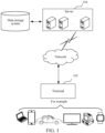
- An image noise reduction method and a filter data processing method provided in the embodiments of the present disclosure may be applied to an application environment shown in FIG. 1 .
- a terminal 102 communicates with a server 104 through a network.
- a data storage system may store data that the server 104 needs to process, for example, may store a target noise reduction image obtained by performing noise reduction.
- the data storage system may be integrated on the server 104, or may be placed on a cloud or another server.
- the server may be an independent physical server, or may be a server cluster including a plurality of physical servers or a distributed system, or may be a cloud server providing basic cloud computing services, such as a cloud service, a cloud database, cloud computing, a cloud function, cloud storage, a network service, cloud communication, a middleware service, a domain name service, a security service, a CDN, big data, and an artificial intelligence platform.
- the terminal may be a smart phone, a tablet computer, a notebook computer, a desktop computer, an intelligent voice interaction device, a smart home appliance, an in-vehicle terminal, an aircraft, or the like, but is not limited thereto.
- the terminal and the server may be directly or indirectly connected in a wired or wireless communication manner. This is not limited in the present disclosure.
- the image noise reduction method and the filter data processing method provided in the embodiments of the present disclosure may be performed by the terminal 102, or may be performed by the server 104, or may be collaboratively performed by the terminal 102 and the server 104.
- the terminal 102 may acquire a first image, and send the first image to the server.
- the server further obtains a reference image corresponding to the first image; then determines motion intensity parameter of a first block in the first image according to the reference image; obtains filter coefficient mapping information matching the motion intensity parameter, where the filter coefficient mapping information is configured for describing a correspondence between a pixel difference and a filter coefficient representation value; obtains a target pixel difference between a pixel point in the first block and a pixel point at a corresponding position in the reference image, to determine, based on the filter coefficient mapping information, a target filter coefficient representation value that has a correspondence with the target pixel difference; and determines a target noise reduction image corresponding to the first image based on the target filter coefficient representation value.
- the server 104 may return the target noise reduction image to the terminal 102.
- an image noise reduction method is provided, and is performed by a computer device.
- the computer device may be the terminal 102 in FIG. 1 , or may be the server 104 in FIG. 1 , or may be a system formed by the terminal 102 and the server 104.
- the image noise reduction method includes the following steps.
- Step 202 Obtain, from a video, a first image and a reference image, a reference timestamp of the reference image in the video is earlier than a first timestamp of the first image in the video.
- the first image is an image on which noise reduction needs to be performed.
- the first image may be an image acquired by the computer device, or an image that is received by the computer device through a network and that is acquired by another computer device.
- the first image may be a video frame in a video.
- the reference image is an image used as a reference for performing time domain filtering on the first image.
- the reference image and the first image may include a same foreground object.
- the reference image may be an image obtained through noise reduction processing.
- the reference image may be an image obtained by performing noise reduction processing on a forward video frame of the first image.
- the noise reduction processing herein may be time domain filtering processing or spatial filtering processing. In other embodiments, the noise reduction processing may alternatively first perform time domain filtering, and then perform spatial filtering processing.
- the computer device may obtain one or more reference images corresponding to the first image, and then may perform filtering processing on the first image based on the reference image, to implement noise reduction of the first image.
- "A plurality of" mentioned in the embodiments of the present disclosure is at least two.
- the obtaining a first image and a reference image includes: determining a first video on which noise reduction is to be performed; using a video frame in the first video as a first image, and determining a first video frame from a forward video frame corresponding to the first image; and obtaining a target noise reduction image corresponding to the first video frame, and determining the target noise reduction image corresponding to the first video frame as a reference image corresponding to the first image.
- the first video on which noise reduction is to be performed is a video on which noise reduction processing needs to be performed.
- the forward video frame corresponding to the first image is a video frame whose time point is before that of the first image in the first video. For example, if the first image is a video frame at a 10 th second in the first video, a video frame before the 10 th second in the first video is the forward video frame of the first image.
- the target noise reduction image corresponding to the first video frame is a target noise reduction image obtained when the first video frame is used as the first image.
- noise reduction may be performed through recursive filtering.
- a target noise reduction image of each frame of video frame obtained by using the image noise reduction method in the present disclosure may be saved to be used as a reference image of a backward video frame of the video frame. It may be understood that, a backward video frame of a video frame is a video frame whose corresponding time point is after that of the video frame.
- the computer device may sequentially determine various video frames after a first frame in the first video as first images. For each first image, the computer device may determine one or more first video frames from a forward video frame corresponding to the first image, obtain a target noise reduction image corresponding to the first video frame, and use the target noise reduction image as a reference image corresponding to the first image.
- a video application program may be installed on the computer device.
- the video application program may be used to shoot to obtain a video, or play and edit a video.
- the video application program may be, for example, a live streaming application program, a video editing application program, a video surveillance application program, a video conferencing application program, and the like.
- the computer device may sequentially use the video frames as first images, and obtain a reference image of the first image, so that a target noise reduction image of the first image can be obtained through the image noise reduction method provided in the present disclosure, to improve visual quality of the video, and obtain better user experience.
- the application program herein may be a client installed on the terminal, and the client (which may also be referred to as an application client or an APP client) is a program installed and run on the terminal; the application program may also be an installation-free application program, that is, an application program that can be used without downloading and installing.
- Such application programs are also commonly referred to as applets, which are usually run on a client as subprograms; the application program may also be a web application program opened through a browser; and the like.
- FIG. 3 is a schematic diagram of an interface in which an image noise reduction algorithm in the present disclosure is applied to a video conferencing application program.
- the video conferencing application program may use the image noise reduction method provided in the present disclosure to perform noise reduction processing on each video frame in a conference video generated in a conference scenario.
- a correlation between video frames that are closely spaced in time is greater than a correlation between video frames that are far apart in time
- using video frames that are closely spaced in time as first video frames to obtain a reference image can improve a noise reduction effect.
- the computer device selects a first video frame, one or a preset quantity of video frames adjacent to a first image in a forward video frame of the first image may be used as the first video frame, where the preset quantity is less than a preset threshold, the preset quantity may be, for example, 2.
- a third frame of video frame and a fourth frame of video frame may be used as first video frames, and target noise reduction images of the third frame of video frame and the fourth frame of video frame are respectively obtained as a reference image of the fifth frame of video frame.
- Step 204 Obtain, for each of first pixels in the first image, a first pixel value difference, based on first pixel value of the respective first pixel and a reference pixel value of a corresponding one of reference pixels in the reference image, the respective first pixel and the corresponding reference pixel relating to a same pixel position.
- Step 206 Determine, for each of a plurality of first blocks obtained by dividing the first image, a motion intensity parameter based on block difference between the respective first block and a corresponding one of a plurality of reference blocks, the block difference being obtained based on the first pixel value differences of first pixels in the respective first block, the reference blocks being obtained by dividing the reference image, the respective first block and the corresponding reference block relating to a same pixel area.
- the first block is an image block obtained by dividing the first image.
- a plurality of image blocks may be obtained by dividing the first image, and each image block may be used as a first block.
- the motion intensity parameter may represent a motion amount of the first block relative to the reference image.
- the motion intensity parameter is negatively correlated with noise intensity of the first block relative to the reference image, and is positively correlated with a difference degree of the first block relative to the reference image.
- a motion-adaptive time domain filtering manner is used. When a large motion amount in the current frame is detected, a weight of the current frame is increased, and a proportion of the previous frame is weakened.
- the current frame after fusion 0.05*previous two frames+0.05*previous frame+0.9*current frame, so that a smear problem can be alleviated.
- motion intensity parameter of different areas in a video frame is often very different, for example, in a picture at a specific moment, only a character moves while a background is still, if motion intensity parameter calculation is performed on an entire frame of image, weak time domain filtering intensity is selected, resulting in a poor noise reduction effect of a background area.
- the first image may be divided to obtain the plurality of image blocks, each image block is used as the first block, and motion intensity parameter of each first block is estimated according to the reference image, to use different time domain filters in different image blocks according to estimated motion levels, so that there can still be a good noise reduction effect on the fixed background when the character moves.
- an even division manner may be used to evenly divide the first image to obtain a plurality of first blocks. Specifically, if a height and a width of the first image are H and W respectively, and the entire image is set to be divided into m rows and n columns, a height and a width of each block are H/m and W/n respectively.
- FIG. 4 is a schematic diagram of dividing a first image according to a specific embodiment. Referring to FIG. 4 , each small grid is one first block. It may be understood that, in other embodiments, the computer device may also unevenly divide or overlappingly divide the first image. A specific division manner is not limited in the present disclosure.
- the server may perform motion intensity parameter calculation based on each reference image, so that motion intensity parameter can be obtained for each first block.
- Step 208 Obtain, for each motion intensity parameter, a piece of filter coefficient mapping information, the filter coefficient mapping information describing a mapping relationship between the first pixel value differences and filter coefficient representation values.
- the filter coefficient representation value is a value for representing a filter coefficient, and the filter coefficient representation value may be specifically a filter coefficient value or a value obtained by performing specific calculation on the filter coefficient value.
- a weighting coefficient k ranges from 0 to 1, and has the following relationship:
- a pixel difference (where the pixel difference herein represents an absolute value of the difference between the two) between a current input Y ( i,j ) and the time domain filtering result Y out ( t- 1) ( i,j ) at the previous moment is larger indicates k is smaller; otherwise, k is larger, so the filter coefficient k is negatively correlated with the difference between Y out (t- 1) ( i,j ) and Y ( i,j ) .
- the correspondence between the pixel difference and the filter coefficient representation value may be established and saved as the filter coefficient mapping information, to determine the filter coefficient representation value based on the filter coefficient mapping information, and determine a time domain filtering result obtained by performing time domain filtering on the first image through the filter coefficient representation value.
- the present disclosure uses the motion-adaptive filtering manner, and different filtering effects are expected to be obtained under different motion intensity parameter: Larger motion intensity parameter indicates that a filtering effect is to be weaker, and smaller motion intensity parameter indicates that a filtering effect is to be appropriately enhanced. Therefore, in the present disclosure, a plurality of pieces of filter coefficient mapping information may be predetermined, change degrees of filter coefficient representation values in different pieces of filter coefficient mapping information are different, and the change degree of the filter coefficient representation value is set to be positively correlated with the motion intensity parameter.
- the change degree of the filter coefficient representation value is a change degree of the filter coefficient representation value as the pixel difference changes.
- larger motion intensity parameter indicates a larger change degree of the filter coefficient representation value, and in this case, the filter coefficient representation value rapidly decreases as the pixel difference increases; otherwise, smaller motion intensity parameter indicates a smaller change degree of the filter coefficient representation value, and in this case, a decreasing degree of the filter coefficient representation value may become slower as the pixel difference increases.
- the filter coefficient mapping information may be a filter function.
- the filter coefficient value is a dependent variable
- the pixel difference is an independent variable.
- the filter function may be a decreasing exponential function of the filter coefficient about the pixel difference.
- the computer device may divide the motion intensity parameter into a plurality of intervals, and set, in each interval, a corresponding filter function: Stronger motion indicates a steeper curve of the filter function. In this way, smear in a motion area can be avoided, and an image block with weak motion uses a relatively gentle filter curve, so that a better noise reduction effect can be achieved on a relatively fixed background.
- the filter function may be an exponential function. For example, FIG.
- FIG. 5 is a schematic diagram of a filter function according to an embodiment.
- the motion intensity parameter is divided into two intervals, where a part less than a preset motion intensity parameter threshold is divided into a small motion intensity parameter interval, and a part greater than the preset motion intensity parameter threshold is divided into a large motion intensity parameter interval.
- a designed filter function is shown as a dotted line in FIG. 5 .
- a designed filter function is shown as a solid line in FIG. 5 . It can be seen from FIG. 5 that, a function curve corresponding to large motion intensity parameter is steeper than a function curve corresponding to small motion intensity parameter.
- the computer device pre-saves the plurality of pieces of filter coefficient mapping information, where each piece of filter coefficient mapping information corresponds to one piece of reference motion intensity parameter information.
- the computer device may determine reference motion intensity parameter information matching the motion intensity parameter of the first block from a plurality of pieces of reference motion intensity parameter information, to obtain filter coefficient mapping information corresponding to the reference motion intensity parameter information as the filter coefficient mapping information matching the motion intensity parameter.
- a plurality of pieces of motion intensity parameter may be obtained for each first block.
- the computer device needs to obtain matched filter coefficient mapping information.
- Step 210 Process each of the plurality of first blocks to obtain a corresponding second block, based on a plurality of target filter coefficient representation values, each relating to the corresponding first pixel, the target filter coefficient representation value being obtained based on the respective first pixel value difference and a corresponding filter coefficient mapping information.
- the computer device may calculate a difference between the pixel point and a pixel point at a corresponding position in the reference image, and use an absolute value of the difference as a target pixel difference, to determine, based on the filter coefficient mapping information, a target filter coefficient representation value that has a correspondence with the target pixel difference.
- the computer device may determine, based on each piece of filter coefficient mapping information, a target filter coefficient representation value that has a correspondence with the target pixel difference, so that a plurality of target filter coefficient representation values can be obtained for each pixel point.
- the computer device may substitute a target pixel difference into the filter function, and a calculated function value is a target filter coefficient representation value corresponding to the target pixel difference.
- Step 212 Obtaining a second image based on the second blocks.
- the computer device may determine, based on the target filter coefficient representation values corresponding to each pixel point, an intermediate processed image obtained by performing time domain filtering on the first image, to obtain the target noise reduction image corresponding to the first image based on the intermediate processed image.
- the computer device may refer to the foregoing Formula (1); perform time domain filtering on each pixel point based on the target filter coefficient representation values corresponding to each pixel point in the first block, to obtain a time domain filtering result of each pixel point; and update the first image by using the time domain filtering result of each pixel point as a current pixel value in the first image, to obtain the intermediate processed image.
- the computer device may directly use the intermediate processed image as the target noise reduction image corresponding to the first image.
- the computer device can continue to use spatial filtering after a time domain operation, and use an image obtained through spatial filtering processing as the target noise reduction image.
- the spatial filtering herein is a smoothing method. A principle thereof is that pixel values of a natural image are relatively smooth and continuous in space, a shot image is a natural image with noise added, and a purpose of using spatial filtering is to eliminate unsmooth noise, to obtain a smooth natural image.
- the spatial filtering may use at least one of Gaussian filtering and bilateral filtering.
- the computer device may obtain a trained deep learning model for spatial filtering, input the intermediate processed image into the deep learning model, and output the target noise reduction image through the deep learning model.
- the deep learning model for spatial filtering may be trained using a supervised training method. Input samples in a training process are original images without spatial filtering, and training labels are target images obtained through spatial filtering.
- motion intensity parameter of a first block in a first image is determined according to a reference image; filter coefficient mapping information matching the motion intensity parameter is obtained; a target pixel difference between a pixel point in the first block and a pixel point at a corresponding position in the reference image is obtained, to determine, based on the filter coefficient mapping information, a target filter coefficient representation value that has a correspondence with the target pixel difference; and a target noise reduction image corresponding to the first image is determined based on the target filter coefficient representation value. Because the first block is obtained by dividing the first image, different target filter coefficient representation values may be determined for different first blocks in the first image, and the obtained target filter coefficient representation values may accurately match motion conditions of various areas in the image.
- the target filter coefficient representation value is determined through the filter coefficient mapping information, the filter coefficient mapping information is configured for describing a correspondence between a pixel difference and a filter coefficient representation value, the filter coefficient representation value is negatively correlated with the pixel difference, and a change degree of the filter coefficient representation value is positively correlated with the motion intensity parameter. Therefore, for each pixel point, a target filter coefficient representation value matching the pixel point can be obtained, further improving the noise reduction effect of the first image.
- the foregoing method further includes: obtaining multiple parameter intervals of the motion intensity parameter, and a pixel value difference distribution range; determining multiple mapping relationships between the first pixel value differences and the filter coefficient, each corresponding to the parameter interval, the first pixel value difference being in the pixel value difference distribution range; determining multiple pieces of the filter coefficient mapping information based on the multiple mapping relationships; and the obtaining, for the each motion intensity parameter, a piece of filter coefficient mapping information comprises: determining a first parameter interval from the multiple parameter intervals of the motion intensity parameter, to determine the piece of filter coefficient mapping information corresponding to the first parameter interval.
- the reference motion intensity parameter information is information used as a reference for determining the filter coefficient mapping information.
- the reference motion intensity parameter information may be a motion intensity parameter interval or a specific value.
- the pixel difference distribution range is a range in which all possible pixel differences are distributed, and the pixel difference distribution range may be [0, 255].
- the computer device determines, on a premise of ensuring that the filter coefficient representation value is negatively correlated with the pixel difference and the change degree of the filter coefficient representation value is positively correlated with the motion intensity parameter, filter coefficient representation values under various possible pixel differences in the pixel difference distribution range. For example, assuming that pixel differences are integers, for each piece of reference motion intensity parameter information, the computer device may determine filter coefficient representation values under a total of 256 pixel differences including 0, 1, 2, ... in [0, 255].
- the computer device may establish the correspondence between each filter coefficient representation value and the corresponding pixel difference; form, from such correspondences, the filter coefficient mapping information by using the correspondences of the filter coefficient representation values determined based on the same piece of reference motion intensity parameter information; and use the filter coefficient mapping information as the filter coefficient mapping information corresponding to the reference motion intensity parameter information, to obtain the filter coefficient mapping information corresponding to each reference motion intensity parameter information.
- a correspondence determined based on X1 is (0, b1 0 ), (1, b1 1 ), and (255, b1 255 )
- a correspondence determined based on X2 is (0, b2 0 ), (1, b2 1 ), and (255, b2 255 ), where b indicates a pixel difference.
- the computer device may form filter coefficient mapping information corresponding to X1 by using (0, b1 0 ), (1, b1 1 ), and (255, b1 255 ), and form filter coefficient mapping information corresponding to X2 by using (0, b2 0 ), (1, b2 1 ), and (255, b2 255 ).
- the computer device may store the correspondence in a form of the following table, where an index value of the table is a pixel difference. Referring to Table 1, for example, when a target pixel difference is 3, a filter coefficient representation value is 0.88. Table 1 1 0.96 0.92 0.88 0.84 0.80 0.23 0.20 0.18 ...
- the computer device may further establish the correspondence between each piece of reference motion intensity parameter information and the corresponding filter coefficient mapping information. Based on the correspondence, when the filter coefficient mapping information matching the motion intensity parameter of the first block needs to be obtained, the computer device may determine the target motion intensity parameter information matching the motion intensity parameter from the plurality of pieces of reference motion intensity parameter information, to determine the filter coefficient mapping information that has a correspondence with the target motion intensity parameter information as the filter coefficient mapping information matching the motion intensity parameter.
- the reference motion intensity parameter information may be specific reference motion intensity parameter, and is a specific value.
- the computer device may determine, in the plurality of pieces of reference motion intensity parameter, reference motion intensity parameter with a smallest difference from the motion intensity parameter as target reference motion intensity parameter, to determine filter coefficient mapping information that has a correspondence with the target reference motion intensity parameter as the filter coefficient mapping information matching the motion intensity parameter. For example, assuming that reference motion intensity parameter information includes 10, 20, and 30, if motion intensity parameter of a first block is 12, it may be determined that corresponding reference motion intensity parameter information is 10, to determine filter coefficient mapping information corresponding to 10 as filter coefficient mapping information matching the motion intensity parameter.
- the computer device may set a larger quantity of pieces of reference motion intensity parameter, and establish a correspondence between each piece of filter coefficient mapping information and a plurality of pieces of reference motion intensity parameter, so that the established correspondence is more accurate.
- the computer device may set 10, 12, 14, 16, 18, 20, 22, 24, 26, 28, and 30; establish a correspondence between 10, 12, 14, and 16, and first filter coefficient mapping information; establish a correspondence between 18, 20, 22, 24, and 26, and second filter coefficient mapping information; and establish a correspondence between 28 and 30, and third filter coefficient mapping information.
- filter coefficient mapping information describes a correspondence between a pixel difference and a filter coefficient representation value under each piece of reference motion intensity parameter information
- a pixel difference corresponding to a pixel point in the first image may be directly used as an index, and a corresponding filter coefficient representation value may be queried from the filter coefficient mapping information. This avoids obtaining a filter coefficient through complex calculation, and improves filtering efficiency.
- the determining, multiple mapping relationships between the first pixel value differences and the filter coefficient comprises: determining, based on each parameter interval, filter coefficients under the plurality of pixel differences in the pixel difference distribution range, the filter coefficient being negatively correlated with the pixel value difference, and a rate of change of the filter coefficient being positively correlated with the motion intensity parameter; and multiplying each filter coefficient by a corresponding pixel difference, to obtain a filter coefficient representation value under each pixel difference; and the processing each of the plurality of first blocks to obtain a corresponding second block comprises: determining a time domain filtering result of the pixel point based on a size relationship between the first pixel value of the first pixel and the reference pixel value of a corresponding reference pixel at the corresponding position in the reference image, to determine the second block corresponding to the first block based on the time domain filtering result of the pixel point.
- the computer device may first determine, based on each piece of reference motion intensity parameter information, the target filter coefficients under the plurality of pixel differences in the pixel difference distribution range; and ensure, when determining the target filter coefficients, that the filter coefficient representation value is negatively correlated with the pixel difference, and the change degree of the filter coefficient representation value is positively correlated with the motion intensity parameter.
- each target filter coefficient is multiplied by the corresponding pixel difference, to obtain the filter coefficient representation value under each pixel difference, that is, ( Y out ( t- 1) ( i,j ) -Y ( i,j ) ) *k is used as the filter coefficient representation value.
- Table 2 a filter coefficient representation value obtained by multiplying each filter coefficient by a corresponding pixel difference is shown in Table 2 below.
- an index value is also a pixel difference.
- a filter coefficient representation value obtained by looking up the table may be as 3.36. Table 2 0 0.96 1.84 2.64 3.36 4.0 1.38 1.40 1.44 ...
- the pixel difference multiplied with the target filter coefficient herein is an absolute value of the pixel difference. Therefore, whether an actual calculation result of ( Y out ( t- 1) ( i,j ) -Y ( i,j ) ) *k is a positive value or a negative value needs to be determined based on the size relationship between the pixel value of the pixel point and the pixel value of the pixel point at the corresponding position in the reference image.
- the determining a time domain filtering result of the pixel point based on a size relationship between the first pixel value of the first pixel and the reference pixel value of a corresponding reference pixel at the corresponding position in the reference image, to determine the second block corresponding to the first block based on the time domain filtering result of the pixel point comprises: subtracting, in a case that the first pixel value of the first pixel is greater than or equal to the reference pixel value of a corresponding reference pixel, the target filter coefficient representation value from the first pixel value of the first pixel, to obtain the time domain filtering result of the pixel point; and adding, in a case that the first pixel value of the first pixel is less than or equal to the reference pixel value of a corresponding reference pixel, the first pixel value of the first pixel to the target filter coefficient representation value, to obtain the time domain filtering result of the pixel point.
- the computer device updates a pixel value in the first image by using the time domain filtering result, to obtain an intermediate processed image.
- the computer device may determine the target noise reduction image corresponding to the first image based on the intermediate processed image.
- the determining a plurality of pieces of reference motion intensity parameter information includes: dividing a motion intensity distribution range into multiple parameter intervals, and using each motion intensity parameter interval as one piece of reference motion intensity parameter information; and the determining target motion intensity parameter information matching the motion intensity parameter from the plurality of pieces of reference motion intensity parameter information, to determine filter coefficient mapping information corresponding to the target motion intensity parameter information as the filter coefficient mapping information matching the motion intensity parameter includes: determining a target interval to which the motion intensity parameter belongs from the plurality of motion intensity parameter intervals, and determining filter coefficient mapping information corresponding to the target interval as the filter coefficient mapping information matching the motion intensity parameter.
- the motion intensity parameter distribution range is a range in which all possible motion intensity parameter are distributed.
- the computer device may divide the motion intensity parameter distribution range into a plurality of intervals to obtain the plurality of motion intensity parameter intervals, use each motion intensity parameter interval as one piece of reference motion intensity parameter information, and establish a correspondence between the motion intensity parameter interval and filter coefficient mapping information.
- the computer device may determine which motion intensity parameter interval the motion intensity parameter belongs to, determine the motion intensity parameter interval to which the motion intensity parameter belongs as the target interval, obtain the filter coefficient mapping information that has a correspondence with the target interval, and determine the filter coefficient mapping information as the filter coefficient mapping information matching the motion intensity parameter.
- the motion intensity parameter distribution range is [a, b], and the motion intensity parameter distribution range may be divided into three intervals, namely, [a, c], (c, d), and [d, b], where a ⁇ c ⁇ d ⁇ b. If specific motion intensity parameter of the first block belongs to (c, d), (c, d) may be determined as the target interval, and the corresponding filter coefficient mapping information may be determined as the filter coefficient mapping information matching the motion intensity parameter.
- a motion intensity parameter distribution range is divided into a plurality of intervals, and each motion intensity parameter interval is used as one piece of reference motion intensity parameter information, so that matched filter coefficient mapping information can be determined through a motion intensity parameter interval to which the motion intensity parameter belongs, thereby improving accuracy of the determined filter coefficient mapping information.
- the method before the determining, for each of a plurality of first blocks obtained by dividing the first image, a motion intensity parameter based on block difference between the respective first block and a corresponding one of a plurality of reference blocks, the method further comprises: converting three primary color channel data in the first image into luma channel data, chroma channel data, and concentration channel data, and extracting the luma channel data; and converting three primary color channel data in the reference image into luma channel data, chroma channel data, and concentration channel data, and extracting the luma channel data; the determining, for each of a plurality of first blocks obtained by dividing the first image, a motion intensity parameter based on block difference between the respective first block and a corresponding one of a plurality of reference blocks comprises: determining the motion intensity parameter of the first block according to the luma channel data of the reference image and luma channel data of the first block; the obtaining, for each of first pixels in the first image, a first pixel value difference comprises: obtaining the
- RGB model a manner of recording an image by recording red, green, and blue intensity of each pixel.
- PNG and BMP are based on the RGB model.
- a YUV model which is also referred to as a luma-chroma model.
- the YUV model is a model that records an image by converting RGB three channels into one channel (Y, also referred to as Luma) indicating luma and two channels (UV, also referred to as Chroma) indicating chroma through mathematical conversion.
- Y indicates a luma channel value
- U indicates a chroma channel value
- V indicates a concentration channel value
- R indicates an R-channel value
- G indicates a G-channel value
- B indicates a B-channel value.
- a U channel and a V channel may be transformed in a same manner by referring to the Y channel. Amplified values are rounded. After such transformations, the floating-point operations become integer multiplication and displacement operations, the displacement operation is very efficient, and the integer multiplication operation is also more efficient than the floating-point operations, so that obtained Y-channel data, U-channel data, and V-channel data are all integer values.
- the computer device may convert the three primary color channel data in the first image into Y-channel data, U-channel data, and V-channel data, extract only the Y-channel data, and perform noise reduction processing on the Y-channel data; and similarly convert the three primary color channel data in the reference image into Y-channel data, U-channel data, and V-channel data, and extract only the Y-channel data.
- the computer device may determine motion intensity parameter of the luma channel data of the first block according to the luma channel data of the reference image; obtain the pixel difference between the pixel point in the first block and the pixel point at the corresponding position in the reference image under the luma channel data, to obtain the target pixel difference; and finally determine, based on the target filter coefficient representation value, the target noise reduction image obtained by performing noise reduction processing on the luma channel data of the first image.
- a first image is converted from an RGB domain to a YUV domain, and then noise reduction processing is performed on only a luma channel Y, so that an amount of calculation in a noise reduction process is reduced, and image noise reduction efficiency is improved.
- the determining, based on the target filter coefficient representation values, the second block obtained by performing noise reduction processing on the luma channel data of the first block comprises: determining, based on the target filter coefficient representation value, intermediate processed data obtained by performing time domain filtering on the luma channel data of the first block; performing spatial noise reduction based on the intermediate processed data, to obtain target luma data corresponding to the first block; and combining and converting the target luma data, and the chroma channel data and the concentration channel data of the first block into three primary color channel data, to obtain the second block.
- the computer device may determine the intermediate processed data obtained by performing time domain filtering on the luma channel data of the first image; may further perform spatial noise reduction based on the intermediate processed data, to obtain the target luma data under a luma channel; and may finally combine and convert the target luma data, and the chroma channel data and the concentration channel data separated from the first image into the three primary color channel data, to obtain the target noise reduction image.
- the Y-channel data, U-channel data, and V-channel data are further combined and converted into RGB data, so that an obtained target noise reduction image can better meet needs.
- the image noise reduction method further includes: determining a luma representation value of the first block based on the luma channel data of the first block; entering, in a case that the luma representation value is less than or equal to a preset luma threshold, the operation of determining the motion intensity parameter of the first block according to the luma channel data of the reference image and luma channel data of the first block, and using, in a case that the luma representation value is greater than the preset luma threshold, the luma channel data of the first block as the intermediate processed data, and entering the operation of performing spatial noise reduction based on the intermediate processed data, to obtain target luma data corresponding to the first block.
- the luma representation value is configured for representing entire luma of the first block.
- the luma representation value may be obtained by collecting statistics on Y-channel values of pixel points in the first block, and the statistics collection herein may be one of summing, averaging, or finding a median.
- a luma representation value of a first block is obtained through statistics collection, and no time domain noise reduction processing is performed on a first block whose luma representation value is greater than a specific threshold, to achieve a purpose of saving performance.
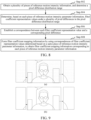
- FIG. 6 is a schematic specific flowchart of an image noise reduction method. The method specifically includes the following steps.
- Step 602 Convert RGB into YUV and extract a Y channel.
- a computer device may convert a first image from an RGB format to a YUV format, and extract Y-channel data therein; and convert a reference image from an RGB format to a YUV format, and extract Y-channel data therein.
- Step 604 Perform block division.
- the computer device may divide the first image, to obtain a plurality of first blocks.
- Step 606 Determine whether a luma mean in a block exceeds a threshold; enter step 612 if the luma mean in the block exceeds the threshold; and perform step 608 if the luma mean in the block does not exceed the threshold.
- the computer device calculates a luma mean of each first block. For each first block, if the luma mean is greater than the luma threshold, step 612 is entered; and if the luma mean is less than or equal to the luma threshold, step 608 is entered.
- Step 608 Estimate in-block motion intensity parameter.
- the computer device may determine motion intensity parameter of the first block based on the Y-channel data of the reference image.
- Step 610 Select, in different blocks, different time domain filters according to motion intensity parameter.
- the computer device may obtain filter coefficient mapping information matching the motion intensity parameter.
- the computer device may obtain a target pixel difference between the pixel point and a pixel point at a corresponding position in the reference image, and determine, based on the filter coefficient mapping information, a target filter coefficient representation value that has a correspondence with the target pixel difference, so that a target filter coefficient representation value of each pixel point can be obtained.
- the computer device may determine, based on each target filter coefficient representation value, a time domain filtering result obtained by performing time domain filtering on Y-channel data of each pixel point in the first block. Time domain filtering results of the pixel points form intermediate processed data of the first block.
- Step 612 Combine the divided blocks.
- Step 614 Perform spatial filtering.
- the computer device may combine intermediate processed data of the first blocks, including intermediate processed data of a first block whose luma mean is greater than the preset luma threshold, and intermediate processed data of a first block whose luma mean is less than or equal to the preset luma threshold; and perform spatial noise reduction on intermediate processed data obtained through combination, to obtain target luma data corresponding to the first image. Because no time domain noise reduction processing is performed on the first block whose luma mean is greater than the preset luma threshold, the intermediate processed data is original luma channel data of the first block.
- Step 616 Combine the Y channel and UV channels, and complete conversion from YUV to RGB.
- the computer device combines and converts the target luma data, U-channel data, and V-channel data into an RGB format, to finally obtain the target noise reduction image.
- time domain noise reduction processing is performed on only Y-channel data, and no time domain noise reduction is performed on a first block whose luma mean is greater than a preset luma threshold, so that performance of a computer device is saved while a noise reduction effect is met, thereby avoiding waste of performance.
- the difference degree is configured for representing a difference size of the first block relative to the reference image.
- a larger difference indicates a larger difference degree.
- the noise intensity is configured for representing a noise level of the first block relative to the reference image. Greater noise indicates larger noise intensity.
- the difference degree may be obtained by collecting statistics on pixel differences of moving pixel points in the first block relative to the reference image. The statistics collection may be specifically summing, averaging, or finding a median.
- the noise intensity may be obtained by collecting statistics on pixel differences of noise pixel points in the first block relative to the reference image according to a statistics collection manner the same as that of the difference degree.
- the moving pixel points and the noise pixel points in the first block may be distinguished through change ranges relative to the reference image.
- a pixel point with a pixel difference greater than a preset threshold may be determined as a moving pixel point, and a pixel point with a pixel difference less than or equal to the preset threshold may be determined as a noise pixel point.
- the computer device may determine a difference degree of the first block relative to an image block at a corresponding position in the reference image, and noise intensity of the first block relative to the image block at the corresponding position in the reference image; and determine the motion intensity parameter of the first block based on the difference degree and the noise intensity.
- the motion intensity parameter is positively correlated with the difference degree, and the motion intensity parameter is negatively correlated with the noise intensity.
- the positive correlation means that when other conditions remain unchanged, two variables change in a same direction; and when one variable changes from large to small, the other variable also changes from large to small.
- the positive correlation herein means that change directions are consistent, but it does not require that when one variable changes a little, the other variable also necessarily changes. For example, it may be set that, when a variable a ranges from 10 to 20, a variable b is 100; and when the variable a ranges from 20 to 30, the variable b is 120. In this way, change directions of a and b are that when a becomes larger, b also becomes larger. However, when a is in the range of 10 to 20, b may not change.
- the negative correlation means that when one variable changes from large to small, the other variable also changes from small to large, that is, change directions of the two variables are opposite.
- a larger difference degree indicates larger motion intensity parameter, and a smaller difference degree indicates smaller motion intensity parameter; and larger noise intensity indicates smaller motion intensity parameter, and smaller noise intensity indicates larger motion intensity parameter.
- motion intensity parameter of a first block may be determined based on a difference degree and noise intensity, the motion intensity parameter is positively correlated with the difference degree, and the motion intensity parameter is negatively correlated with the noise intensity, so that the motion intensity parameter can accurately reflect a noise situation of a first image, thereby improving accuracy of image noise reduction.
- the determining a difference degree of the first block relative to the reference block, and noise intensity of the first block relative to the reference block comprises: obtaining a pixel difference of each first pixel points in the first block relative to the reference pixel point at a corresponding position in the reference block; determining a noise pixel point and a moving pixel point in the first block based on the pixel difference corresponding to each first pixel point, the moving pixel point being a pixel point with a pixel difference greater than a preset difference threshold, and the noise pixel point being a pixel point with a pixel difference less than or equal to the preset difference threshold; and collecting statistics on a pixel difference of each noise pixel point to obtain the noise intensity, and collecting statistics on a pixel difference of each moving pixel point to obtain the difference degree.
- a difference threshold N may be preset. For each pixel point in the first block, when the pixel difference of the pixel point relative to the pixel point at the corresponding position in the reference image is less than or equal to the preset difference threshold, it indicates that the pixel point at the position has no large pixel value difference in previous and next frames, and is likely to be a noise signal; and in this case, the computer device may determine the pixel point as a noise pixel point.
- the computer device may determine the pixel point as a moving pixel point.
- the computer device may collect statistics on the pixel difference of each noise pixel point in the first block to obtain the noise intensity. For example, the computer device may add the pixel difference of each noise pixel point to obtain the noise intensity.
- the computer device may collect statistics on the pixel difference of each moving pixel point in the first block to obtain the difference degree. For example, the computer device may add the pixel difference of each moving pixel point to obtain the difference degree.
- the pixel difference is an absolute difference.
- a pixel value of a pixel point in the first block is X
- a pixel value of a pixel point that has a position correspondence with the pixel point in the reference image is Y
- a pixel difference is
- a noise pixel point and a moving pixel point are determined based on a size relationship between a pixel difference and a preset difference threshold, so that noise intensity may be obtained by collecting statistics on a pixel difference of each noise pixel point, and a difference degree may be obtained by collecting statistics on a pixel difference of each moving pixel point. Because a pixel difference can reflect whether a pixel point at each position moves, accuracy of motion intensity parameter calculation is improved.
- the determining the obtaining a second image based on the second blocks comprises: Combining multiple second blocks, to obtain an input block and a guide block; down-sampling the input image to obtain a first sampled image, and down-sampling the guide image to obtain a second sampled image; performing guided filtering on the first sampled image based on the second sampled image, to obtain a third image; and up-sampling the third image according to a size of the input image, to obtain the second image with a same size as the input image.
- the computer device uses the intermediate processed image as the input image and the guide image respectively; further down-samples the input image, so that the input image is reduced according to a target scaling ratio, to obtain the first sampled image, and down-samples the guide image, so that the guide image is reduced according to the target scaling ratio, to obtain the second sampled image; and then performs guided filtering on the first sampled image based on the second sampled image, to obtain the target image, where the target image is still an image with a size reduced. Therefore, the computer device further up-samples the target image according to the size of the input image, so that the target image is enlarged according to the target scaling ratio, to obtain the target noise reduction image with the same size as the input image.
- the image noise reduction method in the present disclosure may be applied in an architecture shown in FIG. 7 .
- Images in an image sequence acquired by a camera are sequentially used as first images.
- video encoding is performed to obtain encoded data, and the encoded data is sent to a cloud.
- the cloud decodes the video data, a decoded video stream is presented to a user.
- the computer device may also decode the encoded data locally, and present the decoded video stream to the user.
- the camera may be from a built-in camera of the computer device or from an external camera. An original image acquired by the camera includes a noise signal.
- the present disclosure further provides a filter data processing method, and the method is performed by a computer device.
- the computer device may be the terminal 102 in FIG. 1 , or may be the server 104 in FIG. 1 , or may be a system formed by the terminal 102 and the server 104.
- the filter data processing method includes the following steps.
- Step 802 Obtain a plurality of pieces of reference motion intensity parameter information, and determine a pixel difference distribution range.
- Step 804 Determine, based on each piece of reference motion intensity parameter information, filter coefficient representation values under a plurality of pixel differences in the pixel difference distribution range.
- the reference motion intensity parameter information is information used as a reference for determining filter coefficient mapping information.
- the reference motion intensity parameter information may be a motion intensity parameter interval or a specific value.
- the pixel difference distribution range is a range in which all possible pixel differences are distributed, and the pixel difference distribution range may be [0, 255].
- the computer device determines, on a premise of ensuring that the filter coefficient representation value is negatively correlated with the pixel difference and a change degree of the filter coefficient representation value is positively correlated with motion intensity parameter, filter coefficient representation values under various possible pixel differences in the pixel difference distribution range.
- Step 806 Establish a correspondence between each filter coefficient representation value and a corresponding pixel difference.
- the filter coefficient mapping information is configured for performing time domain filtering on a first image.
- the computer device may establish the correspondence between each filter coefficient representation value and the corresponding pixel difference; form, from such correspondences, the filter coefficient mapping information by using the correspondences of the filter coefficient representation values determined based on the same piece of reference motion intensity parameter information; and use the filter coefficient mapping information as the filter coefficient mapping information corresponding to the reference motion intensity parameter information, to obtain the filter coefficient mapping information corresponding to each reference motion intensity parameter information.
- the computer device may further establish the correspondence between each piece of reference motion intensity parameter information and the corresponding filter coefficient mapping information. Based on the correspondence, when time domain filtering needs to be performed on the first image, and filter coefficient mapping information matching motion intensity parameter of a first block in the first image may be obtained, the computer device may determine target motion intensity parameter information matching the motion intensity parameter from the plurality of pieces of reference motion intensity parameter information, to determine filter coefficient mapping information that has a correspondence with the target motion intensity parameter information as the filter coefficient mapping information matching the motion intensity parameter, so that time domain filtering may be determined to be performed on the first image based on the filter coefficient mapping information.
- filter coefficient mapping information describes a correspondence between a pixel difference and a filter coefficient representation value under each piece of reference motion intensity parameter information
- a pixel difference corresponding to a pixel point in the first image may be directly used as an index, and a corresponding filter coefficient representation value may be queried from the filter coefficient mapping information. This avoids obtaining a filter coefficient through complex calculation, and improves filtering efficiency.
- the determining, based on each piece of reference motion intensity parameter information, filter coefficient representation values under a plurality of pixel differences in the pixel difference distribution range includes: determining, based on each piece of reference motion intensity parameter information, target filter coefficients under the plurality of pixel differences in the pixel difference distribution range; and multiplying each target filter coefficient by a corresponding pixel difference, to obtain a filter coefficient representation value under each pixel difference.
- the foregoing filter data processing method further includes: obtaining the first image and a reference image; determining motion intensity parameter of a first block in the first image according to the reference image, the first block being obtained by dividing the first image; obtaining filter coefficient mapping information matching the motion intensity parameter, the filter coefficient mapping information being configured for describing a correspondence between a pixel difference and a filter coefficient representation value; and the filter coefficient representation value being negatively correlated with the pixel difference, and a change degree of the filter coefficient representation value being positively correlated with the motion intensity parameter; obtaining a target pixel difference between a pixel point in the first block and a pixel point at a corresponding position in the reference image, to determine, based on the filter coefficient mapping information, a target filter coefficient representation value that has a correspondence with the target pixel difference; and determining a target noise reduction image corresponding to the first image based on the target filter coefficient representation value.
- steps in the flowcharts involved in the foregoing embodiments are displayed sequentially according to instructions of arrows, these steps are not necessarily performed sequentially according to a sequence instructed by the arrows. Unless otherwise explicitly specified in this specification, execution of the steps is not strictly limited, and the steps may be performed in other sequences.
- at least some steps in the flowcharts involved in the foregoing embodiments may include a plurality of steps or a plurality of stages, and these steps or stages are not necessarily performed at a same moment, but may be performed at different moments.
- the steps or stages are not necessarily performed in sequence, but may be performed by turn or alternately with other steps or at least part of steps or stages in other steps.
- the present disclosure further provides an application scenario.
- the image noise reduction method in the present disclosure is applied to a video conferencing application program, to perform noise reduction processing on a video frame in a video conference.
- the computer device may sequentially use, starting from a second frame, video frames in a video frame sequence obtained through shooting during the conference as first images. For each first imaged, the following steps are performed.
- the filter coefficient mapping information may be stored in a form of a table, and the pixel difference is used as an index value of the table.
- the filter coefficient mapping information may be stored in a form of a table, and the pixel difference is used as an index value of the table.
- intermediate processed data is original luma channel data of the first block.
- the present disclosure further provides another application scenario.
- the image noise reduction method in the present disclosure is applied to a video live streaming application program, to perform noise reduction processing on a video frame in a live streaming process.
- the computer device may sequentially use, starting from a second frame, video frames in a video frame sequence acquired in the live streaming process as first images.
- the image noise reduction method provided in this embodiment of the present disclosure is performed on each first image, to obtain a target noise reduction image, so that video visual quality in the live streaming process can be improved.
- filter coefficient mapping information stores a correspondence between a filter coefficient and a pixel difference.
- a computer device may query a target filter coefficient from filter coefficient mapping information matching motion intensity parameter of the first block, to calculate a time domain filtering result of each pixel point by using the foregoing Formula (1).
- a first image is divided into blocks, and statistics is collected on information such as luma, a motion degree, and noise intensity in each block, so that time domain filters with different intensity are used for different blocks, to achieve regional motion adaptive noise reduction.
- time domain filtering spatial guided filtering is performed on the image, to further eliminate residual noise, and retain edge information to avoid blurring. This can effectively resolve problems of motion smear and image blur after noise reduction with a low amount of calculation, achieving an excellent noise reduction effect.
- the following embodiments describe the noise reduction effect of the present disclosure with examples.
- FIG. 9 is a schematic diagram of an effect of an image noise reduction method according to an embodiment of the present disclosure.
- (a) in FIG. 9 is a schematic diagram of an image before noise reduction
- (b) in FIG. 9 is a schematic diagram of the image before noise reduction.
- part areas areas within boxes in the original image
- FIG. 9 the image before noise reduction includes many noise particles
- the particles are reduced, and the image becomes clear and smooth.
- a good noise reduction effect can be achieved in both a background area and a foreground area.
- FIG. 10 is a schematic diagram of an effect of an image noise reduction method according to an embodiment of the present disclosure.
- (a) in FIG. 10 is a schematic diagram of an image before noise reduction
- (b) in FIG. 10 is a schematic diagram of the image before noise reduction.
- the image before noise reduction includes noise points that frequently jitter, causing discomfort; and after noise reduction processing is performed through the image noise reduction method provided in this embodiment of the present disclosure, the jitter points disappear.
- an embodiment of the present disclosure further provides an image noise reduction apparatus configured to implement the foregoing image noise reduction method and a filter data processing apparatus configured to implement the foregoing filter data processing method.
- the solutions to the problems provided by the apparatuses are similar to the solutions described in the foregoing methods. Therefore, for specific limitations in one or more embodiments of the image noise reduction apparatus and the filter data processing apparatus provided below, refer to the limitations on the foregoing method embodiments.
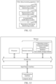
- an image noise reduction apparatus 1100 is provided, and includes:
- the target filter coefficient representation value is determined through filter coefficient mapping information, the filter coefficient mapping information is configured for describing a correspondence between a pixel difference and a filter coefficient representation value, the filter coefficient representation value is negatively correlated with the pixel difference, and a change degree of the filter coefficient representation value is positively correlated with motion intensity parameter. Therefore, for each pixel point, a target filter coefficient representation value matching the pixel point can be obtained, further improving the noise reduction effect of the first image.
- the foregoing image noise reduction apparatus further includes: a description information determining module, configured to determine a plurality of pieces of reference motion intensity parameter information, and determine a pixel difference distribution range; determine, based on each piece of reference motion intensity parameter information, filter coefficient representation values under a plurality of pixel differences in the pixel difference distribution range; establish a correspondence between each filter coefficient representation value and a corresponding pixel difference; and form filter coefficient mapping information by using correspondences of filter coefficient representation values determined based on a same piece of reference motion intensity parameter information, to obtain filter coefficient mapping information corresponding to each piece of reference motion intensity parameter information; and the description information obtaining module 1106 is further configured to determine target motion intensity parameter information matching the motion intensity parameter from the plurality of pieces of reference motion intensity parameter information, to determine filter coefficient mapping information corresponding to the target motion intensity parameter information as the filter coefficient mapping information matching the motion intensity parameter.
- a description information determining module configured to determine a plurality of pieces of reference motion intensity parameter information, and determine a pixel difference distribution range; determine, based on each piece of
- the noise reduction image determining module is further configured to subtract, when the pixel value of the pixel point is greater than or equal to the pixel value of the pixel point at the corresponding position in the reference image, the target filter coefficient representation value from the pixel value of the pixel point, to obtain the time domain filtering result of the pixel point; and add, when the pixel value of the pixel point is less than or equal to the pixel value of the pixel point at the corresponding position in the reference image, the pixel value of the pixel point to the target filter coefficient representation value, to obtain the time domain filtering result of the pixel point.
- the description information determining module is further configured to divide a motion intensity parameter distribution range into a plurality of motion intensity parameter intervals, and use each motion intensity parameter interval as one piece of reference motion intensity parameter information; and the description information obtaining module 1106 is further configured to determine a target interval to which the motion intensity parameter belongs from the plurality of motion intensity parameter intervals, and determine filter coefficient mapping information corresponding to the target interval as the filter coefficient mapping information matching the motion intensity parameter.
- the foregoing apparatus further includes a format conversion module, configured to convert three primary color channel data in the first image into luma channel data, chroma channel data, and concentration channel data, and extract the luma channel data; and convert three primary color channel data in the reference image into luma channel data, chroma channel data, and concentration channel data, and extract the luma channel data;
- the motion intensity parameter determining module is further configured to determine the motion intensity parameter of the first block according to the luma channel data of the reference image and luma channel data of the first block;
- the filter coefficient determining module is further configured to obtain a pixel difference between the pixel point in the first block and the pixel point at the corresponding position in the reference image under the luma channel data, to obtain the target pixel difference;
- the noise reduction image determining module is further configured to determine, based on the target filter coefficient representation value, the target noise reduction image obtained by performing noise reduction processing on the luma channel data of the first image.
- the noise reduction image determining module is further configured to determine, based on the target filter coefficient representation value, intermediate processed data obtained by performing time domain filtering on the luma channel data of the first image; perform spatial noise reduction based on the intermediate processed data, to obtain target luma data corresponding to the first image; and combine and convert the target luma data, and the chroma channel data and the concentration channel data of the first image into three primary color channel data, to obtain the target noise reduction image.
- the foregoing apparatus further includes: a luma representation value determining module, configured to determine a luma representation value of the first block based on the luma channel data of the first block; enter, when the luma representation value is less than or equal to a preset luma threshold, the step of determining the motion intensity parameter of the first block according to the luma channel data of the reference image and luma channel data of the first block; and use, when the luma representation value is greater than the preset luma threshold, the luma channel data of the first block as the intermediate processed data, and enter the step of performing spatial noise reduction based on the intermediate processed data, to obtain target luma data corresponding to the first image.
- a luma representation value determining module configured to determine a luma representation value of the first block based on the luma channel data of the first block; enter, when the luma representation value is less than or equal to a preset luma threshold, the step of determining the motion intensity parameter of the first block according to
- the motion intensity parameter determining module is further configured to determine a difference degree of the first block relative to the reference image, and noise intensity of the first block relative to the reference image; and determine the motion intensity parameter of the first block based on the difference degree and the noise intensity, the motion intensity parameter being positively correlated with the difference degree, and the motion intensity parameter being negatively correlated with the noise intensity.
- the motion intensity parameter determining module is further configured to obtain a pixel difference of each pixel point in the first block relative to a pixel point at a corresponding position in the reference image; determine a noise pixel point and a moving pixel point in the first block based on the pixel difference corresponding to each pixel point, the moving pixel point being a pixel point with a pixel difference greater than a preset difference threshold, and the noise pixel point being a pixel point with a pixel difference less than or equal to the preset difference threshold; and collect statistics on a pixel difference of each noise pixel point to obtain the noise intensity, and collect statistics on a pixel difference of each moving pixel point to obtain the difference degree.
- the noise reduction image determining module is further configured to determine, based on the target filter coefficient representation value, an intermediate processed image obtained by performing time domain filtering on the first image, to use the intermediate processed image as an input image and a guide image respectively; down-sample the input image to obtain a first sampled image, and down-sample the guide image to obtain a second sampled image; perform guided filtering on the first sampled image based on the second sampled image, to obtain a target image; and up-sample the target image according to a size of the input image, to obtain the target noise reduction image with a same size as the input image.
- the image obtaining module is further configured to determine a first video on which noise reduction is to be performed; use a video frame in the first video as a first image, and determine a first video frame from a forward video frame corresponding to the first image; and obtain a target noise reduction image corresponding to the first video frame, and determine the target noise reduction image corresponding to the first video frame as a reference image corresponding to the first image.
- a filter data processing apparatus 1200 includes:
- filter coefficient mapping information describes a correspondence between a pixel difference and a filter coefficient representation value under each piece of reference motion intensity parameter information
- a pixel difference corresponding to a pixel point in the first image may be directly used as an index, and a corresponding filter coefficient representation value may be queried from the filter coefficient mapping information. This avoids obtaining a filter coefficient through complex calculation, and improves filtering efficiency.
- the representation value determining module is further configured to determine, based on each piece of reference motion intensity parameter information, target filter coefficients under the plurality of pixel differences in the pixel difference distribution range; and multiplying each target filter coefficient by a corresponding pixel difference, to obtain a filter coefficient representation value under each pixel difference.
- the modules in the foregoing image noise reduction apparatus and filter data processing apparatus may be implemented entirely or partially by software, hardware, or combinations thereof.
- the foregoing modules may be built in or independent of a processor of a computer device in a hardware form, or may be stored in a memory of the computer device in a software form, so that the processor invokes and performs an operation corresponding to each of the foregoing modules.
- a computer device is provided.
- the computer device may be a server, and an internal structure diagram thereof may be shown in FIG. 13 .
- the computer device includes a processor, a memory, an input/output (I/O) interface, and a communication interface.
- the processor, the memory, and the input/output interface are connected via a system bus, and the communication interface is connected to the system bus via the input/output interface.
- the processor of the computer device is configured to provide computing and control capabilities.
- the memory of the computer device includes a non-volatile storage medium and an internal memory.
- the non-volatile storage medium stores an operating system, a computer program, and a database.
- the internal memory provides an environment for running of the operating system and the computer program in the non-volatile storage medium.
- a computer device is provided.
- the computer device may be a terminal, and an internal structure diagram thereof may be shown in FIG. 14 .
- the computer device includes a processor, a memory, an input/output interface, a communication interface, a display unit, and an input apparatus.
- the processor, the memory, and the input/output interface are connected via a system bus, and the communication interface, the display unit, and the input apparatus are connected to the system bus via the input/output interface.
- the processor of the computer device is configured to provide computing and control capabilities.
- the memory of the computer device includes a non-volatile storage medium and an internal memory.
- the non-volatile storage medium stores an operating system and a computer program.
- the internal memory provides an environment for running of the operating system and the computer program in the non-volatile storage medium.
- the input/output interface of the computer device is configured to exchange information between the processor and an external device.
- the communication interface of the computer device is configured to communicate with an external terminal in a wired or wireless manner, and the wireless manner may be implemented through WIFI, a mobile cellular network, near field communication (NFC), or other technologies.
- the computer program is executed by the processor to implement an image noise reduction method or a filter data processing method.
- the display unit of the computer device is configured to form a visually visible picture, and may be a display screen, a projection apparatus, or a virtual reality imaging apparatus.
- the display screen may be a liquid crystal display screen or an electronic ink display screen.
- the input apparatus of the computer device may be a touch layer covering the display screen, or may be a key, a trackball, or a touch pad disposed on a housing of the computer device, or may be an external keyboard, a touch pad, a mouse, or the like.
- FIG. 13 and FIG. 14 are only block diagrams of part of structures related to the solutions of the present disclosure and do not limit the computer device to which the solutions of the present disclosure is applied.
- the computer device may include more or fewer components than those in the drawings, or some components are combined, or a different component deployment is used.
- a computer device including a memory and a processor, the memory storing a computer program, and the processor, when executing the computer program, implementing steps of the foregoing image noise reduction method or filter data processing method.
- a computer-readable storage medium having a computer program stored therein, the computer program, when executed by a processor, implementing steps of the foregoing image noise reduction method or filter data processing method.
- a computer program product including a computer program, the computer program, when executed by a processor, implementing steps of the foregoing image noise reduction method or filter data processing method.
- User information including but not limited to user device information, user personal information, and the like
- data including but not limited to data used for analysis, stored data, displayed data, and the like
- a person of ordinary skill in the art may understand that some or all procedures in the foregoing method embodiments may be implemented by a computer program instructing related hardware.
- the computer program may be stored in a non-volatile computer-readable storage medium, and when the computer program is executed, the procedures of the foregoing method embodiments may be performed.
- Any reference to a memory, a database, or another medium used in the embodiments provided in the present disclosure may include at least one of a non-volatile memory and a volatile memory.
- the non-volatile memory may include a read-only memory (ROM), a magnetic tape, a floppy disk, a flash memory, an optical memory, a high-density embedded non-volatile memory, a resistive memory (ReRAM), a magnetoresistive random access memory (MRAM), a ferroelectric random access memory (FRAM), a phase change memory (PCM), a graphene memory, or the like.
- the volatile memory may include a random access memory (RAM), an external cache, or the like.
- the RAM is available in a plurality of forms, such as a static RAM (SRAM) or a dynamic RAM (DRAM).
- the database involved in the embodiments provided in the present disclosure may include at least one of a relational database and a non-relational database.
- the non-relational database may include a blockchain-based distributed database, or the like, but is not limited thereto.
- the processor involved in the embodiments provided in the present disclosure may be a general-purpose processor, a central processing unit, a graphics processor, digital signal processor, a programmable logic device, a quantum computing-based data processing logic device, or the like, but is not limited thereto.
Landscapes
- Engineering & Computer Science (AREA)
- Physics & Mathematics (AREA)
- General Physics & Mathematics (AREA)
- Theoretical Computer Science (AREA)
- Computer Vision & Pattern Recognition (AREA)
- Multimedia (AREA)
- Quality & Reliability (AREA)
- Picture Signal Circuits (AREA)
- Image Processing (AREA)
Abstract
Description
- This application claims priority to
Chinese Patent Application No. 2022105900364, entitled "IMAGE NOISE REDUCTION AND FILTER DATA PROCESSING METHOD AND APPARATUS, AND COMPUTER DEVICE" filed on May 27, 2022 - This application relates to the field of image processing technologies, and in particular, to an image noise reduction method and apparatus, a computer device, a storage medium, and a computer program product; and a filter data processing method and apparatus, a computer device, a storage medium, and a computer program product.
- With the development of image processing technologies, an image noise reduction technology emerges. The image noise reduction technology can reduce image noise information caused by hardware errors and unstable light sources. In many scenarios, image noise reduction is required. For example, during video acquisition, various types of noise are mixed in an acquired image sequence. To improve a visual effect of a video image, and improve compression efficiency of the video image or reduce a bandwidth, noise reduction is required for the video image.
- In related technologies, when noise reduction is performed on an image, there is often a problem of a poor noise reduction effect.
- According to various embodiments of the present disclosure, an image noise reduction method and apparatus, a computer device, a computer-readable storage medium, and a computer program product; and a filter data processing method and apparatus, a computer device, a computer-readable storage medium, and a computer program product are provided.
- According to an aspect, the present disclosure provides an image noise reduction method, performed by a computer device. The method includes: obtaining, from a video, a first image and a reference image, a reference timestamp of the reference image in the video is earlier than a first timestamp of the first image in the video; obtaining, for each of first pixels in the first image, a first pixel value difference, based on first pixel value of the respective first pixel and a reference pixel value of a corresponding one of reference pixels in the reference image, the respective first pixel and the corresponding reference pixel relating to a same pixel position; determining, for each of a plurality of first blocks obtained by dividing the first image, a motion intensity parameter based on block difference between the respective first block and a corresponding one of a plurality of reference blocks, the block difference being obtained based on the first pixel value differences of first pixels in the respective first block, the reference blocks being obtained by dividing the reference image, the respective first block and the corresponding reference block relating to a same pixel area; obtaining, for each motion intensity parameter, a piece of filter coefficient mapping information, the filter coefficient mapping information describing a mapping relationship between the first pixel value differences and filter coefficient representation values; processing each of the plurality of first blocks to obtain a corresponding second block, based on a plurality of target filter coefficient representation values, each relating to the corresponding first pixel, the target filter coefficient representation value being obtained based on the respective first pixel value difference and a corresponding filter coefficient mapping information (210); and obtaining a second image based on the second blocks (212).
- According to another aspect, the present disclosure further provides an image noise reduction apparatus. The apparatus includes: an image obtaining module, configured to obtain, from a video, a first image and a reference image, a reference timestamp of the reference image in the video is earlier than a first timestamp of the first image in the video; a motion intensity determining module, configured to obtain, for each of first pixels in the first image, a first pixel value difference, based on first pixel value of the respective first pixel and a reference pixel value of a corresponding one of reference pixels in the reference image, the respective first pixel and the corresponding reference pixel relating to a same pixel position, and determine, for each of a plurality of first blocks obtained by dividing the first image, a motion intensity parameter based on block difference between the respective first block and a corresponding one of a plurality of reference blocks, the block difference being obtained based on the first pixel value differences of first pixels in the respective first block, the reference blocks being obtained by dividing the reference image, the respective first block and the corresponding reference block relating to a same pixel area; a mapping information obtaining module, configured to obtain, for the each motion intensity parameter, a piece of filter coefficient mapping information, the filter coefficient mapping information describing a mapping relationship between the first pixel value differences and filter coefficient representation values; a filter coefficient determining module, configured to process each of the plurality of first blocks to obtain a corresponding second block, based on a plurality of target filter coefficient representation values, each relating to the corresponding first pixel, the target filter coefficient representation value being obtained based on the respective first pixel value difference and a corresponding filter coefficient mapping information; and a noise reduction image determining module, configured to a second image based on the second blocks.
- According to another aspect, the present disclosure further provides a computer device. The computer device includes a memory and a processor, the memory storing a computer program, and the processor, when executing the computer program, implementing steps of the foregoing image noise reduction method.
- According to another aspect, the present disclosure further provides a computer-readable storage medium. The computer-readable storage medium has a computer program stored therein, the computer program, when executed by a processor, implementing steps of the foregoing image noise reduction method.
- According to another aspect, the present disclosure further provides a computer program product. The computer program product includes a computer program, the computer program, when executed by a processor, implementing steps of the foregoing image noise reduction method.
- According to another aspect, the present disclosure provides a filter data processing method, performed by a computer device. The method includes: obtaining multiple parameter intervals of a motion intensity parameter, and a pixel value difference distribution range; determining multiple mapping relationships between the first pixel value differences and the filter coefficient, each corresponding to the parameter interval, the first pixel value difference being in the pixel value difference distribution range; and determining multiple pieces of the filter coefficient mapping information based on the multiple mapping relationships; the filter coefficient mapping information being configured for performing time domain filtering on a first image; preferably, wherein the determining multiple mapping relationships between the first pixel value differences and the filter coefficient, each corresponding to the parameter interval, the first pixel value difference being in the pixel value difference distribution range comprises: determining, based on each parameter interval, filter coefficients under the plurality of pixel differences in the pixel difference distribution range; and multiplying each filter coefficient by a corresponding pixel difference, to obtain a filter coefficient representation value under each pixel difference.
- According to another aspect, the present disclosure further provides a filter data processing apparatus. The apparatus includes: a reference motion intensity obtaining module, configured to obtain multiple parameter intervals of a motion intensity parameter, and a pixel value difference distribution range; a representation value determining module, configured to determine multiple mapping relationships between the first pixel value differences and the filter coefficient, each corresponding to the parameter interval, the first pixel value difference being in the pixel value difference distribution range; and a correspondence establishment module, configured to determine multiple pieces of the filter coefficient mapping information based on the multiple mapping relationships; the filter coefficient mapping information being configured for performing time domain filtering on a first image.
- According to another aspect, the present disclosure further provides a computer device. The computer device includes a memory and a processor, the memory storing a computer program, and the processor, when executing the computer program, implementing steps of the foregoing filter data processing method.
- According to another aspect, the present disclosure further provides a computer-readable storage medium. The computer-readable storage medium has a computer program stored therein, the computer program, when executed by a processor, implementing steps of the foregoing filter data processing method.
- According to another aspect, the present disclosure further provides a computer program product. The computer program product includes a computer program, the computer program, when executed by a processor, implementing steps of the foregoing filter data processing method.
- Details of one or more embodiments of the present disclosure are provided in the accompanying drawings and descriptions below. Other features, objectives, and advantages of the present disclosure become apparent from the specification, the accompanying drawings, and the claims.
- To describe the technical solutions in the embodiments of the present disclosure or in the conventional technology more clearly, the following briefly describes the accompanying drawings required for describing the embodiments or the conventional technology. Apparently, the accompanying drawings in the following description show only the embodiments of the present disclosure, and a person of ordinary skill in the art may derive other drawings from the disclosed accompanying drawings without creative efforts.
-
FIG. 1 is a diagram of an application environment of an image noise reduction method and a filter data processing method according to an embodiment. -
FIG. 2 is a schematic flowchart of an image noise reduction method according to an embodiment. -
FIG. 3 is a schematic diagram of an interface in which an image noise reduction algorithm is applied to a video conferencing application program according to an embodiment. -
FIG. 4 is a schematic diagram of dividing a first image according to an embodiment. -
FIG. 5 is a schematic diagram of a filter function according to an embodiment. -
FIG. 6 is a schematic specific flowchart of an image noise reduction method according to an embodiment. -
FIG. 7 is a diagram of an application architecture of an image noise reduction method according to an embodiment. -
FIG. 8 is a schematic flowchart of a filter data processing method according to an embodiment. -
FIG. 9 is a schematic diagram of an effect of an image noise reduction method according to an embodiment. -
FIG. 10 is a schematic diagram of an effect of an image noise reduction method according to another embodiment. -
FIG. 11 is a structural block diagram of an image noise reduction apparatus according to an embodiment. -
FIG. 12 is a structural block diagram of a filter data processing apparatus according to an embodiment. -
FIG. 13 is a diagram of an internal structure of a computer device according to an embodiment. -
FIG. 14 is a diagram of an internal structure of a computer device according to an embodiment. - The technical solutions in the embodiments of the present disclosure are clearly and completely described in the following with reference to the accompanying drawings in the embodiments of the present disclosure. Apparently, the described embodiments are merely some rather than all of the embodiments of the present disclosure. All other embodiments obtained by a person skilled in the art based on the embodiments of the present disclosure without creative efforts shall fall within the protection scope of the present disclosure.
- An image noise reduction method and a filter data processing method provided in the embodiments of the present disclosure may be applied to an application environment shown in
FIG. 1 . Aterminal 102 communicates with aserver 104 through a network. A data storage system may store data that theserver 104 needs to process, for example, may store a target noise reduction image obtained by performing noise reduction. The data storage system may be integrated on theserver 104, or may be placed on a cloud or another server. The server may be an independent physical server, or may be a server cluster including a plurality of physical servers or a distributed system, or may be a cloud server providing basic cloud computing services, such as a cloud service, a cloud database, cloud computing, a cloud function, cloud storage, a network service, cloud communication, a middleware service, a domain name service, a security service, a CDN, big data, and an artificial intelligence platform. The terminal may be a smart phone, a tablet computer, a notebook computer, a desktop computer, an intelligent voice interaction device, a smart home appliance, an in-vehicle terminal, an aircraft, or the like, but is not limited thereto. The terminal and the server may be directly or indirectly connected in a wired or wireless communication manner. This is not limited in the present disclosure. - It may be understood that, the image noise reduction method and the filter data processing method provided in the embodiments of the present disclosure may be performed by the
terminal 102, or may be performed by theserver 104, or may be collaboratively performed by theterminal 102 and theserver 104. For example, the terminal 102 may acquire a first image, and send the first image to the server. The server further obtains a reference image corresponding to the first image; then determines motion intensity parameter of a first block in the first image according to the reference image; obtains filter coefficient mapping information matching the motion intensity parameter, where the filter coefficient mapping information is configured for describing a correspondence between a pixel difference and a filter coefficient representation value; obtains a target pixel difference between a pixel point in the first block and a pixel point at a corresponding position in the reference image, to determine, based on the filter coefficient mapping information, a target filter coefficient representation value that has a correspondence with the target pixel difference; and determines a target noise reduction image corresponding to the first image based on the target filter coefficient representation value. Finally, theserver 104 may return the target noise reduction image to the terminal 102. - In an embodiment, as shown in
FIG. 2 , an image noise reduction method is provided, and is performed by a computer device. The computer device may be the terminal 102 inFIG. 1 , or may be theserver 104 inFIG. 1 , or may be a system formed by the terminal 102 and theserver 104. Specifically, the image noise reduction method includes the following steps. - Step 202: Obtain, from a video, a first image and a reference image, a reference timestamp of the reference image in the video is earlier than a first timestamp of the first image in the video.
- The first image is an image on which noise reduction needs to be performed. The first image may be an image acquired by the computer device, or an image that is received by the computer device through a network and that is acquired by another computer device. The first image may be a video frame in a video. The reference image is an image used as a reference for performing time domain filtering on the first image. The reference image and the first image may include a same foreground object. The reference image may be an image obtained through noise reduction processing. When the first image is an image in a first video on which noise reduction is to be performed, the reference image may be an image obtained by performing noise reduction processing on a forward video frame of the first image. The noise reduction processing herein may be time domain filtering processing or spatial filtering processing. In other embodiments, the noise reduction processing may alternatively first perform time domain filtering, and then perform spatial filtering processing.
- Specifically, after the first image is determined, the computer device may obtain one or more reference images corresponding to the first image, and then may perform filtering processing on the first image based on the reference image, to implement noise reduction of the first image. "A plurality of" mentioned in the embodiments of the present disclosure is at least two.
- In an embodiment, the obtaining a first image and a reference image includes: determining a first video on which noise reduction is to be performed; using a video frame in the first video as a first image, and determining a first video frame from a forward video frame corresponding to the first image; and obtaining a target noise reduction image corresponding to the first video frame, and determining the target noise reduction image corresponding to the first video frame as a reference image corresponding to the first image.
- The first video on which noise reduction is to be performed is a video on which noise reduction processing needs to be performed. The forward video frame corresponding to the first image is a video frame whose time point is before that of the first image in the first video. For example, if the first image is a video frame at a 10th second in the first video, a video frame before the 10th second in the first video is the forward video frame of the first image. The target noise reduction image corresponding to the first video frame is a target noise reduction image obtained when the first video frame is used as the first image. In this embodiment of the present disclosure, noise reduction may be performed through recursive filtering. A target noise reduction image of each frame of video frame obtained by using the image noise reduction method in the present disclosure may be saved to be used as a reference image of a backward video frame of the video frame. It may be understood that, a backward video frame of a video frame is a video frame whose corresponding time point is after that of the video frame.
- Specifically, the computer device may sequentially determine various video frames after a first frame in the first video as first images. For each first image, the computer device may determine one or more first video frames from a forward video frame corresponding to the first image, obtain a target noise reduction image corresponding to the first video frame, and use the target noise reduction image as a reference image corresponding to the first image.
- In a specific embodiment, a video application program may be installed on the computer device. The video application program may be used to shoot to obtain a video, or play and edit a video. The video application program may be, for example, a live streaming application program, a video editing application program, a video surveillance application program, a video conferencing application program, and the like. When the computer device performs video playback through the video application program, for various frames of video frames in a played video, the computer device may sequentially use the video frames as first images, and obtain a reference image of the first image, so that a target noise reduction image of the first image can be obtained through the image noise reduction method provided in the present disclosure, to improve visual quality of the video, and obtain better user experience. The application program herein may be a client installed on the terminal, and the client (which may also be referred to as an application client or an APP client) is a program installed and run on the terminal; the application program may also be an installation-free application program, that is, an application program that can be used without downloading and installing. Such application programs are also commonly referred to as applets, which are usually run on a client as subprograms; the application program may also be a web application program opened through a browser; and the like.
- For example,
FIG. 3 is a schematic diagram of an interface in which an image noise reduction algorithm in the present disclosure is applied to a video conferencing application program. Referring toFIG. 3 , during a video conference, when a user checks a "video noise reduction" option in an interface of the video conferencing application program, the video conferencing application program may use the image noise reduction method provided in the present disclosure to perform noise reduction processing on each video frame in a conference video generated in a conference scenario. - In an embodiment, considering that a correlation between video frames that are closely spaced in time is greater than a correlation between video frames that are far apart in time, using video frames that are closely spaced in time as first video frames to obtain a reference image can improve a noise reduction effect. In this case, when the computer device selects a first video frame, one or a preset quantity of video frames adjacent to a first image in a forward video frame of the first image may be used as the first video frame, where the preset quantity is less than a preset threshold, the preset quantity may be, for example, 2. For example, assuming that the first image is a fifth frame of video frame in the first video, a third frame of video frame and a fourth frame of video frame may be used as first video frames, and target noise reduction images of the third frame of video frame and the fourth frame of video frame are respectively obtained as a reference image of the fifth frame of video frame.
- Step 204: Obtain, for each of first pixels in the first image, a first pixel value difference, based on first pixel value of the respective first pixel and a reference pixel value of a corresponding one of reference pixels in the reference image, the respective first pixel and the corresponding reference pixel relating to a same pixel position.
- Step 206: Determine, for each of a plurality of first blocks obtained by dividing the first image, a motion intensity parameter based on block difference between the respective first block and a corresponding one of a plurality of reference blocks, the block difference being obtained based on the first pixel value differences of first pixels in the respective first block, the reference blocks being obtained by dividing the reference image, the respective first block and the corresponding reference block relating to a same pixel area.
- The first block is an image block obtained by dividing the first image. A plurality of image blocks may be obtained by dividing the first image, and each image block may be used as a first block. The motion intensity parameter may represent a motion amount of the first block relative to the reference image. The motion intensity parameter is negatively correlated with noise intensity of the first block relative to the reference image, and is positively correlated with a difference degree of the first block relative to the reference image.
- Specifically, considering that noise information presents a Gaussian distribution in time domain, for example, noise appearing at a specific position in a current frame in a video may not exist at a same position in a forward frame or may have a weak intensity value, a weighting manner may be used for image fusion, for example, a current frame after fusion=0.2*previous two frames+0.3*previous frame+0.5*current frame. In this way, although noise can be reduced, simple fusion causes significant smear in a moving scenario. Therefore, in this embodiment of the present disclosure, a motion-adaptive time domain filtering manner is used. When a large motion amount in the current frame is detected, a weight of the current frame is increased, and a proportion of the previous frame is weakened. For example, when there is a large motion amount, the current frame after fusion=0.05*previous two frames+0.05*previous frame+0.9*current frame, so that a smear problem can be alleviated. Further, considering that motion intensity parameter of different areas in a video frame is often very different, for example, in a picture at a specific moment, only a character moves while a background is still, if motion intensity parameter calculation is performed on an entire frame of image, weak time domain filtering intensity is selected, resulting in a poor noise reduction effect of a background area.
- Based on this, in this embodiment, the first image may be divided to obtain the plurality of image blocks, each image block is used as the first block, and motion intensity parameter of each first block is estimated according to the reference image, to use different time domain filters in different image blocks according to estimated motion levels, so that there can still be a good noise reduction effect on the fixed background when the character moves.
- In an embodiment, when the computer device divides the first image, an even division manner may be used to evenly divide the first image to obtain a plurality of first blocks. Specifically, if a height and a width of the first image are H and W respectively, and the entire image is set to be divided into m rows and n columns, a height and a width of each block are H/m and W/n respectively. For example,
FIG. 4 is a schematic diagram of dividing a first image according to a specific embodiment. Referring toFIG. 4 , each small grid is one first block. It may be understood that, in other embodiments, the computer device may also unevenly divide or overlappingly divide the first image. A specific division manner is not limited in the present disclosure. - In an embodiment, when there are a plurality of reference images, for each first block in the first image, the server may perform motion intensity parameter calculation based on each reference image, so that motion intensity parameter can be obtained for each first block.
- Step 208: Obtain, for each motion intensity parameter, a piece of filter coefficient mapping information, the filter coefficient mapping information describing a mapping relationship between the first pixel value differences and filter coefficient representation values.
- The filter coefficient representation value is a value for representing a filter coefficient, and the filter coefficient representation value may be specifically a filter coefficient value or a value obtained by performing specific calculation on the filter coefficient value.
- In a noise reduction process in this embodiment of the present disclosure, time domain filtering may be performed on the first block according to the following formula, where i and j are pixel position indexes in the first image, Y indicates a pixel value in the first block, Yout (t) indicates a time domain filtering result at a current moment, Yout (t-1) indicates a pixel value in the reference image, where the reference image herein uses a time domain filtering result at a moment t-1, and k indicates the filter coefficient:

- The foregoing formula indicates that the time domain filtering result at the current moment is equal to weighted fusion of an input value at the current moment and a time domain filtering result at a previous moment. A weighting coefficient k ranges from 0 to 1, and has the following relationship: A pixel difference (where the pixel difference herein represents an absolute value of the difference between the two) between a current input Y (i,j) and the time domain filtering result Yout (t-1)(i,j) at the previous moment is larger indicates k is smaller; otherwise, k is larger, so the filter coefficient k is negatively correlated with the difference between Yout (t-1)(i,j) and Y (i,j). Based on this, in this embodiment of the present disclosure, the correspondence between the pixel difference and the filter coefficient representation value may be established and saved as the filter coefficient mapping information, to determine the filter coefficient representation value based on the filter coefficient mapping information, and determine a time domain filtering result obtained by performing time domain filtering on the first image through the filter coefficient representation value.
- Further, the present disclosure uses the motion-adaptive filtering manner, and different filtering effects are expected to be obtained under different motion intensity parameter: Larger motion intensity parameter indicates that a filtering effect is to be weaker, and smaller motion intensity parameter indicates that a filtering effect is to be appropriately enhanced. Therefore, in the present disclosure, a plurality of pieces of filter coefficient mapping information may be predetermined, change degrees of filter coefficient representation values in different pieces of filter coefficient mapping information are different, and the change degree of the filter coefficient representation value is set to be positively correlated with the motion intensity parameter. The change degree of the filter coefficient representation value is a change degree of the filter coefficient representation value as the pixel difference changes. To be specific, larger motion intensity parameter indicates a larger change degree of the filter coefficient representation value, and in this case, the filter coefficient representation value rapidly decreases as the pixel difference increases; otherwise, smaller motion intensity parameter indicates a smaller change degree of the filter coefficient representation value, and in this case, a decreasing degree of the filter coefficient representation value may become slower as the pixel difference increases.
- In an embodiment, the filter coefficient mapping information may be a filter function. In the filter function, the filter coefficient value is a dependent variable, and the pixel difference is an independent variable. For example, the filter function may be a decreasing exponential function of the filter coefficient about the pixel difference. The computer device may divide the motion intensity parameter into a plurality of intervals, and set, in each interval, a corresponding filter function: Stronger motion indicates a steeper curve of the filter function. In this way, smear in a motion area can be avoided, and an image block with weak motion uses a relatively gentle filter curve, so that a better noise reduction effect can be achieved on a relatively fixed background. In a specific embodiment, the filter function may be an exponential function. For example,
FIG. 5 is a schematic diagram of a filter function according to an embodiment. In the embodiment shown inFIG. 5 , the motion intensity parameter is divided into two intervals, where a part less than a preset motion intensity parameter threshold is divided into a small motion intensity parameter interval, and a part greater than the preset motion intensity parameter threshold is divided into a large motion intensity parameter interval. For the small motion intensity parameter interval, a designed filter function is shown as a dotted line inFIG. 5 . For the large motion intensity parameter interval, a designed filter function is shown as a solid line inFIG. 5 . It can be seen fromFIG. 5 that, a function curve corresponding to large motion intensity parameter is steeper than a function curve corresponding to small motion intensity parameter. - Specifically, the computer device pre-saves the plurality of pieces of filter coefficient mapping information, where each piece of filter coefficient mapping information corresponds to one piece of reference motion intensity parameter information. During filtering, the computer device may determine reference motion intensity parameter information matching the motion intensity parameter of the first block from a plurality of pieces of reference motion intensity parameter information, to obtain filter coefficient mapping information corresponding to the reference motion intensity parameter information as the filter coefficient mapping information matching the motion intensity parameter.
- In an embodiment, when there are a plurality of reference images, a plurality of pieces of motion intensity parameter may be obtained for each first block. In this case, for each piece of motion intensity parameter corresponding to each first block, the computer device needs to obtain matched filter coefficient mapping information.
- Step 210: Process each of the plurality of first blocks to obtain a corresponding second block, based on a plurality of target filter coefficient representation values, each relating to the corresponding first pixel, the target filter coefficient representation value being obtained based on the respective first pixel value difference and a corresponding filter coefficient mapping information.
- Specifically, for each pixel point in the first block, the computer device may calculate a difference between the pixel point and a pixel point at a corresponding position in the reference image, and use an absolute value of the difference as a target pixel difference, to determine, based on the filter coefficient mapping information, a target filter coefficient representation value that has a correspondence with the target pixel difference.
- In an embodiment, when there are a plurality of reference images, because each first block corresponds to a plurality of pieces of filter coefficient mapping information, for the target pixel difference of each pixel point in the first block, the computer device may determine, based on each piece of filter coefficient mapping information, a target filter coefficient representation value that has a correspondence with the target pixel difference, so that a plurality of target filter coefficient representation values can be obtained for each pixel point.
- In an embodiment, when the filter coefficient mapping information is a filter function, the computer device may substitute a target pixel difference into the filter function, and a calculated function value is a target filter coefficient representation value corresponding to the target pixel difference.
- Step 212: Obtaining a second image based on the second blocks.
- Specifically, the computer device may determine, based on the target filter coefficient representation values corresponding to each pixel point, an intermediate processed image obtained by performing time domain filtering on the first image, to obtain the target noise reduction image corresponding to the first image based on the intermediate processed image.
- In an embodiment, when a filter coefficient representation value is a filter coefficient value, the computer device may refer to the foregoing Formula (1); perform time domain filtering on each pixel point based on the target filter coefficient representation values corresponding to each pixel point in the first block, to obtain a time domain filtering result of each pixel point; and update the first image by using the time domain filtering result of each pixel point as a current pixel value in the first image, to obtain the intermediate processed image.
- In an embodiment, after the intermediate processed image is obtained, the computer device may directly use the intermediate processed image as the target noise reduction image corresponding to the first image. In another embodiment, considering that there is still some large-amplitude noise hard to filter out after time domain filtering, the computer device can continue to use spatial filtering after a time domain operation, and use an image obtained through spatial filtering processing as the target noise reduction image. The spatial filtering herein is a smoothing method. A principle thereof is that pixel values of a natural image are relatively smooth and continuous in space, a shot image is a natural image with noise added, and a purpose of using spatial filtering is to eliminate unsmooth noise, to obtain a smooth natural image.
- In a specific embodiment, the spatial filtering may use at least one of Gaussian filtering and bilateral filtering. In another specific embodiment, the computer device may obtain a trained deep learning model for spatial filtering, input the intermediate processed image into the deep learning model, and output the target noise reduction image through the deep learning model. The deep learning model for spatial filtering may be trained using a supervised training method. Input samples in a training process are original images without spatial filtering, and training labels are target images obtained through spatial filtering.
- In the foregoing image noise reduction method, motion intensity parameter of a first block in a first image is determined according to a reference image; filter coefficient mapping information matching the motion intensity parameter is obtained; a target pixel difference between a pixel point in the first block and a pixel point at a corresponding position in the reference image is obtained, to determine, based on the filter coefficient mapping information, a target filter coefficient representation value that has a correspondence with the target pixel difference; and a target noise reduction image corresponding to the first image is determined based on the target filter coefficient representation value. Because the first block is obtained by dividing the first image, different target filter coefficient representation values may be determined for different first blocks in the first image, and the obtained target filter coefficient representation values may accurately match motion conditions of various areas in the image. In this way, a problem of a poor noise reduction effect in part areas caused when performing motion intensity parameter estimation on the entire image is avoided, and a noise reduction effect of the first image is improved. In addition, the target filter coefficient representation value is determined through the filter coefficient mapping information, the filter coefficient mapping information is configured for describing a correspondence between a pixel difference and a filter coefficient representation value, the filter coefficient representation value is negatively correlated with the pixel difference, and a change degree of the filter coefficient representation value is positively correlated with the motion intensity parameter. Therefore, for each pixel point, a target filter coefficient representation value matching the pixel point can be obtained, further improving the noise reduction effect of the first image.
- In an embodiment, the foregoing method further includes: obtaining multiple parameter intervals of the motion intensity parameter, and a pixel value difference distribution range; determining multiple mapping relationships between the first pixel value differences and the filter coefficient, each corresponding to the parameter interval, the first pixel value difference being in the pixel value difference distribution range; determining multiple pieces of the filter coefficient mapping information based on the multiple mapping relationships; and the obtaining, for the each motion intensity parameter, a piece of filter coefficient mapping information comprises: determining a first parameter interval from the multiple parameter intervals of the motion intensity parameter, to determine the piece of filter coefficient mapping information corresponding to the first parameter interval.
- The reference motion intensity parameter information is information used as a reference for determining the filter coefficient mapping information. The reference motion intensity parameter information may be a motion intensity parameter interval or a specific value. The pixel difference distribution range is a range in which all possible pixel differences are distributed, and the pixel difference distribution range may be [0, 255].
- Specifically, after the plurality of pieces of reference motion intensity parameter information are determined and the pixel difference distribution range is determined, for each piece of reference motion intensity parameter information, the computer device determines, on a premise of ensuring that the filter coefficient representation value is negatively correlated with the pixel difference and the change degree of the filter coefficient representation value is positively correlated with the motion intensity parameter, filter coefficient representation values under various possible pixel differences in the pixel difference distribution range. For example, assuming that pixel differences are integers, for each piece of reference motion intensity parameter information, the computer device may determine filter coefficient representation values under a total of 256 pixel differences including 0, 1, 2, ... in [0, 255].
- Further, the computer device may establish the correspondence between each filter coefficient representation value and the corresponding pixel difference; form, from such correspondences, the filter coefficient mapping information by using the correspondences of the filter coefficient representation values determined based on the same piece of reference motion intensity parameter information; and use the filter coefficient mapping information as the filter coefficient mapping information corresponding to the reference motion intensity parameter information, to obtain the filter coefficient mapping information corresponding to each reference motion intensity parameter information. In the foregoing example, it is assumed that there are two pieces of reference motion intensity parameter information indicated as X1 and X2, a correspondence determined based on X1 is (0, b10), (1, b11), and (255, b1255), and a correspondence determined based on X2 is (0, b20), (1, b21), and (255, b2255), where b indicates a pixel difference. In this case, the computer device may form filter coefficient mapping information corresponding to X1 by using (0, b10), (1, b11), and (255, b1255), and form filter coefficient mapping information corresponding to X2 by using (0, b20), (1, b21), and (255, b2255).
- In a specific embodiment, for each piece of filter coefficient mapping information, the computer device may store the correspondence in a form of the following table, where an index value of the table is a pixel difference. Referring to Table 1, for example, when a target pixel difference is 3, a filter coefficient representation value is 0.88.
Table 1 1 0.96 0.92 0.88 0.84 0.80 0.23 0.20 0.18 ... - The computer device may further establish the correspondence between each piece of reference motion intensity parameter information and the corresponding filter coefficient mapping information. Based on the correspondence, when the filter coefficient mapping information matching the motion intensity parameter of the first block needs to be obtained, the computer device may determine the target motion intensity parameter information matching the motion intensity parameter from the plurality of pieces of reference motion intensity parameter information, to determine the filter coefficient mapping information that has a correspondence with the target motion intensity parameter information as the filter coefficient mapping information matching the motion intensity parameter.
- In a specific embodiment, the reference motion intensity parameter information may be specific reference motion intensity parameter, and is a specific value. In this case, when determining target motion intensity parameter information matching specific motion intensity parameter, the computer device may determine, in the plurality of pieces of reference motion intensity parameter, reference motion intensity parameter with a smallest difference from the motion intensity parameter as target reference motion intensity parameter, to determine filter coefficient mapping information that has a correspondence with the target reference motion intensity parameter as the filter coefficient mapping information matching the motion intensity parameter. For example, assuming that reference motion intensity parameter information includes 10, 20, and 30, if motion intensity parameter of a first block is 12, it may be determined that corresponding reference motion intensity parameter information is 10, to determine filter coefficient mapping information corresponding to 10 as filter coefficient mapping information matching the motion intensity parameter. It may be understood that, in some other embodiments, the computer device may set a larger quantity of pieces of reference motion intensity parameter, and establish a correspondence between each piece of filter coefficient mapping information and a plurality of pieces of reference motion intensity parameter, so that the established correspondence is more accurate. For example, the computer device may set 10, 12, 14, 16, 18, 20, 22, 24, 26, 28, and 30; establish a correspondence between 10, 12, 14, and 16, and first filter coefficient mapping information; establish a correspondence between 18, 20, 22, 24, and 26, and second filter coefficient mapping information; and establish a correspondence between 28 and 30, and third filter coefficient mapping information.
- In the foregoing embodiment, because filter coefficient mapping information describes a correspondence between a pixel difference and a filter coefficient representation value under each piece of reference motion intensity parameter information, when time domain filtering is performed on a first image, a pixel difference corresponding to a pixel point in the first image may be directly used as an index, and a corresponding filter coefficient representation value may be queried from the filter coefficient mapping information. This avoids obtaining a filter coefficient through complex calculation, and improves filtering efficiency.
- In an embodiment, the determining, multiple mapping relationships between the first pixel value differences and the filter coefficient comprises: determining, based on each parameter interval, filter coefficients under the plurality of pixel differences in the pixel difference distribution range, the filter coefficient being negatively correlated with the pixel value difference, and a rate of change of the filter coefficient being positively correlated with the motion intensity parameter; and multiplying each filter coefficient by a corresponding pixel difference, to obtain a filter coefficient representation value under each pixel difference; and the processing each of the plurality of first blocks to obtain a corresponding second block comprises: determining a time domain filtering result of the pixel point based on a size relationship between the first pixel value of the first pixel and the reference pixel value of a corresponding reference pixel at the corresponding position in the reference image, to determine the second block corresponding to the first block based on the time domain filtering result of the pixel point.
- Specifically, the foregoing Formula (1) may be further transformed as follows:

- Yout (t-1)(i,j) -Y (i,j) is the pixel difference, and k is the filter coefficient. It can be seen from Formula (2) that, if (Yout (t-1)(i,j) -Y(i,j) *k is calculated in advance, the filtering result at the current moment may be calculated through simple addition and subtraction calculation, so that the filtering efficiency can be further improved. Based on this, in this embodiment, the computer device may first determine, based on each piece of reference motion intensity parameter information, the target filter coefficients under the plurality of pixel differences in the pixel difference distribution range; and ensure, when determining the target filter coefficients, that the filter coefficient representation value is negatively correlated with the pixel difference, and the change degree of the filter coefficient representation value is positively correlated with the motion intensity parameter.
- After the target filter coefficients are determined, each target filter coefficient is multiplied by the corresponding pixel difference, to obtain the filter coefficient representation value under each pixel difference, that is, (Yout (t-1)(i,j) -Y (i,j))*k is used as the filter coefficient representation value. For example, assuming that filter coefficients are stored in Table 1, a filter coefficient representation value obtained by multiplying each filter coefficient by a corresponding pixel difference is shown in Table 2 below. In Table 2, an index value is also a pixel difference. For example, assuming that a target pixel difference is 4, a filter coefficient representation value obtained by looking up the table may be as 3.36.
Table 2 0 0.96 1.84 2.64 3.36 4.0 1.38 1.40 1.44 ... - It may be understood that, the pixel difference multiplied with the target filter coefficient herein is an absolute value of the pixel difference. Therefore, whether an actual calculation result of (Yout (t-1)(i,j) -Y (i,j))*k is a positive value or a negative value needs to be determined based on the size relationship between the pixel value of the pixel point and the pixel value of the pixel point at the corresponding position in the reference image.
- In an embodiment, the determining a time domain filtering result of the pixel point based on a size relationship between the first pixel value of the first pixel and the reference pixel value of a corresponding reference pixel at the corresponding position in the reference image, to determine the second block corresponding to the first block based on the time domain filtering result of the pixel point comprises: subtracting, in a case that the first pixel value of the first pixel is greater than or equal to the reference pixel value of a corresponding reference pixel, the target filter coefficient representation value from the first pixel value of the first pixel, to obtain the time domain filtering result of the pixel point; and adding, in a case that the first pixel value of the first pixel is less than or equal to the reference pixel value of a corresponding reference pixel, the first pixel value of the first pixel to the target filter coefficient representation value, to obtain the time domain filtering result of the pixel point.
- Specifically, when the pixel value of the pixel point is greater than the pixel value of the pixel point at the corresponding position in the reference image, (Y out (t-1)(i,j) -Y (i,j))*k is a negative value, and it can be seen from Formula (2) that, the filtering result in this case is equivalent to subtracting the target filter coefficient representation value from the pixel value of the pixel point. When the pixel value of the pixel point is less than the pixel value of the pixel point at the corresponding position in the reference image, (Yout (t-1)(i,j) -Y (i,j))*k is a positive value, and the filtering result in this case is equivalent to adding the pixel value of the pixel point to the target filter coefficient representation value. When the pixel value of the pixel point is equal to the pixel value of the pixel point at the corresponding position in the reference image, that is, Yout (t-1)(i,j) =Y (i,j) , (Yout (t-1)(i,j ) -Y (i,j ))*k is 0 in this case; the computer device subtracts the target filter coefficient representation value from the pixel value of the pixel point to obtain the time domain filtering result of the pixel point, or adds the pixel value of the pixel point to the target filter coefficient representation value to obtain the time domain filtering result of the pixel point; and it can be seen that, the time domain filtering result in this case is Yout (t-1)(i,j) or Y (i,j) .
- For example, as shown in Table 2, assuming that the target pixel difference is 3 and the target filter coefficient representation value obtained by looking up the table is 2.64, when Yout (t-1)(i,j) < Y (i,j), the time domain filtering result is that Yout (t)(i,j) = Y (i,j) - 3.36 ; and when Yout (t-1)(i,j) > Y (i,j), the time domain filtering result is that Yout (t)(i,j) = Y (i,j) + 3.36.
- Further, after the time domain filtering result of each pixel point in the first image is obtained, the computer device updates a pixel value in the first image by using the time domain filtering result, to obtain an intermediate processed image. The computer device may determine the target noise reduction image corresponding to the first image based on the intermediate processed image. For details, refer to description of the foregoing embodiments.
- In the foregoing embodiment, by multiplying each target filter coefficient by a corresponding pixel difference to obtain a filter coefficient representation value under each pixel difference, a complex function operation can be converted into simple addition and subtraction calculation, further improving filtering efficiency in a time domain filtering process, so that noise reduction efficiency can be improved.
- In an embodiment, the determining a plurality of pieces of reference motion intensity parameter information includes: dividing a motion intensity distribution range into multiple parameter intervals, and using each motion intensity parameter interval as one piece of reference motion intensity parameter information; and the determining target motion intensity parameter information matching the motion intensity parameter from the plurality of pieces of reference motion intensity parameter information, to determine filter coefficient mapping information corresponding to the target motion intensity parameter information as the filter coefficient mapping information matching the motion intensity parameter includes: determining a target interval to which the motion intensity parameter belongs from the plurality of motion intensity parameter intervals, and determining filter coefficient mapping information corresponding to the target interval as the filter coefficient mapping information matching the motion intensity parameter.
- The motion intensity parameter distribution range is a range in which all possible motion intensity parameter are distributed.
- In this embodiment, the computer device may divide the motion intensity parameter distribution range into a plurality of intervals to obtain the plurality of motion intensity parameter intervals, use each motion intensity parameter interval as one piece of reference motion intensity parameter information, and establish a correspondence between the motion intensity parameter interval and filter coefficient mapping information. In this way, after determining the motion intensity parameter of the first block, the computer device may determine which motion intensity parameter interval the motion intensity parameter belongs to, determine the motion intensity parameter interval to which the motion intensity parameter belongs as the target interval, obtain the filter coefficient mapping information that has a correspondence with the target interval, and determine the filter coefficient mapping information as the filter coefficient mapping information matching the motion intensity parameter.
- For example, it is assumed that the motion intensity parameter distribution range is [a, b], and the motion intensity parameter distribution range may be divided into three intervals, namely, [a, c], (c, d), and [d, b], where a<c<d<b. If specific motion intensity parameter of the first block belongs to (c, d), (c, d) may be determined as the target interval, and the corresponding filter coefficient mapping information may be determined as the filter coefficient mapping information matching the motion intensity parameter.
- In the foregoing embodiment, a motion intensity parameter distribution range is divided into a plurality of intervals, and each motion intensity parameter interval is used as one piece of reference motion intensity parameter information, so that matched filter coefficient mapping information can be determined through a motion intensity parameter interval to which the motion intensity parameter belongs, thereby improving accuracy of the determined filter coefficient mapping information.
- In an embodiment, before the determining, for each of a plurality of first blocks obtained by dividing the first image, a motion intensity parameter based on block difference between the respective first block and a corresponding one of a plurality of reference blocks, the method further comprises: converting three primary color channel data in the first image into luma channel data, chroma channel data, and concentration channel data, and extracting the luma channel data; and converting three primary color channel data in the reference image into luma channel data, chroma channel data, and concentration channel data, and extracting the luma channel data; the determining, for each of a plurality of first blocks obtained by dividing the first image, a motion intensity parameter based on block difference between the respective first block and a corresponding one of a plurality of reference blocks comprises: determining the motion intensity parameter of the first block according to the luma channel data of the reference image and luma channel data of the first block; the obtaining, for each of first pixels in the first image, a first pixel value difference comprises: obtaining the first pixel difference between the first pixel point in the first block and the reference pixel point at the corresponding position in the reference image under the luma channel data; and the processing each of the plurality of first blocks to obtain a corresponding second block comprises: determining, based on the target filter coefficient representation values, the second block obtained by performing noise reduction processing on the luma channel data of the first block.
- Three primary color channels are three channels of red (R), green (G), and blue (B). A display technology achieves almost any color of visible light by combining the three primary colors of red, green, and blue with different intensity. In image storage, a manner of recording an image by recording red, green, and blue intensity of each pixel is an RGB model. In common image file formats, PNG and BMP are based on the RGB model. In addition to the RGB model, there is also a widely used model referred to as a YUV model, which is also referred to as a luma-chroma model. The YUV model is a model that records an image by converting RGB three channels into one channel (Y, also referred to as Luma) indicating luma and two channels (UV, also referred to as Chroma) indicating chroma through mathematical conversion.
- In a specific embodiment, it is known that formulas for converting RGB three channel data into YUV three channel data are specifically as follows:


- Y indicates a luma channel value, U indicates a chroma channel value, V indicates a concentration channel value, R indicates an R-channel value, G indicates a G-channel value, and B indicates a B-channel value.
- Considering that the foregoing Formula (3) to Formula (5) are floating-point operations, and a floating-point multiplication operation requires exponent and mantissa operations inside a computer, which is relatively time-consuming, in this embodiment, the floating point operations are transformed into integer operations through some mathematical transformations. By using a Y channel as an example, a transformation process is as follows:

- A U channel and a V channel may be transformed in a same manner by referring to the Y channel. Amplified values are rounded. After such transformations, the floating-point operations become integer multiplication and displacement operations, the displacement operation is very efficient, and the integer multiplication operation is also more efficient than the floating-point operations, so that obtained Y-channel data, U-channel data, and V-channel data are all integer values.
- In this embodiment, based on a characteristic that human eyes are more sensitive to a luma channel component in an image, the computer device may convert the three primary color channel data in the first image into Y-channel data, U-channel data, and V-channel data, extract only the Y-channel data, and perform noise reduction processing on the Y-channel data; and similarly convert the three primary color channel data in the reference image into Y-channel data, U-channel data, and V-channel data, and extract only the Y-channel data. In this way, the computer device may determine motion intensity parameter of the luma channel data of the first block according to the luma channel data of the reference image; obtain the pixel difference between the pixel point in the first block and the pixel point at the corresponding position in the reference image under the luma channel data, to obtain the target pixel difference; and finally determine, based on the target filter coefficient representation value, the target noise reduction image obtained by performing noise reduction processing on the luma channel data of the first image.
- In the foregoing embodiment, a first image is converted from an RGB domain to a YUV domain, and then noise reduction processing is performed on only a luma channel Y, so that an amount of calculation in a noise reduction process is reduced, and image noise reduction efficiency is improved.
- In an embodiment, the determining, based on the target filter coefficient representation values, the second block obtained by performing noise reduction processing on the luma channel data of the first block comprises: determining, based on the target filter coefficient representation value, intermediate processed data obtained by performing time domain filtering on the luma channel data of the first block; performing spatial noise reduction based on the intermediate processed data, to obtain target luma data corresponding to the first block; and combining and converting the target luma data, and the chroma channel data and the concentration channel data of the first block into three primary color channel data, to obtain the second block.
- In this embodiment, because the luma channel data of the first image is extracted, after the target filter coefficient representation value of each pixel point is determined, the computer device may determine the intermediate processed data obtained by performing time domain filtering on the luma channel data of the first image; may further perform spatial noise reduction based on the intermediate processed data, to obtain the target luma data under a luma channel; and may finally combine and convert the target luma data, and the chroma channel data and the concentration channel data separated from the first image into the three primary color channel data, to obtain the target noise reduction image.
- In the foregoing embodiment, after time domain and spatial noise reduction processing is performed on Y-channel data, the Y-channel data, U-channel data, and V-channel data are further combined and converted into RGB data, so that an obtained target noise reduction image can better meet needs.
- In an embodiment, the image noise reduction method further includes: determining a luma representation value of the first block based on the luma channel data of the first block; entering, in a case that the luma representation value is less than or equal to a preset luma threshold, the operation of determining the motion intensity parameter of the first block according to the luma channel data of the reference image and luma channel data of the first block, and using, in a case that the luma representation value is greater than the preset luma threshold, the luma channel data of the first block as the intermediate processed data, and entering the operation of performing spatial noise reduction based on the intermediate processed data, to obtain target luma data corresponding to the first block.
- The luma representation value is configured for representing entire luma of the first block. The luma representation value may be obtained by collecting statistics on Y-channel values of pixel points in the first block, and the statistics collection herein may be one of summing, averaging, or finding a median. In a specific embodiment, assuming that a current block is Y and a height and a width thereof are h and w, a luma representation value may be calculated by using the following Formula (6):

- According to visual characteristics, when image luma is high, a signal-to-noise ratio is very high. In this case, human eyes cannot observe a noise signal. Therefore, noise reduction on areas with high luma values brings unnecessary waste of performance. In this embodiment, a luma representation value of a first block is obtained through statistics collection, and no time domain noise reduction processing is performed on a first block whose luma representation value is greater than a specific threshold, to achieve a purpose of saving performance.
- In a specific embodiment,
FIG. 6 is a schematic specific flowchart of an image noise reduction method. The method specifically includes the following steps. - Step 602: Convert RGB into YUV and extract a Y channel.
- Specifically, a computer device may convert a first image from an RGB format to a YUV format, and extract Y-channel data therein; and convert a reference image from an RGB format to a YUV format, and extract Y-channel data therein.
- Step 604: Perform block division.
- Specifically, the computer device may divide the first image, to obtain a plurality of first blocks.
- Step 606: Determine whether a luma mean in a block exceeds a threshold; enter
step 612 if the luma mean in the block exceeds the threshold; and performstep 608 if the luma mean in the block does not exceed the threshold. - Specifically, the computer device calculates a luma mean of each first block. For each first block, if the luma mean is greater than the luma threshold,
step 612 is entered; and if the luma mean is less than or equal to the luma threshold,step 608 is entered. - Step 608: Estimate in-block motion intensity parameter.
- Specifically, for a first block whose luma mean is less than or equal to the luma threshold, the computer device may determine motion intensity parameter of the first block based on the Y-channel data of the reference image.
- Step 610: Select, in different blocks, different time domain filters according to motion intensity parameter.
- Specifically, after the motion intensity parameter of the first block is determined, the computer device may obtain filter coefficient mapping information matching the motion intensity parameter. In this way, for each pixel point in the first block whose luma mean is less than or equal to the luma threshold, the computer device may obtain a target pixel difference between the pixel point and a pixel point at a corresponding position in the reference image, and determine, based on the filter coefficient mapping information, a target filter coefficient representation value that has a correspondence with the target pixel difference, so that a target filter coefficient representation value of each pixel point can be obtained. The computer device may determine, based on each target filter coefficient representation value, a time domain filtering result obtained by performing time domain filtering on Y-channel data of each pixel point in the first block. Time domain filtering results of the pixel points form intermediate processed data of the first block.
- Step 612: Combine the divided blocks.
- Step 614: Perform spatial filtering.
- Specifically, the computer device may combine intermediate processed data of the first blocks, including intermediate processed data of a first block whose luma mean is greater than the preset luma threshold, and intermediate processed data of a first block whose luma mean is less than or equal to the preset luma threshold; and perform spatial noise reduction on intermediate processed data obtained through combination, to obtain target luma data corresponding to the first image. Because no time domain noise reduction processing is performed on the first block whose luma mean is greater than the preset luma threshold, the intermediate processed data is original luma channel data of the first block.
- Step 616: Combine the Y channel and UV channels, and complete conversion from YUV to RGB.
- Specifically, the computer device combines and converts the target luma data, U-channel data, and V-channel data into an RGB format, to finally obtain the target noise reduction image.
- In the foregoing embodiment, when data in an RGB format is converted into data in a YUV format, time domain noise reduction processing is performed on only Y-channel data, and no time domain noise reduction is performed on a first block whose luma mean is greater than a preset luma threshold, so that performance of a computer device is saved while a noise reduction effect is met, thereby avoiding waste of performance.
- In an embodiment, the determining, for each of a plurality of first blocks obtained by dividing the first image, a motion intensity parameter based on block difference between the respective first block and a corresponding one of a plurality of reference blocks comprises: determining a difference degree of the first block relative to the reference block, and noise intensity of the first block relative to the reference block; and determining the motion intensity parameter of the first block based on the difference degree and the noise intensity, the motion intensity parameter being positively correlated with the difference degree, and the motion intensity being negatively correlated with the noise intensity.
- The difference degree is configured for representing a difference size of the first block relative to the reference image. A larger difference indicates a larger difference degree. The noise intensity is configured for representing a noise level of the first block relative to the reference image. Greater noise indicates larger noise intensity. In an embodiment, the difference degree may be obtained by collecting statistics on pixel differences of moving pixel points in the first block relative to the reference image. The statistics collection may be specifically summing, averaging, or finding a median. The noise intensity may be obtained by collecting statistics on pixel differences of noise pixel points in the first block relative to the reference image according to a statistics collection manner the same as that of the difference degree. In specific applications, the moving pixel points and the noise pixel points in the first block may be distinguished through change ranges relative to the reference image. For example, a pixel point with a pixel difference greater than a preset threshold may be determined as a moving pixel point, and a pixel point with a pixel difference less than or equal to the preset threshold may be determined as a noise pixel point.
- Specifically, for the first block in the first image, the computer device may determine a difference degree of the first block relative to an image block at a corresponding position in the reference image, and noise intensity of the first block relative to the image block at the corresponding position in the reference image; and determine the motion intensity parameter of the first block based on the difference degree and the noise intensity. The motion intensity parameter is positively correlated with the difference degree, and the motion intensity parameter is negatively correlated with the noise intensity.
- The positive correlation means that when other conditions remain unchanged, two variables change in a same direction; and when one variable changes from large to small, the other variable also changes from large to small. It may be understood that, the positive correlation herein means that change directions are consistent, but it does not require that when one variable changes a little, the other variable also necessarily changes. For example, it may be set that, when a variable a ranges from 10 to 20, a variable b is 100; and when the variable a ranges from 20 to 30, the variable b is 120. In this way, change directions of a and b are that when a becomes larger, b also becomes larger. However, when a is in the range of 10 to 20, b may not change. The negative correlation means that when one variable changes from large to small, the other variable also changes from small to large, that is, change directions of the two variables are opposite.
- It can be seen that, in this embodiment, a larger difference degree indicates larger motion intensity parameter, and a smaller difference degree indicates smaller motion intensity parameter; and larger noise intensity indicates smaller motion intensity parameter, and smaller noise intensity indicates larger motion intensity parameter.
- In an embodiment, the computer device may obtain the motion intensity parameter by calculating a ratio of the difference degree to the noise intensity, that is, motion intensity parameter=difference degree/noise intensity.
- In the foregoing embodiment, motion intensity parameter of a first block may be determined based on a difference degree and noise intensity, the motion intensity parameter is positively correlated with the difference degree, and the motion intensity parameter is negatively correlated with the noise intensity, so that the motion intensity parameter can accurately reflect a noise situation of a first image, thereby improving accuracy of image noise reduction.
- In an embodiment, the determining a difference degree of the first block relative to the reference block, and noise intensity of the first block relative to the reference block comprises: obtaining a pixel difference of each first pixel points in the first block relative to the reference pixel point at a corresponding position in the reference block; determining a noise pixel point and a moving pixel point in the first block based on the pixel difference corresponding to each first pixel point, the moving pixel point being a pixel point with a pixel difference greater than a preset difference threshold, and the noise pixel point being a pixel point with a pixel difference less than or equal to the preset difference threshold; and collecting statistics on a pixel difference of each noise pixel point to obtain the noise intensity, and collecting statistics on a pixel difference of each moving pixel point to obtain the difference degree.
- For a pixel point in the first image, a pixel point that has a position correspondence with the pixel point in the reference image is a pixel point with same pixel coordinates as the pixel point. For example, assuming that pixel coordinates of a pixel point in the first image are (x1, y1), pixel coordinates of a pixel point that has a position correspondence with the pixel point in the reference image are also (x1, y1) in the reference image.
- Specifically, considering that a motion range of noise is generally relatively small, in this embodiment, a difference threshold N may be preset. For each pixel point in the first block, when the pixel difference of the pixel point relative to the pixel point at the corresponding position in the reference image is less than or equal to the preset difference threshold, it indicates that the pixel point at the position has no large pixel value difference in previous and next frames, and is likely to be a noise signal; and in this case, the computer device may determine the pixel point as a noise pixel point. Otherwise, when the pixel difference of the pixel point relative to the pixel point at the corresponding position in the reference image is greater than the preset difference threshold, it indicates that the pixel point at the position may move, and in this case, the computer device may determine the pixel point as a moving pixel point.
- The computer device may collect statistics on the pixel difference of each noise pixel point in the first block to obtain the noise intensity. For example, the computer device may add the pixel difference of each noise pixel point to obtain the noise intensity. The computer device may collect statistics on the pixel difference of each moving pixel point in the first block to obtain the difference degree. For example, the computer device may add the pixel difference of each moving pixel point to obtain the difference degree.
- In this embodiment, for each pixel point in the first block, when the computer device obtains the pixel difference of the pixel point relative to the pixel point at the corresponding position in the reference image, the pixel difference is an absolute difference. To be specific, assuming that a pixel value of a pixel point in the first block is X, and a pixel value of a pixel point that has a position correspondence with the pixel point in the reference image is Y, a pixel difference is |X-Y|.
- In the foregoing embodiment, a noise pixel point and a moving pixel point are determined based on a size relationship between a pixel difference and a preset difference threshold, so that noise intensity may be obtained by collecting statistics on a pixel difference of each noise pixel point, and a difference degree may be obtained by collecting statistics on a pixel difference of each moving pixel point. Because a pixel difference can reflect whether a pixel point at each position moves, accuracy of motion intensity parameter calculation is improved.
- In an embodiment, the determining the obtaining a second image based on the second blocks comprises: Combining multiple second blocks, to obtain an input block and a guide block; down-sampling the input image to obtain a first sampled image, and down-sampling the guide image to obtain a second sampled image; performing guided filtering on the first sampled image based on the second sampled image, to obtain a third image; and up-sampling the third image according to a size of the input image, to obtain the second image with a same size as the input image.
- In this embodiment, after the intermediate processed image is obtained, the computer device uses the intermediate processed image as the input image and the guide image respectively; further down-samples the input image, so that the input image is reduced according to a target scaling ratio, to obtain the first sampled image, and down-samples the guide image, so that the guide image is reduced according to the target scaling ratio, to obtain the second sampled image; and then performs guided filtering on the first sampled image based on the second sampled image, to obtain the target image, where the target image is still an image with a size reduced. Therefore, the computer device further up-samples the target image according to the size of the input image, so that the target image is enlarged according to the target scaling ratio, to obtain the target noise reduction image with the same size as the input image.
- In the foregoing embodiment, when performing guided filtering, because an input image and a guide image are a same image, details can be retained at edges of the image, and smoothing is performed in flat areas, thereby avoiding an image blur problem caused by noise reduction as much as possible. In addition, because the input image and the guide image are down-sampled in the filtering process, computational complexity in the filtering process can be reduced, and costs of noise reduction are reduced.
- In a specific embodiment, the image noise reduction method in the present disclosure may be applied in an architecture shown in
FIG. 7 . Images in an image sequence acquired by a camera are sequentially used as first images. After the target noise reduction image is obtained through the image noise reduction method provided in the present disclosure, video encoding is performed to obtain encoded data, and the encoded data is sent to a cloud. After the cloud decodes the video data, a decoded video stream is presented to a user. In addition, the computer device may also decode the encoded data locally, and present the decoded video stream to the user. The camera may be from a built-in camera of the computer device or from an external camera. An original image acquired by the camera includes a noise signal. Through image noise reduction processing in the present disclosure, a clean image can be produced, thereby improving image quality. In addition, because noise is filtered out, and there is no need to encode irregular noise signals in a subsequent video encoding process, a smaller encoded file can be produced, reducing a bandwidth and storage space. - In an embodiment, as shown in
FIG. 8 , the present disclosure further provides a filter data processing method, and the method is performed by a computer device. The computer device may be the terminal 102 inFIG. 1 , or may be theserver 104 inFIG. 1 , or may be a system formed by the terminal 102 and theserver 104. Specifically, the filter data processing method includes the following steps. - Step 802: Obtain a plurality of pieces of reference motion intensity parameter information, and determine a pixel difference distribution range.
- Step 804: Determine, based on each piece of reference motion intensity parameter information, filter coefficient representation values under a plurality of pixel differences in the pixel difference distribution range.
- The reference motion intensity parameter information is information used as a reference for determining filter coefficient mapping information. The reference motion intensity parameter information may be a motion intensity parameter interval or a specific value. The pixel difference distribution range is a range in which all possible pixel differences are distributed, and the pixel difference distribution range may be [0, 255].
- Specifically, after the plurality of pieces of reference motion intensity parameter information are obtained and the pixel difference distribution range is determined, for each piece of reference motion intensity parameter information, the computer device determines, on a premise of ensuring that the filter coefficient representation value is negatively correlated with the pixel difference and a change degree of the filter coefficient representation value is positively correlated with motion intensity parameter, filter coefficient representation values under various possible pixel differences in the pixel difference distribution range.
- Step 806: Establish a correspondence between each filter coefficient representation value and a corresponding pixel difference.
- Step 808: Form filter coefficient mapping information by using correspondences of filter coefficient representation values determined based on a same piece of reference motion intensity parameter information, to obtain filter coefficient mapping information corresponding to each piece of reference motion intensity parameter information.
- The filter coefficient mapping information is configured for performing time domain filtering on a first image.
- Specifically, the computer device may establish the correspondence between each filter coefficient representation value and the corresponding pixel difference; form, from such correspondences, the filter coefficient mapping information by using the correspondences of the filter coefficient representation values determined based on the same piece of reference motion intensity parameter information; and use the filter coefficient mapping information as the filter coefficient mapping information corresponding to the reference motion intensity parameter information, to obtain the filter coefficient mapping information corresponding to each reference motion intensity parameter information.
- In an embodiment, the computer device may further establish the correspondence between each piece of reference motion intensity parameter information and the corresponding filter coefficient mapping information. Based on the correspondence, when time domain filtering needs to be performed on the first image, and filter coefficient mapping information matching motion intensity parameter of a first block in the first image may be obtained, the computer device may determine target motion intensity parameter information matching the motion intensity parameter from the plurality of pieces of reference motion intensity parameter information, to determine filter coefficient mapping information that has a correspondence with the target motion intensity parameter information as the filter coefficient mapping information matching the motion intensity parameter, so that time domain filtering may be determined to be performed on the first image based on the filter coefficient mapping information.
- In the foregoing filter data processing method, because filter coefficient mapping information describes a correspondence between a pixel difference and a filter coefficient representation value under each piece of reference motion intensity parameter information, when time domain filtering is performed on a first image, a pixel difference corresponding to a pixel point in the first image may be directly used as an index, and a corresponding filter coefficient representation value may be queried from the filter coefficient mapping information. This avoids obtaining a filter coefficient through complex calculation, and improves filtering efficiency.
- In an embodiment, the determining, based on each piece of reference motion intensity parameter information, filter coefficient representation values under a plurality of pixel differences in the pixel difference distribution range includes: determining, based on each piece of reference motion intensity parameter information, target filter coefficients under the plurality of pixel differences in the pixel difference distribution range; and multiplying each target filter coefficient by a corresponding pixel difference, to obtain a filter coefficient representation value under each pixel difference.
- In an embodiment, the foregoing filter data processing method further includes: obtaining the first image and a reference image; determining motion intensity parameter of a first block in the first image according to the reference image, the first block being obtained by dividing the first image; obtaining filter coefficient mapping information matching the motion intensity parameter, the filter coefficient mapping information being configured for describing a correspondence between a pixel difference and a filter coefficient representation value; and the filter coefficient representation value being negatively correlated with the pixel difference, and a change degree of the filter coefficient representation value being positively correlated with the motion intensity parameter; obtaining a target pixel difference between a pixel point in the first block and a pixel point at a corresponding position in the reference image, to determine, based on the filter coefficient mapping information, a target filter coefficient representation value that has a correspondence with the target pixel difference; and determining a target noise reduction image corresponding to the first image based on the target filter coefficient representation value.
- For a detailed description of this embodiment, refer to the corresponding description in the foregoing embodiment. This is not described in the present disclosure.
- Although steps in the flowcharts involved in the foregoing embodiments are displayed sequentially according to instructions of arrows, these steps are not necessarily performed sequentially according to a sequence instructed by the arrows. Unless otherwise explicitly specified in this specification, execution of the steps is not strictly limited, and the steps may be performed in other sequences. In addition, at least some steps in the flowcharts involved in the foregoing embodiments may include a plurality of steps or a plurality of stages, and these steps or stages are not necessarily performed at a same moment, but may be performed at different moments. The steps or stages are not necessarily performed in sequence, but may be performed by turn or alternately with other steps or at least part of steps or stages in other steps.
- In an embodiment, the present disclosure further provides an application scenario. In the application scenario, the image noise reduction method in the present disclosure is applied to a video conferencing application program, to perform noise reduction processing on a video frame in a video conference. Specifically, the computer device may sequentially use, starting from a second frame, video frames in a video frame sequence obtained through shooting during the conference as first images. For each first imaged, the following steps are performed.
- 1. Convert the first image from an RGB format to a YUV format.
- 2. Evenly divide the first image, to obtain a plurality of first blocks.
Specifically, assuming that a height and a width of the first image are H and W respectively, and the first image may be divided into m rows and n columns, a height and a width of each block are H/m and W/n respectively. - 3. Use each first block in the first image as a current first block; and for a current first block Y, collect statistics on a luma mean in the first block Y, and determine whether the luma mean exceeds a preset luma threshold. When the luma mean exceeds the preset luma threshold, it indicates that luma of the first block is very high and human eyes cannot observe noise, and in this case, the first block does not need to be processed and step 9 is directly entered. Otherwise, subsequent time domain noise reduction is required, and step 4 is entered.
- 4. Estimate in-block motion intensity parameter. First, for each first block, a frame difference D between a current moment (current frame) t and a previous moment (previous frame) t-1 is calculated, which may be formulated as D(t)=|Y(t)-Y(t-1)|. Considering that amplitude of noise is generally relatively small, a noise threshold N is artificially set, and (i, j) is set as a position index. When D(t) i,j ≤ N, it indicates that a pixel point at the coordinates (i, j) has no large pixel value difference in previous and next frames, and is likely to be a noise pixel point. Otherwise, when D(t) i,j > N, it indicates that the pixel point at the position is likely to move. Matrices VN and VS are defined. VN is configured for indicating a change range of a noise pixel point, and VS is configured for indicating a change range of a moving pixel point. Matrix sizes of VN and VS are consistent with that of the current first block Y. When D(t) i,j ≤ N, VNi,j = D(t) i,j and VSi,j = 0 . When D(t) i,j > N, VNi,j = 0 and VSi,j = D(t) i,j . Finally, motion intensity parameter S of the first block may be calculated by using the following Formula (7):

- 5. Determine a target interval to which the motion intensity parameter belongs from a plurality of motion intensity parameter intervals, and determine filter coefficient mapping information corresponding to the target interval as filter coefficient mapping information matching the motion intensity parameter.
- The filter coefficient mapping information is obtained in advance through the following steps and is stored in a form of a table:
- 5.1. Divide a motion intensity parameter distribution range, to obtain a plurality of motion intensity parameter intervals.
- 5.2. Determine a pixel difference distribution range; and determine, based on each motion intensity parameter interval, target filter coefficients under a plurality of pixel differences in the pixel difference distribution range.
The pixel difference distribution range is [0, 255], and the plurality of pixel differences in the pixel difference distribution range are various integer values in [0, 255]. When the target filter coefficient is determined, it is ensured that the filter coefficient is negatively correlated with the pixel difference, and a change degree of the filter coefficient is positively correlated with a motion intensity parameter value in the motion intensity parameter interval. - 5.3. Multiply each target filter coefficient by a corresponding pixel difference, to obtain a filter coefficient representation value under each pixel difference.
- 5.4. Establish a correspondence between each filter coefficient representation value and a corresponding pixel difference.
- 5.5. Form filter coefficient mapping information by using correspondences of filter coefficient representation values determined based on a same motion intensity parameter interval, to obtain filter coefficient mapping information corresponding to each motion intensity parameter interval.
- Specifically, the filter coefficient mapping information may be stored in a form of a table, and the pixel difference is used as an index value of the table. For details, refer to the foregoing Table 2.
- 6. Obtain a target pixel difference between each pixel point in the current first block and a pixel point at a corresponding position in a reference image, and use each target pixel difference as an index value, to query, from the filter coefficient mapping information matching the motion intensity parameter of the current first block, a target filter coefficient representation value that has a correspondence with each target pixel difference.
- The reference image is an intermediate processed image corresponding to a video frame at a moment t-1 (that is, a previous frame), that is, an image obtained by performing time domain filtering on the first image when the video frame at the moment t-1 is used as the first image. In this embodiment, a time domain filtering process uses recursive filtering. For each frame of video frame, after an intermediate processed image outputted through time domain filtering is obtained by using the image noise reduction method provided in this embodiment, the intermediate processed image is saved as a reference image of a next frame of video frame.
- 7. For each pixel point in the current first block, subtract, when the pixel value of the pixel point is greater than or equal to the pixel value of the pixel point at the corresponding position in the reference image, the target filter coefficient representation value from the pixel value of the pixel point, to obtain a time domain filtering result of the pixel point; and add, when the pixel value of the pixel point is less than or equal to the pixel value of the pixel point at the corresponding position in the reference image, the pixel value of the pixel point to the target filter coefficient representation value, to obtain the time domain filtering result of the pixel point.
- 8. Determine, based on a time domain filtering result of each pixel point, intermediate processed data obtained by performing time domain filtering on the current first block.
- 9. Combine intermediate processed data of each first block, and perform spatial noise reduction on intermediate processed data obtained through combination, to obtain target luma data corresponding to the first image.
- Because no time domain noise reduction processing is performed on a first block whose luma mean is greater than a preset luma threshold, intermediate processed data is original luma channel data of the first block.
- It may be understood that, an image formed by the intermediate processed data obtained through combination is the intermediate processed image corresponding to the first image, and the intermediate processed image may be saved as a reference image of a next frame of first image.
- 10. Combine and convert the target luma data, and U-channel data and V-channel data of the first image into RGB data, to obtain a target noise reduction image.
- In another embodiment, the present disclosure further provides another application scenario. In the application scenario, the image noise reduction method in the present disclosure is applied to a video live streaming application program, to perform noise reduction processing on a video frame in a live streaming process. specifically, the computer device may sequentially use, starting from a second frame, video frames in a video frame sequence acquired in the live streaming process as first images. The image noise reduction method provided in this embodiment of the present disclosure is performed on each first image, to obtain a target noise reduction image, so that video visual quality in the live streaming process can be improved. In this embodiment, filter coefficient mapping information stores a correspondence between a filter coefficient and a pixel difference. For each pixel point in a first block whose luma mean is greater than or equal to a preset luma mean, after a pixel difference corresponding to each pixel point is obtained, a computer device may query a target filter coefficient from filter coefficient mapping information matching motion intensity parameter of the first block, to calculate a time domain filtering result of each pixel point by using the foregoing Formula (1).
- Based on the foregoing embodiments, it can be seen that, in the image noise reduction method in the present disclosure, a first image is divided into blocks, and statistics is collected on information such as luma, a motion degree, and noise intensity in each block, so that time domain filters with different intensity are used for different blocks, to achieve regional motion adaptive noise reduction. After time domain filtering, spatial guided filtering is performed on the image, to further eliminate residual noise, and retain edge information to avoid blurring. This can effectively resolve problems of motion smear and image blur after noise reduction with a low amount of calculation, achieving an excellent noise reduction effect. The following embodiments describe the noise reduction effect of the present disclosure with examples.
- In a specific embodiment,
FIG. 9 is a schematic diagram of an effect of an image noise reduction method according to an embodiment of the present disclosure. (a) inFIG. 9 is a schematic diagram of an image before noise reduction, and (b) inFIG. 9 is a schematic diagram of the image before noise reduction. To better present the effect, part areas (areas within boxes in the original image) are enlarged inFIG. 9 . It can be seen fromFIG. 9 that, the image before noise reduction includes many noise particles, and after noise reduction processing is performed through the image noise reduction method provided in this embodiment of the present disclosure, the particles are reduced, and the image becomes clear and smooth. In addition, through the image noise reduction method provided in this embodiment of the present disclosure, a good noise reduction effect can be achieved in both a background area and a foreground area. - In a specific embodiment,
FIG. 10 is a schematic diagram of an effect of an image noise reduction method according to an embodiment of the present disclosure. (a) inFIG. 10 is a schematic diagram of an image before noise reduction, and (b) inFIG. 10 is a schematic diagram of the image before noise reduction. It can be seen fromFIG. 10 that, the image before noise reduction includes noise points that frequently jitter, causing discomfort; and after noise reduction processing is performed through the image noise reduction method provided in this embodiment of the present disclosure, the jitter points disappear. - Based on the same inventive concept, an embodiment of the present disclosure further provides an image noise reduction apparatus configured to implement the foregoing image noise reduction method and a filter data processing apparatus configured to implement the foregoing filter data processing method. The solutions to the problems provided by the apparatuses are similar to the solutions described in the foregoing methods. Therefore, for specific limitations in one or more embodiments of the image noise reduction apparatus and the filter data processing apparatus provided below, refer to the limitations on the foregoing method embodiments.
- In an embodiment, as shown in
FIG. 11 , an image noise reduction apparatus 1100 is provided, and includes: - an
image obtaining module 1102, configured to obtain, from a video, a first image and a reference image, a reference timestamp of the reference image in the video is earlier than a first timestamp of the first image in the video; - a motion intensity
parameter determining module 1104, configured to obtain, for each of first pixels in the first image, a first pixel value difference, based on first pixel value of the respective first pixel and a reference pixel value of a corresponding one of reference pixels in the reference image, the respective first pixel and the corresponding reference pixel relating to a same pixel position, and determine, for each of a plurality of first blocks obtained by dividing the first image, a motion intensity parameter based on block difference between the respective first block and a corresponding one of a plurality of reference blocks, the block difference being obtained based on the first pixel value differences of first pixels in the respective first block, the reference blocks being obtained by dividing the reference image, the respective first block and the corresponding reference block relating to a same pixel area; - a description
information obtaining module 1106, configured to obtain for the each motion intensity parameter, a piece of filter coefficient mapping information, the filter coefficient mapping information describing a mapping relationship between the first pixel value differences and filter coefficient representation values; - a filter
coefficient determining module 1108, configured to process each of the plurality of first blocks to obtain a corresponding second block, based on a plurality of target filter coefficient representation values, each relating to the corresponding first pixel, the target filter coefficient representation value being obtained based on the respective first pixel value difference and a corresponding filter coefficient mapping information; and - a noise reduction
image determining module 1110, configured to obtain a second image based on the second blocks. - In the foregoing image noise reduction apparatus, because a first block is obtained by dividing a first image, different target filter coefficient representation values may be determined for different first blocks in the first image, and obtained target filter coefficient representation values may accurately match motion conditions of various areas in the image. In this way, a problem of a poor noise reduction effect in part areas caused when performing motion intensity parameter estimation on the entire image is avoided, and a noise reduction effect of the first image is improved. In addition, the target filter coefficient representation value is determined through filter coefficient mapping information, the filter coefficient mapping information is configured for describing a correspondence between a pixel difference and a filter coefficient representation value, the filter coefficient representation value is negatively correlated with the pixel difference, and a change degree of the filter coefficient representation value is positively correlated with motion intensity parameter. Therefore, for each pixel point, a target filter coefficient representation value matching the pixel point can be obtained, further improving the noise reduction effect of the first image.
- In an embodiment, the foregoing image noise reduction apparatus further includes: a description information determining module, configured to determine a plurality of pieces of reference motion intensity parameter information, and determine a pixel difference distribution range; determine, based on each piece of reference motion intensity parameter information, filter coefficient representation values under a plurality of pixel differences in the pixel difference distribution range; establish a correspondence between each filter coefficient representation value and a corresponding pixel difference; and form filter coefficient mapping information by using correspondences of filter coefficient representation values determined based on a same piece of reference motion intensity parameter information, to obtain filter coefficient mapping information corresponding to each piece of reference motion intensity parameter information; and the description
information obtaining module 1106 is further configured to determine target motion intensity parameter information matching the motion intensity parameter from the plurality of pieces of reference motion intensity parameter information, to determine filter coefficient mapping information corresponding to the target motion intensity parameter information as the filter coefficient mapping information matching the motion intensity parameter. - In an embodiment, the description information determining module is further configured to determine, based on each piece of reference motion intensity parameter information, target filter coefficients under the plurality of pixel differences in the pixel difference distribution range; and multiply each target filter coefficient by a corresponding pixel difference, to obtain a filter coefficient representation value under each pixel difference; and the noise reduction image determining module is further configured to determine a time domain filtering result of the pixel point based on a size relationship between a pixel value of the pixel point and a pixel value of the pixel point at the corresponding position in the reference image, to determine the target noise reduction image corresponding to the first image based on the time domain filtering result of the pixel point.
- In an embodiment, the noise reduction image determining module is further configured to subtract, when the pixel value of the pixel point is greater than or equal to the pixel value of the pixel point at the corresponding position in the reference image, the target filter coefficient representation value from the pixel value of the pixel point, to obtain the time domain filtering result of the pixel point; and add, when the pixel value of the pixel point is less than or equal to the pixel value of the pixel point at the corresponding position in the reference image, the pixel value of the pixel point to the target filter coefficient representation value, to obtain the time domain filtering result of the pixel point.
- In an embodiment, the description information determining module is further configured to divide a motion intensity parameter distribution range into a plurality of motion intensity parameter intervals, and use each motion intensity parameter interval as one piece of reference motion intensity parameter information; and the description
information obtaining module 1106 is further configured to determine a target interval to which the motion intensity parameter belongs from the plurality of motion intensity parameter intervals, and determine filter coefficient mapping information corresponding to the target interval as the filter coefficient mapping information matching the motion intensity parameter. - In an embodiment, the foregoing apparatus further includes a format conversion module, configured to convert three primary color channel data in the first image into luma channel data, chroma channel data, and concentration channel data, and extract the luma channel data; and convert three primary color channel data in the reference image into luma channel data, chroma channel data, and concentration channel data, and extract the luma channel data; the motion intensity parameter determining module is further configured to determine the motion intensity parameter of the first block according to the luma channel data of the reference image and luma channel data of the first block; the filter coefficient determining module is further configured to obtain a pixel difference between the pixel point in the first block and the pixel point at the corresponding position in the reference image under the luma channel data, to obtain the target pixel difference; and the noise reduction image determining module is further configured to determine, based on the target filter coefficient representation value, the target noise reduction image obtained by performing noise reduction processing on the luma channel data of the first image.
- In an embodiment, the noise reduction image determining module is further configured to determine, based on the target filter coefficient representation value, intermediate processed data obtained by performing time domain filtering on the luma channel data of the first image; perform spatial noise reduction based on the intermediate processed data, to obtain target luma data corresponding to the first image; and combine and convert the target luma data, and the chroma channel data and the concentration channel data of the first image into three primary color channel data, to obtain the target noise reduction image.
- In an embodiment, the foregoing apparatus further includes: a luma representation value determining module, configured to determine a luma representation value of the first block based on the luma channel data of the first block; enter, when the luma representation value is less than or equal to a preset luma threshold, the step of determining the motion intensity parameter of the first block according to the luma channel data of the reference image and luma channel data of the first block; and use, when the luma representation value is greater than the preset luma threshold, the luma channel data of the first block as the intermediate processed data, and enter the step of performing spatial noise reduction based on the intermediate processed data, to obtain target luma data corresponding to the first image.
- In an embodiment, the motion intensity parameter determining module is further configured to determine a difference degree of the first block relative to the reference image, and noise intensity of the first block relative to the reference image; and determine the motion intensity parameter of the first block based on the difference degree and the noise intensity, the motion intensity parameter being positively correlated with the difference degree, and the motion intensity parameter being negatively correlated with the noise intensity.
- In an embodiment, the motion intensity parameter determining module is further configured to obtain a pixel difference of each pixel point in the first block relative to a pixel point at a corresponding position in the reference image; determine a noise pixel point and a moving pixel point in the first block based on the pixel difference corresponding to each pixel point, the moving pixel point being a pixel point with a pixel difference greater than a preset difference threshold, and the noise pixel point being a pixel point with a pixel difference less than or equal to the preset difference threshold; and collect statistics on a pixel difference of each noise pixel point to obtain the noise intensity, and collect statistics on a pixel difference of each moving pixel point to obtain the difference degree.
- In an embodiment, the noise reduction image determining module is further configured to determine, based on the target filter coefficient representation value, an intermediate processed image obtained by performing time domain filtering on the first image, to use the intermediate processed image as an input image and a guide image respectively; down-sample the input image to obtain a first sampled image, and down-sample the guide image to obtain a second sampled image; perform guided filtering on the first sampled image based on the second sampled image, to obtain a target image; and up-sample the target image according to a size of the input image, to obtain the target noise reduction image with a same size as the input image.
- In an embodiment, the image obtaining module is further configured to determine a first video on which noise reduction is to be performed; use a video frame in the first video as a first image, and determine a first video frame from a forward video frame corresponding to the first image; and obtain a target noise reduction image corresponding to the first video frame, and determine the target noise reduction image corresponding to the first video frame as a reference image corresponding to the first image.
- In an embodiment, as shown in
FIG. 12 , a filter data processing apparatus 1200 is provided, and includes: - a reference motion intensity
parameter determining module 1202, configured to determine a plurality of pieces of reference motion intensity parameter information, and determine a pixel difference distribution range; - a representation
value determining module 1204, configured to determine, based on each piece of reference motion intensity parameter information, filter coefficient representation values under a plurality of pixel differences in the pixel difference distribution range; - a
correspondence establishment module 1206, configured to establish a correspondence between each filter coefficient representation value and a corresponding pixel difference; and - a description
information determining module 1208, configured to form filter coefficient mapping information by using correspondences of filter coefficient representation values determined based on a same piece of reference motion intensity parameter information, to obtain filter coefficient mapping information corresponding to each piece of reference motion intensity parameter information, the filter coefficient mapping information being configured for performing time domain filtering on a first image. - In the foregoing filter data processing apparatus, because filter coefficient mapping information describes a correspondence between a pixel difference and a filter coefficient representation value under each piece of reference motion intensity parameter information, when time domain filtering is performed on a first image, a pixel difference corresponding to a pixel point in the first image may be directly used as an index, and a corresponding filter coefficient representation value may be queried from the filter coefficient mapping information. This avoids obtaining a filter coefficient through complex calculation, and improves filtering efficiency.
- In an embodiment, the representation value determining module is further configured to determine, based on each piece of reference motion intensity parameter information, target filter coefficients under the plurality of pixel differences in the pixel difference distribution range; and multiplying each target filter coefficient by a corresponding pixel difference, to obtain a filter coefficient representation value under each pixel difference.
- The modules in the foregoing image noise reduction apparatus and filter data processing apparatus may be implemented entirely or partially by software, hardware, or combinations thereof. The foregoing modules may be built in or independent of a processor of a computer device in a hardware form, or may be stored in a memory of the computer device in a software form, so that the processor invokes and performs an operation corresponding to each of the foregoing modules.
- In an embodiment, a computer device is provided. The computer device may be a server, and an internal structure diagram thereof may be shown in
FIG. 13 . The computer device includes a processor, a memory, an input/output (I/O) interface, and a communication interface. The processor, the memory, and the input/output interface are connected via a system bus, and the communication interface is connected to the system bus via the input/output interface. The processor of the computer device is configured to provide computing and control capabilities. The memory of the computer device includes a non-volatile storage medium and an internal memory. The non-volatile storage medium stores an operating system, a computer program, and a database. The internal memory provides an environment for running of the operating system and the computer program in the non-volatile storage medium. The database of the computer device is configured to store data such as image data and filter coefficient mapping information. The input/output interface of the computer device is configured to exchange information between the processor and an external device. The communication interface of the computer device is configured to communicate with an external terminal through a network connection. The computer program is executed by the processor to implement an image noise reduction method or a filter data processing method. - In an embodiment, a computer device is provided. The computer device may be a terminal, and an internal structure diagram thereof may be shown in
FIG. 14 . The computer device includes a processor, a memory, an input/output interface, a communication interface, a display unit, and an input apparatus. The processor, the memory, and the input/output interface are connected via a system bus, and the communication interface, the display unit, and the input apparatus are connected to the system bus via the input/output interface. The processor of the computer device is configured to provide computing and control capabilities. The memory of the computer device includes a non-volatile storage medium and an internal memory. The non-volatile storage medium stores an operating system and a computer program. The internal memory provides an environment for running of the operating system and the computer program in the non-volatile storage medium. The input/output interface of the computer device is configured to exchange information between the processor and an external device. The communication interface of the computer device is configured to communicate with an external terminal in a wired or wireless manner, and the wireless manner may be implemented through WIFI, a mobile cellular network, near field communication (NFC), or other technologies. The computer program is executed by the processor to implement an image noise reduction method or a filter data processing method. The display unit of the computer device is configured to form a visually visible picture, and may be a display screen, a projection apparatus, or a virtual reality imaging apparatus. The display screen may be a liquid crystal display screen or an electronic ink display screen. The input apparatus of the computer device may be a touch layer covering the display screen, or may be a key, a trackball, or a touch pad disposed on a housing of the computer device, or may be an external keyboard, a touch pad, a mouse, or the like. - A person skilled in the art may understand that, the structures shown in
FIG. 13 andFIG. 14 are only block diagrams of part of structures related to the solutions of the present disclosure and do not limit the computer device to which the solutions of the present disclosure is applied. Specifically, the computer device may include more or fewer components than those in the drawings, or some components are combined, or a different component deployment is used. - In an embodiment, a computer device is provided, including a memory and a processor, the memory storing a computer program, and the processor, when executing the computer program, implementing steps of the foregoing image noise reduction method or filter data processing method.
- In an embodiment, a computer-readable storage medium is provided, having a computer program stored therein, the computer program, when executed by a processor, implementing steps of the foregoing image noise reduction method or filter data processing method.
- In an embodiment, a computer program product is provided, including a computer program, the computer program, when executed by a processor, implementing steps of the foregoing image noise reduction method or filter data processing method.
- User information (including but not limited to user device information, user personal information, and the like) and data (including but not limited to data used for analysis, stored data, displayed data, and the like) involved in the present disclosure are information and data authorized by a user or fully authorized by all parties, and collection, use, and processing of relevant data need to comply with relevant laws, regulations, and standards of relevant countries and regions.
- A person of ordinary skill in the art may understand that some or all procedures in the foregoing method embodiments may be implemented by a computer program instructing related hardware. The computer program may be stored in a non-volatile computer-readable storage medium, and when the computer program is executed, the procedures of the foregoing method embodiments may be performed. Any reference to a memory, a database, or another medium used in the embodiments provided in the present disclosure may include at least one of a non-volatile memory and a volatile memory. The non-volatile memory may include a read-only memory (ROM), a magnetic tape, a floppy disk, a flash memory, an optical memory, a high-density embedded non-volatile memory, a resistive memory (ReRAM), a magnetoresistive random access memory (MRAM), a ferroelectric random access memory (FRAM), a phase change memory (PCM), a graphene memory, or the like. The volatile memory may include a random access memory (RAM), an external cache, or the like. For the purpose of description instead of limitation, the RAM is available in a plurality of forms, such as a static RAM (SRAM) or a dynamic RAM (DRAM). The database involved in the embodiments provided in the present disclosure may include at least one of a relational database and a non-relational database. The non-relational database may include a blockchain-based distributed database, or the like, but is not limited thereto. The processor involved in the embodiments provided in the present disclosure may be a general-purpose processor, a central processing unit, a graphics processor, digital signal processor, a programmable logic device, a quantum computing-based data processing logic device, or the like, but is not limited thereto.
- Technical features of the foregoing embodiments may be combined in different manners to form other embodiments. To make description concise, not all possible combinations of the technical features in the foregoing embodiments are described. However, the combinations of these technical features shall be considered as falling within the scope recorded by this specification provided that no conflict exists.
- The foregoing embodiments only show several implementations of the present disclosure, and descriptions thereof are in detail, but are not to be understood as a limitation to the patent scope of the present disclosure. A person of ordinary skill in the art may further make several variations and improvements without departing from the ideas of the present disclosure, and such variations and improvements all fall within the protection scope of the present disclosure. Therefore, the protection scope of the present disclosure is subject to the protection scope of the appended claims.
Claims (18)
and
determining a first parameter interval from the multiple parameter intervals of the motion intensity parameter, to determine the piece of filter coefficient mapping information corresponding to the first parameter interval.
determining a time domain filtering result of the pixel point based on a size relationship between the first pixel value of the first pixel and the reference pixel value of a corresponding reference pixel at the corresponding position in the reference image, to determine the second block corresponding to the first block based on the time domain filtering result of the pixel point.
dividing a motion intensity distribution range into multiple parameter intervals.
determining, based on the target filter coefficient representation values, the second block obtained by performing noise reduction processing on the luma channel data of the first block.
Applications Claiming Priority (2)
| Application Number | Priority Date | Filing Date | Title |
|---|---|---|---|
| CN202210590036.4A CN115131229B (en) | 2022-05-27 | 2022-05-27 | Image noise reduction and filtering data processing method and device and computer equipment |
| PCT/CN2023/084674 WO2023226584A1 (en) | 2022-05-27 | 2023-03-29 | Image noise reduction method and apparatus, filtering data processing method and apparatus, and computer device |
Publications (2)
| Publication Number | Publication Date |
|---|---|
| EP4530968A1 true EP4530968A1 (en) | 2025-04-02 |
| EP4530968A4 EP4530968A4 (en) | 2025-07-09 |
Family
ID=83378442
Family Applications (1)
| Application Number | Title | Priority Date | Filing Date |
|---|---|---|---|
| EP23810659.5A Pending EP4530968A4 (en) | 2022-05-27 | 2023-03-29 | IMAGE NOISE REDUCTION METHOD AND DEVICE, FILTER DATA PROCESSING METHOD AND DEVICE, AND COMPUTER DEVICE |
Country Status (4)
| Country | Link |
|---|---|
| US (1) | US20240257319A1 (en) |
| EP (1) | EP4530968A4 (en) |
| CN (1) | CN115131229B (en) |
| WO (1) | WO2023226584A1 (en) |
Families Citing this family (9)
| Publication number | Priority date | Publication date | Assignee | Title |
|---|---|---|---|---|
| CN115131229B (en) * | 2022-05-27 | 2026-02-24 | 腾讯科技(深圳)有限公司 | Image noise reduction and filtering data processing method and device and computer equipment |
| CN116320343A (en) * | 2022-11-30 | 2023-06-23 | 京东方科技集团股份有限公司 | Video noise reduction method and device, video processing method and device, computer equipment |
| CN116205810B (en) * | 2023-02-13 | 2024-03-19 | 爱芯元智半导体(上海)有限公司 | Video noise reduction method and device and electronic equipment |
| CN116862799A (en) * | 2023-07-11 | 2023-10-10 | 西姆高新技术(江苏)有限公司 | Image noise reduction method and device |
| US20250114696A1 (en) * | 2023-10-05 | 2025-04-10 | Sony Interactive Entertainment Inc. | Encoding/transmitting only y-channel data in computer game video |
| CN118396886B (en) * | 2024-06-28 | 2024-10-22 | 苏州一目万相科技有限公司 | Image noise reduction method and device, electronic equipment and storage medium |
| CN119027341B (en) * | 2024-10-25 | 2025-03-14 | 镕铭微电子(济南)有限公司 | Video processing method, system, device, equipment and medium |
| CN120050419B (en) * | 2025-04-25 | 2025-07-15 | 马栏山音视频实验室 | Time domain filtering method, device, equipment and medium based on video frame difference |
| CN120355582B (en) * | 2025-06-19 | 2025-09-02 | 马栏山音视频实验室 | Image filtering processing method, system, storage medium and electronic equipment |
Family Cites Families (11)
| Publication number | Priority date | Publication date | Assignee | Title |
|---|---|---|---|---|
| US7136538B2 (en) * | 2000-12-21 | 2006-11-14 | Matsushita Electric Industrial Co., Ltd. | Noise reducing apparatus and noise reducing method |
| CN100426836C (en) * | 2005-07-19 | 2008-10-15 | 中兴通讯股份有限公司 | Video image noise reducing method based on moving detection and self adaptive filter |
| CN102238316A (en) * | 2010-04-29 | 2011-11-09 | 北京科迪讯通科技有限公司 | Self-adaptive real-time denoising scheme for 3D digital video image |
| US20150023436A1 (en) * | 2013-07-22 | 2015-01-22 | Texas Instruments Incorporated | Method and apparatus for noise reduction in video systems |
| CN104952042A (en) * | 2014-03-26 | 2015-09-30 | 安凯(广州)微电子技术有限公司 | Image filtering method and image filtering device |
| KR101782156B1 (en) * | 2015-06-11 | 2017-09-26 | 인텔렉추얼디스커버리 주식회사 | Image encoding method and image decoding method and apparatus using adaptive deblocking filtering |
| CN109859126B (en) * | 2019-01-17 | 2021-02-02 | 浙江大华技术股份有限公司 | Video noise reduction method and device, electronic equipment and storage medium |
| CN111652814B (en) * | 2020-05-26 | 2023-05-12 | 浙江大华技术股份有限公司 | Denoising method and device for video image, electronic equipment and storage medium |
| CN113240609A (en) * | 2021-05-26 | 2021-08-10 | Oppo广东移动通信有限公司 | Image denoising method and device and storage medium |
| CN113612996B (en) * | 2021-07-30 | 2024-02-09 | 百果园技术(新加坡)有限公司 | Video denoising method and device based on time domain filtering |
| CN115131229B (en) * | 2022-05-27 | 2026-02-24 | 腾讯科技(深圳)有限公司 | Image noise reduction and filtering data processing method and device and computer equipment |
-
2022
- 2022-05-27 CN CN202210590036.4A patent/CN115131229B/en active Active
-
2023
- 2023-03-29 WO PCT/CN2023/084674 patent/WO2023226584A1/en not_active Ceased
- 2023-03-29 EP EP23810659.5A patent/EP4530968A4/en active Pending
-
2024
- 2024-04-09 US US18/630,545 patent/US20240257319A1/en active Pending
Also Published As
| Publication number | Publication date |
|---|---|
| CN115131229B (en) | 2026-02-24 |
| WO2023226584A1 (en) | 2023-11-30 |
| CN115131229A (en) | 2022-09-30 |
| US20240257319A1 (en) | 2024-08-01 |
| EP4530968A4 (en) | 2025-07-09 |
Similar Documents
| Publication | Publication Date | Title |
|---|---|---|
| EP4530968A1 (en) | Image noise reduction method and apparatus, filtering data processing method and apparatus, and computer device | |
| Wang et al. | An experiment-based review of low-light image enhancement methods | |
| US7860167B2 (en) | Apparatus and method for adaptive 3D artifact reducing for encoded image signal | |
| Rao et al. | A Survey of Video Enhancement Techniques. | |
| US7418149B2 (en) | Apparatus and method for adaptive 3D noise reduction | |
| EP2748792B1 (en) | Image processing for hdr images | |
| US8594451B2 (en) | Edge mapping incorporating panchromatic pixels | |
| CN110944176B (en) | Image frame noise reduction method and computer storage medium | |
| WO2013084233A1 (en) | Digital makeup | |
| CN106612386A (en) | Noise reduction method combined with spatio-temporal correlation | |
| US20050244075A1 (en) | System and method for estimating image noise | |
| Boschetti et al. | High dynamic range image tone mapping based on local histogram equalization | |
| US20070132865A1 (en) | Filtered noise reduction in digital images | |
| CN113538265B (en) | Image denoising method and device, computer readable medium, and electronic device | |
| Tan et al. | A real-time video denoising algorithm with FPGA implementation for Poisson–Gaussian noise | |
| CN103685858A (en) | Real-time video processing method and equipment | |
| CN112488933A (en) | Video detail enhancement method and device, mobile terminal and storage medium | |
| CN120547316A (en) | A low-light image enhancement method based on conditional diffusion model and attention mechanism | |
| WO2023044653A1 (en) | Display device system, and method for adaptively enhancing image quality | |
| CN114463189A (en) | Image information analysis modeling method based on dense residual UNet | |
| CN115311321B (en) | Background replacement methods, apparatus, electronic devices, and storage media | |
| Yang et al. | Tone mapping based on multi-scale histogram synthesis | |
| Chang et al. | A genetic algorithm approach to image sequence interpolation | |
| Sadaka et al. | Efficient perceptual attentive super-resolution | |
| CN121599860B (en) | Extreme Low-Light Image Restoration Method and Apparatus |
Legal Events
| Date | Code | Title | Description |
|---|---|---|---|
| STAA | Information on the status of an ep patent application or granted ep patent |
Free format text: STATUS: THE INTERNATIONAL PUBLICATION HAS BEEN MADE |
|
| PUAI | Public reference made under article 153(3) epc to a published international application that has entered the european phase |
Free format text: ORIGINAL CODE: 0009012 |
|
| STAA | Information on the status of an ep patent application or granted ep patent |
Free format text: STATUS: REQUEST FOR EXAMINATION WAS MADE |
|
| 17P | Request for examination filed |
Effective date: 20241227 |
|
| AK | Designated contracting states |
Kind code of ref document: A1 Designated state(s): AL AT BE BG CH CY CZ DE DK EE ES FI FR GB GR HR HU IE IS IT LI LT LU LV MC ME MK MT NL NO PL PT RO RS SE SI SK SM TR |
|
| A4 | Supplementary search report drawn up and despatched |
Effective date: 20250611 |
|
| RIC1 | Information provided on ipc code assigned before grant |
Ipc: G06T 5/20 20060101ALN20250604BHEP Ipc: H04N 5/21 20060101ALI20250604BHEP Ipc: G06T 5/70 20240101ALI20250604BHEP Ipc: G06T 5/00 20240101AFI20250604BHEP |
|
| DAV | Request for validation of the european patent (deleted) | ||
| DAX | Request for extension of the european patent (deleted) |