EP4530677A1 - Measuring device for measuring the distance of a user, and related measuring method - Google Patents
Measuring device for measuring the distance of a user, and related measuring method Download PDFInfo
- Publication number
- EP4530677A1 EP4530677A1 EP24199434.2A EP24199434A EP4530677A1 EP 4530677 A1 EP4530677 A1 EP 4530677A1 EP 24199434 A EP24199434 A EP 24199434A EP 4530677 A1 EP4530677 A1 EP 4530677A1
- Authority
- EP
- European Patent Office
- Prior art keywords
- distance
- signal
- sensor
- temperature signal
- measuring device
- Prior art date
- Legal status (The legal status is an assumption and is not a legal conclusion. Google has not performed a legal analysis and makes no representation as to the accuracy of the status listed.)
- Granted
Links
Images


Classifications
-
- G—PHYSICS
- G01—MEASURING; TESTING
- G01S—RADIO DIRECTION-FINDING; RADIO NAVIGATION; DETERMINING DISTANCE OR VELOCITY BY USE OF RADIO WAVES; LOCATING OR PRESENCE-DETECTING BY USE OF THE REFLECTION OR RERADIATION OF RADIO WAVES; ANALOGOUS ARRANGEMENTS USING OTHER WAVES
- G01S7/00—Details of systems according to groups G01S13/00, G01S15/00, G01S17/00
- G01S7/48—Details of systems according to groups G01S13/00, G01S15/00, G01S17/00 of systems according to group G01S17/00
- G01S7/483—Details of pulse systems
- G01S7/486—Receivers
- G01S7/4865—Time delay measurement, e.g. time-of-flight measurement, time of arrival measurement or determining the exact position of a peak
-
- G—PHYSICS
- G01—MEASURING; TESTING
- G01J—MEASUREMENT OF INTENSITY, VELOCITY, SPECTRAL CONTENT, POLARISATION, PHASE OR PULSE CHARACTERISTICS OF INFRARED, VISIBLE OR ULTRAVIOLET LIGHT; COLORIMETRY; RADIATION PYROMETRY
- G01J5/00—Radiation pyrometry, e.g. infrared or optical thermometry
- G01J5/80—Calibration
-
- G—PHYSICS
- G01—MEASURING; TESTING
- G01J—MEASUREMENT OF INTENSITY, VELOCITY, SPECTRAL CONTENT, POLARISATION, PHASE OR PULSE CHARACTERISTICS OF INFRARED, VISIBLE OR ULTRAVIOLET LIGHT; COLORIMETRY; RADIATION PYROMETRY
- G01J5/00—Radiation pyrometry, e.g. infrared or optical thermometry
- G01J5/0022—Radiation pyrometry, e.g. infrared or optical thermometry for sensing the radiation of moving bodies
- G01J5/0025—Living bodies
-
- G—PHYSICS
- G01—MEASURING; TESTING
- G01S—RADIO DIRECTION-FINDING; RADIO NAVIGATION; DETERMINING DISTANCE OR VELOCITY BY USE OF RADIO WAVES; LOCATING OR PRESENCE-DETECTING BY USE OF THE REFLECTION OR RERADIATION OF RADIO WAVES; ANALOGOUS ARRANGEMENTS USING OTHER WAVES
- G01S11/00—Systems for determining distance or velocity not using reflection or reradiation
- G01S11/12—Systems for determining distance or velocity not using reflection or reradiation using electromagnetic waves other than radio waves
-
- G—PHYSICS
- G01—MEASURING; TESTING
- G01S—RADIO DIRECTION-FINDING; RADIO NAVIGATION; DETERMINING DISTANCE OR VELOCITY BY USE OF RADIO WAVES; LOCATING OR PRESENCE-DETECTING BY USE OF THE REFLECTION OR RERADIATION OF RADIO WAVES; ANALOGOUS ARRANGEMENTS USING OTHER WAVES
- G01S15/00—Systems using the reflection or reradiation of acoustic waves, e.g. sonar systems
- G01S15/02—Systems using the reflection or reradiation of acoustic waves, e.g. sonar systems using reflection of acoustic waves
- G01S15/06—Systems determining the position data of a target
- G01S15/08—Systems for measuring distance only
- G01S15/10—Systems for measuring distance only using transmission of interrupted, pulse-modulated waves
-
- G—PHYSICS
- G01—MEASURING; TESTING
- G01S—RADIO DIRECTION-FINDING; RADIO NAVIGATION; DETERMINING DISTANCE OR VELOCITY BY USE OF RADIO WAVES; LOCATING OR PRESENCE-DETECTING BY USE OF THE REFLECTION OR RERADIATION OF RADIO WAVES; ANALOGOUS ARRANGEMENTS USING OTHER WAVES
- G01S15/00—Systems using the reflection or reradiation of acoustic waves, e.g. sonar systems
- G01S15/86—Combinations of sonar systems with lidar systems; Combinations of sonar systems with systems not using wave reflection
-
- G—PHYSICS
- G01—MEASURING; TESTING
- G01S—RADIO DIRECTION-FINDING; RADIO NAVIGATION; DETERMINING DISTANCE OR VELOCITY BY USE OF RADIO WAVES; LOCATING OR PRESENCE-DETECTING BY USE OF THE REFLECTION OR RERADIATION OF RADIO WAVES; ANALOGOUS ARRANGEMENTS USING OTHER WAVES
- G01S17/00—Systems using the reflection or reradiation of electromagnetic waves other than radio waves, e.g. lidar systems
- G01S17/02—Systems using the reflection of electromagnetic waves other than radio waves
- G01S17/06—Systems determining position data of a target
- G01S17/08—Systems determining position data of a target for measuring distance only
-
- G—PHYSICS
- G01—MEASURING; TESTING
- G01S—RADIO DIRECTION-FINDING; RADIO NAVIGATION; DETERMINING DISTANCE OR VELOCITY BY USE OF RADIO WAVES; LOCATING OR PRESENCE-DETECTING BY USE OF THE REFLECTION OR RERADIATION OF RADIO WAVES; ANALOGOUS ARRANGEMENTS USING OTHER WAVES
- G01S17/00—Systems using the reflection or reradiation of electromagnetic waves other than radio waves, e.g. lidar systems
- G01S17/02—Systems using the reflection of electromagnetic waves other than radio waves
- G01S17/06—Systems determining position data of a target
- G01S17/08—Systems determining position data of a target for measuring distance only
- G01S17/10—Systems determining position data of a target for measuring distance only using transmission of interrupted, pulse-modulated waves
-
- G—PHYSICS
- G01—MEASURING; TESTING
- G01S—RADIO DIRECTION-FINDING; RADIO NAVIGATION; DETERMINING DISTANCE OR VELOCITY BY USE OF RADIO WAVES; LOCATING OR PRESENCE-DETECTING BY USE OF THE REFLECTION OR RERADIATION OF RADIO WAVES; ANALOGOUS ARRANGEMENTS USING OTHER WAVES
- G01S17/00—Systems using the reflection or reradiation of electromagnetic waves other than radio waves, e.g. lidar systems
- G01S17/86—Combinations of lidar systems with systems other than lidar, radar or sonar, e.g. with direction finders
-
- G—PHYSICS
- G01—MEASURING; TESTING
- G01S—RADIO DIRECTION-FINDING; RADIO NAVIGATION; DETERMINING DISTANCE OR VELOCITY BY USE OF RADIO WAVES; LOCATING OR PRESENCE-DETECTING BY USE OF THE REFLECTION OR RERADIATION OF RADIO WAVES; ANALOGOUS ARRANGEMENTS USING OTHER WAVES
- G01S7/00—Details of systems according to groups G01S13/00, G01S15/00, G01S17/00
- G01S7/48—Details of systems according to groups G01S13/00, G01S15/00, G01S17/00 of systems according to group G01S17/00
- G01S7/497—Means for monitoring or calibrating
-
- G—PHYSICS
- G01—MEASURING; TESTING
- G01S—RADIO DIRECTION-FINDING; RADIO NAVIGATION; DETERMINING DISTANCE OR VELOCITY BY USE OF RADIO WAVES; LOCATING OR PRESENCE-DETECTING BY USE OF THE REFLECTION OR RERADIATION OF RADIO WAVES; ANALOGOUS ARRANGEMENTS USING OTHER WAVES
- G01S7/00—Details of systems according to groups G01S13/00, G01S15/00, G01S17/00
- G01S7/52—Details of systems according to groups G01S13/00, G01S15/00, G01S17/00 of systems according to group G01S15/00
- G01S7/523—Details of pulse systems
- G01S7/526—Receivers
Definitions
- the present invention relates to a measuring device for measuring the distance of a user. Furthermore, it relates to an electronic apparatus comprising the measuring device, to a measuring method implemented by the measuring device and to a related computer program product.
- energy consumption is a critical parameter to be assessed in the design of electronic equipment such as PCs, soundbars, smart appliances, IoT apparatuses, where it is required to minimize energy consumption yet without reducing the functionality that these electronic equipments may offer.
- these electronic apparatuses are often automatically controlled as a function of some external factors, such as the presence of a user in proximity of the electronic apparatuses, in order to minimize energy consumptions.
- the screen of a PC may be automatically activated or deactivated on the basis of whether or not the user is in proximity to the PC and in particular whether or not he/she is in a use position of the PC (i.e. within a predefined range of distance from the PC and in front of the screen). In this manner, the time in which the PC screen remains on without the PC being actually used is minimized and this allows the overall energy consumption of the PC to be reduced.
- TMOS Temporal MOS
- sensors is known to detect the presence of the user in a predetermined zone.
- the TMOS sensor is a known infrared sensor suitable for detecting the presence and movement of the user.
- the TMOS detects the intensity of the infrared, IR, radiation, emitted by a hot body (for example, the user of the electronic apparatus) present in a field of view (FoV) of the TMOS.
- the TMOS has low energy consumption (e.g., about 20 ⁇ A) and a wide field of view (e.g., with a detection angle of about 80°) but cannot generally be used for measuring the distance of the person from the sensor since the intensity of the IR radiation does not solely depend on the distance of the user from the sensor, but rather also depends on external factors such as environmental temperature and humidity and is subject to drift over time.
- this IR sensor is not capable of measuring the absolute distance of the user from the TMOS sensor but may rather detect the intensity of the IR radiation generated by the bodies emitting IR radiation (which is indicative of their temperature and is correlated to their distance from the TMOS sensor).
- the TMOS is not used in applications that require accurate measurements of the distance of the user but is rather used to detect the presence or absence of the user within a predefined distance range.
- a sensor that is instead commonly used to measure the distance of objects or people is a Time of Flight (ToF) sensor.
- the ToF sensor may be based on different technologies, such as ultrasonic technology or optical technology.
- the ultrasonic ToF sensor comprises an emitter configured to emit ultrasounds towards the body to be detected, and a receiver configured to receive the ultrasounds which, after being emitted by the emitter, have been reflected by the body to be detected.
- the ultrasonic ToF sensor measures the time of flight of the ultrasounds (i.e. the time interval elapsing between the emission of the ultrasounds by the emitter and their reception by the receiver) and calculates the distance of the body with respect to the ToF sensor on the basis of the time of flight measured.
- the operating principle of the optical ToF sensor is completely similar to that of the ultrasonic ToF sensor but, instead of being based on the emission and reception of ultrasonic waves, it is based on the emission and reception of light radiation (e.g., the emitter may include a "Single Photon Avalanche Diode", SPAD).
- the emitter may include a "Single Photon Avalanche Diode", SPAD).
- the ToF sensor allows the distances of bodies (for example a person) present in the field of view of the ToF sensor to be measured.
- the ToF sensor has a high precision in measuring the distance of the user from the sensor but also has high energy consumption (e.g., about 20 mA) and a very narrow field of view (e.g., with a detection angle of about 25°).
- the ToF sensor is generally used for measuring distance, although the previously listed issues do not make its use optimal in several applications (e.g., low-power applications).
- the need is therefore felt to detect the distance of the user from the electronic equipment (e.g., a PC) with high precision and without high energy consumptions, in order to automatically control the functionalities of the electronic equipment (for example for automatically turning the PC screen on and off on the basis of the user's presence) .
- the electronic equipment e.g., a PC
- the functionalities of the electronic equipment for example for automatically turning the PC screen on and off on the basis of the user's presence
- Document EP 3 433 571 A1 relates to a distance determination that can utilize an electronic device including an infrared sensor to detect a thermal signature of a subject at a first location and a thermal signature of the subject at a second location, a distance sensor to determine a distance of the subject at the first location from the electronic device, and a controller to determine a physical size based on the determined distance and the thermal signature of the subject at the first location, and determine a distance of the subject at a second location based on the physical size and a thermal signature of the subject at the second location.
- an electronic device including an infrared sensor to detect a thermal signature of a subject at a first location and a thermal signature of the subject at a second location, a distance sensor to determine a distance of the subject at the first location from the electronic device, and a controller to determine a physical size based on the determined distance and the thermal signature of the subject at the first location, and determine a distance of the subject at a second location based on the physical size and a thermal signature of
- Document EP 2 959 459 A1 relates to three-dimensional imaging and, in particular, to a system and method for three-dimensional imaging utilising thermal infrared image data.
- Document JP 2014 149761 A relates to an information processing apparatus having a sensor capable of detecting a person.
- the aim of the present invention is to provide a measuring device, an electronic apparatus, a measuring method and a computer program product, which overcome the drawbacks of the prior art.
- a measuring device an electronic apparatus, a measuring method and a computer program product are provided, as defined in the annexed claims.
- FIG. 1 the Figures are shown with reference to a triaxial Cartesian system defined by an X axis, a Y axis and a Z axis, orthogonal to each other.
- Figure 1 shows an electronic apparatus 10 usable by a user (shown in Figure 2 with the reference 11).
- the PC 10 comprises a measuring device 20 better described hereinbelow and configured to measure the distance of the user 11 from the PC 10.
- the measuring device 20 extends at a main surface 12 of the PC 10 which the user 11 faces when the latter is present and is in a use position (or interest position, predefined position) of the PC 10.
- the use position is the position, or more generally the set of positions, in which the user 11 may use the PC 10.
- the use position is identified by the fact that the user 11 is placed in front of the PC 10 and is distant from PC 10 by a distance lower than a threshold distance.
- the distance (shown in Figure 2 with the reference D) between the user 11 and the measuring device 20 may be considered as the distance between the user 11 and the PC 10 and the threshold distance may be, for illustrative and non-limiting purposes, equal to about 80 cm.
- the PC 10 comprises a screen 14 which defines part of the main surface 12 and, as shown in Figure 1 , the measuring device 20 may extend on the screen 14, for example laterally to a video camera 16 of the PC 10.
- the user 11 when the user 11 is in the use position of the PC 10, the user 11 faces the measuring device 20 which may therefore measure the distance D present between it and the user 11.
- the measuring device 20 comprises a control unit 22, a distance sensor 24 and an infrared, IR, radiation sensor 26.
- IR radiation sensor 26 is also more simply called IR sensor 26.
- control unit 22 (such as a microprocessor, a microcontroller or a dedicated calculation unit) is an electronic control unit which may comprise, coupled to each other, a data storage unit (not shown, such as a memory, e.g. a non-volatile memory) for storing acquired data and a processing unit (not shown) for processing acquired data.
- the control unit may also comprise one or more of the following components: an electrical energy storage module (e.g., a battery), a power management module for managing the electrical energy, a digital front-end interface module with the distance sensor 24 and the IR sensor 26, a communication module (e.g., a radio communication module based on Bluetooth technology).
- the distance sensor 24 and the IR sensor 26 are coupled (e.g., electrically coupled) to the control unit 22.
- the distance sensor 24 and the IR sensor 26 are coupled to the control unit 22 through the digital front-end interface module of the control unit 22, of a per se known type.
- the distance sensor 24 and the IR sensor 26 may optionally be of micro electro-mechanical systems, MEMS, type. In other words, they may be made using known micromanufacturing techniques for processing semiconductor materials, such as for example silicon. Nonetheless, other technologies may be similarly considered.
- the distance sensor 24 is a distance sensor of known type, configured to measure the distance D between the user 11 and the measuring device 20 when the user 11 is in a field of view 24' of the distance sensor 24.
- the distance sensor 24 is a time of flight (ToF) sensor, for example an ultrasonic or optical ToF sensor.
- ToF time of flight
- the distance sensor 24 is an optical ToF sensor
- other types of ToF sensors e.g., ultrasonic sensors
- distance sensors may be considered.
- the distance sensor 24 In use, the distance sensor 24 generates a distance signal S d which is received by the control unit 22 and is indicative, when the user 11 is in the field of view 24', of the distance D of the user 11 from the distance sensor 24 (i.e. from the measuring device 10).
- the IR sensor 26 is an IR radiation sensor configured to detect the IR radiation emitted by an emitting body (i.e. a hot body and in particular the user 11) when the latter is in a field of view 26' of the IR sensor 26.
- an emitting body i.e. a hot body and in particular the user 11
- the IR sensor 26 is a "Thermal MOS", TMOS, sensor, of known type and which operates as a detector of the IR radiation emitted by the user 11.
- the TMOS is a field effect transistor device of known type and typically used in sensor applications to determine the amount of radiation (in detail IR radiation) emitted by an emitting body, here the user 11.
- the emitting body is any hot body that emits IR radiation, such as a person or an animal.
- the radiation, emitted by the emitting body and received by the TMOS causes the generation of charge carriers at the conductive channel of the TMOS and, therefore, a corresponding variation in the output current of the TMOS; the latter may be related to the extent of the radiation emitted by the object under examination, in such a way as to have a measure of the radiation emitted by the emitting body.
- the TMOS allows the presence or absence of the user 11 to be detected in its field of view 26'.
- the TMOS present in the measuring device 10 is the Infrared Temperature Sensor TMOS marketed by STMicroelectronics with the reference code STHS34PF80 (further details may be found at the address https://www.st.com/en/mems-and-sensors/infrared-ir-sensors.html) .
- the TMOS sensor (in detail STMicroelectronics' STHS34PF80) is capable of generating one temperature signal correlated to the presence or absence of the user 11 in the field of view 26'.
- the temperature signal is a signal indicative of the temperature of the entities (living beings such as people or inanimate but hot objects such as heating apparatuses) present in the field of view 26' of the IR sensor 26.
- the temperature signal is determined as a function of both the IR radiation emitted by the user 11 present in the field of view 26' of the TMOS sensor, and the IR radiation which may normally be present in the environment wherein the TMOS sensor is placed even in the absence of living beings.
- the temperature signal has a baseline which depends on the amount of environmental IR radiation that the TMOS sensor measures in the absence of the user 11 in the field of view 26' (e.g., due to electromagnetic noise of the environment wherein the TMOS sensor is present, at the temperature of the air surrounding the TMOS sensor, etc.), and may vary with respect to this baseline when the TMOS sensor detects the IR radiation emitted by the user 11, which adds to the environmental IR radiation already present. Consequently, peaks of the temperature signal of the TMOS sensor with respect to its baseline are indicative of the presence of the user 11 in the field of view 26' of the IR sensor 26.
- the TMOS sensor may be of temperature-compensated type, in a per se known manner.
- the temperature signal corresponds to the signal T object (or even T obj ) indicated in the datasheet of the TMOS sensor. For this reason, hereinafter the temperature signal is indicated with the reference T object .
- the IR sensor 26 generates the temperature signal T object which is received by the control unit 22 and is indicative, when the user 11 is in the field of view 26', of the intensity of the IR radiation emitted by the user 11 and detected by the IR sensor 26.
- the temperature signal T object is correlated to the distance D of the user 11 from the IR sensor 26 (i.e. from the measuring device 10). Consequently, and as better described hereinbelow, the distance D may be measured starting from the temperature signal T object .
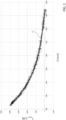
- Figure 3 shows an example of the temperature signal T object as the distance of the user 11 from the measuring device 10 varies.
- the curve shown in Figure 3 is better described hereinbelow.
- the TMOS sensor may operate with an "output data rate" (ODR) equal to about 8 Hz.
- ODR output data rate
- the distance sensor 24 and the IR sensor 26 extend at the main surface 12 in such a way as to face the user 11 when the latter is in the use position of the PC 10.
- the distance sensor 24 and the IR sensor 26 are lateral to each other with respect to the main surface 12.
- the fields of view 24' and 26' of the distance sensor 24 and the IR sensor 26 are superimposed on each other at the use position of the PC 10.
- the fields of view 24' and 26' have a superimposition region 28 which comprises the use position of the PC 10, so that the user 11 is detected by both the distance sensor 24 and the IR sensor 26 when he/she is in the use position of the PC 10.
- the field of view 24' of the distance sensor 24 has a detection angle (or opening angle) ⁇ 1 equal to about 25° and the field of view 26' of the IR sensor 26 has a respective detection angle (or opening angle) ⁇ 2 equal to about 80°.
- the distance sensor 24 and the IR sensor 26 have a mutual distance (not shown) which is substantially negligible (e.g., which may be lower than a few cm), as a result the superimposition region 28 is almost equal in extension to the smaller of the fields of view 24' and 26' (here the field of view 24').
- the distance between the user 11 and the distance sensor 24 and the distance between the user 11 and the IR sensor 26 are substantially equal to each other and that they define the distance D between the user 11 and the PC 10. It has been verified that this is especially true when a high mutual superimposition of the fields of view 24' and 26' is present, as previously described.
- an exact value of the distance D between the user 11 and the PC 10 may be calculated starting from the distance between the user 11 and the distance sensor 24 and/or from the distance between the user 11 and the IR sensor 26, on the basis of the actual arrangement of the distance sensor 24 and/or the IR sensor 26 in the PC 10 and of known trigonometric techniques.
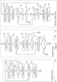
- control unit 22 implements a measuring method 50 now described with reference to Figure 4 .
- control unit 22 determines the distance D between the user 11 and the measuring device 20 on the basis of the temperature signal T object acquired by the IR sensor 26.
- the measuring method 50 identifies a calibration mode 50a, a calibrated mode 50b, and a calibration update mode 50c of the measuring device 20.
- the measuring device 20 When the measuring device 20 is turned on or is provided with a measurement start signal, the measuring device 20 is initially operated in the calibration mode 50a in order to be calibrated. As better described below, during calibration the distance signal S d and the temperature signal T object are acquired and, on the basis of these signals, a calibration curve (in particular, an example is shown in Figure 3 with the reference C c ) is generated wherein the values of the temperature signal T object are associated with respective values of the distance D in such a way that the distance D may be determined on the basis of the temperature signal T object . Consequently, in this mode both the distance sensor 24 and the IR sensor 26 are always active.
- a calibration curve in particular, an example is shown in Figure 3 with the reference C c
- the measuring device 20 is operated in the calibrated mode 50b.
- the temperature signal T object is acquired, and on the basis of this signal and the calibration curve C c , the distance D is determined.
- a calibration update condition is confirmed which implies the need for an update of the calibration previously performed in the calibration mode 50a.
- both the temperature signal T object and, periodically, the distance signal S d are acquired and, on the basis of these signals, the calibration update condition is verified. Consequently, in this mode the IR sensor 26 is always active and the distance sensor 24 is only periodically active.
- the measuring device 20 is operated in the calibration update mode 50c.
- the calibration update mode 50c the measuring device 20 is calibrated again to obtain an updated calibration curve C c , on the basis of the newly acquired values of the distance signal S d and the temperature signal T object .
- the calibration of the measuring device 20 may be updated following variations in the environmental conditions of the place where the PC 10 is present (e.g., turning on an air conditioner or a heating system which modifies the temperature of the air surrounding the PC 10), which impact the measurements of the IR sensor 26 and/or the distance sensor 24, making them inaccurate and therefore requiring new calibration. Consequently, in this mode both the distance sensor 24 and the IR sensor 26 are always active.
- the measuring device 20 is operated again in the calibrated mode 50b, on the basis of the updated calibration curve C c .
- FIG. 4 shows in detail an embodiment of the measuring method 50.
- the control unit 22 acquires the distance signal S d through the distance sensor 24 and the temperature signal T object through the IR sensor 26.
- respective values of the distance signal S d and of the temperature signal T object also indicated hereinafter respectively as S d,i and T object.i where i is the index corresponding to the time instant considered.
- this pair of values correspond to measurements performed simultaneously.
- These values S d,i and T object.i are respectively indicative of the distance D of the user 11 from the measuring device 20 measured by the distance sensor 24, and of the IR radiation emitted by the user 11 and detected by the IR sensor 26.
- these values S d,i and T object,i may be electrical quantities (e.g., electric voltage or electric current values) indicative of the distance D measured by the distance sensor 24 and of the IR radiation emitted by the user 11 and detected by the IR sensor 26, or they may correspond respectively to the information of the distance D measured by the distance sensor 24 and of the IR radiation emitted by the user 11 and detected by the IR sensor 26.
- electrical quantities e.g., electric voltage or electric current values
- the control unit 22 calculates a minimum distance signal difference S d,mindist on the basis of the measured value S d,i of the distance signal S d and stored values S buffer,k of the distance signal S d which have been stored, in particular in a buffer (e.g., present in the data storage unit of the control unit 22).
- the buffer is configured to store a number K (e.g., about 20) of pairs of values S d,i and T object, i , i.e. K values T object,i and K corresponding values S d,i each indicative of a respective value D i of distance D of the user 11 from the measuring device 20.
- K e.g., about 20
- the minimum distance signal difference S d,mindist is defined as the minimum difference between the differences (in absolute value) calculated between the measured value S d,i acquired at the instant i considered and each of the stored values S buffer,k present in the buffer.
- the minimum distance signal difference S d,mindist is a distance value that may be obtained by converting into distance the minimum difference value (e.g., electrical quantity) calculated starting from the stored values S buffer,k and the measured value S d,i (e.g., electrical quantities) or which may be obtained by converting into distances the stored values S buffer,k and the measured value S d,i (e.g., electrical quantities) and then calculating the minimum difference thereof.
- the minimum distance signal difference S d,mindist is indicative of the proximity of the measured value S d,i to the stored values S buffer,k .
- the control unit 22 verifies whether the minimum distance signal difference S d,mindist calculated for the value S d,i is greater than a minimum threshold difference S d,th (for example, a distance equal to about 30 mm) .
- step S16 of the calibration mode 50a (consecutive to step S14) wherein the buffer is updated by storing the new pair of measured values S d,i and T object,i therein, since this pair of values is sufficiently distant and therefore different from the pairs of values already stored in the buffer, i.e. it refers to a value D i of distance D which is sufficiently distant from the values of the distance D having the respective pairs of values already stored in the buffer corresponding thereto.
- the first pair of measured values S d,i and T object.i is stored in the buffer.
- the new pairs of measured values S d,i and T object,i are stored in the buffer only if they meet the condition of step S14.
- step S18 of the calibration mode 50a the control unit 22 verifies whether the buffer is complete, i.e. whether it is full and therefore whether K pairs of values S d,i and T object,i are stored therein.
- the measuring method 50 returns to step S10 so as to be able to continue to fill the buffer.
- step S20 of the calibration mode 50a (consecutive to step S18) wherein the calibration curve C c previously described and shown in Figure 3 is calculated.
- each of these pairs of values D buffer,k and T buffer,k may be graphically represented as a respective point in a two-dimensional plot which has the distance D measured through the distance sensor 24 on the abscissa axis and the temperature signal T object measured by the IR sensor 26 on the ordinate axis.
- the control unit 22 determines the calibration curve C c by interpolating the points of this set, i.e. by interpolating the pairs of values D buffer,k and T buffer,k .
- This allows a function, in particular a biunivocal function, between the distance D measured through the distance sensor 24 and the temperature signal T object measured through the IR sensor 26 to be obtained. Consequently, the calibration curve C c associates each value of the distance D measured through the distance sensor 24 with a respective value of the temperature signal T object measured by the IR sensor 26, and vice versa.
- the interpolating function may be an exponential function, a first-degree polynomial function, a second-degree polynomial function or a third-degree polynomial function. Nonetheless, other known interpolating functions may be used. In particular, it has been verified that the second- and third-degree polynomial functions are those that allow achieving the best interpolation accuracy among the interpolating functions mentioned herein.
- the interpolating function may be chosen in the design step of the measuring device 20 and therefore may be predefined and fixed, or it may be chosen in real time and adaptively from among multiple predefined interpolating functions depending on the set of the pairs of values D buffer,k and T buffer,k .
- the interpolating functions previously described the one that best interpolates the values D buffer,k and T buffer,k of the stored set may be selected.
- the selection of the curve with optimized interpolation occurs in a per se known manner.
- the calibration mode 50a therefore ends with the calculation of the calibration curve C c at step S20.
- the measuring device 20 is calibrated, since the means are available to accurately measure the distance D starting from the temperature signal T object acquired by the IR sensor 26.
- step S20 the measuring method 50 proceeds with the calibrated mode 50b of the measuring device 20.
- the control unit 22 acquires a new value T object,i of the temperature signal T object through the IR sensor 26.
- This new value T object,i is correlated, as previously described, to the new value D i of distance D of the user 11 from the measuring device 20. Consequently, at step S22 the distance sensor 24 is inactive, i.e. it is not performing any measurement.
- the control unit 22 determines the new value D i of distance D on the basis of the new value T object,i of the temperature signal T object and the calibration curve C c .
- the new value D i is the value of distance D which, in the calibration curve C c , corresponds to the new measured value T object,i of the temperature signal T object .
- the measuring method 50 proceeds to a step S26 of the calibrated mode 50b (consecutive to step S24), wherein the control unit 22 verifies whether performing a calibration control (also called periodic calibration control) is needed to verify the reliability of the calibration curve C c previously calculated.
- a calibration control also called periodic calibration control
- the measuring method 50 proceeds to a step S34 of the calibrated mode 50b, better described hereinbelow.
- the measuring method 50 proceeds to a step S28 of the calibrated mode 50b (consecutive to step S26) wherein the control unit 22 acquires a new value S d,i of the distance signal S d through the distance sensor 24. Consequently, at step S28 the distance sensor 24 is active.
- the control unit 22 calculates a distance signal error D err .
- an estimated value D object,i of the distance D is determined as a function of the calibration curve C c and the measured value T object,i of the temperature signal T object acquired at step S22 (similarly to what is done at step S24). Furthermore, a value D d,i of the distance D is determined as a function of the value S d,i of the distance signal S d acquired at step S28 (similarly to what is done at step S10).
- the distance sensor 24 Since the distance sensor 24 has a measurement accuracy of the distance D greater than the IR sensor 26, it is assumed here that the value D d,i coincides with the actual distance D at the instant of the iteration considered, i.e. that it is one correct and realistic measurement thereof. Consequently, the correct or anomalous operating state of the IR sensor 26 is determined as regards the measurement carried out by the distance sensor 24, in such a way that the anomalous operation corresponds to a substantial relative offset of the distance measurements obtained from the IR sensor 26 (through the application of the calibration curve C c ) and from the distance sensor 24.
- the distance signal error D err is therefore defined as the difference, in absolute value, between the estimated value (or estimated distance value) D object,i obtained through the IR sensor 26 and the value (or measured distance value) D d,i obtained through the distance sensor 24.
- the control unit 22 verifies a first unreliability condition of the calibration curve C c used to calculate the value D object,i .
- the first unreliability condition corresponds to an anomaly in the calibration detected through a verification on the data of the distance sensor 24 (for simplicity it is therefore also called anomaly of the distance sensor 24).
- the calibration curve C c used to calculate the value D object,i is potentially unreliable and therefore going to the calibration update mode 50c is needed for further checks and, if after these checks the need thereof is detected, for updating the calibration curve C c .
- the measuring method 50 proceeds to a step S50 of the calibration update mode 50c, better discussed hereinbelow.
- the measuring method 50 proceeds to a step S34 of the calibrated mode 50b (consecutive both to step S32 through its output "N” and to step S26 through its output "N").
- control unit 22 calculates a minimum temperature signal difference T object,mindist .
- the minimum temperature signal difference T object,mindist is calculated on the basis of the measured value T object,i of the temperature signal T object , previously acquired at the latest execution of step S22, and the stored values T buffer,k of the temperature signal T object which have been stored in the buffer.
- the minimum temperature signal difference T object,mindist is defined as the minimum difference between the differences (in absolute value) calculated between the measured value T object,i acquired at step S22 and each of the stored values T buffer,k present in the buffer.
- the control unit 22 verifies a second unreliability condition of the calibration curve C c used to calculate the value D object,i-
- the second unreliability condition corresponds to an anomaly in the calibration detected through a verification on the data of the IR sensor 26 (for simplicity it is therefore also called anomaly of the IR sensor 26).
- step S36 it is checked whether the minimum temperature signal difference T object,mindist is greater than a minimum temperature signal threshold difference T object,th (e.g., equal to about 250 LSB).
- a minimum temperature signal threshold difference T object,th e.g., equal to about 250 LSB.
- the measuring method 50 returns to step S22.
- step S42 of the calibration update mode 50c the control unit 22 calculates again the distance signal error D err on the basis of the new values S d,i and T object,i acquired at step S38, similarly to what has been described in step S30.
- step S44 of the calibration update mode 50c the control unit 22 verifies again, in a manner similar to what has been described in step S32, the anomaly condition of the distance sensor 24 (i.e. the first unreliability condition) on the basis of the distance signal error D err calculated at step S42. In particular, it is checked whether the distance signal error D err is greater than the distance signal threshold error D err,th .
- step S44 If the anomaly condition of the distance sensor 24 of step S44 is not confirmed, the measuring method 50 proceeds to a step S46 of the calibration update mode 50c (consecutive to step S44).
- the count index n is initialized to an initial value (e.g., 0) every time that the method goes from calibrated mode 50b to calibration update mode 50c.
- the count index n is updated during the calibration update mode 50c and may vary between a predefined minimum value (e.g., the initial value) and a predefined maximum value (or predefined number) N (e.g., 15).
- step S48 of the calibration update mode 50c the control unit 22 verifies whether a first update condition (or minimum update condition) is confirmed.
- the first update condition is confirmed if the count index n assumes the predefined minimum value (e.g., 0).
- the measuring method 50 returns to step S22 of the calibrated mode 50b since the detected anomaly of the distance sensor 24 did not last sufficiently to be indicative of a real lack of reliability of the calibration curve C c such as to require a new calibration (i.e. it has not been detected for N time instants).
- step S50 of the calibration update mode 50c (which is therefore consecutive both to step S44 through the output "S” and to step S32 through the output "S").
- control unit 22 updates the value of the count index n by increasing its value by one unit.
- step S50 since in case of confirmation of the anomaly condition of the distance sensor 24 at step S32 the method goes directly to step S50 (i.e. this step is the first that is performed when entering the calibration update mode 50c), the count index n is increased by one unit immediately after being initialized to the initial value. This avoids the possibility that, at step S46, the count index n is updated to a value lower than the initial value and therefore that count errors arise.
- step S52 of the calibration update mode 50c the control unit 22 verifies whether a second update condition (or maximum update condition) is confirmed.
- the second update condition is confirmed if the count index n assumes the predefined maximum value N (e.g., 15), i.e. if the anomaly lasted sufficiently to be indicative of a real lack of reliability of the calibration curve C c such as to require a new calibration (i.e. if it has been detected for N time instants).
- N the predefined maximum value
- the measuring method 50 returns to step S38.
- step S54 of the calibration update mode 50c (consecutive both to step S52 through the output "S” and to step S36 through the output "S").
- steps S38-S52 allow verifying whether the anomaly condition of the distance sensor 24 is confirmed for the predefined number N of time instants successive to each other (not necessarily consecutive to each other), therefore whether it lasted sufficiently to be indicative of a real lack of reliability of the calibration curve C c such as to require a new calibration.
- control unit 22 updates the buffer by storing therein a new pair of measured values S d,i and T object,i , as a replacement for the least recent pair of values (i.e. the oldest pair of values stored in the buffer).
- This new stored pair may be, in the case of an anomaly of the distance sensor 24, the last acquired pair and thus the pair of values S d,i and T object,i acquired at the latest execution of step S38.
- the new stored pair may be a new pair of values S d,i and T object,i which are acquired at this step.
- step S54 may comprise the acquisition of a new pair of values S d,i and T object,i , similarly to what has been previously described in steps S10 and S38, and the subsequent storage of this new pair of values in the buffer.
- step S56 of the calibration update mode 50c the control unit 22 updates the calibration curve C c on the basis of the buffer that has been updated at step S54. This occurs in a manner completely similar to what has been previously described in step S20.
- step S56 the measuring method 50 returns to step S22 as the measurement device 20 is calibrated again.
- the measuring device 20 may generate an output signal indicative of the value of the distance D.
- the output signal may be received by the PC 10 (or by external apparatuses operatively coupled to the measuring device 20) and may be used to control one or more functionalities of the PC 10 (or of the external apparatuses).
- the screen of the PC 10 may be automatically activated or deactivated as a function of the distance D measured between the user 11 and the PC 10.
- the output signal may be equal at any instant to the value D object,i calculated at the last step performed between steps S24 and S40 (therefore still using the IR sensor 26).
- the output signal may be equal to the value D object,i calculated at the last step performed between steps S24 and S40 when the distance sensor 24 is not active, and instead be equal to the value D d,i obtained at the last step performed between steps S30 and S42 when the distance sensor 24 is active: in this case, the output signal is generally equal to the measurement obtained using the IR sensor 26, except for when the measurement of the distance sensor 24 (which still has higher accuracy) is available.
- the measuring method 50 previously described may be implemented by the control unit 22 through a corresponding computer program product.
- the measuring device 20 and the measuring method 50 allow the distance D between the user 11 and the measuring device 20 to be measured with high accuracy and low electrical consumption.
- the measurement of the distance D is performed through the IR sensor 26 (which has low energy consumption), while the distance sensor 24 (with accurate measurement but high energy costs) is used only to calibrate the measurement of the IR sensor 26, to periodically verify whether there are anomalies in the measurements carried out and, if necessary, to recalibrate the measurement of the IR sensor 26.
- the distance D on the basis of the IR sensor 26 with measurement accuracy substantially comparable to the known case wherein the distance sensor 24 is used to perform this measurement may be measured.
- the electrical consumption is substantially reduced with respect to the known case wherein the distance sensor 24 is used (e.g., up to about 1000 times).
- the calibration update mode 50c ensures that, in case the value measured by the IR 26 sensor differs too much from the values previously stored in the buffer and used for the calculation of the calibration curve C c , the calibration is updated so as to bring the measurement of the measuring device 20 back to the desired levels of accuracy.
- the calibration update is performed if the anomaly is confirmed for N samples successive to each other, so that any isolated and transient anomalous results do not cause an unnecessary update of the calibration. This allows the energy consumption of the measuring device 20 to be further reduced.
- the measurement of the measuring device 20 allows the presence of the user 11 to be discriminated with respect to other bodies such as inanimate objects present in the fields of view 24' and 26'. In this manner, the measurement performed is selective to the user 11.
- steps S26-S56 may be omitted, to further reduce the energy consumption of the measuring device 20.
- the distance sensor 24 directly generates at output the information on the distance D, which is used for the calculation of the distance signal error D err in a manner similar to what has been previously described.
- the count index n may also be initialized to a value greater than the predefined minimum value (in particular, a value equal to one unit more than the predefined minimum value and therefore here exemplarily 1) and proceed directly to step S38.
- the predefined minimum value in particular, a value equal to one unit more than the predefined minimum value and therefore here exemplarily 1
- the method may proceed directly with the actions of step S38. This further simplifies the measuring method 50.
Landscapes
- Engineering & Computer Science (AREA)
- Physics & Mathematics (AREA)
- Radar, Positioning & Navigation (AREA)
- Remote Sensing (AREA)
- General Physics & Mathematics (AREA)
- Computer Networks & Wireless Communication (AREA)
- Electromagnetism (AREA)
- Spectroscopy & Molecular Physics (AREA)
- Acoustics & Sound (AREA)
- Optical Radar Systems And Details Thereof (AREA)
- Length Measuring Devices By Optical Means (AREA)
- Measurement Of Optical Distance (AREA)
Abstract
Description
- The present invention relates to a measuring device for measuring the distance of a user. Furthermore, it relates to an electronic apparatus comprising the measuring device, to a measuring method implemented by the measuring device and to a related computer program product.
- As known, energy consumption is a critical parameter to be assessed in the design of electronic equipment such as PCs, soundbars, smart appliances, IoT apparatuses, where it is required to minimize energy consumption yet without reducing the functionality that these electronic equipments may offer.
- Consequently, these electronic apparatuses are often automatically controlled as a function of some external factors, such as the presence of a user in proximity of the electronic apparatuses, in order to minimize energy consumptions. For example, the screen of a PC may be automatically activated or deactivated on the basis of whether or not the user is in proximity to the PC and in particular whether or not he/she is in a use position of the PC (i.e. within a predefined range of distance from the PC and in front of the screen). In this manner, the time in which the PC screen remains on without the PC being actually used is minimized and this allows the overall energy consumption of the PC to be reduced.
- Several known solutions are available to automatically control such electronic apparatuses on the basis of measurements of distance, or at least of presence/absence, of the user from the same electronic apparatuses.
- For example, using "Thermal MOS", TMOS, sensors is known to detect the presence of the user in a predetermined zone.
- The TMOS sensor is a known infrared sensor suitable for detecting the presence and movement of the user. In particular, the TMOS detects the intensity of the infrared, IR, radiation, emitted by a hot body (for example, the user of the electronic apparatus) present in a field of view (FoV) of the TMOS. The TMOS has low energy consumption (e.g., about 20 µA) and a wide field of view (e.g., with a detection angle of about 80°) but cannot generally be used for measuring the distance of the person from the sensor since the intensity of the IR radiation does not solely depend on the distance of the user from the sensor, but rather also depends on external factors such as environmental temperature and humidity and is subject to drift over time. In general, this is due to the fact that this IR sensor is not capable of measuring the absolute distance of the user from the TMOS sensor but may rather detect the intensity of the IR radiation generated by the bodies emitting IR radiation (which is indicative of their temperature and is correlated to their distance from the TMOS sensor).
- For this reason, the TMOS is not used in applications that require accurate measurements of the distance of the user but is rather used to detect the presence or absence of the user within a predefined distance range.
- A sensor that is instead commonly used to measure the distance of objects or people is a Time of Flight (ToF) sensor. The ToF sensor may be based on different technologies, such as ultrasonic technology or optical technology.
- In the exemplary case of the ultrasonic ToF sensor, it comprises an emitter configured to emit ultrasounds towards the body to be detected, and a receiver configured to receive the ultrasounds which, after being emitted by the emitter, have been reflected by the body to be detected. The ultrasonic ToF sensor measures the time of flight of the ultrasounds (i.e. the time interval elapsing between the emission of the ultrasounds by the emitter and their reception by the receiver) and calculates the distance of the body with respect to the ToF sensor on the basis of the time of flight measured. The operating principle of the optical ToF sensor is completely similar to that of the ultrasonic ToF sensor but, instead of being based on the emission and reception of ultrasonic waves, it is based on the emission and reception of light radiation (e.g., the emitter may include a "Single Photon Avalanche Diode", SPAD).
- Consequently, the ToF sensor allows the distances of bodies (for example a person) present in the field of view of the ToF sensor to be measured. The ToF sensor has a high precision in measuring the distance of the user from the sensor but also has high energy consumption (e.g., about 20 mA) and a very narrow field of view (e.g., with a detection angle of about 25°).
- For these reasons, the ToF sensor is generally used for measuring distance, although the previously listed issues do not make its use optimal in several applications (e.g., low-power applications).
- The need is therefore felt to detect the distance of the user from the electronic equipment (e.g., a PC) with high precision and without high energy consumptions, in order to automatically control the functionalities of the electronic equipment (for example for automatically turning the PC screen on and off on the basis of the user's presence) .
- Document
EP 3 433 571 A1 relates to a distance determination that can utilize an electronic device including an infrared sensor to detect a thermal signature of a subject at a first location and a thermal signature of the subject at a second location, a distance sensor to determine a distance of the subject at the first location from the electronic device, and a controller to determine a physical size based on the determined distance and the thermal signature of the subject at the first location, and determine a distance of the subject at a second location based on the physical size and a thermal signature of the subject at the second location. - Document
EP 2 959 459 A1 relates to three-dimensional imaging and, in particular, to a system and method for three-dimensional imaging utilising thermal infrared image data. - Document
JP 2014 149761 A - The aim of the present invention is to provide a measuring device, an electronic apparatus, a measuring method and a computer program product, which overcome the drawbacks of the prior art.
- According to the present invention, a measuring device, an electronic apparatus, a measuring method and a computer program product are provided, as defined in the annexed claims.
- For a better understanding of the present invention, a preferred embodiment is now described, purely by way of non-limiting example, with reference to the attached drawings, wherein:
-
Figure 1 is a schematic perspective view of an electronic apparatus which comprises a measuring device, according to one embodiment; -
Figure 2 is a schematic view showing the electronic apparatus ofFigure 1 and further details regarding the measuring device, according to one embodiment; -
Figure 3 is a plot showing a calibration curve obtained through the measuring device, according to one embodiment; and -
Figure 4 is a block diagram showing a measuring method performed through the measuring device, according to one embodiment. - In particular, the Figures are shown with reference to a triaxial Cartesian system defined by an X axis, a Y axis and a Z axis, orthogonal to each other.
- In the following description, elements common to the different embodiments have been indicated with the same reference numbers.
-
Figure 1 shows anelectronic apparatus 10 usable by a user (shown inFigure 2 with the reference 11). -
Figure 1 shows the illustrative and non-limiting case wherein theelectronic apparatus 10 is a PC (therefore hereinafter also indicated with the reference 10). In the following, this exemplary case is considered, nonetheless other types ofelectronic apparatuses 10 may be similarly considered. For illustrative and non-limiting purposes, theelectronic apparatus 10 may also be a soundbar, a smart appliance, an IoT apparatus, a tablet, etc. - The PC 10 comprises a
measuring device 20 better described hereinbelow and configured to measure the distance of theuser 11 from the PC 10. - In particular, the
measuring device 20 extends at amain surface 12 of the PC 10 which theuser 11 faces when the latter is present and is in a use position (or interest position, predefined position) of the PC 10. - In detail, the use position is the position, or more generally the set of positions, in which the
user 11 may use the PC 10. For example, the use position is identified by the fact that theuser 11 is placed in front of the PC 10 and is distant from PC 10 by a distance lower than a threshold distance. In greater detail, the distance (shown inFigure 2 with the reference D) between theuser 11 and themeasuring device 20 may be considered as the distance between theuser 11 and thePC 10 and the threshold distance may be, for illustrative and non-limiting purposes, equal to about 80 cm. - For example, the PC 10 comprises a
screen 14 which defines part of themain surface 12 and, as shown inFigure 1 , themeasuring device 20 may extend on thescreen 14, for example laterally to avideo camera 16 of the PC 10. - In this manner, when the
user 11 is in the use position of the PC 10, theuser 11 faces themeasuring device 20 which may therefore measure the distance D present between it and theuser 11. - With reference to
Figure 2 , themeasuring device 20 is now described in more detail. - The
measuring device 20 comprises acontrol unit 22, adistance sensor 24 and an infrared, IR,radiation sensor 26. Hereinafter, theIR radiation sensor 26 is also more simply calledIR sensor 26. - According to an exemplary embodiment, the control unit 22 (such as a microprocessor, a microcontroller or a dedicated calculation unit) is an electronic control unit which may comprise, coupled to each other, a data storage unit (not shown, such as a memory, e.g. a non-volatile memory) for storing acquired data and a processing unit (not shown) for processing acquired data. In a manner not shown and known per se, the control unit may also comprise one or more of the following components: an electrical energy storage module (e.g., a battery), a power management module for managing the electrical energy, a digital front-end interface module with the
distance sensor 24 and theIR sensor 26, a communication module (e.g., a radio communication module based on Bluetooth technology). - The
distance sensor 24 and theIR sensor 26 are coupled (e.g., electrically coupled) to thecontrol unit 22. For example, thedistance sensor 24 and theIR sensor 26 are coupled to thecontrol unit 22 through the digital front-end interface module of thecontrol unit 22, of a per se known type. - For example, the
distance sensor 24 and theIR sensor 26 may optionally be of micro electro-mechanical systems, MEMS, type. In other words, they may be made using known micromanufacturing techniques for processing semiconductor materials, such as for example silicon. Nonetheless, other technologies may be similarly considered. - The
distance sensor 24 is a distance sensor of known type, configured to measure the distance D between theuser 11 and themeasuring device 20 when theuser 11 is in a field of view 24' of thedistance sensor 24. - In particular, the
distance sensor 24 is a time of flight (ToF) sensor, for example an ultrasonic or optical ToF sensor. - Hereinafter, the case wherein the
distance sensor 24 is an optical ToF sensor is exemplarily considered, however other types of ToF sensors (e.g., ultrasonic sensors) or distance sensors may be considered. - In use, the
distance sensor 24 generates a distance signal Sd which is received by thecontrol unit 22 and is indicative, when theuser 11 is in the field of view 24', of the distance D of theuser 11 from the distance sensor 24 (i.e. from the measuring device 10). - The
IR sensor 26 is an IR radiation sensor configured to detect the IR radiation emitted by an emitting body (i.e. a hot body and in particular the user 11) when the latter is in a field of view 26' of theIR sensor 26. - In particular, the
IR sensor 26 is a "Thermal MOS", TMOS, sensor, of known type and which operates as a detector of the IR radiation emitted by theuser 11. - In particular, the TMOS is a field effect transistor device of known type and typically used in sensor applications to determine the amount of radiation (in detail IR radiation) emitted by an emitting body, here the
user 11. The emitting body is any hot body that emits IR radiation, such as a person or an animal. The radiation, emitted by the emitting body and received by the TMOS, causes the generation of charge carriers at the conductive channel of the TMOS and, therefore, a corresponding variation in the output current of the TMOS; the latter may be related to the extent of the radiation emitted by the object under examination, in such a way as to have a measure of the radiation emitted by the emitting body. - In general, the TMOS allows the presence or absence of the
user 11 to be detected in its field of view 26'. - According to an embodiment exemplarily considered hereinbelow, the TMOS present in the measuring
device 10 is the Infrared Temperature Sensor TMOS marketed by STMicroelectronics with the reference code STHS34PF80 (further details may be found at the address https://www.st.com/en/mems-and-sensors/infrared-ir-sensors.html) . - In particular, the TMOS sensor (in detail STMicroelectronics' STHS34PF80) is capable of generating one temperature signal correlated to the presence or absence of the
user 11 in the field of view 26'. - The temperature signal is a signal indicative of the temperature of the entities (living beings such as people or inanimate but hot objects such as heating apparatuses) present in the field of view 26' of the
IR sensor 26. - Consequently, the temperature signal is determined as a function of both the IR radiation emitted by the
user 11 present in the field of view 26' of the TMOS sensor, and the IR radiation which may normally be present in the environment wherein the TMOS sensor is placed even in the absence of living beings. In other words, the temperature signal has a baseline which depends on the amount of environmental IR radiation that the TMOS sensor measures in the absence of theuser 11 in the field of view 26' (e.g., due to electromagnetic noise of the environment wherein the TMOS sensor is present, at the temperature of the air surrounding the TMOS sensor, etc.), and may vary with respect to this baseline when the TMOS sensor detects the IR radiation emitted by theuser 11, which adds to the environmental IR radiation already present. Consequently, peaks of the temperature signal of the TMOS sensor with respect to its baseline are indicative of the presence of theuser 11 in the field of view 26' of theIR sensor 26. - In particular, the TMOS sensor may be of temperature-compensated type, in a per se known manner.
- In the embodiment here considered wherein the TMOS sensor is the STMicroelectronics' STHS34PF80, the temperature signal corresponds to the signal Tobject (or even Tobj) indicated in the datasheet of the TMOS sensor. For this reason, hereinafter the temperature signal is indicated with the reference Tobject.
- Therefore, in use, the
IR sensor 26 generates the temperature signal Tobject which is received by thecontrol unit 22 and is indicative, when theuser 11 is in the field of view 26', of the intensity of the IR radiation emitted by theuser 11 and detected by theIR sensor 26. Considering that the IR radiation detected by theIR sensor 26 is directly proportional to the intensity of the IR radiation emitted by the emitting body but is also inversely proportional to the distance between theIR sensor 26 and the emitting body, the temperature signal Tobject is correlated to the distance D of theuser 11 from the IR sensor 26 (i.e. from the measuring device 10). Consequently, and as better described hereinbelow, the distance D may be measured starting from the temperature signal Tobject. - In particular,
Figure 3 shows an example of the temperature signal Tobject as the distance of theuser 11 from the measuringdevice 10 varies. The curve shown inFigure 3 is better described hereinbelow. - For example, in the present application the TMOS sensor may operate with an "output data rate" (ODR) equal to about 8 Hz.
- As shown in
Figure 2 , thedistance sensor 24 and theIR sensor 26 extend at themain surface 12 in such a way as to face theuser 11 when the latter is in the use position of thePC 10. - For example, the
distance sensor 24 and theIR sensor 26 are lateral to each other with respect to themain surface 12. - The fields of view 24' and 26' of the
distance sensor 24 and theIR sensor 26 are superimposed on each other at the use position of thePC 10. In other words, the fields of view 24' and 26' have asuperimposition region 28 which comprises the use position of thePC 10, so that theuser 11 is detected by both thedistance sensor 24 and theIR sensor 26 when he/she is in the use position of thePC 10. - For example, the field of view 24' of the
distance sensor 24 has a detection angle (or opening angle) α1 equal to about 25° and the field of view 26' of theIR sensor 26 has a respective detection angle (or opening angle) α2 equal to about 80°. - Considering that the
distance sensor 24 and theIR sensor 26 have a mutual distance (not shown) which is substantially negligible (e.g., which may be lower than a few cm), as a result thesuperimposition region 28 is almost equal in extension to the smaller of the fields of view 24' and 26' (here the field of view 24'). For this same reason, it may be considered that the distance between theuser 11 and thedistance sensor 24 and the distance between theuser 11 and theIR sensor 26 are substantially equal to each other and that they define the distance D between theuser 11 and thePC 10. It has been verified that this is especially true when a high mutual superimposition of the fields of view 24' and 26' is present, as previously described. However, it remains apparent that an exact value of the distance D between theuser 11 and thePC 10 may be calculated starting from the distance between theuser 11 and thedistance sensor 24 and/or from the distance between theuser 11 and theIR sensor 26, on the basis of the actual arrangement of thedistance sensor 24 and/or theIR sensor 26 in thePC 10 and of known trigonometric techniques. - In use, the
control unit 22 implements a measuringmethod 50 now described with reference toFigure 4 . - In particular, in use, the
control unit 22 determines the distance D between theuser 11 and the measuringdevice 20 on the basis of the temperature signal Tobject acquired by theIR sensor 26. - The measuring
method 50 identifies acalibration mode 50a, a calibratedmode 50b, and acalibration update mode 50c of the measuringdevice 20. - When the measuring
device 20 is turned on or is provided with a measurement start signal, the measuringdevice 20 is initially operated in thecalibration mode 50a in order to be calibrated. As better described below, during calibration the distance signal Sd and the temperature signal Tobject are acquired and, on the basis of these signals, a calibration curve (in particular, an example is shown inFigure 3 with the reference Cc) is generated wherein the values of the temperature signal Tobject are associated with respective values of the distance D in such a way that the distance D may be determined on the basis of the temperature signal Tobject. Consequently, in this mode both thedistance sensor 24 and theIR sensor 26 are always active. - After the
calibration mode 50a, the measuringdevice 20 is operated in the calibratedmode 50b. In the calibratedmode 50b, the temperature signal Tobject is acquired, and on the basis of this signal and the calibration curve Cc, the distance D is determined. Furthermore, in this mode it is periodically verified whether a calibration update condition is confirmed which implies the need for an update of the calibration previously performed in thecalibration mode 50a. In particular and as better described hereinbelow, both the temperature signal Tobject and, periodically, the distance signal Sd are acquired and, on the basis of these signals, the calibration update condition is verified. Consequently, in this mode theIR sensor 26 is always active and thedistance sensor 24 is only periodically active. - When the calibration update condition is confirmed, the measuring
device 20 is operated in thecalibration update mode 50c. In thecalibration update mode 50c, the measuringdevice 20 is calibrated again to obtain an updated calibration curve Cc, on the basis of the newly acquired values of the distance signal Sd and the temperature signal Tobject. In particular, the calibration of the measuringdevice 20 may be updated following variations in the environmental conditions of the place where thePC 10 is present (e.g., turning on an air conditioner or a heating system which modifies the temperature of the air surrounding the PC 10), which impact the measurements of theIR sensor 26 and/or thedistance sensor 24, making them inaccurate and therefore requiring new calibration. Consequently, in this mode both thedistance sensor 24 and theIR sensor 26 are always active. - Following the update of the calibration curve Cc, the measuring
device 20 is operated again in the calibratedmode 50b, on the basis of the updated calibration curve Cc. -
Figure 4 shows in detail an embodiment of the measuringmethod 50. - At a step S10 of the
calibration mode 50a, thecontrol unit 22 acquires the distance signal Sd through thedistance sensor 24 and the temperature signal Tobject through theIR sensor 26. In particular, at the time instant considered there are acquired respective values of the distance signal Sd and of the temperature signal Tobject, also indicated hereinafter respectively as Sd,i and Tobject.i where i is the index corresponding to the time instant considered. In other words, this pair of values correspond to measurements performed simultaneously. These values Sd,i and Tobject.i are respectively indicative of the distance D of theuser 11 from the measuringdevice 20 measured by thedistance sensor 24, and of the IR radiation emitted by theuser 11 and detected by theIR sensor 26. For example, these values Sd,i and Tobject,i may be electrical quantities (e.g., electric voltage or electric current values) indicative of the distance D measured by thedistance sensor 24 and of the IR radiation emitted by theuser 11 and detected by theIR sensor 26, or they may correspond respectively to the information of the distance D measured by thedistance sensor 24 and of the IR radiation emitted by theuser 11 and detected by theIR sensor 26. - At a step S12 of the
calibration mode 50a (consecutive to step S10), thecontrol unit 22 calculates a minimum distance signal difference Sd,mindist on the basis of the measured value Sd,i of the distance signal Sd and stored values Sbuffer,k of the distance signal Sd which have been stored, in particular in a buffer (e.g., present in the data storage unit of the control unit 22). - As better described hereinbelow, the buffer is configured to store a number K (e.g., about 20) of pairs of values Sd,i and Tobject, i, i.e. K values Tobject,i and K corresponding values Sd,i each indicative of a respective value Di of distance D of the
user 11 from the measuringdevice 20. - The minimum distance signal difference Sd,mindist is defined as the minimum difference between the differences (in absolute value) calculated between the measured value Sd,i acquired at the instant i considered and each of the stored values Sbuffer,k present in the buffer. In particular, the minimum distance signal difference Sd,mindist is a distance value that may be obtained by converting into distance the minimum difference value (e.g., electrical quantity) calculated starting from the stored values Sbuffer,k and the measured value Sd,i (e.g., electrical quantities) or which may be obtained by converting into distances the stored values Sbuffer,k and the measured value Sd,i (e.g., electrical quantities) and then calculating the minimum difference thereof. In other words, the minimum distance signal difference Sd,mindist is calculated according to the following mathematical expression:

- Consequently, the minimum distance signal difference Sd,mindist is indicative of the proximity of the measured value Sd,i to the stored values Sbuffer,k.
- At a step S14 of the
calibration mode 50a (consecutive to step S12), thecontrol unit 22 verifies whether the minimum distance signal difference Sd,mindist calculated for the value Sd,i is greater than a minimum threshold difference Sd,th (for example, a distance equal to about 30 mm) . - If the minimum distance signal difference Sd,mindist is not greater than the minimum threshold difference Sd,th, the measuring
method 50 returns to step S10 and the pair of values Sd,i and Tobject.i is not stored in the buffer because it is too close and similar to a pair of values already stored in the buffer, i.e. it refers to a value Di of distance D which is too close to the values of the distance D having the respective pairs of values already stored in the buffer corresponding thereto. - If the minimum distance signal difference Sd,mindist is greater than the minimum threshold difference Sd,th, the method proceeds to a step S16 of the
calibration mode 50a (consecutive to step S14) wherein the buffer is updated by storing the new pair of measured values Sd,i and Tobject,i therein, since this pair of values is sufficiently distant and therefore different from the pairs of values already stored in the buffer, i.e. it refers to a value Di of distance D which is sufficiently distant from the values of the distance D having the respective pairs of values already stored in the buffer corresponding thereto. - At the first iteration of the measuring
method 50 wherein the buffer is empty, the first pair of measured values Sd,i and Tobject.i is stored in the buffer. At subsequent iterations the new pairs of measured values Sd,i and Tobject,i are stored in the buffer only if they meet the condition of step S14. - At a step S18 of the
calibration mode 50a (consecutive to step S16), thecontrol unit 22 verifies whether the buffer is complete, i.e. whether it is full and therefore whether K pairs of values Sd,i and Tobject,i are stored therein. - If the buffer is not complete, the measuring
method 50 returns to step S10 so as to be able to continue to fill the buffer. - If the buffer is complete, the method proceeds to a step S20 of the
calibration mode 50a (consecutive to step S18) wherein the calibration curve Cc previously described and shown inFigure 3 is calculated. - In particular, starting from the values of the distance signal Sd which have been stored in the buffer (also indicated hereinafter with the reference Sbuffer,k with k=1,...,K) respective values Dbuffer,k of the distance D are determined, in a per se known manner (e.g., through known transfer functions). Alternatively, in case the values Sbuffer,k of the distance signal Sd which have been stored in the buffer are already distance information, this intermediate step may be omitted since the distance information is already available (in this case, Sbuffer,k=Dbuffer,k).
- Thanks to the data stored in the buffer, each value Dbuffer,k calculated starting from the respective value Sbuffer,k is coupled to a respective value of the temperature signal Tobject stored in the buffer (also indicated hereinafter with the reference Tbuffer,k with k=1,...,K). In this manner, a set of pairs of values Dbuffer,k and Tbuffer,k associated with each other is defined.
- As shown in
Figure 3 , each of these pairs of values Dbuffer,k and Tbuffer,k may be graphically represented as a respective point in a two-dimensional plot which has the distance D measured through thedistance sensor 24 on the abscissa axis and the temperature signal Tobject measured by theIR sensor 26 on the ordinate axis. - The
control unit 22 then determines the calibration curve Cc by interpolating the points of this set, i.e. by interpolating the pairs of values Dbuffer,k and Tbuffer,k. This allows a function, in particular a biunivocal function, between the distance D measured through thedistance sensor 24 and the temperature signal Tobject measured through theIR sensor 26 to be obtained. Consequently, the calibration curve Cc associates each value of the distance D measured through thedistance sensor 24 with a respective value of the temperature signal Tobject measured by theIR sensor 26, and vice versa. - This interpolation may be carried out on the basis of several known mathematical functions. For example, the interpolating function may be an exponential function, a first-degree polynomial function, a second-degree polynomial function or a third-degree polynomial function. Nonetheless, other known interpolating functions may be used. In particular, it has been verified that the second- and third-degree polynomial functions are those that allow achieving the best interpolation accuracy among the interpolating functions mentioned herein.
- The interpolating function may be chosen in the design step of the measuring
device 20 and therefore may be predefined and fixed, or it may be chosen in real time and adaptively from among multiple predefined interpolating functions depending on the set of the pairs of values Dbuffer,k and Tbuffer,k. In this second case, among the interpolating functions previously described the one that best interpolates the values Dbuffer,k and Tbuffer,k of the stored set may be selected. The selection of the curve with optimized interpolation occurs in a per se known manner. - The
calibration mode 50a therefore ends with the calculation of the calibration curve Cc at step S20. At this point, in fact, the measuringdevice 20 is calibrated, since the means are available to accurately measure the distance D starting from the temperature signal Tobject acquired by theIR sensor 26. - After step S20, the measuring
method 50 proceeds with the calibratedmode 50b of the measuringdevice 20. - In particular, at a step S22 of the calibrated
mode 50b (consecutive to step S20) thecontrol unit 22 acquires a new value Tobject,i of the temperature signal Tobject through theIR sensor 26. This new value Tobject,i is correlated, as previously described, to the new value Di of distance D of theuser 11 from the measuringdevice 20. Consequently, at step S22 thedistance sensor 24 is inactive, i.e. it is not performing any measurement. - At a step S24 of the calibrated
mode 50b (consecutive to step S22), thecontrol unit 22 determines the new value Di of distance D on the basis of the new value Tobject,i of the temperature signal Tobject and the calibration curve Cc. In particular, the new value Di is the value of distance D which, in the calibration curve Cc, corresponds to the new measured value Tobject,i of the temperature signal Tobject. - After determining the new distance D on the basis of the measurement carried out by the
IR sensor 26, the measuringmethod 50 proceeds to a step S26 of the calibratedmode 50b (consecutive to step S24), wherein thecontrol unit 22 verifies whether performing a calibration control (also called periodic calibration control) is needed to verify the reliability of the calibration curve Cc previously calculated. - The calibration control is performed periodically, i.e. whenever a calibration control interval has elapsed since the last calibration control performed. For example, the calibration control interval may be equal to about 5 seconds.
- Consequently, at step S26 it is verified whether the calibration control interval has elapsed since the last time it was checked whether performing a calibration control is needed.
- If the calibration control interval has not elapsed, the measuring
method 50 proceeds to a step S34 of the calibratedmode 50b, better described hereinbelow. - Conversely, if the calibration control interval has elapsed, the measuring
method 50 proceeds to a step S28 of the calibratedmode 50b (consecutive to step S26) wherein thecontrol unit 22 acquires a new value Sd,i of the distance signal Sd through thedistance sensor 24. Consequently, at step S28 thedistance sensor 24 is active. - At a step S30 of the calibrated
mode 50b (consecutive to step S28), thecontrol unit 22 calculates a distance signal error Derr. - The distance signal error Derr is calculated on the basis of the values of distance D obtained starting from the new measured values Tobject,i and Sd,i of the temperature signal Tobject and the distance signal Sd (i.e. the values obtained at the latest execution of steps S22 and S28).
- In particular, to calculate the distance signal error Derr, an estimated value Dobject,i of the distance D is determined as a function of the calibration curve Cc and the measured value Tobject,i of the temperature signal Tobject acquired at step S22 (similarly to what is done at step S24). Furthermore, a value Dd,i of the distance D is determined as a function of the value Sd,i of the distance signal Sd acquired at step S28 (similarly to what is done at step S10).
- Since the
distance sensor 24 has a measurement accuracy of the distance D greater than theIR sensor 26, it is assumed here that the value Dd,i coincides with the actual distance D at the instant of the iteration considered, i.e. that it is one correct and realistic measurement thereof. Consequently, the correct or anomalous operating state of theIR sensor 26 is determined as regards the measurement carried out by thedistance sensor 24, in such a way that the anomalous operation corresponds to a substantial relative offset of the distance measurements obtained from the IR sensor 26 (through the application of the calibration curve Cc) and from thedistance sensor 24. - The distance signal error Derr is therefore defined as the difference, in absolute value, between the estimated value (or estimated distance value) Dobject,i obtained through the
IR sensor 26 and the value (or measured distance value) Dd,i obtained through thedistance sensor 24. In other words, the distance signal error Derr is calculated according to the following mathematical expression:
- Consequently, the distance signal error Derr is indicative of the difference between the measurements of the distance D operated by the
IR sensor 26 and thedistance sensor 24, where the measurement of thedistance sensor 24 is used as a reference for the measurement of the actual distance D. - At a step S32 of the calibrated
mode 50b (consecutive to step S30), thecontrol unit 22 verifies a first unreliability condition of the calibration curve Cc used to calculate the value Dobject,i. The first unreliability condition corresponds to an anomaly in the calibration detected through a verification on the data of the distance sensor 24 (for simplicity it is therefore also called anomaly of the distance sensor 24). - In particular, it is checked whether the distance signal error Derr is greater than a distance signal threshold error Derr,th (e.g., equal to about 200 mm) . When this condition is verified, the calibration curve Cc used to calculate the value Dobject,i is potentially unreliable and therefore going to the
calibration update mode 50c is needed for further checks and, if after these checks the need thereof is detected, for updating the calibration curve Cc. - Consequently, if the first unreliability condition of the calibration curve Cc is confirmed and therefore the calibration curve Cc is potentially unreliable, the measuring
method 50 proceeds to a step S50 of thecalibration update mode 50c, better discussed hereinbelow. - Conversely, if the first unreliability condition of the calibration curve Cc is not confirmed, the measuring
method 50 proceeds to a step S34 of the calibratedmode 50b (consecutive both to step S32 through its output "N" and to step S26 through its output "N"). - At step S34, the
control unit 22 calculates a minimum temperature signal difference Tobject,mindist. - The minimum temperature signal difference Tobject,mindist is calculated on the basis of the measured value Tobject,i of the temperature signal Tobject, previously acquired at the latest execution of step S22, and the stored values Tbuffer,k of the temperature signal Tobject which have been stored in the buffer. In particular, the minimum temperature signal difference Tobject,mindist is defined as the minimum difference between the differences (in absolute value) calculated between the measured value Tobject,i acquired at step S22 and each of the stored values Tbuffer,k present in the buffer. In other words, the minimum temperature signal difference Tobject,mindist is calculated according to the following mathematical expression:

- Consequently, the minimum temperature signal difference Tobject,mindist is indicative of the proximity of the measured value Tobject,i to the stored values Tbuffer,k.
- At a step S36 of the calibrated
mode 50b (consecutive to step S34), thecontrol unit 22 verifies a second unreliability condition of the calibration curve Cc used to calculate the value Dobject,i- The second unreliability condition corresponds to an anomaly in the calibration detected through a verification on the data of the IR sensor 26 (for simplicity it is therefore also called anomaly of the IR sensor 26). In detail, the detection of the second unreliability condition is based on a check of the proximity of the measured value Tobject,i to the stored values Tbuffer,k, as the calibration curve Cc might not be accurate for the calculation of the value Dobject,i in case the temperature datum Tobject,i was too distant from the data Tbuffer,k previously used for the calculation of the calibration curve Cc. - In particular, at step S36 it is checked whether the minimum temperature signal difference Tobject,mindist is greater than a minimum temperature signal threshold difference Tobject,th (e.g., equal to about 250 LSB). When this condition is verified, the measurement Tobject,i of the
IR sensor 26 is too distant from the data Tbuffer,k previously used for the calculation of the calibration curve Cc and therefore going to thecalibration update mode 50c is needed for updating the calibration curve Cc. - Consequently, if the second unreliability condition is verified and therefore the measured value Tobject,i is too distant from the data Tbuffer,k previously used for the calculation of the calibration curve Cc, the measuring
method 50 proceeds to a step S54 of thecalibration update mode 50c, better discussed hereinbelow. - Conversely, if the second unreliability condition is not verified and therefore the measured value Tobject,i is sufficiently close to the data Tbuffer,k previously used for the calculation of the calibration curve Cc, the measuring
method 50 returns to step S22. - In general, the conditions checked at steps S32 and S36 define the calibration update condition previously described, which is needed to understand whether the measurement of the distance D performed at step S24 is reliable or whether, instead, it is not and therefore going to the
calibration update mode 50c is needed for a possible calibration update. - At a step S38 of the
calibration update mode 50c, thecontrol unit 22 acquires new values Sd,i and Tobject,i of the distance signal Sd and the temperature signal Tobject through thedistance sensor 24 and theIR sensor 26, similarly to what has been described in step S10. - At a step S40 of the
calibration update mode 50c (consecutive to step S38), thecontrol unit 22 determines the new value Di of distance D. For example, this may be done on the basis of the measurement made by theIR sensor 26 at step S38, similarly to what has been described in step S24. Nonetheless and as better described below, this determination may also be made in a different manner, for example on the basis of the value Sd,i of the distance signal Sd acquired at step S38. - At a step S42 of the
calibration update mode 50c (consecutive to step S40), thecontrol unit 22 calculates again the distance signal error Derr on the basis of the new values Sd,i and Tobject,i acquired at step S38, similarly to what has been described in step S30. - At a step S44 of the
calibration update mode 50c (consecutive to step S42), thecontrol unit 22 verifies again, in a manner similar to what has been described in step S32, the anomaly condition of the distance sensor 24 (i.e. the first unreliability condition) on the basis of the distance signal error Derr calculated at step S42. In particular, it is checked whether the distance signal error Derr is greater than the distance signal threshold error Derr,th. - If the anomaly condition of the
distance sensor 24 of step S44 is not confirmed, the measuringmethod 50 proceeds to a step S46 of thecalibration update mode 50c (consecutive to step S44). - At step S46, the
control unit 22 updates the value of a count index n by reducing its value by one unit. - In particular, the count index n is initialized to an initial value (e.g., 0) every time that the method goes from calibrated
mode 50b tocalibration update mode 50c. The count index n is updated during thecalibration update mode 50c and may vary between a predefined minimum value (e.g., the initial value) and a predefined maximum value (or predefined number) N (e.g., 15). - At a step S48 of the
calibration update mode 50c (consecutive to step S46), thecontrol unit 22 verifies whether a first update condition (or minimum update condition) is confirmed. - In particular, the first update condition is confirmed if the count index n assumes the predefined minimum value (e.g., 0).
- If the first update condition is confirmed, the measuring
method 50 returns to step S22 of the calibratedmode 50b since the detected anomaly of thedistance sensor 24 did not last sufficiently to be indicative of a real lack of reliability of the calibration curve Cc such as to require a new calibration (i.e. it has not been detected for N time instants). - Conversely, if the first update condition is not confirmed, the measuring
method 50 returns to step S38. - Conversely, if the anomaly condition of the
distance sensor 24 of step S44 is confirmed, the measuringmethod 50 proceeds to step S50 of thecalibration update mode 50c (which is therefore consecutive both to step S44 through the output "S" and to step S32 through the output "S"). - At step S50, the
control unit 22 updates the value of the count index n by increasing its value by one unit. - In particular, since in case of confirmation of the anomaly condition of the
distance sensor 24 at step S32 the method goes directly to step S50 (i.e. this step is the first that is performed when entering thecalibration update mode 50c), the count index n is increased by one unit immediately after being initialized to the initial value. This avoids the possibility that, at step S46, the count index n is updated to a value lower than the initial value and therefore that count errors arise. - At a step S52 of the
calibration update mode 50c (consecutive to step S50), thecontrol unit 22 verifies whether a second update condition (or maximum update condition) is confirmed. - In particular, the second update condition is confirmed if the count index n assumes the predefined maximum value N (e.g., 15), i.e. if the anomaly lasted sufficiently to be indicative of a real lack of reliability of the calibration curve Cc such as to require a new calibration (i.e. if it has been detected for N time instants).
- If the second update condition is not confirmed, the measuring
method 50 returns to step S38. - Conversely, if the second update condition is confirmed, the measuring
method 50 proceeds to step S54 of thecalibration update mode 50c (consecutive both to step S52 through the output "S" and to step S36 through the output "S"). - In other words, steps S38-S52 allow verifying whether the anomaly condition of the
distance sensor 24 is confirmed for the predefined number N of time instants successive to each other (not necessarily consecutive to each other), therefore whether it lasted sufficiently to be indicative of a real lack of reliability of the calibration curve Cc such as to require a new calibration. - At step S54, the
control unit 22 updates the buffer by storing therein a new pair of measured values Sd,i and Tobject,i, as a replacement for the least recent pair of values (i.e. the oldest pair of values stored in the buffer). - This new stored pair may be, in the case of an anomaly of the
distance sensor 24, the last acquired pair and thus the pair of values Sd,i and Tobject,i acquired at the latest execution of step S38. Alternatively, in the case of an anomaly of theIR sensor 26, the new stored pair may be a new pair of values Sd,i and Tobject,i which are acquired at this step. In other words, in this second case step S54 may comprise the acquisition of a new pair of values Sd,i and Tobject,i, similarly to what has been previously described in steps S10 and S38, and the subsequent storage of this new pair of values in the buffer. - At a step S56 of the
calibration update mode 50c (consecutive to step S54), thecontrol unit 22 updates the calibration curve Cc on the basis of the buffer that has been updated at step S54. This occurs in a manner completely similar to what has been previously described in step S20. - After step S56, the measuring
method 50 returns to step S22 as themeasurement device 20 is calibrated again. - Furthermore, and in a manner not shown in
Figure 4 , the measuringdevice 20 may generate an output signal indicative of the value of the distance D. The output signal may be received by the PC 10 (or by external apparatuses operatively coupled to the measuring device 20) and may be used to control one or more functionalities of the PC 10 (or of the external apparatuses). For example, the screen of thePC 10 may be automatically activated or deactivated as a function of the distance D measured between theuser 11 and thePC 10. - In particular, the output signal may be equal at any instant to the value Dobject,i calculated at the last step performed between steps S24 and S40 (therefore still using the IR sensor 26). Alternatively, the output signal may be equal to the value Dobject,i calculated at the last step performed between steps S24 and S40 when the
distance sensor 24 is not active, and instead be equal to the value Dd,i obtained at the last step performed between steps S30 and S42 when thedistance sensor 24 is active: in this case, the output signal is generally equal to the measurement obtained using theIR sensor 26, except for when the measurement of the distance sensor 24 (which still has higher accuracy) is available. - The measuring
method 50 previously described may be implemented by thecontrol unit 22 through a corresponding computer program product. - From an examination of the characteristics of the invention made according to the present invention, the advantages that it affords are evident.
- The measuring
device 20 and the measuringmethod 50 allow the distance D between theuser 11 and the measuringdevice 20 to be measured with high accuracy and low electrical consumption. - In fact, the measurement of the distance D is performed through the IR sensor 26 (which has low energy consumption), while the distance sensor 24 (with accurate measurement but high energy costs) is used only to calibrate the measurement of the
IR sensor 26, to periodically verify whether there are anomalies in the measurements carried out and, if necessary, to recalibrate the measurement of theIR sensor 26. - In particular, since the calibration curve Cc provides an association between the measurements of the
IR sensor 26 and the measurements of thedistance sensor 24, the distance D on the basis of theIR sensor 26 with measurement accuracy substantially comparable to the known case wherein thedistance sensor 24 is used to perform this measurement may be measured. Furthermore, since the measurement is performed with theIR sensor 26, the electrical consumption is substantially reduced with respect to the known case wherein thedistance sensor 24 is used (e.g., up to about 1000 times). - Furthermore, the
calibration update mode 50c ensures that, in case the value measured by theIR 26 sensor differs too much from the values previously stored in the buffer and used for the calculation of the calibration curve Cc, the calibration is updated so as to bring the measurement of the measuringdevice 20 back to the desired levels of accuracy. - Furthermore, in case of detection at step S32 of a potential unreliability of the calibration curve Cc, the calibration update is performed if the anomaly is confirmed for N samples successive to each other, so that any isolated and transient anomalous results do not cause an unnecessary update of the calibration. This allows the energy consumption of the measuring
device 20 to be further reduced. - Furthermore, it has been verified that the measurement of the measuring
device 20 allows the presence of theuser 11 to be discriminated with respect to other bodies such as inanimate objects present in the fields of view 24' and 26'. In this manner, the measurement performed is selective to theuser 11. - Finally, it is clear that modifications and variations may be made to the invention described and illustrated herein without thereby departing from the scope of the present invention, as defined in the attached claims. For example, the different embodiments described may be combined with each other to provide further solutions.
- Furthermore, the periodic check and the consequent updating of the calibration curve Cc described in steps S26-S56 may be omitted, to further reduce the energy consumption of the measuring
device 20. - Furthermore, although the case in which the value Sd,i of the distance signal Sd is indicative of a respective value Dd,i of the distance D and therefore the steps S30 and S42 comprise the determination of the value Dd,i starting from the value Sd,i has previously been described, it is however apparent that the value Sd,i may already directly correspond to the value of the distance D and therefore the determination of the value Dd,i may be omitted. In other words, in this case the
distance sensor 24 directly generates at output the information on the distance D, which is used for the calculation of the distance signal error Derr in a manner similar to what has been previously described. - Furthermore, when entering the
calibration update mode 50c following the detection at step S32 of the anomaly condition of thedistance sensor 24, the count index n may also be initialized to a value greater than the predefined minimum value (in particular, a value equal to one unit more than the predefined minimum value and therefore here exemplarily 1) and proceed directly to step S38. In other words, through this different initialization carrying out steps S50 and S52 before going to step S38 is not needed and therefore the method may proceed directly with the actions of step S38. This further simplifies the measuringmethod 50.
Claims (15)
- A measuring device (20) for measuring a distance (D) between the measuring device (20) and a user (11), the measuring device (20) comprising:a distance sensor (24), configured to measure the distance (D) when the user (11) is in a field of view (24') of the distance sensor (24), and to generate a distance signal (Sd) indicative of the distance (D),an infrared, IR, radiation sensor (26), configured to detect the IR radiation emitted by the user (11) when the user (11) is in a respective field of view (26') of the IR radiation sensor (26), and to generate a temperature signal (Tobject) indicative of the IR radiation detected and correlated to the distance (D) of the user (11), the field of view (24') of the distance sensor (24) and the field of view (26') of the IR radiation sensor (26) being at least partially superimposed on each other, anda control unit (22), coupled to the distance sensor (24) and the IR radiation sensor (26) and configured to:- in a calibration mode (50a) of the measuring device (20), acquire the distance signal (Sd) and the temperature signal (Tobject) respectively through the distance sensor (24) and the IR radiation sensor (26),the measuring device (20) being characterized in that the control unit (22) is further configured to:- in the calibration mode (50a) of the measuring device (20) and on the basis of the distance signal (Sd) and the temperature signal (Tobject), generate a calibration curve (Cc) which associates to each other values of the temperature signal (Tobject) with respective values of the distance (D); and- in a calibrated mode (50b) of the measuring device (20), acquire the temperature signal (Tobject) through the IR radiation sensor (26) and, on the basis of the temperature signal (Tobject) and the calibration curve (Cc), determine the distance (D).
- The measuring device (20) according to claim 1, wherein the control unit (22) is further configured to:- in the calibrated mode (50b) of the measuring device (20), periodically acquire the distance signal (Sd) through the distance sensor (24) and, on the basis of the distance signal (Sd) and the temperature signal (Tobject) acquired in the calibrated mode (50b), verify a calibration update condition; and- if the calibration update condition is confirmed, in a calibration update mode (50c) of the measuring device (20) update the calibration curve (Cc) on the basis of the distance signal (Sd) and the temperature signal (Tobject) .
- The measuring device (20) according to claim 1 or 2, wherein the IR radiation sensor (26) is a "Thermal MOS", TMOS, and
wherein the distance sensor (24) is a time-of-flight sensor. - An electronic apparatus (10) usable by a user (11) and comprising a measuring device (20) according to any of claims 1-3.
- The electronic apparatus (10) according to claim 4, wherein the field of view (24') of the distance sensor (24) and the field of view (26') of the IR radiation sensor (26) are at least partially superimposed on each other at a use position of the user (11) wherein the electronic apparatus (10) is usable by the user (11).
- The electronic apparatus (10) according to claim 4 or 5, wherein the electronic apparatus (10) is configured to control a functionality of the electronic apparatus (10) as a function of the distance (D) measured by the measuring device (20).
- A measuring method (50) for measuring a distance (D) between a measuring device (20) and a user (11),
the measuring device (20) comprising:a distance sensor (24) to measure the distance (D) when the user (11) is in a field of view (24') of the distance sensor (24), and to generate a distance signal (Sd) indicative of the distance (D),an infrared, IR, radiation sensor (26) to detect the IR radiation emitted by the user (11) when the user (11) is in a respective field of view (26') of the IR radiation sensor (26), and to generate a temperature signal (Tobject) indicative of the IR radiation detected and correlated to the distance (D) of the user (11), the field of view (24') of the distance sensor (24) and the field of view (26') of the IR radiation sensor (26) being at least partially superimposed on each other, anda control unit (22) coupled to the distance sensor (24) and the IR radiation sensor (26),the measuring method (50) being performed by the control unit (22) and comprising the step of:- in a calibration mode (50a) of the measuring device (20), acquiring (S10) the distance signal (Sd) and the temperature signal (Tobject) respectively through the distance sensor (24) and the IR radiation sensor (26),the measuring method (50) being characterized in that it also comprises the steps of:- in the calibration mode (50a) of the measuring device (20) and on the basis of the distance signal (Sd) and the temperature signal (Tobject), generating (S12-S20) a calibration curve (Cc) which associates to each other values of the temperature signal (Tobject) with respective values of the distance (D); and- in a calibrated mode (50b) of the measuring device (20) :acquiring (S22) the temperature signal (Tobject) through the IR radiation sensor (26), andon the basis of the temperature signal (Tobject) and the calibration curve (Cc), determining (S24) the distance (D). - The measuring method (50) according to claim 7, wherein the step of generating (S12-S20) the calibration curve (Cc) comprises, for each pair of values (Sd,i, Tobject,i) of the distance signal (Sd) and the temperature signal (Tobject) which are acquired at a time instant considered:- calculating (S12) a respective minimum distance signal difference (Sd,mindist) indicative of a minimum difference between a plurality of differences calculated in absolute value between the value (Sd,i) of the distance signal (Sd) and a respective plurality of stored values (Sbuffer,k) of the distance signal (Sd), which are stored in a buffer;- verifying (S14) whether the respective minimum distance signal difference (Sd,mindist) is greater than a minimum threshold difference (Sd,th);- if the minimum distance signal difference (Sd,mindist) is greater than the minimum threshold difference (Sd,th), updating (S16) the buffer by storing the pair of values (Sd,i, Tobject,i) of the distance signal (Sd) and the temperature signal (Tobject);- verifying (S18) whether a predefined number (K) of pairs of values (Sd,i, Tobject,i) of the distance signal (Sd) and the temperature signal (Tobject) are stored in the buffer; and- if the predefined number (K) of pairs of values (Sd,i, Tobject,i) of the distance signal (Sd) and the temperature signal (Tobject) are stored in the buffer, calculating (S20) the calibration curve (Cc) through interpolation performed on the basis of the pairs of values (Sd,i, Tobject,i) of the distance signal (Sd) and the temperature signal (Tobject) stored in the buffer.
- The measuring method (50) according to claim 8, wherein the step of calculating (S20) the calibration curve (Cc) comprises selecting, on the basis of the pairs of values (Sd,i, Tobject,i) of the distance signal (Sd) and the temperature signal (Tobject) stored in the buffer, an interpolating function among a plurality of predefined interpolating functions to perform the interpolation.
- The measuring method (50) according to any of claims 7-9, further comprising the steps of:- in the calibrated mode (50b) of the measuring device (20) :periodically acquiring (S26, S28) the distance signal (Sd) through the distance sensor (24), andon the basis of the distance signal (Sd) and the temperature signal (Tobject) acquired in the calibrated mode (50b), verifying (S30-S36) a calibration update condition; and- if the calibration update condition is confirmed, in a calibration update mode (50c) of the measuring device (20):
updating (S54-S56) the calibration curve (Cc) on the basis of the distance signal (Sd) and the temperature signal (Tobject) . - The measuring method (50) according to claim 10, wherein the step of periodically acquiring (S26, S28) the distance signal (Sd) comprises:- verifying (S26) whether a calibration control interval has elapsed since the last verification of the calibration update condition; and- acquiring (S28) the distance signal (Sd) if said calibration control interval has elapsed.
- The measuring method (50) according to claim 8 and claim 11, wherein the step of verifying (S30-S36) the calibration update condition comprises:- if said calibration control interval has elapsed, verifying (S30, S32) an anomaly condition of the distance sensor (24) on the basis of the distance signal (Sd) and the temperature signal (Tobject) acquired in the calibrated mode (50b);- if said calibration control interval has not elapsed or if the anomaly condition of the distance sensor (24) is not confirmed, verifying (S34, S36) an anomaly condition of the IR radiation sensor (26) on the basis of the temperature signal (Tobject) acquired in the calibrated mode (50b),wherein, if the anomaly condition of the distance sensor (24) has been confirmed, the measuring method (50) further comprises, in the calibration update mode (50c) of the measuring device (20), verifying (S38-S52) whether the anomaly condition of the distance sensor (24) is confirmed for a predefined number (N) of time instants successive to each other, andwherein the step of updating (S54-S56) the calibration curve (Cc) is performed if the anomaly condition of the distance sensor (24) is confirmed for the predefined number (N) of time instants successive to each other or if the anomaly condition of the IR radiation sensor (26) is confirmed.
- The measuring method (50) according to claim 12, wherein the step of verifying (S30, S32) the anomaly condition of the distance sensor (24) comprises:- calculating (S30), on the basis of the values (Sd,i, Tobject,i) of the distance signal (Sd) and the temperature signal (Tobject) acquired in the calibrated mode (50b), a distance signal error (Derr) indicative of a difference in absolute value between an estimated distance value (Dobject,i), determined starting from the value (Tobject,i) of the temperature signal (Tobject), and a measured distance value (Dd,i) correlated to the value (Sd,i) of the distance signal (Sd); and- verifying (S32) whether the distance signal error (Derr) is greater than a distance signal threshold error (Derr,th),wherein the step of verifying (S34, S36) the anomaly condition of the IR radiation sensor (26) comprises:- calculating (S34), on the basis of the value (Tobject,i) of the temperature signal (Tobject) acquired in the calibrated mode (50b), a minimum temperature signal difference (Tobject,mindist) indicative of a minimum difference between a plurality of differences calculated in absolute value between the value (Tobject,i) of the temperature signal (Tobject) and a respective plurality of stored values (Tbuffer,k) of the temperature signal (Tobject), which are stored in the buffer; and- verifying (S36) whether the minimum temperature signal difference (Tobject,mindist) is greater than a minimum temperature signal threshold difference (Tobject,th),wherein the step of verifying (S38-S52) whether the anomaly condition of the distance sensor (24) is confirmed for the predefined number (N) of time instants comprises:a. acquiring (S38) new values (Sd,i, Tobject,i) of the distance signal (Sd) and the temperature signal (Tobject) respectively through the distance sensor (24) and the IR radiation sensor (26), determining (S40) the distance (D) again on the basis of the new value (Tobject,i) of the temperature signal (Tobject) and the calibration curve (Cc), calculating (S42) the distance signal error (Derr) again on the basis of the new values (Sd,i, Tobject,i) of the distance signal (Sd) and the temperature signal (Tobject);b. verifying (S44) whether the new distance signal error (Derr) is greater than the distance signal threshold error (Derr,th);c. if the new distance signal error (Derr) is not greater than the distance signal threshold error (Derr,th), updating (S46) a count index (n) by reducing its value and verifying (S48) whether the count index (n) assumes a predefined minimum value;d. if the count index (n) does not assume the predefined minimum value, repeating steps a-d;e. if the new distance signal error (Derr) is greater than the distance signal threshold error (Derr,th), updating (S50) the count index (n) by increasing its value and verifying (S52) whether the count index (n) assumes a predefined maximum value correlated to the predefined number (N) ;f. if the count index (n) does not assume the predefined maximum value, repeating steps a-f, andwherein the step of updating (S54-S56) the calibration curve (Cc) is performed if the count index (n) assumes the predefined maximum value.
- The measuring method (50) according to claim 8 and any of claims 10-13, wherein the step of updating (S54-S56) the calibration curve (Cc) comprises:- storing (S54) in the buffer a new pair of values (Sd,i, Tobject,i) of the distance signal (Sd) and the temperature signal (Tobject) as a replacement for the oldest pair of values (Sd,i, Tobject,i) present in the buffer; and- recalculating (S56) the calibration curve (Cc) through interpolation performed on the basis of the pairs of values (Sd,i, Tobject,i) of the distance signal (Sd) and the temperature signal (Tobject) stored in the updated buffer.
- A computer program product storable in a control unit (22) of a measuring device (20),
the computer program being designed such that, when executed, the control unit (22) becomes configured to implement a measuring method (50) according to any of claims 7-14.
Applications Claiming Priority (1)
| Application Number | Priority Date | Filing Date | Title |
|---|---|---|---|
| IT102023000019947A IT202300019947A1 (en) | 2023-09-27 | 2023-09-27 | MEASURING DEVICE FOR MEASURING THE DISTANCE OF A USER, AND RELATED METHOD OF MEASUREMENT |
Publications (2)
| Publication Number | Publication Date |
|---|---|
| EP4530677A1 true EP4530677A1 (en) | 2025-04-02 |
| EP4530677B1 EP4530677B1 (en) | 2026-04-15 |
Family
ID=88965008
Family Applications (1)
| Application Number | Title | Priority Date | Filing Date |
|---|---|---|---|
| EP24199434.2A Active EP4530677B1 (en) | 2023-09-27 | 2024-09-10 | Measuring device for measuring the distance of a user, and related measuring method |
Country Status (4)
| Country | Link |
|---|---|
| US (1) | US20250102366A1 (en) |
| EP (1) | EP4530677B1 (en) |
| CN (1) | CN119716898A (en) |
| IT (1) | IT202300019947A1 (en) |
Citations (3)
| Publication number | Priority date | Publication date | Assignee | Title |
|---|---|---|---|---|
| JP2014149761A (en) | 2013-02-04 | 2014-08-21 | Nec Personal Computers Ltd | Information processing device |
| EP2959459A1 (en) | 2013-02-25 | 2015-12-30 | Commonwealth Scientific and Industrial Research Organisation | 3d imaging method and system |
| EP3433571A1 (en) | 2016-04-22 | 2019-01-30 | Hewlett-Packard Development Company, L.P. | Distance determination |
-
2023
- 2023-09-27 IT IT102023000019947A patent/IT202300019947A1/en unknown
-
2024
- 2024-09-10 EP EP24199434.2A patent/EP4530677B1/en active Active
- 2024-09-17 US US18/887,631 patent/US20250102366A1/en active Pending
- 2024-09-23 CN CN202411324100.XA patent/CN119716898A/en active Pending
Patent Citations (3)
| Publication number | Priority date | Publication date | Assignee | Title |
|---|---|---|---|---|
| JP2014149761A (en) | 2013-02-04 | 2014-08-21 | Nec Personal Computers Ltd | Information processing device |
| EP2959459A1 (en) | 2013-02-25 | 2015-12-30 | Commonwealth Scientific and Industrial Research Organisation | 3d imaging method and system |
| EP3433571A1 (en) | 2016-04-22 | 2019-01-30 | Hewlett-Packard Development Company, L.P. | Distance determination |
Also Published As
| Publication number | Publication date |
|---|---|
| CN119716898A (en) | 2025-03-28 |
| IT202300019947A1 (en) | 2025-03-27 |
| US20250102366A1 (en) | 2025-03-27 |
| EP4530677B1 (en) | 2026-04-15 |
Similar Documents
| Publication | Publication Date | Title |
|---|---|---|
| US7409312B2 (en) | Handheld laser light detector with height correction, using a GPS receiver to provide two-dimensional position data | |
| CN113330326B (en) | Apparatus and method for calibrating a multiple-input multiple-output radar sensor | |
| CN101960256B (en) | Automatic Calibration of Measuring Instruments | |
| KR101779761B1 (en) | Temperature compensation thermometer and method using a distance measuring seneor | |
| KR102525597B1 (en) | Smart Thermometer and Method for Calculating Temperature Thereof | |
| KR102144539B1 (en) | Apparatus for measuring distance | |
| CN111579081B (en) | Infrared temperature measurement method, device and equipment | |
| CN105866781B (en) | Data processing method and electronic equipment | |
| CN111417869A (en) | Obstacle recognition device and obstacle recognition method | |
| US11781868B2 (en) | System and method for GNSS reflective surface mapping and position fix estimation | |
| JP4709546B2 (en) | Distance measuring device and distance measuring method | |
| CN114667457B (en) | Electronic devices and their control methods | |
| CN109059795B (en) | Depth measuring method, depth measuring device and shooting equipment | |
| KR102305082B1 (en) | Fill-level measurement by surface topology determination with rotation center correction | |
| CN111854966A (en) | Temperature measurement method, device, wearable device and medium | |
| US20220014681A1 (en) | Method for measuring distance in order to focus at least one camera lens | |
| CN111352090B (en) | Laser radar integrated with attitude system and control method | |
| US20230400575A1 (en) | Addressing determination method and apparatus, and device and storage medium | |
| EP4530677B1 (en) | Measuring device for measuring the distance of a user, and related measuring method | |
| EP3698238B1 (en) | System and method to dynamical calibrate phase of a stylus signal | |
| US10724860B2 (en) | Surveying device and survey system | |
| US20240192341A1 (en) | Method for monitoring an angular position of a lidar system | |
| CN109164455A (en) | A kind of phase distancemeter | |
| US11709269B2 (en) | Method, processing unit and surveying instrument for improved tracking of a target | |
| CN113900113A (en) | TOF sensing device and distance detection method thereof |
Legal Events
| Date | Code | Title | Description |
|---|---|---|---|
| PUAI | Public reference made under article 153(3) epc to a published international application that has entered the european phase |
Free format text: ORIGINAL CODE: 0009012 |
|
| STAA | Information on the status of an ep patent application or granted ep patent |
Free format text: STATUS: THE APPLICATION HAS BEEN PUBLISHED |
|
| AK | Designated contracting states |
Kind code of ref document: A1 Designated state(s): AL AT BE BG CH CY CZ DE DK EE ES FI FR GB GR HR HU IE IS IT LI LT LU LV MC ME MK MT NL NO PL PT RO RS SE SI SK SM TR |
|
| STAA | Information on the status of an ep patent application or granted ep patent |
Free format text: STATUS: REQUEST FOR EXAMINATION WAS MADE |
|
| 17P | Request for examination filed |
Effective date: 20250930 |
|
| GRAP | Despatch of communication of intention to grant a patent |
Free format text: ORIGINAL CODE: EPIDOSNIGR1 |
|
| STAA | Information on the status of an ep patent application or granted ep patent |
Free format text: STATUS: GRANT OF PATENT IS INTENDED |
|
| RIC1 | Information provided on ipc code assigned before grant |
Ipc: G01S 17/86 20200101AFI20251008BHEP Ipc: G01S 11/12 20060101ALI20251008BHEP Ipc: G01S 7/497 20060101ALI20251008BHEP Ipc: G01S 17/10 20200101ALI20251008BHEP Ipc: G01S 7/4865 20200101ALI20251008BHEP Ipc: G01S 15/86 20200101ALI20251008BHEP Ipc: G01S 15/10 20060101ALI20251008BHEP Ipc: G01S 7/526 20060101ALI20251008BHEP |
|
| INTG | Intention to grant announced |
Effective date: 20251110 |
|
| GRAS | Grant fee paid |
Free format text: ORIGINAL CODE: EPIDOSNIGR3 |
|
| GRAA | (expected) grant |
Free format text: ORIGINAL CODE: 0009210 |
|
| STAA | Information on the status of an ep patent application or granted ep patent |
Free format text: STATUS: THE PATENT HAS BEEN GRANTED |
|
| AK | Designated contracting states |
Kind code of ref document: B1 Designated state(s): AL AT BE BG CH CY CZ DE DK EE ES FI FR GB GR HR HU IE IS IT LI LT LU LV MC ME MK MT NL NO PL PT RO RS SE SI SK SM TR |
|
| REG | Reference to a national code |
Ref country code: CH Ref legal event code: F10 Free format text: ST27 STATUS EVENT CODE: U-0-0-F10-F00 (AS PROVIDED BY THE NATIONAL OFFICE) Effective date: 20260415 |
|
| REG | Reference to a national code |
Ref country code: DE Ref legal event code: R096 Ref document number: 602024003962 Country of ref document: DE |