EP4530568A1 - Heat exchanger, bent heat exchanger and air conditioning system - Google Patents
Heat exchanger, bent heat exchanger and air conditioning system Download PDFInfo
- Publication number
- EP4530568A1 EP4530568A1 EP24202353.9A EP24202353A EP4530568A1 EP 4530568 A1 EP4530568 A1 EP 4530568A1 EP 24202353 A EP24202353 A EP 24202353A EP 4530568 A1 EP4530568 A1 EP 4530568A1
- Authority
- EP
- European Patent Office
- Prior art keywords
- heat exchange
- exchange tubes
- tube
- exchange tube
- slot
- Prior art date
- Legal status (The legal status is an assumption and is not a legal conclusion. Google has not performed a legal analysis and makes no representation as to the accuracy of the status listed.)
- Pending
Links
Images
















Classifications
-
- F—MECHANICAL ENGINEERING; LIGHTING; HEATING; WEAPONS; BLASTING
- F28—HEAT EXCHANGE IN GENERAL
- F28D—HEAT-EXCHANGE APPARATUS, NOT PROVIDED FOR IN ANOTHER SUBCLASS, IN WHICH THE HEAT-EXCHANGE MEDIA DO NOT COME INTO DIRECT CONTACT
- F28D1/00—Heat-exchange apparatus having stationary conduit assemblies for one heat-exchange medium only, the media being in contact with different sides of the conduit wall, in which the other heat-exchange medium is a large body of fluid, e.g. domestic or motor car radiators
- F28D1/02—Heat-exchange apparatus having stationary conduit assemblies for one heat-exchange medium only, the media being in contact with different sides of the conduit wall, in which the other heat-exchange medium is a large body of fluid, e.g. domestic or motor car radiators with heat-exchange conduits immersed in the body of fluid
- F28D1/04—Heat-exchange apparatus having stationary conduit assemblies for one heat-exchange medium only, the media being in contact with different sides of the conduit wall, in which the other heat-exchange medium is a large body of fluid, e.g. domestic or motor car radiators with heat-exchange conduits immersed in the body of fluid with tubular conduits
- F28D1/047—Heat-exchange apparatus having stationary conduit assemblies for one heat-exchange medium only, the media being in contact with different sides of the conduit wall, in which the other heat-exchange medium is a large body of fluid, e.g. domestic or motor car radiators with heat-exchange conduits immersed in the body of fluid with tubular conduits the conduits being bent, e.g. in a serpentine or zig-zag
- F28D1/0475—Heat-exchange apparatus having stationary conduit assemblies for one heat-exchange medium only, the media being in contact with different sides of the conduit wall, in which the other heat-exchange medium is a large body of fluid, e.g. domestic or motor car radiators with heat-exchange conduits immersed in the body of fluid with tubular conduits the conduits being bent, e.g. in a serpentine or zig-zag the conduits having a single U-bend
- F28D1/0476—Heat-exchange apparatus having stationary conduit assemblies for one heat-exchange medium only, the media being in contact with different sides of the conduit wall, in which the other heat-exchange medium is a large body of fluid, e.g. domestic or motor car radiators with heat-exchange conduits immersed in the body of fluid with tubular conduits the conduits being bent, e.g. in a serpentine or zig-zag the conduits having a single U-bend the conduits having a non-circular cross-section
-
- F—MECHANICAL ENGINEERING; LIGHTING; HEATING; WEAPONS; BLASTING
- F28—HEAT EXCHANGE IN GENERAL
- F28F—DETAILS OF HEAT-EXCHANGE AND HEAT-TRANSFER APPARATUS, OF GENERAL APPLICATION
- F28F1/00—Tubular elements; Assemblies of tubular elements
- F28F1/10—Tubular elements and assemblies thereof with means for increasing heat-transfer area, e.g. with fins, with projections, with recesses
- F28F1/12—Tubular elements and assemblies thereof with means for increasing heat-transfer area, e.g. with fins, with projections, with recesses the means being only outside the tubular element
- F28F1/24—Tubular elements and assemblies thereof with means for increasing heat-transfer area, e.g. with fins, with projections, with recesses the means being only outside the tubular element and extending transversely
- F28F1/32—Tubular elements and assemblies thereof with means for increasing heat-transfer area, e.g. with fins, with projections, with recesses the means being only outside the tubular element and extending transversely the means having portions engaging further tubular elements
- F28F1/325—Fins with openings
-
- F—MECHANICAL ENGINEERING; LIGHTING; HEATING; WEAPONS; BLASTING
- F28—HEAT EXCHANGE IN GENERAL
- F28D—HEAT-EXCHANGE APPARATUS, NOT PROVIDED FOR IN ANOTHER SUBCLASS, IN WHICH THE HEAT-EXCHANGE MEDIA DO NOT COME INTO DIRECT CONTACT
- F28D1/00—Heat-exchange apparatus having stationary conduit assemblies for one heat-exchange medium only, the media being in contact with different sides of the conduit wall, in which the other heat-exchange medium is a large body of fluid, e.g. domestic or motor car radiators
- F28D1/02—Heat-exchange apparatus having stationary conduit assemblies for one heat-exchange medium only, the media being in contact with different sides of the conduit wall, in which the other heat-exchange medium is a large body of fluid, e.g. domestic or motor car radiators with heat-exchange conduits immersed in the body of fluid
- F28D1/04—Heat-exchange apparatus having stationary conduit assemblies for one heat-exchange medium only, the media being in contact with different sides of the conduit wall, in which the other heat-exchange medium is a large body of fluid, e.g. domestic or motor car radiators with heat-exchange conduits immersed in the body of fluid with tubular conduits
- F28D1/053—Heat-exchange apparatus having stationary conduit assemblies for one heat-exchange medium only, the media being in contact with different sides of the conduit wall, in which the other heat-exchange medium is a large body of fluid, e.g. domestic or motor car radiators with heat-exchange conduits immersed in the body of fluid with tubular conduits the conduits being straight
- F28D1/0535—Heat-exchange apparatus having stationary conduit assemblies for one heat-exchange medium only, the media being in contact with different sides of the conduit wall, in which the other heat-exchange medium is a large body of fluid, e.g. domestic or motor car radiators with heat-exchange conduits immersed in the body of fluid with tubular conduits the conduits being straight the conduits having a non-circular cross-section
- F28D1/05366—Assemblies of conduits connected to common headers, e.g. core type radiators
-
- F—MECHANICAL ENGINEERING; LIGHTING; HEATING; WEAPONS; BLASTING
- F28—HEAT EXCHANGE IN GENERAL
- F28D—HEAT-EXCHANGE APPARATUS, NOT PROVIDED FOR IN ANOTHER SUBCLASS, IN WHICH THE HEAT-EXCHANGE MEDIA DO NOT COME INTO DIRECT CONTACT
- F28D1/00—Heat-exchange apparatus having stationary conduit assemblies for one heat-exchange medium only, the media being in contact with different sides of the conduit wall, in which the other heat-exchange medium is a large body of fluid, e.g. domestic or motor car radiators
- F28D1/02—Heat-exchange apparatus having stationary conduit assemblies for one heat-exchange medium only, the media being in contact with different sides of the conduit wall, in which the other heat-exchange medium is a large body of fluid, e.g. domestic or motor car radiators with heat-exchange conduits immersed in the body of fluid
- F28D1/04—Heat-exchange apparatus having stationary conduit assemblies for one heat-exchange medium only, the media being in contact with different sides of the conduit wall, in which the other heat-exchange medium is a large body of fluid, e.g. domestic or motor car radiators with heat-exchange conduits immersed in the body of fluid with tubular conduits
- F28D1/053—Heat-exchange apparatus having stationary conduit assemblies for one heat-exchange medium only, the media being in contact with different sides of the conduit wall, in which the other heat-exchange medium is a large body of fluid, e.g. domestic or motor car radiators with heat-exchange conduits immersed in the body of fluid with tubular conduits the conduits being straight
- F28D1/0535—Heat-exchange apparatus having stationary conduit assemblies for one heat-exchange medium only, the media being in contact with different sides of the conduit wall, in which the other heat-exchange medium is a large body of fluid, e.g. domestic or motor car radiators with heat-exchange conduits immersed in the body of fluid with tubular conduits the conduits being straight the conduits having a non-circular cross-section
- F28D1/05366—Assemblies of conduits connected to common headers, e.g. core type radiators
- F28D1/05375—Assemblies of conduits connected to common headers, e.g. core type radiators with particular pattern of flow, e.g. change of flow direction
-
- F—MECHANICAL ENGINEERING; LIGHTING; HEATING; WEAPONS; BLASTING
- F28—HEAT EXCHANGE IN GENERAL
- F28D—HEAT-EXCHANGE APPARATUS, NOT PROVIDED FOR IN ANOTHER SUBCLASS, IN WHICH THE HEAT-EXCHANGE MEDIA DO NOT COME INTO DIRECT CONTACT
- F28D1/00—Heat-exchange apparatus having stationary conduit assemblies for one heat-exchange medium only, the media being in contact with different sides of the conduit wall, in which the other heat-exchange medium is a large body of fluid, e.g. domestic or motor car radiators
- F28D1/02—Heat-exchange apparatus having stationary conduit assemblies for one heat-exchange medium only, the media being in contact with different sides of the conduit wall, in which the other heat-exchange medium is a large body of fluid, e.g. domestic or motor car radiators with heat-exchange conduits immersed in the body of fluid
- F28D1/04—Heat-exchange apparatus having stationary conduit assemblies for one heat-exchange medium only, the media being in contact with different sides of the conduit wall, in which the other heat-exchange medium is a large body of fluid, e.g. domestic or motor car radiators with heat-exchange conduits immersed in the body of fluid with tubular conduits
- F28D1/053—Heat-exchange apparatus having stationary conduit assemblies for one heat-exchange medium only, the media being in contact with different sides of the conduit wall, in which the other heat-exchange medium is a large body of fluid, e.g. domestic or motor car radiators with heat-exchange conduits immersed in the body of fluid with tubular conduits the conduits being straight
- F28D1/0535—Heat-exchange apparatus having stationary conduit assemblies for one heat-exchange medium only, the media being in contact with different sides of the conduit wall, in which the other heat-exchange medium is a large body of fluid, e.g. domestic or motor car radiators with heat-exchange conduits immersed in the body of fluid with tubular conduits the conduits being straight the conduits having a non-circular cross-section
- F28D1/05366—Assemblies of conduits connected to common headers, e.g. core type radiators
- F28D1/05383—Assemblies of conduits connected to common headers, e.g. core type radiators with multiple rows of conduits or with multi-channel conduits
-
- F—MECHANICAL ENGINEERING; LIGHTING; HEATING; WEAPONS; BLASTING
- F28—HEAT EXCHANGE IN GENERAL
- F28D—HEAT-EXCHANGE APPARATUS, NOT PROVIDED FOR IN ANOTHER SUBCLASS, IN WHICH THE HEAT-EXCHANGE MEDIA DO NOT COME INTO DIRECT CONTACT
- F28D1/00—Heat-exchange apparatus having stationary conduit assemblies for one heat-exchange medium only, the media being in contact with different sides of the conduit wall, in which the other heat-exchange medium is a large body of fluid, e.g. domestic or motor car radiators
- F28D1/02—Heat-exchange apparatus having stationary conduit assemblies for one heat-exchange medium only, the media being in contact with different sides of the conduit wall, in which the other heat-exchange medium is a large body of fluid, e.g. domestic or motor car radiators with heat-exchange conduits immersed in the body of fluid
- F28D1/04—Heat-exchange apparatus having stationary conduit assemblies for one heat-exchange medium only, the media being in contact with different sides of the conduit wall, in which the other heat-exchange medium is a large body of fluid, e.g. domestic or motor car radiators with heat-exchange conduits immersed in the body of fluid with tubular conduits
- F28D1/053—Heat-exchange apparatus having stationary conduit assemblies for one heat-exchange medium only, the media being in contact with different sides of the conduit wall, in which the other heat-exchange medium is a large body of fluid, e.g. domestic or motor car radiators with heat-exchange conduits immersed in the body of fluid with tubular conduits the conduits being straight
- F28D1/0535—Heat-exchange apparatus having stationary conduit assemblies for one heat-exchange medium only, the media being in contact with different sides of the conduit wall, in which the other heat-exchange medium is a large body of fluid, e.g. domestic or motor car radiators with heat-exchange conduits immersed in the body of fluid with tubular conduits the conduits being straight the conduits having a non-circular cross-section
- F28D1/05366—Assemblies of conduits connected to common headers, e.g. core type radiators
- F28D1/05391—Assemblies of conduits connected to common headers, e.g. core type radiators with multiple rows of conduits or with multi-channel conduits combined with a particular flow pattern, e.g. multi-row multi-stage radiators
-
- F—MECHANICAL ENGINEERING; LIGHTING; HEATING; WEAPONS; BLASTING
- F28—HEAT EXCHANGE IN GENERAL
- F28F—DETAILS OF HEAT-EXCHANGE AND HEAT-TRANSFER APPARATUS, OF GENERAL APPLICATION
- F28F1/00—Tubular elements; Assemblies of tubular elements
- F28F1/10—Tubular elements and assemblies thereof with means for increasing heat-transfer area, e.g. with fins, with projections, with recesses
- F28F1/12—Tubular elements and assemblies thereof with means for increasing heat-transfer area, e.g. with fins, with projections, with recesses the means being only outside the tubular element
- F28F1/34—Tubular elements and assemblies thereof with means for increasing heat-transfer area, e.g. with fins, with projections, with recesses the means being only outside the tubular element and extending obliquely
-
- F—MECHANICAL ENGINEERING; LIGHTING; HEATING; WEAPONS; BLASTING
- F28—HEAT EXCHANGE IN GENERAL
- F28F—DETAILS OF HEAT-EXCHANGE AND HEAT-TRANSFER APPARATUS, OF GENERAL APPLICATION
- F28F17/00—Removing ice or water from heat-exchange apparatus
- F28F17/005—Means for draining condensates from heat exchangers, e.g. from evaporators
-
- F—MECHANICAL ENGINEERING; LIGHTING; HEATING; WEAPONS; BLASTING
- F28—HEAT EXCHANGE IN GENERAL
- F28F—DETAILS OF HEAT-EXCHANGE AND HEAT-TRANSFER APPARATUS, OF GENERAL APPLICATION
- F28F1/00—Tubular elements; Assemblies of tubular elements
- F28F1/02—Tubular elements of cross-section which is non-circular
- F28F1/022—Tubular elements of cross-section which is non-circular with multiple channels
-
- F—MECHANICAL ENGINEERING; LIGHTING; HEATING; WEAPONS; BLASTING
- F28—HEAT EXCHANGE IN GENERAL
- F28F—DETAILS OF HEAT-EXCHANGE AND HEAT-TRANSFER APPARATUS, OF GENERAL APPLICATION
- F28F1/00—Tubular elements; Assemblies of tubular elements
- F28F1/10—Tubular elements and assemblies thereof with means for increasing heat-transfer area, e.g. with fins, with projections, with recesses
- F28F1/12—Tubular elements and assemblies thereof with means for increasing heat-transfer area, e.g. with fins, with projections, with recesses the means being only outside the tubular element
- F28F1/24—Tubular elements and assemblies thereof with means for increasing heat-transfer area, e.g. with fins, with projections, with recesses the means being only outside the tubular element and extending transversely
- F28F1/32—Tubular elements and assemblies thereof with means for increasing heat-transfer area, e.g. with fins, with projections, with recesses the means being only outside the tubular element and extending transversely the means having portions engaging further tubular elements
-
- F—MECHANICAL ENGINEERING; LIGHTING; HEATING; WEAPONS; BLASTING
- F28—HEAT EXCHANGE IN GENERAL
- F28F—DETAILS OF HEAT-EXCHANGE AND HEAT-TRANSFER APPARATUS, OF GENERAL APPLICATION
- F28F9/00—Casings; Header boxes; Auxiliary supports for elements; Auxiliary members within casings
- F28F9/02—Header boxes; End plates
- F28F2009/0285—Other particular headers or end plates
-
- F—MECHANICAL ENGINEERING; LIGHTING; HEATING; WEAPONS; BLASTING
- F28—HEAT EXCHANGE IN GENERAL
- F28F—DETAILS OF HEAT-EXCHANGE AND HEAT-TRANSFER APPARATUS, OF GENERAL APPLICATION
- F28F2210/00—Heat exchange conduits
- F28F2210/08—Assemblies of conduits having different features
Definitions
- Embodiments of the present invention relate to a heat exchanger, a bent heat exchanger formed by bending the heat exchanger, and an air conditioning system having the heat exchanger or the bent heat exchanger.
- a heat exchanger includes heat exchange tubes and fins having heat exchange tube slots.
- the heat exchange tube slots have openings on a side of the heat exchanger, or the heat exchange tube slots have no opening.
- the heat exchange tubes are inserted into the heat exchange tube slots of the fins.
- An object of embodiments of the present invention is to provide a heat exchanger, a bent heat exchanger formed by bending the heat exchanger, and an air conditioning system having the heat exchanger or the bent heat exchanger, thereby, for example, improving the performance of the heat exchanger, the bent heat exchanger and the air conditioning system.
- Embodiments of the present invention provide a heat exchanger including: a heat exchanger a plurality of rows of heat exchange tubes arranged in a first direction, each row of heat exchange tubes includes one heat exchange tube or a plurality of heat exchange tubes; and a plurality of fins arranged in a second direction perpendicular to the first direction, wherein each of the plurality of fins includes a fin body and a plurality of heat exchange tube slots formed in the fin body, the one heat exchange tube of each row of heat exchange tubes of the plurality of rows of heat exchange tubes being inserted into one heat exchange tube slot of the plurality of heat exchange tube slots, or, the plurality of heat exchange tubes of each row of heat exchange tubes of the plurality of rows of heat exchange tubes being inserted into one heat exchange tube slot of the plurality of heat exchange tube slots; and a length of at least one heat exchange tube slot, in a third direction perpendicular to the first direction and the second direction, of the plurality of heat exchange tube slots of at least one fin of the plurality of fins is
- the fins and the heat exchange tubes of the heat exchanger satisfy the following relationship of: W f ⁇ L f ⁇ ⁇ W si T si ⁇ P f ⁇ T f ⁇ W si T si ⁇ ⁇ T si ⁇ ⁇ W tij ⁇ P f ⁇ R
- W f is a width of the fin in the third direction
- L f is a length of the fin in the first direction
- W si is a length of the i th heat exchange tube slot from one side to the other side of the heat exchanger in the first direction
- T si is a width of an i th heat exchange tube slot from one side to the other side of the heat exchanger in the first direction
- P f is a spacing between adjacent fins
- T f is a thickness of the fin body of the fin
- W tij is a size of a j th heat exchange tube, of the row of heat exchange tubes in the i th heat exchange tube slot, from one side to the other side of the
- the predetermined value R is equal to 150.
- At least one row of heat exchange tubes includes the plurality of heat exchange tubes, and there is a gap between at least two adjacent heat exchange tubes of the plurality of heat exchange tubes.
- the heat exchange tube includes a first tube edge and a second tube edge, the first tube edge and the second tube edge of the heat exchange tube being respectively positioned on the outermost sides of the heat exchange tube in the third direction, and the heat exchanger has a first side and a second side opposite to each other in the third direction, the first tube edge of the heat exchange tube being closer to the first side of the heat exchanger than the second tube edge of the heat exchange tube in the third direction;
- the heat exchange tube slot of the fin has a first slot edge and a second slot edge, the first slot edge and the second slot edge of the heat exchange tube slot of the fin being respectively positioned on the outermost sides of the heat exchange tube slot in the third direction, and the first slot edge of the heat exchange tube slot of the fin being closer to the first side of the heat exchanger than the second slot edge of the heat exchange tube slot of the fin in the third direction; and there is a gap in the third direction between the first slot edge of at least one heat exchange tube slot of the plurality of heat exchange tube slots of at
- a size of the gap in the first direction is equal to a width of the heat exchange tube slot; and/or, a size of the gap in at least one heat exchange tube slot of the plurality of heat exchange tube slots in the third direction is greater than or equal to that of the one heat exchange tube of the row of heat exchange tubes in the at least one heat exchange tube slot in the third direction, or, the size of the gap in the at least one heat exchange tube slot of the plurality of heat exchange tube slots in the third direction is greater than or equal to that of one heat exchange tube of the plurality of heat exchange tubes of the row of heat exchange tubes in the at least one heat exchange tube slot in the third direction.
- the heat exchange tube includes a first tube edge and a second tube edge, the first tube edge and the second tube edge of the heat exchange tube being respectively positioned on the outermost sides of the heat exchange tube in the third direction
- the heat exchanger has a first side and a second side opposite to each other in the third direction, the first tube edge of the heat exchange tube being closer to the first side of the heat exchanger than the second tube edge of the heat exchange tube in the third direction
- the heat exchange tube slot of the fin has a first slot edge and a second slot edge, the first slot edge and the second slot edge of the heat exchange tube slot of the fin being respectively positioned on the outermost sides of the heat exchange tube slot in the third direction, and the first slot edge of the heat exchange tube slot of the fin being closer to the first side of the heat exchanger than the second slot edge of the heat exchange tube slot of the fin in the third direction
- the heat exchange tubes of the plurality of rows of heat exchange tubes include a plurality of columns of heat exchange tubes arranged in the third direction, each
- orthogonal projections of the heat exchange tubes of two adjacent rows of heat exchange tubes in a plane perpendicular to the first direction are separated from each other in the third direction.
- the heat exchange tubes of two adjacent rows of heat exchange tubes are displaced from each other in the third direction.
- a plurality of gaps for the drainage of water are formed between at least some heat exchange tube slots of at least some fins of the plurality of fins and the heat exchange tubes of the rows of heat exchange tubes inserted into the at least some heat exchange tube slots, the plurality of gaps including a plurality of columns of gaps arranged in the third direction, each column of gaps of the plurality of columns of gaps including a plurality of gaps arranged in the first direction.
- the gaps in at least two adjacent heat exchange tube slots are displaced from each other in the third direction.
- the plurality of columns of heat exchange tubes are arranged sequentially from the first side to the second side of the heat exchanger in the third direction; and there are gaps between the first slot edges of the heat exchange tube slots and the first tube edges of the heat exchange tubes of a second column of heat exchange tubes of the plurality of columns of heat exchange tubes inserted into the heat exchange tube slots in the third direction.
- the first slot edges of the heat exchange tube slots and the first tube edges of the heat exchange tubes of a first column of heat exchange tubes of the plurality of columns of heat exchange tubes inserted into the heat exchange tube slots are substantially aligned with each other in the third direction.
- the plurality of columns of heat exchange tubes are arranged sequentially from the second side to the first side of the heat exchanger in the third direction; and there are gaps between the second slot edges of the heat exchange tube slots and the second tube edges of the heat exchange tubes of a second column of heat exchange tubes of the plurality of columns of heat exchange tubes inserted into the heat exchange tube slots in the third direction.
- the second slot edges of the heat exchange tube slots and the second tube edges of the heat exchange tubes of a first column of heat exchange tubes of the plurality of columns of heat exchange tubes inserted into the heat exchange tube slots are substantially aligned with in the third direction.
- the plurality of columns of heat exchange tubes are arranged sequentially from the first side to the second side of the heat exchanger in the third direction; and the first slot edges of some heat exchange tube slots, into which the heat exchange tubes of the second column of heat exchange tubes of the plurality columns of heat exchange tubes are inserted, are closer to the second side of the heat exchanger than the first slot edges of some other heat exchange tube slots, into which the heat exchange tubes of the first column of heat exchange tubes of the plurality columns of heat exchange tubes are inserted.
- the plurality of columns of gaps are arranged sequentially from the second side to the first side of the heat exchanger in the third direction; the gaps of odd numbered columns of gaps of the plurality of columns of gaps are formed in some heat exchange tube slots of the plurality of heat exchange tube slots, and the gaps of even numbered columns of gaps of the plurality of columns of gaps are formed in some other heat exchange tube slots of the plurality of heat exchange tube slots; and the some heat exchange tube slots and the some other heat exchange tube slots are arranged alternately in the first direction.
- the heat exchange tubes of odd numbered columns of heat exchange tubes of the plurality of columns of heat exchange tubes are provided in some heat exchange tube slots of the plurality of heat exchange tube slots, and the heat exchange tubes of even numbered columns of heat exchange tubes of the plurality of columns of heat exchange tubes are formed in some other heat exchange tube slots of the plurality of heat exchange tube slots; and the some heat exchange tube slots and the some other heat exchange tube slots are arranged alternately in the first direction.
- the first tube edges of the heat exchange tubes of at least one column of heat exchange tubes of the plurality of columns of heat exchange tubes are substantially aligned with each other in the third direction, and/or the second tube edges of the heat exchange tubes of the at least one column of heat exchange tubes of the plurality of columns of heat exchange tubes are substantially aligned with each other in the third direction.
- the heat exchange tubes of at least one column of heat exchange tubes of the plurality of columns of heat exchange tubes have substantially the same size in the third direction.
- the heat exchange tube includes a first tube edge and a second tube edge, the first tube edge and the second tube edge of the heat exchange tube being respectively positioned on the outermost sides of the heat exchange tube in the third direction, and the heat exchanger has a first side and a second side opposite to each other in the third direction, the first tube edge of the heat exchange tube being closer to the first side of the heat exchanger than the second tube edge of the heat exchange tube in the third direction; and the first tube edge of the one heat exchange tube (, or the first tube edge of at least one heat exchange tube of the plurality of heat exchange tubes,) of at least one row of heat exchange tubes of the plurality of rows of heat exchange tubes and the first tube edge of the one heat exchange tube (, or the first tube edge of at least one heat exchange tube of the plurality of heat exchange tubes,) of at least another row of heat exchange tubes of the plurality of rows of heat exchange tubes are displaced from each other in the third direction; and/or, the second tube edge of the one heat exchange tube (, or the first tube edge of at least one heat
- the heat exchange tube slot of the fin has a first slot edge and a second slot edge, the first slot edge and the second slot edge of the heat exchange tube slot of the fin being respectively positioned on the outermost sides of the heat exchange tube slot in the third direction, and the first slot edge of the heat exchange tube slot of the fin being closer to the first side of the heat exchanger than the second slot edge of the heat exchange tube slot of the fin in the third direction; and the first slot edge of at least one heat exchange tube slot of the plurality of heat exchange tube slots of at least one fin of the plurality of fins and the first slot edge of at least another heat exchange tube slot of the plurality of heat exchange tube slots of the at least one fin of the plurality of fins are displaced from each other in the third direction.
- the second slot edge of the at least one heat exchange tube slot of the plurality of heat exchange tube slots of the at least one fin of the plurality of fins and the second slot edge of the at least another heat exchange tube slot of the plurality of heat exchange tube slots of the at least one fin of the plurality of fins are displaced from each other in the third direction.
- the second slot edge of the at least one heat exchange tube slot of the plurality of heat exchange tube slots of the at least one fin of the plurality of fins and the second slot edge of the at least another heat exchange tube slot of the plurality of heat exchange tube slots of the at least one fin of the plurality of fins are substantially aligned with each other.
- the first slot edges of the heat exchange tube slots of the plurality of fins are substantially aligned with each other in the third direction, and the second slot edges of the heat exchange tube slots of the plurality of fins are substantially aligned with each other in the third direction.
- the heat exchange tube slots of the plurality of fins have substantially the same size in the third direction.
- the heat exchange tube of the plurality of rows of heat exchange tubes includes a first end positioned on one side of the heat exchange tube in the second direction and a second end positioned on the other side of the heat exchange tube in the second direction; and the heat exchanger further includes: a first header connected and fluidly communicated with the first ends of the heat exchange tubes of the plurality of rows of heat exchange tubes; and a second header connected and fluidly communicated with the second ends of the heat exchange tubes of the plurality of rows of heat exchange tubes.
- the heat exchange tube of the plurality of rows of heat exchange tubes includes a first end positioned on one side of the heat exchange tube in the second direction and a second end positioned on the other side of the heat exchange tube in the second direction; and the heat exchanger further includes: a first header connected and fluidly communicated with the first ends of the heat exchange tubes of the plurality of columns of heat exchange tubes; and two second headers, one of the two second headers being connected and fluidly communicated with the second ends of the heat exchange tubes of at least one column of heat exchange tubes of the plurality of columns of heat exchange tubes, and the other of the two second headers being connected and fluidly communicated with the second ends of the heat exchange tubes of at least another column of heat exchange tubes of the plurality of columns of heat exchange tubes.
- the heat exchange tube of the plurality of rows of heat exchange tubes includes a first end positioned on one side of the heat exchange tube in the second direction and a second end positioned on the other side of the heat exchange tube in the second direction; and the heat exchanger further includes: a connecting portion, the first ends of the heat exchange tubes of one column of heat exchange tubes of the plurality of columns of heat exchange tubes being connected and fluidly communicated with the first ends of the heat exchange tubes of another column of heat exchange tubes of the plurality of columns of heat exchange tubes by the connecting portion; and two second headers, one of the two second headers being connected and fluidly communicated with the second ends of the heat exchange tubes of the one column of heat exchange tubes, and the other of the two second headers being connected and fluidly communicated with the second ends of the heat exchange tubes of the another column of heat exchange tubes.
- connection portion includes a plurality of connection tubes, the first ends of the heat exchange tubes of the one column of heat exchange tubes being connected and fluidly communicated with the first ends of the heat exchange tubes of the another column of heat exchange tubes by the plurality of connection tubes, respectively.
- the heat exchange tube of the one column of heat exchange tubes, the connection tube and the heat exchange tube of the another column of heat exchange tubes, which are interconnected are formed by bending one tube.
- the heat exchange tube of the plurality of rows of heat exchange tubes includes a first end positioned on one side of the heat exchange tube in the second direction and a second end positioned on the other side of the heat exchange tube in the second direction; and the heat exchanger further includes: two first headers and two second headers, one of the two first headers and one of the two second headers being connected and fluidly communicated with the first ends and the second ends of the heat exchange tubes of at least one column of heat exchange tubes of the plurality of columns of heat exchange tubes, respectively, and the other of the two first headers and the other of the two second headers being connected and fluidly communicated with the first ends and the second ends of the heat exchange tubes of at least another column of heat exchange tubes of the plurality of columns of heat exchange tubes, respectively.
- the heat exchange tubes of each column of heat exchange tubes of the plurality of columns of heat exchange tubes and the heat exchange tubes of the adjacent column of heat exchange tubes of the plurality of columns of heat exchange tubes are separated from each other in the third direction.
- the fin bodies of the plurality of fins when viewed in the first direction, are inclined relative to the third direction.
- an angle between the fin bodies of the plurality of fins and the third direction is less than or equal to 45 degrees.
- the heat exchange tube slot of the fin has a first slot edge and a second slot edge, the first slot edge and the second slot edge of the heat exchange tube slot of the fin being respectively positioned on the outermost sides of the heat exchange tube slot in the third direction, and the first slot edge of the heat exchange tube slot of the fin being closer to the first side of the heat exchanger than the second slot edge of the heat exchange tube slot of the fin in the third direction; and each of the plurality of fins further includes: a fin segment extending from an edge of on the fin body on the first side of the heat exchanger in the third direction.
- At least two heat exchange tube slots of the plurality of heat exchange tube slots of at least one fin of the plurality of fins have substantially the same size in the third direction, and the heat exchange tubes of the rows of exchange tubes inserted into the at least two heat exchange tube slots have substantially the same size in the third direction.
- At least two heat exchange tube slots of the plurality of heat exchange tube slots of at least one fin of the plurality of fins have substantially the same size in the third direction, and the heat exchange tubes of the rows of exchange tubes inserted into the at least two heat exchange tube slots have different sizes in the third direction.
- At least two heat exchange tube slots of the plurality of heat exchange tube slots of at least one fin of the plurality of fins have different sizes in the third direction, and the heat exchange tubes of the rows of exchange tubes inserted into the at least two heat exchange tube slots have substantially the same size in the third direction.
- At least two heat exchange tube slots of the plurality of heat exchange tube slots of at least one fin of the plurality of fins have different sizes in the third direction
- the heat exchange tubes of the rows of exchange tubes inserted into the at least two heat exchange tube slots have different sizes in the third direction.
- the heat exchange tube slot of the fin has a first slot edge and a second slot edge, the first slot edge and the second slot edge of the heat exchange tube slot of the fin being respectively positioned on the outermost sides of the heat exchange tube slot in the third direction, and the first slot edge of the heat exchange tube slot of the fin being closer to the first side of the heat exchanger than the second slot edge of the heat exchange tube slot of the fin in the third direction; and the heat exchange tube slot of the plurality of fins has an opening towards the second side of the heat exchanger.
- At least a portion of the heat exchange tube in use, at least a portion of the heat exchange tube extends substantially vertically.
- each of at least some fins is formed by one plate.
- Embodiments of the present invention further provide a bent heat exchanger, the bent heat exchanger being formed by bending the above-mentioned heat exchanger.
- Embodiments of the present invention further provide an air conditioning system including the above-mentioned heater exchanger or bent heater exchanger.
- the heat exchanger, the bent heater exchanger and the air conditioning system having the heat exchanger or the bent heater exchanger according to the embodiments of the present invention for example, the performance of the heat exchanger, the bent heater exchanger and the air conditioning system may be improved.
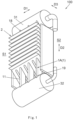
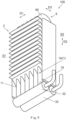
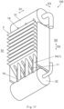
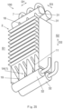
- a heat exchanger 100 includes: a plurality of rows of heat exchange tubes arranged in a first direction D1, each row of heat exchange tubes being composed of one heat exchange tube 1 or a plurality of heat exchange tubes 1; and a plurality of fins 2 arranged in a second direction D2 perpendicular to the first direction D1.
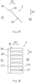
- Each of the plurality of fins 2 includes a fin body 20 and a plurality of heat exchange tube slots 21 formed in the fin body 20, the one heat exchange tube 1 or the plurality of heat exchange tubes 1 of each row of heat exchange tubes of the plurality of rows of heat exchange tubes being inserted into one heat exchange tube slot 21 of the plurality of heat exchange tube slots 21; and a length of at least one heat exchange tube slot 21 of the plurality of heat exchange tube slots 21 of at least one fin 2 of the plurality of fins 2 in a third direction D3 perpendicular to the first direction D1 and the second direction D2 being greater than a heat exchange tube size of the row of heat exchange tubes inserted into the at least one heat exchange tube slot 21 in the third direction D3 to form a gap 5 for passage of water in the at least one heat exchange tube slot 21.
- the heat exchange tube size is a size of the one heat exchange tube 1 in the third direction D3
- the heat exchange tube size is the sum of the sizes of the plurality of heat exchange tubes 1 in the third direction D3.
- the gap 5 forms a drainage passage through which defrosting water may quickly flow away, thereby improving the performance of the heat exchanger under frosting conditions.
- a ratio of the volume Vg of the defrosting water generated by the heat exchanger 100 to the volume Vp of the drainage passage of the heat exchanger 100 may satisfy the following relationship of: V g V p ⁇ R where R is a predetermined value, for example, R may be equal to 90, 110, 130, 150, 170, 190, 210, etc., or may be within a certain range, for example, within a range of 80 to 260.
- the fins 2 and the heat exchange tubes 1 of the heat exchanger 100 may satisfy this relationship to ensure an appropriate flow rate for discharging the defrosting water.
- the heat exchanger 100 when the volume of the generated defrosting water is larger and the volume of the drainage passage is smaller, the defrosting water is discharged more slowly; and when the volume of the generated defrosting water is smaller and the volume of the drainage passage is larger, the defrosting water is discharged more quickly.
- the ratio of the volume of the generated defrosting water to the volume of the drainage passage is less than the predetermined value, thereby ensuring the appropriate flow rate for discharging the defrosting water.
- At least a portion of the heat exchange tube 1 may extend substantially vertically, for example, the heat exchange tube 1 may extend substantially vertically.
- at least a portion of the heat exchange tube 1 may also extend substantially horizontally or obliquely, for example, the heat exchange tube 1 may extend substantially horizontally or obliquely.
- at least one row of heat exchange tubes is composed of a plurality of heat exchange tubes 1, and there may be a gap 5 between at least two adjacent heat exchange tubes 1 of the plurality of heat exchange tubes 1.
- a size of the gap 5 in the first direction D1 is equal to a width of the heat exchange tube slot 21 at least in the middle of the gap 5 in the third direction D3. That is, the gap 5 occupies the entire width of the heat exchange tube slot 21 at least in the middle of the gap 5, thereby ensuring that water can pass through the gap 5, and the gap 5 will not be blocked or partially blocked by solder during welding process, and preventing water from being not able to flow quickly through the gap 5 in the case that the gap 5 is too small or there is solder in gap 5.
- a size of the gap 5 in at least one heat exchange tube slot 21 of the plurality of heat exchange tube slots 21 in the third direction D3 is greater than or equal to that of the one heat exchange tube 1 or one heat exchange tube 1 of the plurality of heat exchange tubes 1 of the row of heat exchange tubes in the at least one heat exchange tube slot 21 in the third direction D3.
- the heat exchange tube 1 includes a first tube edge 11 and a second tube edge 12, the first tube edge 11 and the second tube edge 12 of the heat exchange tube 1 being respectively positioned on the outermost sides of the heat exchange tube 1 in the third direction D3, and the heat exchanger 100 has a first side S1 and a second side S2 opposite to each other in the third direction D3, the first tube edge 11 of the heat exchange tube 1 being closer to the first side S1 of the heat exchanger 100 than the second tube edge 12 of the heat exchange tube 1 in the third direction D3.
- the heat exchange tube slot 21 of the fin 2 has a first slot edge 211 and a second slot edge 212, the first slot edge 211 and the second slot edge 212 of the heat exchange tube slot 21 of the fin 2 being respectively positioned on the outermost sides of the heat exchange tube slot 21 in the third direction D3, and the first slot edge 211 of the heat exchange tube slot 21 of the fin 2 being closer to the first side S1 of the heat exchanger 100 than the second slot edge 212 of the heat exchange tube slot 21 of the fin 2 in the third direction D3.
- the heat exchange tube slot 21 of the plurality of fins 2 may have an opening towards the second side S2 of the heat exchanger 100, or the heat exchange tube slot 21 of the plurality of fins 2 has no opening and is a closed heat exchange tube slot.
- Each of at least some fins 2 may be formed by one plate. For example, all fins 2 may be formed from one plate.
- the one heat exchange tube 1 or the plurality of heat exchange tubes 1 of the row of the heat exchange tubes may be positioned between the first slot edge 211 and the second slot edge 212 of the heat exchange tube slot 21 of the fin 2 in the third direction D3.
- the one heat exchange tube 1 or the plurality of heat exchange tubes 1 of the row of heat exchange tubes may be positioned between the first slot edge 211 and the second slot edge 212 of the heat exchange tube slot 21 of the fin 2 in the third direction D3.
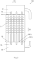
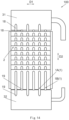
- the heat exchange tubes 1 of the plurality of rows of heat exchange tubes include a plurality of columns of heat exchange tubes arranged in the third direction D3, each column of heat exchange tubes of the plurality of columns of heat exchange tubes includes a plurality of heat exchange tubes 1 arranged in the first direction D1.
- a first column of heat exchange tubes includes a plurality of heat exchange tubes 1A
- a second column of heat exchange tubes includes a plurality of heat exchange tubes 1B
- a third column of heat exchange tubes includes a plurality of heat exchange tubes 1C
- a fourth column of heat exchange tubes includes a plurality of heat exchange tubes 1D, and so on.
- orthographic projections of the heat exchange tubes 1 of two adjacent rows of heat exchange tubes in a plane perpendicular to the first direction D1 are separated from each other in the third direction D3.
- the heat exchange tubes 1 of two adjacent rows of heat exchange tubes are displaced from each other in the third direction D3.
- the heat exchange tubes 1 of at least one column of heat exchange tubes 1 of the plurality of columns of heat exchange tubes may have substantially the same size in the third direction D3.
- the heat exchange tubes 1 of each column of heat exchange tubes of the plurality of columns of heat exchange tubes and the heat exchange tubes 1 of the adjacent column of heat exchange tubes 1 of the plurality of columns of heat exchange tubes may be separated from each other in the third direction D3.
- the plurality of gaps 5 include a plurality of columns of gaps arranged in the third direction D3, each column of gaps of the plurality of columns of gaps including a plurality of gaps arranged in the first direction D1. According to the examples of the present invention, the gaps 5 in at least two adjacent heat exchange tube slots 21 are displaced from each other in the third direction D3.
- the plurality of columns of heat exchange tubes are arranged sequentially from the first side S1 to the second side S2 of the heat exchanger 100 in a third direction D3; and there are gaps 5 between the first slot edges 211 of the heat exchange tube slots 21 and the first tube edge 11 of the heat exchange tubes 1 of the second column of heat exchange tubes of the plurality of columns of heat exchange tubes inserted into the heat exchange tube slots 21 in the third direction D3.
- the first slot edges 211 of the heat exchange tube slots 21 and the first tube edges 11 of the heat exchange tubes 1 of the first column of heat exchange tubes of the plurality of columns of heat exchange tubes inserted into the heat exchange tube slots 21 are substantially aligned with each other in the third direction D3.
- the first column of heat exchange tubes includes the plurality of heat exchange tubes 1A
- the second column of heat exchange tubes includes the plurality of heat exchange tubes 1B
- the third column of heat exchange tubes includes the plurality of heat exchange tubes 1C
- the fourth column of heat exchange tubes includes the plurality of heat exchange tubes 1D, and so on.
- the plurality of columns of heat exchange tubes are arranged sequentially from the second side S2 to the first side S1 of the heat exchanger 100 in the third direction D3; and there are gaps 5 between the second slot edges 212 of the heat exchange tube slots 21 and the second tube edges 12 of the heat exchange tubes 1 of the second column of heat exchange tubes of the plurality of columns of heat exchange tubes inserted into the heat exchange tube slots 21 in the third direction D3.
- the second slot edges 212 of the heat exchange tube slots 21 and the second tube edges 12 of the heat exchange tubes 1 of the first column of heat exchange tubes of the plurality of columns of heat exchange tubes inserted into the heat exchange tube slots 21 are substantially aligned with in the third direction D3.
- the first column of heat exchange tubes includes the plurality of heat exchange tubes 1D
- the second column of heat exchange tubes includes the plurality of heat exchange tubes 1C
- the third column of heat exchange tubes includes the plurality of heat exchange tubes 1B
- the fourth column of heat exchange tubes includes the plurality of heat exchange tubes 1A, and so on.
- a plurality of columns of gaps are arranged sequentially from the second side S2 to the first side S1 of the heat exchanger 100 in the third direction D3; the gaps 5 of odd numbered columns of gaps of the plurality of columns of gaps are formed in some heat exchange tube slots 21 of the plurality of heat exchange tube slots 21, and the gaps 5 of even numbered columns of gaps of the plurality of columns of gaps are formed in some other heat exchange tube slots 21 of the plurality of heat exchange tube slots 21; and the some heat exchange tube slots 21 and the some other heat exchange tube slots 21 are alternately arranged in the first direction D1.
- the plurality of columns of heat exchange tubes are arranged sequentially from the first side S1 to the second side S2 of the heat exchanger 100 in the third direction D3; and the first slot edges 211 of some heat exchange tube slots 21, into which the heat exchange tubes 1 of the second column of heat exchange tubes of the plurality of columns of heat exchange tubes are inserted, are closer to the second side S2 of the heat exchanger 100 than the first slot edges 211 of some other heat exchange tube slots 21, into which the heat exchange tubes 1 of the first column of heat exchange tubes of the plurality of columns of heat exchange tubes are inserted.
- the first column of heat exchange tubes includes the plurality of heat exchange tubes 1A
- the second column of heat exchange tubes includes the plurality of heat exchange tubes 1B
- the third column of heat exchange tubes includes the plurality of heat exchange tubes 1C
- the fourth column of heat exchange tubes includes the plurality of heat exchange tubes 1D, and so on.
- a larger plane is provided locally for the flowing of the defrosting water, and the surface tension of this continuous plane can promote the faster flowing of the defrosting water, improving the performance of the heat exchanger under the frosting conditions.
- the heat exchange tubes 1 of odd numbered columns of heat exchange tubes of the plurality columns of heat exchange tubes are provided in some heat exchange tube slots 21 of the plurality of heat exchange tube slots 21, and the heat exchange tubes 1 of even numbered columns of heat exchange tubes of the plurality columns of heat exchange tubes are provided in some other heat exchange tube slots 21 of the plurality of heat exchange tube slots 21; and the some heat exchange tube slots 21 and the some other heat exchange tube slots 21 are alternately arranged in the first direction D1.
- the first column of heat exchange tubes includes the plurality of heat exchange tubes 1A
- the second column of heat exchange tubes includes the plurality of heat exchange tubes 1B
- the third column of heat exchange tubes includes the plurality of heat exchange tubes 1C
- the fourth column of heat exchange tubes includes the plurality of heat exchange tubes 1D, and so on.
- the first column of heat exchange tubes includes the plurality of heat exchange tubes 1D
- the second column of heat exchange tubes includes the plurality of heat exchange tubes 1C
- the third column of heat exchange tubes includes the plurality of heat exchange tubes 1B
- the fourth column of heat exchange tubes includes the plurality of heat exchange tubes 1A, and so on.
- the first tube edges 11 of the heat exchange tubes 1 of at least one column of heat exchange tubes of the plurality of columns of heat exchange tubes are substantially aligned with each other in the third direction D3, and/or, the second tube edges 12 of the heat exchange tubes 1 of the at least one column of heat exchange tubes of the plurality of columns of heat exchange tubes are substantially aligned with each other in the third direction D3.
- the first tube edge 11 of the one heat exchange tube 1 (or the first tube edge 11 of at least one heat exchange tube 1 of the plurality of heat exchange tubes 1) of at least one row of heat exchange tubes of the plurality of rows of heat exchange tubes and the first tube edge 11 of the one heat exchange tube 1 (or the first tube edge 11 of at least one heat exchange tube 1 of the plurality of heat exchange tubes 1) of at least another row of heat exchange tubes of the plurality of rows of heat exchange tubes are displaced from each other in the third direction D3; and/or, the second tube edge 12 of the one heat exchange tube 1 (or the second tube edge 12 of the at least one heat exchange tube 1 of the plurality of heat exchange tubes 1) of the at least one row of heat exchange tubes of the plurality of rows of heat exchange tubes and the second tube edge 12 of the one heat exchange tube 1 (or the second tube edge 12 of the at least one heat exchange tube 1 of the plurality of heat exchange tubes 1) of the at least another row of heat exchange tubes of the
- first tube edges 11 of at least some heat exchange tubes 1 of at least some rows of heat exchange tubes of the plurality of rows of heat exchange tubes and the first tube edges 11 of at least some heat exchange tubes 1 of at least some other rows of heat exchange tubes of the plurality of rows of heat exchange tubes are displaced from each other in the third direction D3; and/or, the second tube edges 12 of the at least some heat exchange tubes 1 of the at least some rows of heat exchange tubes of the plurality of rows of heat exchange tubes and the second tube edges 12 of the at least some heat exchange tubes 1 of the at least some other rows of heat exchange tubes of the plurality of rows of heat exchange tubes are displaced from each other in the third direction D3.
- the first slot edge 211 of at least one heat exchanger slot 21 of the plurality of heat exchange tube slots 21 of at least one fin 2 of the plurality of fins 2 and the first slot edge 211 of at least another heat exchanger slot 21 of the plurality of heat exchange tube slots 21 of the at least one fin 2 of the plurality of fins 2 are displaced from each other in the third direction D3.
- the second slot edge 212 of the at least one heat exchanger slot 21 of the plurality of heat exchange tube slots 21 of the at least one fin 2 of the plurality of fins 2 and the second slot edge 212 of the at least another heat exchanger slot 21 of the plurality of heat exchange tube slots 21 of the at least one fin 2 of the plurality of fins 2 are substantially aligned with each other in the third direction.
- the second slot edge 212 of the at least one heat exchange tube slot 21 of the plurality of heat exchange tube slots 21 of the at least one fin 2 of the plurality of fins 2 and the second slot edge 212 of the at least another heat exchange tube slot 21 of the plurality of heat exchange tube slots 21 of the at least one fin 2 of the plurality of fins 2 may also displaced from each other in the third direction D3.
- the first slot edges 211 of the heat exchange tube slots 21 of the plurality of fins 2 are substantially aligned with each other in the third direction D3, and the second slot edges 212 of the heat exchange tube slots 21 of the plurality of fins 2 are substantially aligned with each other in the third direction D3.
- the heat exchange tube slots 21 of the plurality of fins 2 may have approximately the same size in the third direction D3.
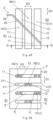
- the heat exchange tube 1 of the plurality of rows of heat exchange tubes includes a first end 18 positioned on one side of the heat exchange tube 1 in the second direction D2 and a second end 19 positioned on the other side of the heat exchange tube 1 in the second direction D2.
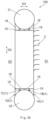
- the heat exchanger 100 further includes: a first header 31 connected and fluidly communicated with the first ends 18 of the heat exchange tubes 1 of the plurality of rows of heat exchange tubes; and a second header 32 connected and fluidly communicated with the second ends 19 of the heat exchange tubes 1 of the plurality of rows of heat exchange tubes.
- the heat exchange tubes 1 of the plurality of rows of heat exchange tubes may be arranged into one, two, three, four or more columns of the heat exchange tubes.
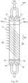
- the heat exchanger 100 further includes: a first header 31 connected and fluidly communicated with the first ends 18 of the heat exchange tubes 1 of the plurality of columns of heat exchange tubes; and two second headers 32, one of the two second headers 32 being connected and fluidly communicated with the second ends 19 of the heat exchange tubes 1 of at least one column of the heat exchange tubes 1 of the plurality of columns of heat exchange tubes, and the other of the two second headers 32 being connected and fluidly communicated with the second ends 19 of the heat exchange tubes 1 of at least another column of the heat exchange tubes of the plurality of columns of heat exchange tubes.
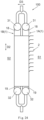
- the heat exchanger 100 further includes: two first headers 31 and two second headers 32, one of the two first headers 31 and one of the two second headers 32 being connected and fluidly communicated with the first ends 18 and the second ends 19 of the heat exchange tubes 1 of at least one column of the heat exchange tubes of the plurality of columns of heat exchange tubes, respectively, and the other of the two first headers 31 and the other of the two second headers 32 being connected and fluidly communicated with the first ends 18 and the second ends 19 of the heat exchange tubes 1 of at least another column of the heat exchange tubes of the plurality of columns of heat exchange tubes, respectively.
- two first headers 31 and two second headers 32 one of the two first headers 31 and one of the two second headers 32 being connected and fluidly communicated with the first ends 18 and the second ends 19 of the heat exchange tubes 1 of at least another column of the heat exchange tubes of the plurality of columns of heat exchange tubes, respectively.
- the two first headers 31 may be connected with a refrigerant inlet pipe or a refrigerant outlet pipe
- the two second headers 32 may be connected with a refrigerant outlet pipe or a refrigerant inlet pipe.
- the two first headers 31 may be connected with each other by a connection pipe 7, and the two second headers 32 may be connected with the refrigerant inlet pipe and the refrigerant outlet pipe, respectively.
- the connection pipe 7 may be connected with the refrigerant inlet pipe and the refrigerant outlet pipe, respectively.
- the heat exchanger 100 further includes: a connection portion 6, by which the first ends 18 of the heat exchange tubes 1 of one column of heat exchange tubes of the plurality of columns of heat exchange tubes are connected and fluidly communicated with the first ends 18 of the heat exchange tubes 1 of another column of heat exchange tubes of the plurality of columns of heat exchange tubes; and two second headers 32, one of the two second headers 32 being connected and fluidly communicated with the second ends 19 of the heat exchange tubes 1 of the one column of heat exchange tubes, and the other of the two second headers 32 being connected and fluidly communicated with the second ends 19 of the heat exchange tubes 1 of the another column of heat exchange tubes.
- the connection portion 6 may be a plurality of connection tubes 60, by which the first ends 18 of the heat exchange tubes 1 of the one column of heat exchange tubes are connected and fluidly communicated with the first ends 18 of the heat exchange tubes 1 of the another column of heat exchange tubes, respectively.
- the connection portion 6 may also enable the first ends 18 of the heat exchange tubes 1 of the one column of heat exchange tubes to be connected and fluidly communicated with the first ends 18 of the heat exchange tubes 1 of the another column of heat exchange tubes, but not being in one-to-one correspondence relationship.
- the heat exchange tube 1 of the one column of heat exchange tubes, the connection tube 60, and the heat exchange tube 1 of the another column of heat exchange tubes, which are connected with each other, may be formed by bending one tube.
- the two second headers 32 may be connected to the refrigerant inlet pipe and the refrigerant outlet pipe, respectively.
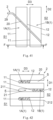
- the fin bodies 20 of the plurality of fins 2 when viewed in the first direction D1, are inclined relative to the third direction D3.
- the fin bodies 20 of the fins 2 may be parallel to the first direction D1.
- an angle between the fin bodies 20 of the plurality of fins 2 and the third direction D3 is less than or equal to 45 degrees.
- Each of the plurality of fins 2 also includes a fin segment 29 extending from an edge of the fin body 20 on the first side S1 of the heat exchanger 100 in the third direction D3.
- the fin segment 29 may be parallel to the first direction D1.
- the fin bodies 20 of the plurality of fins 2 may also be parallel to the third direction D3.
- the fin bodies 20 of the plurality of fins 2 are inclined relative to the third direction D3, therefore, the inclined fin bodies 20 may further promote the rapid discharge of the defrosting water and improve the performance of the heat exchanger under the frosting conditions.
- At least two heat exchange tube slots 21 of the plurality of heat exchange tube slots 21 of at least one fin 2 of the plurality of fins 2 have substantially the same size in the third direction D3 and the heat exchange tubes 1 of the rows of heat exchange tubes inserted into the at least two heat exchange tube slots 21 has substantially the same size in the third direction D3.
- the heat exchange tube slots 21 of the plurality of fins 2 have substantially the same size in the third direction D3
- the heat exchange tubes of the plurality of rows of heat exchange tubes have substantially the same size in the third direction D3.
- the heat exchange tube slot 21 of the plurality of fins 2 has an opening towards the second side S2 of the heat exchanger 100, thereby making assembly simple.
- the gap forms a drainage passage through which the defrosting water may quickly flow away, improving the performance under the frosting conditions.
- the fin bodies 20 of the plurality of fins 2 are inclined relative to the third direction D3, therefore, the inclined fin bodies 20 may further promote the rapid discharge of the defrosting water and improve the performance of the heat exchanger under the frosting conditions.
- At least two heat exchange tube slots 21 of the plurality of heat exchange tube slots 21 of at least one fin 2 of the plurality of fins 2 have substantially the same size in the third direction D3, and the heat exchange tubes 1 of the rows of heat exchange tubes inserted into the at least two heat exchange tube slots 21 has different sizes in the third direction D3.
- the heat exchange tube slots 21 of the plurality of fins 2 have substantially the same size in the third direction D3, and the heat exchange tubes 1 of the plurality of rows of heat exchange tubes has different sizes in the third direction D3.
- the gap forms a drainage passage through which the defrosting water may quickly flow away, improving the performance under the frosting conditions.
- the gaps with different sizes are formed, thereby forming the drainage passages with different sizes, therefore, the discharge path of the defrosting water are more flexibly and effectively managed, improving the performance of the heat exchanger under the frosting conditions.
- the fin bodies 20 of the plurality of fins 2 are inclined relative to the third direction D3, therefore, the inclined fin bodies 20 may further promote the rapid discharge of the defrosting water and improve the performance of the heat exchanger under the frosting conditions.
- At least two heat exchange tube slots 21 of the plurality of heat exchange tube slots 21 of at least one fin 2 of the plurality of fins 2 have different sizes in the third direction D3, and the heat exchange tubes 1 of the rows of heat exchange tubes inserted into the at least two heat exchange tube slots 21 have substantially the same size in the third direction D3.
- the heat exchange tube slots 21 of the plurality of fins 2 have different sizes in the third direction D3, and the heat exchange tubes 1 of the plurality of rows of heat exchange tubes have substantially the same size in the third direction D3.
- the first slot edges 211 of the heat exchange tube slots are displaced from each other in the third direction D3, providing a larger plane for the flowing of the defrosting water locally.
- the surface tension of this continuous plane can promote the faster flowing of the defrosting water, improving the performance of the heat exchanger under the frosting conditions.
- the gaps with different sizes are formed, thereby forming the drainage passages with different sizes, therefore, the discharge path of the defrosting water are more flexibly and effectively managed, improving the performance of the heat exchanger under the frosting conditions.
- the fin bodies 20 of the plurality of fins 2 are inclined relative to the third direction D3, therefore, the inclined fin bodies 20 may further promote the rapid discharge of the defrosting water and improve the performance of the heat exchanger under the frosting conditions.
- At least two heat exchange tube slots 21 of the plurality of heat exchange tube slots 21 of at least one fin 2 of the plurality of fins 2 have different sizes in the third direction D3, and the heat exchange tubes 1 of the rows of heat exchange tubes inserted into the at least two heat exchange tube slots 21 have different sizes in the third direction D3.
- the heat exchange tube slots 21 of the plurality of fins 2 have different sizes in the third direction D3, and the heat exchange tubes 1 of the plurality of rows of heat exchange tubes have different sizes in the third direction D3.
- the first slot edges 211 of the heat exchange tube slots are displaced from each other in the third direction D3, and the first tube edges 11 of the heat exchange tubes 1 are displaced from each other in the third direction D3, providing a larger plane for the flowing of the defrosting water locally.
- the surface tension of this continuous plane can promote the faster flowing of the defrosting water, improving the performance of the heat exchanger under the frosting conditions.
- the gaps with different sizes are formed, thereby forming the drainage passages with different sizes, therefore, the discharge path of the defrosting water are more flexibly and effectively managed, improving the performance of the heat exchanger under the frosting conditions.
- the fin bodies 20 of the plurality of fins 2 are inclined relative to the third direction D3, therefore, the inclined fin bodies 20 may further promote the rapid discharge of the defrosting water and improve the performance of the heat exchanger under frosting conditions.
- the heat exchange tube 1 may be a flat tube or any heat exchange tube having two planes which are substantially parallel to each other.
- a width of the heat exchange tube 1 or a size of the heat exchange tube 1 in the third direction is greater than a thickness of the heat exchange tube 1 or a size of the heat exchange tube 1 in the first direction.
- a length of the heat exchange tube slot 21 or a size of the heat exchange tube slot 21 in the third direction is greater than a width of the heat exchange tube slot 21 or a size of the heat exchange tube slot 21 in the first direction.
- the thickness of the heat exchange tube 1 may be less than or equal to the width of the heat exchange tube slot 21.
- a bent heat exchanger 100' is formed by bending the above-mentioned heat exchanger 100.
- the heat exchanger 100 is bent along a bending line of the heat exchanger 100 in the middle of the first direction D1 and parallel to the second direction, so that at least one portion of the two portions of the heat exchanger 100 on both sides of the bending line is towards the second side S2 of the heat exchanger 100, i.e., one side on which the opening of the heat exchange tube slot 21 is positioned.
- An angle between the two portions of the heat exchanger 100 may be any appropriate angle.
- an air conditioning system includes: the above-mentioned heat exchanger 100 or bent heat exchanger 100 '. More specifically, the air conditioning system includes: a compressor, a condenser, an evaporator, an expansion valve, etc.. At least one of the condenser and the evaporator may be the above-mentioned heat exchanger 100 or bent heat exchanger 100'.
- the heat exchanger, the bent heat exchanger and the air conditioning system having the heat exchanger or the bent heat exchanger according to the embodiments of the present invention for example, the performance of the heat exchanger and the air conditioning system can be improved.
- the flow path of the defrosting water can be flexibly managed, at the same time, combined with the inclined structure of the fin, the flowing of the defrosting water is accelerated, further enhancing the discharge of the defrosting water, and improving the performance of the heat exchanger and the air conditioning system under the frosting conditions.
Landscapes
- Engineering & Computer Science (AREA)
- Physics & Mathematics (AREA)
- Thermal Sciences (AREA)
- Mechanical Engineering (AREA)
- General Engineering & Computer Science (AREA)
- Geometry (AREA)
- Heat-Exchange Devices With Radiators And Conduit Assemblies (AREA)
- Other Air-Conditioning Systems (AREA)
Abstract
The present invention discloses a heat exchanger, a bent heat exchanger formed by bending the heat exchanger, and an air conditioning system having the heat exchanger or the bent heat exchanger. The heat exchanger includes: a plurality of rows of heat exchange tubes arranged in a first direction; and a plurality of fins arranged in a second direction perpendicular to the first direction. Each of the plurality of fins includes a fin body and a plurality of heat exchange tube slots formed in the fin body, one or more heat exchange tubes of each row of heat exchange tubes of the plurality of rows of heat exchange tubes being inserted into one heat exchange tube slot of the plurality of heat exchange tube slots; and a length of at least one heat exchange tube slot of the plurality of heat exchange tube slots of at least one fin of the plurality of fins in a third direction perpendicular to the first direction and the second direction is greater than a heat exchange tube size of the row of heat exchange tubes inserted into the at least one heat exchange tube slot in the third direction to form a gap for passage of water in the at least one heat exchange tube slot, thereby improving the performance of the heat exchanger, bent heat exchanger and air conditioning system.
Description
- Embodiments of the present invention relate to a heat exchanger, a bent heat exchanger formed by bending the heat exchanger, and an air conditioning system having the heat exchanger or the bent heat exchanger.
- A heat exchanger includes heat exchange tubes and fins having heat exchange tube slots. The heat exchange tube slots have openings on a side of the heat exchanger, or the heat exchange tube slots have no opening. The heat exchange tubes are inserted into the heat exchange tube slots of the fins.
- An object of embodiments of the present invention is to provide a heat exchanger, a bent heat exchanger formed by bending the heat exchanger, and an air conditioning system having the heat exchanger or the bent heat exchanger, thereby, for example, improving the performance of the heat exchanger, the bent heat exchanger and the air conditioning system.
- Embodiments of the present invention provide a heat exchanger including: a heat exchanger a plurality of rows of heat exchange tubes arranged in a first direction, each row of heat exchange tubes includes one heat exchange tube or a plurality of heat exchange tubes; and a plurality of fins arranged in a second direction perpendicular to the first direction, wherein each of the plurality of fins includes a fin body and a plurality of heat exchange tube slots formed in the fin body, the one heat exchange tube of each row of heat exchange tubes of the plurality of rows of heat exchange tubes being inserted into one heat exchange tube slot of the plurality of heat exchange tube slots, or, the plurality of heat exchange tubes of each row of heat exchange tubes of the plurality of rows of heat exchange tubes being inserted into one heat exchange tube slot of the plurality of heat exchange tube slots; and a length of at least one heat exchange tube slot, in a third direction perpendicular to the first direction and the second direction, of the plurality of heat exchange tube slots of at least one fin of the plurality of fins is greater than a heat exchange tube size of the row of heat exchange tubes inserted into the at least one heat exchange tube slot in the third direction to form a gap for passage of water in the at least one heat exchange tube slot, in the case that the row of heat exchange tubes includes the one heat exchange tube, the heat exchange tube size is a size of the one heat exchange tube in the third direction, and in the case that the row of heat exchange tubes includes the plurality of heat exchange tubes, the heat exchange tube size is a sum of sizes of the plurality of heat exchange tubes in the third direction.
- According to embodiments of the present invention, the fins and the heat exchange tubes of the heat exchanger satisfy the following relationship of:

- According to embodiments of the present invention, the predetermined value R is equal to 150.
- According to embodiments of the present invention, at least one row of heat exchange tubes includes the plurality of heat exchange tubes, and there is a gap between at least two adjacent heat exchange tubes of the plurality of heat exchange tubes.
- According to embodiments of the present invention, the heat exchange tube includes a first tube edge and a second tube edge, the first tube edge and the second tube edge of the heat exchange tube being respectively positioned on the outermost sides of the heat exchange tube in the third direction, and the heat exchanger has a first side and a second side opposite to each other in the third direction, the first tube edge of the heat exchange tube being closer to the first side of the heat exchanger than the second tube edge of the heat exchange tube in the third direction; the heat exchange tube slot of the fin has a first slot edge and a second slot edge, the first slot edge and the second slot edge of the heat exchange tube slot of the fin being respectively positioned on the outermost sides of the heat exchange tube slot in the third direction, and the first slot edge of the heat exchange tube slot of the fin being closer to the first side of the heat exchanger than the second slot edge of the heat exchange tube slot of the fin in the third direction; and there is a gap in the third direction between the first slot edge of at least one heat exchange tube slot of the plurality of heat exchange tube slots of at least one fin of the plurality of fins and the first tube edge of the one heat exchange tube of the row of heat exchange tubes inserted into the at least one heat exchange tube slot, or, there is a gap in the third direction between the first slot edge of the at least one heat exchange tube slot of the plurality of heat exchange tube slots of the at least one fin of the plurality of fins and the first tube edge of one heat exchange tube, of the plurality of heat exchange tubes closest to the first slot edge, of the row of heat exchange tubes inserted into the at least one heat exchange tube slot; and/or there is a gap in the third direction between the second slot edge of the at least one heat exchange tube slot of the plurality of heat exchange tube slots of at least one fin of the plurality of fins and the second tube edge of the one heat exchange tube of the row of heat exchange tubes inserted into the at least one heat exchange tube slot, or, there is a gap in the third direction between the second slot edge of the at least one heat exchange tube slot of the plurality of heat exchange tube slots of the at least one fin of the plurality of fins and the second tube edge of one heat exchange tube, of the plurality of heat exchange tubes closest to the second slot edge, of the row of heat exchange tubes inserted into the at least one heat exchange tube slot.
- According to embodiments of the present invention, at least in the middle of the gap in the third direction, a size of the gap in the first direction is equal to a width of the heat exchange tube slot; and/or, a size of the gap in at least one heat exchange tube slot of the plurality of heat exchange tube slots in the third direction is greater than or equal to that of the one heat exchange tube of the row of heat exchange tubes in the at least one heat exchange tube slot in the third direction, or, the size of the gap in the at least one heat exchange tube slot of the plurality of heat exchange tube slots in the third direction is greater than or equal to that of one heat exchange tube of the plurality of heat exchange tubes of the row of heat exchange tubes in the at least one heat exchange tube slot in the third direction.
- According to embodiments of the present invention, the heat exchange tube includes a first tube edge and a second tube edge, the first tube edge and the second tube edge of the heat exchange tube being respectively positioned on the outermost sides of the heat exchange tube in the third direction, and the heat exchanger has a first side and a second side opposite to each other in the third direction, the first tube edge of the heat exchange tube being closer to the first side of the heat exchanger than the second tube edge of the heat exchange tube in the third direction; the heat exchange tube slot of the fin has a first slot edge and a second slot edge, the first slot edge and the second slot edge of the heat exchange tube slot of the fin being respectively positioned on the outermost sides of the heat exchange tube slot in the third direction, and the first slot edge of the heat exchange tube slot of the fin being closer to the first side of the heat exchanger than the second slot edge of the heat exchange tube slot of the fin in the third direction; and the heat exchange tubes of the plurality of rows of heat exchange tubes include a plurality of columns of heat exchange tubes arranged in the third direction, each column of heat exchange tubes of the plurality of columns of heat exchange tubes including a plurality of heat exchange tubes arranged in the first direction.
- According to embodiments of the present invention, orthogonal projections of the heat exchange tubes of two adjacent rows of heat exchange tubes in a plane perpendicular to the first direction are separated from each other in the third direction.
- According to embodiments of the present invention, the heat exchange tubes of two adjacent rows of heat exchange tubes are displaced from each other in the third direction.
- According to embodiments of the present invention, a plurality of gaps for the drainage of water are formed between at least some heat exchange tube slots of at least some fins of the plurality of fins and the heat exchange tubes of the rows of heat exchange tubes inserted into the at least some heat exchange tube slots, the plurality of gaps including a plurality of columns of gaps arranged in the third direction, each column of gaps of the plurality of columns of gaps including a plurality of gaps arranged in the first direction.
- According to embodiments of the present invention, the gaps in at least two adjacent heat exchange tube slots are displaced from each other in the third direction.
- According to embodiments of the present invention, the plurality of columns of heat exchange tubes are arranged sequentially from the first side to the second side of the heat exchanger in the third direction; and there are gaps between the first slot edges of the heat exchange tube slots and the first tube edges of the heat exchange tubes of a second column of heat exchange tubes of the plurality of columns of heat exchange tubes inserted into the heat exchange tube slots in the third direction.
- According to embodiments of the present invention, the first slot edges of the heat exchange tube slots and the first tube edges of the heat exchange tubes of a first column of heat exchange tubes of the plurality of columns of heat exchange tubes inserted into the heat exchange tube slots are substantially aligned with each other in the third direction.
- According to embodiments of the present invention, the plurality of columns of heat exchange tubes are arranged sequentially from the second side to the first side of the heat exchanger in the third direction; and there are gaps between the second slot edges of the heat exchange tube slots and the second tube edges of the heat exchange tubes of a second column of heat exchange tubes of the plurality of columns of heat exchange tubes inserted into the heat exchange tube slots in the third direction.
- According to embodiments of the present invention, the second slot edges of the heat exchange tube slots and the second tube edges of the heat exchange tubes of a first column of heat exchange tubes of the plurality of columns of heat exchange tubes inserted into the heat exchange tube slots are substantially aligned with in the third direction.
- According to embodiments of the present invention, the plurality of columns of heat exchange tubes are arranged sequentially from the first side to the second side of the heat exchanger in the third direction; and the first slot edges of some heat exchange tube slots, into which the heat exchange tubes of the second column of heat exchange tubes of the plurality columns of heat exchange tubes are inserted, are closer to the second side of the heat exchanger than the first slot edges of some other heat exchange tube slots, into which the heat exchange tubes of the first column of heat exchange tubes of the plurality columns of heat exchange tubes are inserted.
- According to embodiments of the present invention, the plurality of columns of gaps are arranged sequentially from the second side to the first side of the heat exchanger in the third direction; the gaps of odd numbered columns of gaps of the plurality of columns of gaps are formed in some heat exchange tube slots of the plurality of heat exchange tube slots, and the gaps of even numbered columns of gaps of the plurality of columns of gaps are formed in some other heat exchange tube slots of the plurality of heat exchange tube slots; and the some heat exchange tube slots and the some other heat exchange tube slots are arranged alternately in the first direction.
- According to embodiments of the present invention, the heat exchange tubes of odd numbered columns of heat exchange tubes of the plurality of columns of heat exchange tubes are provided in some heat exchange tube slots of the plurality of heat exchange tube slots, and the heat exchange tubes of even numbered columns of heat exchange tubes of the plurality of columns of heat exchange tubes are formed in some other heat exchange tube slots of the plurality of heat exchange tube slots; and the some heat exchange tube slots and the some other heat exchange tube slots are arranged alternately in the first direction.
- According to embodiments of the present invention, the first tube edges of the heat exchange tubes of at least one column of heat exchange tubes of the plurality of columns of heat exchange tubes are substantially aligned with each other in the third direction, and/or the second tube edges of the heat exchange tubes of the at least one column of heat exchange tubes of the plurality of columns of heat exchange tubes are substantially aligned with each other in the third direction.
- According to embodiments of the present invention, the heat exchange tubes of at least one column of heat exchange tubes of the plurality of columns of heat exchange tubes have substantially the same size in the third direction.
- According to embodiments of the present invention, the heat exchange tube includes a first tube edge and a second tube edge, the first tube edge and the second tube edge of the heat exchange tube being respectively positioned on the outermost sides of the heat exchange tube in the third direction, and the heat exchanger has a first side and a second side opposite to each other in the third direction, the first tube edge of the heat exchange tube being closer to the first side of the heat exchanger than the second tube edge of the heat exchange tube in the third direction; and the first tube edge of the one heat exchange tube (, or the first tube edge of at least one heat exchange tube of the plurality of heat exchange tubes,) of at least one row of heat exchange tubes of the plurality of rows of heat exchange tubes and the first tube edge of the one heat exchange tube (, or the first tube edge of at least one heat exchange tube of the plurality of heat exchange tubes,) of at least another row of heat exchange tubes of the plurality of rows of heat exchange tubes are displaced from each other in the third direction; and/or, the second tube edge of the one heat exchange tube (, or the second tube edge of the at least one heat exchange tube of the plurality of heat exchange tubes,) of the at least one row of heat exchange tubes of the plurality of rows of heat exchange tubes and the second tube edge of the one heat exchange tube (, or the second tube edge of the at least one heat exchange tube of the plurality of heat exchange tubes,) of the at least another row of heat exchange tubes of the plurality of rows of heat exchange tubes are displaced from each other in the third direction.
- According to embodiments of the present invention, the heat exchange tube slot of the fin has a first slot edge and a second slot edge, the first slot edge and the second slot edge of the heat exchange tube slot of the fin being respectively positioned on the outermost sides of the heat exchange tube slot in the third direction, and the first slot edge of the heat exchange tube slot of the fin being closer to the first side of the heat exchanger than the second slot edge of the heat exchange tube slot of the fin in the third direction; and the first slot edge of at least one heat exchange tube slot of the plurality of heat exchange tube slots of at least one fin of the plurality of fins and the first slot edge of at least another heat exchange tube slot of the plurality of heat exchange tube slots of the at least one fin of the plurality of fins are displaced from each other in the third direction.
- According to embodiments of the present invention, the second slot edge of the at least one heat exchange tube slot of the plurality of heat exchange tube slots of the at least one fin of the plurality of fins and the second slot edge of the at least another heat exchange tube slot of the plurality of heat exchange tube slots of the at least one fin of the plurality of fins are displaced from each other in the third direction.
- According to embodiments of the present invention, the second slot edge of the at least one heat exchange tube slot of the plurality of heat exchange tube slots of the at least one fin of the plurality of fins and the second slot edge of the at least another heat exchange tube slot of the plurality of heat exchange tube slots of the at least one fin of the plurality of fins are substantially aligned with each other.
- According to embodiments of the present invention, the first slot edges of the heat exchange tube slots of the plurality of fins are substantially aligned with each other in the third direction, and the second slot edges of the heat exchange tube slots of the plurality of fins are substantially aligned with each other in the third direction.
- According to embodiments of the present invention, the heat exchange tube slots of the plurality of fins have substantially the same size in the third direction.
- According to embodiments of the present invention, the heat exchange tube of the plurality of rows of heat exchange tubes includes a first end positioned on one side of the heat exchange tube in the second direction and a second end positioned on the other side of the heat exchange tube in the second direction; and the heat exchanger further includes: a first header connected and fluidly communicated with the first ends of the heat exchange tubes of the plurality of rows of heat exchange tubes; and a second header connected and fluidly communicated with the second ends of the heat exchange tubes of the plurality of rows of heat exchange tubes.
- According to embodiments of the present invention, the heat exchange tube of the plurality of rows of heat exchange tubes includes a first end positioned on one side of the heat exchange tube in the second direction and a second end positioned on the other side of the heat exchange tube in the second direction; and the heat exchanger further includes: a first header connected and fluidly communicated with the first ends of the heat exchange tubes of the plurality of columns of heat exchange tubes; and two second headers, one of the two second headers being connected and fluidly communicated with the second ends of the heat exchange tubes of at least one column of heat exchange tubes of the plurality of columns of heat exchange tubes, and the other of the two second headers being connected and fluidly communicated with the second ends of the heat exchange tubes of at least another column of heat exchange tubes of the plurality of columns of heat exchange tubes.
- According to embodiments of the present invention, the heat exchange tube of the plurality of rows of heat exchange tubes includes a first end positioned on one side of the heat exchange tube in the second direction and a second end positioned on the other side of the heat exchange tube in the second direction; and the heat exchanger further includes: a connecting portion, the first ends of the heat exchange tubes of one column of heat exchange tubes of the plurality of columns of heat exchange tubes being connected and fluidly communicated with the first ends of the heat exchange tubes of another column of heat exchange tubes of the plurality of columns of heat exchange tubes by the connecting portion; and two second headers, one of the two second headers being connected and fluidly communicated with the second ends of the heat exchange tubes of the one column of heat exchange tubes, and the other of the two second headers being connected and fluidly communicated with the second ends of the heat exchange tubes of the another column of heat exchange tubes.
- According to embodiments of the present invention, the connection portion includes a plurality of connection tubes, the first ends of the heat exchange tubes of the one column of heat exchange tubes being connected and fluidly communicated with the first ends of the heat exchange tubes of the another column of heat exchange tubes by the plurality of connection tubes, respectively.
- According to embodiments of the present invention, the heat exchange tube of the one column of heat exchange tubes, the connection tube and the heat exchange tube of the another column of heat exchange tubes, which are interconnected, are formed by bending one tube.
- According to embodiments of the present invention, the heat exchange tube of the plurality of rows of heat exchange tubes includes a first end positioned on one side of the heat exchange tube in the second direction and a second end positioned on the other side of the heat exchange tube in the second direction; and the heat exchanger further includes: two first headers and two second headers, one of the two first headers and one of the two second headers being connected and fluidly communicated with the first ends and the second ends of the heat exchange tubes of at least one column of heat exchange tubes of the plurality of columns of heat exchange tubes, respectively, and the other of the two first headers and the other of the two second headers being connected and fluidly communicated with the first ends and the second ends of the heat exchange tubes of at least another column of heat exchange tubes of the plurality of columns of heat exchange tubes, respectively.
- According to embodiments of the present invention, the heat exchange tubes of each column of heat exchange tubes of the plurality of columns of heat exchange tubes and the heat exchange tubes of the adjacent column of heat exchange tubes of the plurality of columns of heat exchange tubes are separated from each other in the third direction.
- According to embodiments of the present invention, when viewed in the first direction, the fin bodies of the plurality of fins are inclined relative to the third direction.
- According to embodiments of the present invention, when viewed in the first direction, an angle between the fin bodies of the plurality of fins and the third direction is less than or equal to 45 degrees.
- According to embodiments of the present invention, the heat exchange tube slot of the fin has a first slot edge and a second slot edge, the first slot edge and the second slot edge of the heat exchange tube slot of the fin being respectively positioned on the outermost sides of the heat exchange tube slot in the third direction, and the first slot edge of the heat exchange tube slot of the fin being closer to the first side of the heat exchanger than the second slot edge of the heat exchange tube slot of the fin in the third direction; and each of the plurality of fins further includes: a fin segment extending from an edge of on the fin body on the first side of the heat exchanger in the third direction.
- According to embodiments of the present invention, at least two heat exchange tube slots of the plurality of heat exchange tube slots of at least one fin of the plurality of fins have substantially the same size in the third direction, and the heat exchange tubes of the rows of exchange tubes inserted into the at least two heat exchange tube slots have substantially the same size in the third direction.
- According to embodiments of the present invention, at least two heat exchange tube slots of the plurality of heat exchange tube slots of at least one fin of the plurality of fins have substantially the same size in the third direction, and the heat exchange tubes of the rows of exchange tubes inserted into the at least two heat exchange tube slots have different sizes in the third direction.
- According to embodiments of the present invention, at least two heat exchange tube slots of the plurality of heat exchange tube slots of at least one fin of the plurality of fins have different sizes in the third direction, and the heat exchange tubes of the rows of exchange tubes inserted into the at least two heat exchange tube slots have substantially the same size in the third direction.
- According to embodiments of the present invention, at least two heat exchange tube slots of the plurality of heat exchange tube slots of at least one fin of the plurality of fins have different sizes in the third direction, and the heat exchange tubes of the rows of exchange tubes inserted into the at least two heat exchange tube slots have different sizes in the third direction.
- According to embodiments of the present invention, the heat exchange tube slot of the fin has a first slot edge and a second slot edge, the first slot edge and the second slot edge of the heat exchange tube slot of the fin being respectively positioned on the outermost sides of the heat exchange tube slot in the third direction, and the first slot edge of the heat exchange tube slot of the fin being closer to the first side of the heat exchanger than the second slot edge of the heat exchange tube slot of the fin in the third direction; and the heat exchange tube slot of the plurality of fins has an opening towards the second side of the heat exchanger.
- According to embodiments of the present invention, in use, at least a portion of the heat exchange tube extends substantially vertically.
- According to embodiments of the present invention, each of at least some fins is formed by one plate.
- Embodiments of the present invention further provide a bent heat exchanger, the bent heat exchanger being formed by bending the above-mentioned heat exchanger.
- Embodiments of the present invention further provide an air conditioning system including the above-mentioned heater exchanger or bent heater exchanger.
- With the heat exchanger, the bent heater exchanger and the air conditioning system having the heat exchanger or the bent heater exchanger according to the embodiments of the present invention, for example, the performance of the heat exchanger, the bent heater exchanger and the air conditioning system may be improved.
-
-
Fig. 1 is a schematic perspective view of a heat exchanger according to an embodiment of the present invention; -
Fig. 2 is a schematic front view of the heat exchanger shown inFig. 1 ; -
Fig. 3 is a schematic right view of the heat exchanger shown inFig. 1 ; -
Fig. 4 is a schematic left view of the heat exchanger shown inFig. 1 ; -
Fig. 5 is a schematic perspective view of a heat exchanger according to an embodiment of the present invention; -
Fig. 6 is a schematic front view of the heat exchanger shown inFig. 5 ; -
Fig. 7 is a schematic right view of the heat exchanger shown inFig. 5 ; -
Fig. 8 is a schematic left view of the heat exchanger shown inFig. 5 ; -
Fig. 9 is a schematic perspective view of a heat exchanger according to an embodiment of the present invention; -
Fig. 10 is a schematic front view of the heat exchanger shown inFig. 9 ; -
Fig. 11 is a schematic right view of the heat exchanger shown inFig. 9 ; -
Fig. 12 is a schematic left view of the heat exchanger shown inFig. 9 ; -
Fig. 13 is a schematic perspective view of a heat exchanger according to an embodiment of the present invention; -
Fig. 14 is a schematic front view of the heat exchanger shown inFig. 13 ; -
Fig. 15 is a schematic right view of the heat exchanger shown inFig. 13 ; -
Fig. 16 is a schematic left view of the heat exchanger shown inFig. 13 ; -
Fig. 17 is a schematic perspective view of a heat exchanger according to an embodiment of the present invention; -
Fig. 18 is a schematic front view of the heat exchanger shown inFig. 17 ; -
Fig. 19 is a schematic right view of the heat exchanger shown inFig. 17 ; -
Fig. 20 is a schematic left view of the heat exchanger shown inFig. 17 ; -
Fig. 21 is a schematic perspective view of a heat exchanger according to an embodiment of the present invention; -
Fig. 22 is a schematic front view of the heat exchanger shown inFig. 21 ; -
Fig. 23 is a schematic right view of the heat exchanger shown inFig. 21 ; -
Fig. 24 is a schematic left view of the heat exchanger shown inFig. 21 ; -
Fig. 25 is a schematic perspective view of a heat exchanger according to an embodiment of the present invention; -
Fig. 26 is a schematic front view of the heat exchanger shown inFig. 25 ; -
Fig. 27 is a schematic right view of the heat exchanger shown inFig. 25 ; -
Fig. 28 is a schematic left view of the heat exchanger shown inFig. 25 ; -
Fig. 29 is a schematic right view of a fin of the heat exchanger shown inFigs. 1 ,5 ,9 ,13 ,17 ,21 and25 ; -
Fig. 30 is a schematic top view of the fin of the heat exchanger shown inFig. 29 ; -
Fig. 31 is a schematic right view of a heat exchanger, wherein only a portion of the heat exchange tubes and one fin are remained, according to an embodiment of the present invention; -
Fig. 32 is a schematic cross-sectional bottom view of the heat exchanger shown inFig. 31 taken along line A-A ofFig. 31 ; -
Fig. 33 is a schematic right view of a heat exchanger, wherein only a portion of the heat exchange tubes and one fin are remained, according to an embodiment of the present invention; -
Fig. 34 is a schematic cross-sectional bottom view of the heat exchanger shown inFig. 33 taken along line B-B ofFig. 33 ; -
Fig. 35 is a schematic right view of a heat exchanger, wherein only a portion of the heat exchange tubes and one fin are remained, according to an embodiment of the present invention; -
Fig. 36 is a schematic cross-sectional bottom view of the heat exchanger shown inFig. 35 taken along line C-C ofFig. 35 ; -
Fig. 37 is a schematic right view of a heat exchanger, wherein only a portion of the heat exchange tubes and one fin are remained, according to an embodiment of the present invention; -
Fig. 38 is a schematic cross-sectional bottom view of the heat exchanger shown inFig. 37 taken along line D-D ofFig. 37 ; -
Fig. 39 is a schematic right view of a heat exchanger, wherein only a portion of the heat exchange tubes and one fin are remained, according to an embodiment of the present invention; -
Fig. 40 is a schematic cross-sectional bottom view of the heat exchanger shown inFig. 39 taken along line E-E ofFig. 39 ; -
Fig. 41 is a schematic right view of a heat exchanger, wherein only a portion of the heat exchange tubes and one fin are remained, according to an embodiment of the present invention; -
Fig. 42 is a schematic cross-sectional bottom view of the heat exchanger shown inFig. 41 taken along line F-F ofFig. 41 ; -
Fig. 43 is a schematic right view of a heat exchanger, wherein only a portion of the heat exchange tubes and one fin are remained, according to an embodiment of the present invention; -
Fig. 44 is a schematic cross-sectional bottom view of the heat exchanger shown inFig. 43 , taken along line G-G inFig. 43 ; -
Fig. 45 is a schematic right view of a heat exchanger, wherein only a portion of the heat exchange tubes and one fin are remained, according to an embodiment of the present invention; -
Fig. 46 is a schematic cross-sectional bottom view of the heat exchanger shown inFig. 45 , taken along line H-H inFig. 45 ; -
Fig. 47 is a schematic right view of a heat exchanger, wherein only a portion of the heat exchange tubes and one fin are remained, according to an embodiment of the present invention; -
Fig. 48 is a schematic cross-sectional bottom view of the heat exchanger shown inFig. 47 , taken along line I-I inFig. 47 ; -
Fig. 49 is a schematic right view of a heat exchanger, wherein only a portion of the heat exchange tubes and one fin are remained, according to an embodiment of the present invention; -
Fig. 50 is a schematic cross-sectional bottom view of the heat exchanger shown inFig. 49 , taken along line J-J inFig. 49 ; -
Fig. 51 is a schematic perspective view of a bent heat exchanger according to an embodiment of the present invention; and -
Fig. 52 is a schematic top view of a portion of the bent heat exchanger shown inFig. 51 . - The present invention is further explained below by means of specific embodiments in conjunction with the drawings.
- Referring to
Figs. 1-50 , aheat exchanger 100 according to an embodiment of the present invention includes: a plurality of rows of heat exchange tubes arranged in a first direction D1, each row of heat exchange tubes being composed of oneheat exchange tube 1 or a plurality ofheat exchange tubes 1; and a plurality offins 2 arranged in a second direction D2 perpendicular to the first direction D1. Each of the plurality offins 2 includes afin body 20 and a plurality of heatexchange tube slots 21 formed in thefin body 20, the oneheat exchange tube 1 or the plurality ofheat exchange tubes 1 of each row of heat exchange tubes of the plurality of rows of heat exchange tubes being inserted into one heatexchange tube slot 21 of the plurality of heatexchange tube slots 21; and a length of at least one heatexchange tube slot 21 of the plurality of heatexchange tube slots 21 of at least onefin 2 of the plurality offins 2 in a third direction D3 perpendicular to the first direction D1 and the second direction D2 being greater than a heat exchange tube size of the row of heat exchange tubes inserted into the at least one heatexchange tube slot 21 in the third direction D3 to form agap 5 for passage of water in the at least one heatexchange tube slot 21. In the case that the row of heat exchange tubes is composed of the oneheat exchange tube 1, the heat exchange tube size is a size of the oneheat exchange tube 1 in the third direction D3, and in the case that the row of heat exchange tubes is composed of the plurality ofheat exchange tubes 1, the heat exchange tube size is the sum of the sizes of the plurality ofheat exchange tubes 1 in the third direction D3. For example, thegap 5 forms a drainage passage through which defrosting water may quickly flow away, thereby improving the performance of the heat exchanger under frosting conditions. - Referring to
Figs. 1-50 , in the embodiments of the present invention, a volume Vg of the defrosting water generated by theheat exchanger 100 and a volume Vp of the drainage passage of theheat exchanger 100 may be calculated as follows:

- Wf is a width of the
fin 2 in the third direction D3, - Lf is a length of the
fin 2 in thefirst direction D 1, - Wsi is a length of an ith heat
exchange tube slot 21 from one side to the other side of theheat exchanger 100 in the first direction D1, - Tsi is a width of the ith heat
exchange tube slot 21 from one side to the other side of theheat exchanger 100 in the first direction D1, - Pf is spacing between
adjacent fins 2, - Tf is a thickness of the
fin body 20 of thefin 2, - Wtij is a size of a jth
heat exchange tube 1, of the row of heat exchange tubes in the ith heatexchange tube slot 21 from one side to the other side of theheat exchanger 100 in the first direction D1, from a first side S1 to a second side S2 of theheat exchanger 100 in the third direction D3, when the row of heat exchange tubes is composed of oneheat exchange tube 1, j=1, - H is a size of a range of the plurality of
fins 2 arranged in the second direction D2, andθ is an angle between thefin body 20 of thefin 2 and the third direction D3. - According to the embodiments of the present invention, a ratio of the volume Vg of the defrosting water generated by the
heat exchanger 100 to the volume Vp of the drainage passage of theheat exchanger 100 may satisfy the following relationship of:
- The following relationship may be obtained by substituting the volume Vg of the defrosting water generated by the
heat exchanger 100 and the volume Vp of the drainage passage of theheat exchanger 100 into the above relationship:
- The
fins 2 and theheat exchange tubes 1 of theheat exchanger 100 may satisfy this relationship to ensure an appropriate flow rate for discharging the defrosting water. In case theheat exchanger 100 is used, when the volume of the generated defrosting water is larger and the volume of the drainage passage is smaller, the defrosting water is discharged more slowly; and when the volume of the generated defrosting water is smaller and the volume of the drainage passage is larger, the defrosting water is discharged more quickly. According to the embodiments of the present invention, the ratio of the volume of the generated defrosting water to the volume of the drainage passage is less than the predetermined value, thereby ensuring the appropriate flow rate for discharging the defrosting water. - Referring to
Figs. 1-50 , in use, at least a portion of theheat exchange tube 1 may extend substantially vertically, for example, theheat exchange tube 1 may extend substantially vertically. In addition, at least a portion of theheat exchange tube 1 may also extend substantially horizontally or obliquely, for example, theheat exchange tube 1 may extend substantially horizontally or obliquely. In the embodiments of the present invention, at least one row of heat exchange tubes is composed of a plurality ofheat exchange tubes 1, and there may be agap 5 between at least two adjacentheat exchange tubes 1 of the plurality ofheat exchange tubes 1. In the embodiments of the present invention, a size of thegap 5 in the first direction D1 is equal to a width of the heatexchange tube slot 21 at least in the middle of thegap 5 in the third direction D3. That is, thegap 5 occupies the entire width of the heatexchange tube slot 21 at least in the middle of thegap 5, thereby ensuring that water can pass through thegap 5, and thegap 5 will not be blocked or partially blocked by solder during welding process, and preventing water from being not able to flow quickly through thegap 5 in the case that thegap 5 is too small or there is solder ingap 5. In the embodiments of the present invention, a size of thegap 5 in at least one heatexchange tube slot 21 of the plurality of heatexchange tube slots 21 in the third direction D3 is greater than or equal to that of the oneheat exchange tube 1 or oneheat exchange tube 1 of the plurality ofheat exchange tubes 1 of the row of heat exchange tubes in the at least one heatexchange tube slot 21 in the third direction D3. - Referring to
Figs. 1-50 , in the embodiments of the present invention, theheat exchange tube 1 includes afirst tube edge 11 and asecond tube edge 12, thefirst tube edge 11 and thesecond tube edge 12 of theheat exchange tube 1 being respectively positioned on the outermost sides of theheat exchange tube 1 in the third direction D3, and theheat exchanger 100 has a first side S1 and a second side S2 opposite to each other in the third direction D3, thefirst tube edge 11 of theheat exchange tube 1 being closer to the first side S1 of theheat exchanger 100 than thesecond tube edge 12 of theheat exchange tube 1 in the third direction D3. The heatexchange tube slot 21 of thefin 2 has afirst slot edge 211 and asecond slot edge 212, thefirst slot edge 211 and thesecond slot edge 212 of the heatexchange tube slot 21 of thefin 2 being respectively positioned on the outermost sides of the heatexchange tube slot 21 in the third direction D3, and thefirst slot edge 211 of the heatexchange tube slot 21 of thefin 2 being closer to the first side S1 of theheat exchanger 100 than thesecond slot edge 212 of the heatexchange tube slot 21 of thefin 2 in the third direction D3. The heatexchange tube slot 21 of the plurality offins 2 may have an opening towards the second side S2 of theheat exchanger 100, or the heatexchange tube slot 21 of the plurality offins 2 has no opening and is a closed heat exchange tube slot. Each of at least somefins 2 may be formed by one plate. For example, allfins 2 may be formed from one plate. - Referring to
Figs. 31-50 , in the embodiments of the present invention, the oneheat exchange tube 1 or the plurality ofheat exchange tubes 1 of the row of the heat exchange tubes may be positioned between thefirst slot edge 211 and thesecond slot edge 212 of the heatexchange tube slot 21 of thefin 2 in the third direction D3. There is agap 5 between thefirst slot edge 211 of at least one heatexchange tube slot 21 of the plurality of heattransfer tube slots 21 of at least onefin 2 of the plurality offins 2 and thefirst tube edge 11 of the one heat exchange tube 1 (or thefirst tube edge 11 of oneheat exchange tube 1 of the plurality ofheat exchange tubes 1 closest to the first slot edge 211) of the row of heat exchange tubes inserted into the at least one heatexchange tube slot 21 in the third direction D3; and/or there is agap 5 between thesecond slot edge 212 of the at least one heatexchange tube slot 21 of the plurality of heattransfer tube slots 21 of the at least onefin 2 of the plurality offins 2 and thesecond tube edge 12 of the one heat exchange tube 1 (or thesecond tube edge 12 of oneheat exchange tube 1 of the plurality ofheat exchange tubes 1 closest to the second slot edge 212) of the row of heat exchange tubes inserted into the at least one heatexchange tube slot 21 in the third direction D3. - Referring to
Figs. 1-34 and41-50 , in the embodiments of the present invention, the oneheat exchange tube 1 or the plurality ofheat exchange tubes 1 of the row of heat exchange tubes may be positioned between thefirst slot edge 211 and thesecond slot edge 212 of the heatexchange tube slot 21 of thefin 2 in the third direction D3. Theheat exchange tubes 1 of the plurality of rows of heat exchange tubes include a plurality of columns of heat exchange tubes arranged in the third direction D3, each column of heat exchange tubes of the plurality of columns of heat exchange tubes includes a plurality ofheat exchange tubes 1 arranged in the first direction D1. For example, a first column of heat exchange tubes includes a plurality ofheat exchange tubes 1A, a second column of heat exchange tubes includes a plurality ofheat exchange tubes 1B, a third column of heat exchange tubes includes a plurality ofheat exchange tubes 1C, a fourth column of heat exchange tubes includes a plurality ofheat exchange tubes 1D, and so on. According to one example of the present invention, orthographic projections of theheat exchange tubes 1 of two adjacent rows of heat exchange tubes in a plane perpendicular to the first direction D1 are separated from each other in the third direction D3. According to another example of the present invention, theheat exchange tubes 1 of two adjacent rows of heat exchange tubes are displaced from each other in the third direction D3. Theheat exchange tubes 1 of at least one column ofheat exchange tubes 1 of the plurality of columns of heat exchange tubes may have substantially the same size in the third direction D3. Theheat exchange tubes 1 of each column of heat exchange tubes of the plurality of columns of heat exchange tubes and theheat exchange tubes 1 of the adjacent column ofheat exchange tubes 1 of the plurality of columns of heat exchange tubes may be separated from each other in the third direction D3. - Referring to
Figs. 31-36 and41-50 , in the embodiments of the present invention, there are a plurality of gaps for drainage of water between at least some heatexchange tube slots 21 of at least somefins 2 of the plurality offins 2 and theheat exchange tubes 1 of the rows of heat exchange tubes inserted into the at least some heatexchange tube slots 21. The plurality ofgaps 5 include a plurality of columns of gaps arranged in the third direction D3, each column of gaps of the plurality of columns of gaps including a plurality of gaps arranged in the first direction D1. According to the examples of the present invention, thegaps 5 in at least two adjacent heatexchange tube slots 21 are displaced from each other in the third direction D3. - Referring to
Figs. 31-34 ,41-44 and47-48 , in the embodiments of the present invention, the plurality of columns of heat exchange tubes are arranged sequentially from the first side S1 to the second side S2 of theheat exchanger 100 in a third direction D3; and there aregaps 5 between the first slot edges 211 of the heatexchange tube slots 21 and thefirst tube edge 11 of theheat exchange tubes 1 of the second column of heat exchange tubes of the plurality of columns of heat exchange tubes inserted into the heatexchange tube slots 21 in the third direction D3. According to the examples of the present invention, the first slot edges 211 of the heatexchange tube slots 21 and the first tube edges 11 of theheat exchange tubes 1 of the first column of heat exchange tubes of the plurality of columns of heat exchange tubes inserted into the heatexchange tube slots 21 are substantially aligned with each other in the third direction D3. For example, the first column of heat exchange tubes includes the plurality ofheat exchange tubes 1A, the second column of heat exchange tubes includes the plurality ofheat exchange tubes 1B, the third column of heat exchange tubes includes the plurality ofheat exchange tubes 1C, the fourth column of heat exchange tubes includes the plurality ofheat exchange tubes 1D, and so on. - Referring to
Figs. 31-34 and41-50 , in the embodiments of the present invention, the plurality of columns of heat exchange tubes are arranged sequentially from the second side S2 to the first side S1 of theheat exchanger 100 in the third direction D3; and there aregaps 5 between the second slot edges 212 of the heatexchange tube slots 21 and the second tube edges 12 of theheat exchange tubes 1 of the second column of heat exchange tubes of the plurality of columns of heat exchange tubes inserted into the heatexchange tube slots 21 in the third direction D3. According to the examples of the present invention, the second slot edges 212 of the heatexchange tube slots 21 and the second tube edges 12 of theheat exchange tubes 1 of the first column of heat exchange tubes of the plurality of columns of heat exchange tubes inserted into the heatexchange tube slots 21 are substantially aligned with in the third direction D3. For example, the first column of heat exchange tubes includes the plurality ofheat exchange tubes 1D, the second column of heat exchange tubes includes the plurality ofheat exchange tubes 1C, the third column of heat exchange tubes includes the plurality ofheat exchange tubes 1B, the fourth column of heat exchange tubes includes the plurality ofheat exchange tubes 1A, and so on. - Referring to
Figs. 31-34 and41-50 , in the embodiments of the present invention, a plurality of columns of gaps are arranged sequentially from the second side S2 to the first side S1 of theheat exchanger 100 in the third direction D3; thegaps 5 of odd numbered columns of gaps of the plurality of columns of gaps are formed in some heatexchange tube slots 21 of the plurality of heatexchange tube slots 21, and thegaps 5 of even numbered columns of gaps of the plurality of columns of gaps are formed in some other heatexchange tube slots 21 of the plurality of heatexchange tube slots 21; and the some heatexchange tube slots 21 and the some other heatexchange tube slots 21 are alternately arranged in the first direction D1. - Referring to
Figs. 45-46 and49-50 , in the embodiments of the present invention, the plurality of columns of heat exchange tubes are arranged sequentially from the first side S1 to the second side S2 of theheat exchanger 100 in the third direction D3; and the first slot edges 211 of some heatexchange tube slots 21, into which theheat exchange tubes 1 of the second column of heat exchange tubes of the plurality of columns of heat exchange tubes are inserted, are closer to the second side S2 of theheat exchanger 100 than the first slot edges 211 of some other heatexchange tube slots 21, into which theheat exchange tubes 1 of the first column of heat exchange tubes of the plurality of columns of heat exchange tubes are inserted. For example, the first column of heat exchange tubes includes the plurality ofheat exchange tubes 1A, the second column of heat exchange tubes includes the plurality ofheat exchange tubes 1B, the third column of heat exchange tubes includes the plurality ofheat exchange tubes 1C, the fourth column of heat exchange tubes includes the plurality ofheat exchange tubes 1D, and so on. According to the embodiments of the present invention, a larger plane is provided locally for the flowing of the defrosting water, and the surface tension of this continuous plane can promote the faster flowing of the defrosting water, improving the performance of the heat exchanger under the frosting conditions. - Referring to
Figs. 31-36 and41-50 , in the embodiments of the present invention, theheat exchange tubes 1 of odd numbered columns of heat exchange tubes of the plurality columns of heat exchange tubes are provided in some heatexchange tube slots 21 of the plurality of heatexchange tube slots 21, and theheat exchange tubes 1 of even numbered columns of heat exchange tubes of the plurality columns of heat exchange tubes are provided in some other heatexchange tube slots 21 of the plurality of heatexchange tube slots 21; and the some heatexchange tube slots 21 and the some other heatexchange tube slots 21 are alternately arranged in the first direction D1. For example, the first column of heat exchange tubes includes the plurality ofheat exchange tubes 1A, the second column of heat exchange tubes includes the plurality ofheat exchange tubes 1B, the third column of heat exchange tubes includes the plurality ofheat exchange tubes 1C, the fourth column of heat exchange tubes includes the plurality ofheat exchange tubes 1D, and so on. Alternatively, for example, the first column of heat exchange tubes includes the plurality ofheat exchange tubes 1D, the second column of heat exchange tubes includes the plurality ofheat exchange tubes 1C, the third column of heat exchange tubes includes the plurality ofheat exchange tubes 1B, the fourth column of heat exchange tubes includes the plurality ofheat exchange tubes 1A, and so on. - Referring to
Figs. 31-34 and41-50 , in the embodiments of the present invention, the first tube edges 11 of theheat exchange tubes 1 of at least one column of heat exchange tubes of the plurality of columns of heat exchange tubes are substantially aligned with each other in the third direction D3, and/or, the second tube edges 12 of theheat exchange tubes 1 of the at least one column of heat exchange tubes of the plurality of columns of heat exchange tubes are substantially aligned with each other in the third direction D3. - Referring to
Figs. 1-50 , in the embodiments of the present invention, the first tube edge 11 of the one heat exchange tube 1 (or the first tube edge 11 of at least one heat exchange tube 1 of the plurality of heat exchange tubes 1) of at least one row of heat exchange tubes of the plurality of rows of heat exchange tubes and the first tube edge 11 of the one heat exchange tube 1 (or the first tube edge 11 of at least one heat exchange tube 1 of the plurality of heat exchange tubes 1) of at least another row of heat exchange tubes of the plurality of rows of heat exchange tubes are displaced from each other in the third direction D3; and/or, the second tube edge 12 of the one heat exchange tube 1 (or the second tube edge 12 of the at least one heat exchange tube 1 of the plurality of heat exchange tubes 1) of the at least one row of heat exchange tubes of the plurality of rows of heat exchange tubes and the second tube edge 12 of the one heat exchange tube 1 (or the second tube edge 12 of the at least one heat exchange tube 1 of the plurality of heat exchange tubes 1) of the at least another row of heat exchange tubes of the plurality of rows of heat exchange tubes are displaced from each other in the third direction D3. For example, the first tube edges 11 of at least someheat exchange tubes 1 of at least some rows of heat exchange tubes of the plurality of rows of heat exchange tubes and the first tube edges 11 of at least someheat exchange tubes 1 of at least some other rows of heat exchange tubes of the plurality of rows of heat exchange tubes are displaced from each other in the third direction D3; and/or, the second tube edges 12 of the at least someheat exchange tubes 1 of the at least some rows of heat exchange tubes of the plurality of rows of heat exchange tubes and the second tube edges 12 of the at least someheat exchange tubes 1 of the at least some other rows of heat exchange tubes of the plurality of rows of heat exchange tubes are displaced from each other in the third direction D3. - Referring to
Figs. 37-40 ,45-46 and49-50 , in the embodiments of the present invention, thefirst slot edge 211 of at least oneheat exchanger slot 21 of the plurality of heatexchange tube slots 21 of at least onefin 2 of the plurality offins 2 and thefirst slot edge 211 of at least anotherheat exchanger slot 21 of the plurality of heatexchange tube slots 21 of the at least onefin 2 of the plurality offins 2 are displaced from each other in the third direction D3. Thesecond slot edge 212 of the at least oneheat exchanger slot 21 of the plurality of heatexchange tube slots 21 of the at least onefin 2 of the plurality offins 2 and thesecond slot edge 212 of the at least anotherheat exchanger slot 21 of the plurality of heatexchange tube slots 21 of the at least onefin 2 of the plurality offins 2 are substantially aligned with each other in the third direction. For example, in the case that the heatexchange tube slot 21 of the plurality offins 2 has no opening towards the second side S2 of theheat exchanger 100, i.e., in the case that the heatexchange tube slot 21 is a closed heat exchange tube slot, thesecond slot edge 212 of the at least one heatexchange tube slot 21 of the plurality of heatexchange tube slots 21 of the at least onefin 2 of the plurality offins 2 and thesecond slot edge 212 of the at least another heatexchange tube slot 21 of the plurality of heatexchange tube slots 21 of the at least onefin 2 of the plurality offins 2 may also displaced from each other in the third direction D3. Referring toFigs. 31-36 ,41-44 and47-50 , in the embodiments of the present invention, the first slot edges 211 of the heatexchange tube slots 21 of the plurality offins 2 are substantially aligned with each other in the third direction D3, and the second slot edges 212 of the heatexchange tube slots 21 of the plurality offins 2 are substantially aligned with each other in the third direction D3. The heatexchange tube slots 21 of the plurality offins 2 may have approximately the same size in the third direction D3. - Referring to
Figs. 1-28 , in the embodiments of the present invention, theheat exchange tube 1 of the plurality of rows of heat exchange tubes includes afirst end 18 positioned on one side of theheat exchange tube 1 in the second direction D2 and asecond end 19 positioned on the other side of theheat exchange tube 1 in the second direction D2. In the embodiments shown inFigs. 1-4 and13-20 , theheat exchanger 100 further includes: afirst header 31 connected and fluidly communicated with the first ends 18 of theheat exchange tubes 1 of the plurality of rows of heat exchange tubes; and asecond header 32 connected and fluidly communicated with the second ends 19 of theheat exchange tubes 1 of the plurality of rows of heat exchange tubes. Theheat exchange tubes 1 of the plurality of rows of heat exchange tubes may be arranged into one, two, three, four or more columns of the heat exchange tubes. In the embodiments shown inFigs. 5-8 , theheat exchanger 100 further includes: afirst header 31 connected and fluidly communicated with the first ends 18 of theheat exchange tubes 1 of the plurality of columns of heat exchange tubes; and twosecond headers 32, one of the twosecond headers 32 being connected and fluidly communicated with the second ends 19 of theheat exchange tubes 1 of at least one column of theheat exchange tubes 1 of the plurality of columns of heat exchange tubes, and the other of the twosecond headers 32 being connected and fluidly communicated with the second ends 19 of theheat exchange tubes 1 of at least another column of the heat exchange tubes of the plurality of columns of heat exchange tubes. In the embodiments shown inFigs. 21-28 , theheat exchanger 100 further includes: twofirst headers 31 and twosecond headers 32, one of the twofirst headers 31 and one of the twosecond headers 32 being connected and fluidly communicated with the first ends 18 and the second ends 19 of theheat exchange tubes 1 of at least one column of the heat exchange tubes of the plurality of columns of heat exchange tubes, respectively, and the other of the twofirst headers 31 and the other of the twosecond headers 32 being connected and fluidly communicated with the first ends 18 and the second ends 19 of theheat exchange tubes 1 of at least another column of the heat exchange tubes of the plurality of columns of heat exchange tubes, respectively. Referring toFigs. 21-24 , the twofirst headers 31 may be connected with a refrigerant inlet pipe or a refrigerant outlet pipe, and the twosecond headers 32 may be connected with a refrigerant outlet pipe or a refrigerant inlet pipe. Referring toFigs. 25-28 , the twofirst headers 31 may be connected with each other by aconnection pipe 7, and the twosecond headers 32 may be connected with the refrigerant inlet pipe and the refrigerant outlet pipe, respectively. In the embodiment shown inFigs. 9-12 , theheat exchanger 100 further includes: aconnection portion 6, by which the first ends 18 of theheat exchange tubes 1 of one column of heat exchange tubes of the plurality of columns of heat exchange tubes are connected and fluidly communicated with the first ends 18 of theheat exchange tubes 1 of another column of heat exchange tubes of the plurality of columns of heat exchange tubes; and twosecond headers 32, one of the twosecond headers 32 being connected and fluidly communicated with the second ends 19 of theheat exchange tubes 1 of the one column of heat exchange tubes, and the other of the twosecond headers 32 being connected and fluidly communicated with the second ends 19 of theheat exchange tubes 1 of the another column of heat exchange tubes. Theconnection portion 6 may be a plurality ofconnection tubes 60, by which the first ends 18 of theheat exchange tubes 1 of the one column of heat exchange tubes are connected and fluidly communicated with the first ends 18 of theheat exchange tubes 1 of the another column of heat exchange tubes, respectively. Theconnection portion 6 may also enable the first ends 18 of theheat exchange tubes 1 of the one column of heat exchange tubes to be connected and fluidly communicated with the first ends 18 of theheat exchange tubes 1 of the another column of heat exchange tubes, but not being in one-to-one correspondence relationship. Theheat exchange tube 1 of the one column of heat exchange tubes, theconnection tube 60, and theheat exchange tube 1 of the another column of heat exchange tubes, which are connected with each other, may be formed by bending one tube. The twosecond headers 32 may be connected to the refrigerant inlet pipe and the refrigerant outlet pipe, respectively. - Referring to
Figs. 1-50 , in the embodiments of the present invention, when viewed in the first direction D1, thefin bodies 20 of the plurality offins 2 are inclined relative to the third direction D3. Thefin bodies 20 of thefins 2 may be parallel to the first direction D1. For example, when viewed in the first direction D1, an angle between thefin bodies 20 of the plurality offins 2 and the third direction D3 is less than or equal to 45 degrees. Each of the plurality offins 2 also includes afin segment 29 extending from an edge of thefin body 20 on the first side S1 of theheat exchanger 100 in the third direction D3. Thefin segment 29 may be parallel to the first direction D1. When viewed in the first direction D1, thefin bodies 20 of the plurality offins 2 may also be parallel to the third direction D3. In the embodiments of the present invention, thefin bodies 20 of the plurality offins 2 are inclined relative to the third direction D3, therefore, theinclined fin bodies 20 may further promote the rapid discharge of the defrosting water and improve the performance of the heat exchanger under the frosting conditions. - Referring to
Figs. 1-32 and21-50 , in the embodiments of the present invention, at least two heatexchange tube slots 21 of the plurality of heatexchange tube slots 21 of at least onefin 2 of the plurality offins 2 have substantially the same size in the third direction D3 and theheat exchange tubes 1 of the rows of heat exchange tubes inserted into the at least two heatexchange tube slots 21 has substantially the same size in the third direction D3. For example, the heatexchange tube slots 21 of the plurality offins 2 have substantially the same size in the third direction D3, and the heat exchange tubes of the plurality of rows of heat exchange tubes have substantially the same size in the third direction D3. According to the embodiments of the present invention, the heatexchange tube slot 21 of the plurality offins 2 has an opening towards the second side S2 of theheat exchanger 100, thereby making assembly simple. In addition, the gap forms a drainage passage through which the defrosting water may quickly flow away, improving the performance under the frosting conditions. Furthermore, thefin bodies 20 of the plurality offins 2 are inclined relative to the third direction D3, therefore, theinclined fin bodies 20 may further promote the rapid discharge of the defrosting water and improve the performance of the heat exchanger under the frosting conditions. - Referring to
Figs. 33-36 , in the embodiments of the present invention, at least two heatexchange tube slots 21 of the plurality of heatexchange tube slots 21 of at least onefin 2 of the plurality offins 2 have substantially the same size in the third direction D3, and theheat exchange tubes 1 of the rows of heat exchange tubes inserted into the at least two heatexchange tube slots 21 has different sizes in the third direction D3. For example, the heatexchange tube slots 21 of the plurality offins 2 have substantially the same size in the third direction D3, and theheat exchange tubes 1 of the plurality of rows of heat exchange tubes has different sizes in the third direction D3. In the embodiments of the present invention, the gap forms a drainage passage through which the defrosting water may quickly flow away, improving the performance under the frosting conditions. In addition, with the use of the heat exchange tubes with different widths, the gaps with different sizes are formed, thereby forming the drainage passages with different sizes, therefore, the discharge path of the defrosting water are more flexibly and effectively managed, improving the performance of the heat exchanger under the frosting conditions. In addition, thefin bodies 20 of the plurality offins 2 are inclined relative to the third direction D3, therefore, theinclined fin bodies 20 may further promote the rapid discharge of the defrosting water and improve the performance of the heat exchanger under the frosting conditions. - Referring to
Figs. 37-38 , in the embodiments of the present invention, at least two heatexchange tube slots 21 of the plurality of heatexchange tube slots 21 of at least onefin 2 of the plurality offins 2 have different sizes in the third direction D3, and theheat exchange tubes 1 of the rows of heat exchange tubes inserted into the at least two heatexchange tube slots 21 have substantially the same size in the third direction D3. For example, the heatexchange tube slots 21 of the plurality offins 2 have different sizes in the third direction D3, and theheat exchange tubes 1 of the plurality of rows of heat exchange tubes have substantially the same size in the third direction D3. The first slot edges 211 of the heat exchange tube slots are displaced from each other in the third direction D3, providing a larger plane for the flowing of the defrosting water locally. The surface tension of this continuous plane can promote the faster flowing of the defrosting water, improving the performance of the heat exchanger under the frosting conditions. With the use of the heat exchange tube slots with different lengths, the gaps with different sizes are formed, thereby forming the drainage passages with different sizes, therefore, the discharge path of the defrosting water are more flexibly and effectively managed, improving the performance of the heat exchanger under the frosting conditions. In addition, thefin bodies 20 of the plurality offins 2 are inclined relative to the third direction D3, therefore, theinclined fin bodies 20 may further promote the rapid discharge of the defrosting water and improve the performance of the heat exchanger under the frosting conditions. - Referring to
Figs. 39-40 , in the embodiments of the present invention, at least two heatexchange tube slots 21 of the plurality of heatexchange tube slots 21 of at least onefin 2 of the plurality offins 2 have different sizes in the third direction D3, and theheat exchange tubes 1 of the rows of heat exchange tubes inserted into the at least two heatexchange tube slots 21 have different sizes in the third direction D3. For example, the heatexchange tube slots 21 of the plurality offins 2 have different sizes in the third direction D3, and theheat exchange tubes 1 of the plurality of rows of heat exchange tubes have different sizes in the third direction D3. The first slot edges 211 of the heat exchange tube slots are displaced from each other in the third direction D3, and the first tube edges 11 of theheat exchange tubes 1 are displaced from each other in the third direction D3, providing a larger plane for the flowing of the defrosting water locally. The surface tension of this continuous plane can promote the faster flowing of the defrosting water, improving the performance of the heat exchanger under the frosting conditions. With the use of the heat exchange tube slots with different lengths and the heat exchange tubes with different widths, the gaps with different sizes are formed, thereby forming the drainage passages with different sizes, therefore, the discharge path of the defrosting water are more flexibly and effectively managed, improving the performance of the heat exchanger under the frosting conditions. In addition, thefin bodies 20 of the plurality offins 2 are inclined relative to the third direction D3, therefore, theinclined fin bodies 20 may further promote the rapid discharge of the defrosting water and improve the performance of the heat exchanger under frosting conditions. - In the embodiments of the present invention, the
heat exchange tube 1 may be a flat tube or any heat exchange tube having two planes which are substantially parallel to each other. A width of theheat exchange tube 1 or a size of theheat exchange tube 1 in the third direction is greater than a thickness of theheat exchange tube 1 or a size of theheat exchange tube 1 in the first direction. A length of the heatexchange tube slot 21 or a size of the heatexchange tube slot 21 in the third direction is greater than a width of the heatexchange tube slot 21 or a size of the heatexchange tube slot 21 in the first direction. The thickness of theheat exchange tube 1 may be less than or equal to the width of the heatexchange tube slot 21. - Referring to
Figs. 51 and52 , a bent heat exchanger 100' according to an embodiment of the present invention is formed by bending the above-mentionedheat exchanger 100. For example, theheat exchanger 100 is bent along a bending line of theheat exchanger 100 in the middle of the first direction D1 and parallel to the second direction, so that at least one portion of the two portions of theheat exchanger 100 on both sides of the bending line is towards the second side S2 of theheat exchanger 100, i.e., one side on which the opening of the heatexchange tube slot 21 is positioned. An angle between the two portions of theheat exchanger 100 may be any appropriate angle. - Referring to
Fig. 1 , an air conditioning system according to an embodiment of the present invention includes: the above-mentionedheat exchanger 100 or bent heat exchanger 100 '. More specifically, the air conditioning system includes: a compressor, a condenser, an evaporator, an expansion valve, etc.. At least one of the condenser and the evaporator may be the above-mentionedheat exchanger 100 or bent heat exchanger 100'. - With the heat exchanger, the bent heat exchanger and the air conditioning system having the heat exchanger or the bent heat exchanger according to the embodiments of the present invention, for example, the performance of the heat exchanger and the air conditioning system can be improved.
- With the heat exchanger or the bent heat exchanger according to the embodiments of the present invention, by displacing the tube edges of the heat exchange tubes in the third direction, or by displacing the slot edges of the heat exchange tube slots of the fin in the third direction, or by displacing the tube edges of the heat exchange tubes in the third direction and by displacing the slot edges of the heat exchange tube slots of the fin in the third direction, the flow path of the defrosting water can be flexibly managed, at the same time, combined with the inclined structure of the fin, the flowing of the defrosting water is accelerated, further enhancing the discharge of the defrosting water, and improving the performance of the heat exchanger and the air conditioning system under the frosting conditions.
- Although the above embodiments are described, some features of the above embodiments and/or some of the above embodiments may be combined to form new embodiments.
Claims (29)
1. A heat exchanger comprising:
a plurality of rows of heat exchange tubes arranged in a first direction, each row of heat exchange tubes comprising one heat exchange tube or a plurality of heat exchange tubes; and
a plurality of fins arranged in a second direction perpendicular to the first direction,
wherein
each of the plurality of fins comprises a fin body and a plurality of heat exchange tube slots formed in the fin body, the one heat exchange tube of each row of heat exchange tubes of the plurality of rows of heat exchange tubes being inserted into one heat exchange tube slot of the plurality of heat exchange tube slots, or, the plurality of heat exchange tubes of each row of heat exchange tubes of the plurality of rows of heat exchange tubes being inserted into one heat exchange tube slot of the plurality of heat exchange tube slots; and
a length of at least one heat exchange tube slot, in a third direction perpendicular to the first direction and the second direction, of the plurality of heat exchange tube slots of at least one fin of the plurality of fins is greater than a heat exchange tube size of the row of heat exchange tubes inserted into the at least one heat exchange tube slot in the third direction to form a gap for passage of water in the at least one heat exchange tube slot; in the case that the row of heat exchange tubes comprises the one heat exchange tube, the heat exchange tube size is a size of the one heat exchange tube in the third direction, and in the case that the row of heat exchange tubes comprises the plurality of heat exchange tubes, the heat exchange tube size is a sum of sizes of the plurality of heat exchange tubes in the third direction.
2. The heat exchanger according to claim 1, wherein
the fins and the heat exchange tubes of the heat exchanger satisfy the following relationship of: 
where, Wf is a width of the fin in the third direction, Lf is a length of the fin in the first direction, Wsi is a length of an ith heat exchange tube slot from one side to the other side of the heat exchanger in the first direction, Tsi is a width of the ith heat exchange tube slot from one side to the other side of the heat exchanger in the first direction, Pf is a spacing between adjacent fins, Tf is a thickness of the fin body of the fin, Wtij is a size of a jth heat exchange tube, of the row of heat exchange tubes in the ith heat exchange tube slot from one side to the other side of the heat exchanger in the first direction, from a first side to a second side of the heat exchanger in the third direction; when the row of heat exchange tubes comprises the one heat exchange tube, j=1, and R is equal to 150.3. The heat exchanger according to claim 1, wherein
at least one row of heat exchange tubes comprises the plurality of heat exchange tubes, and there is a gap between at least two adjacent heat exchange tubes of the plurality of heat exchange tubes.
4. The heat exchanger according to claim 1, wherein
the heat exchange tube comprises a first tube edge and a second tube edge, the first tube edge and the second tube edge of the heat exchange tube being respectively positioned on outermost sides of the heat exchange tube in the third direction, and the heat exchanger has a first side and a second side opposite to each other in the third direction, the first tube edge of the heat exchange tube being closer to the first side of the heat exchanger than the second tube edge of the heat exchange tube in the third direction;
the heat exchange tube slot of the fin has a first slot edge and a second slot edge, the first slot edge and the second slot edge of the heat exchange tube slot of the fin being respectively positioned on outermost sides of the heat exchange tube slot in the third direction, and the first slot edge of the heat exchange tube slot of the fin being closer to the first side of the heat exchanger than the second slot edge of the heat exchange tube slot of the fin in the third direction; and
there is a gap in the third direction between the first slot edge of at least one heat exchange tube slot of the plurality of heat exchange tube slots of at least one fin of the plurality of fins and the first tube edge of the one heat exchange tube of the row of heat exchange tubes inserted into the at least one heat exchange tube slot, or, there is a gap in the third direction between the first slot edge of the at least one heat exchange tube slot of the plurality of heat exchange tube slots of the at least one fin of the plurality of fins and the first tube edge of one heat exchange tube, of the plurality of heat exchange tubes closest to the first slot edge, of the row of heat exchange tubes inserted into the at least one heat exchange tube slot; and/or, there is a gap in the third direction between the second slot edge of the at least one heat exchange tube slot of the plurality of heat exchange tube slots of at least one fin of the plurality of fins and the second tube edge of the one heat exchange tube of the row of heat exchange tubes inserted into the at least one heat exchange tube slot, or, there is a gap in the third direction between the second slot edge of the at least one heat exchange tube slot of the plurality of heat exchange tube slots of the at least one fin of the plurality of fins and the second tube edge of one heat exchange tube, of the plurality of heat exchange tubes closest to the second slot edge, of the row of heat exchange tubes inserted into the at least one heat exchange tube slot.
5. The heat exchanger according to claim 1, wherein
the heat exchange tube comprises a first tube edge and a second tube edge, the first tube edge and the second tube edge of the heat exchange tube being respectively positioned on outermost sides of the heat exchange tube in the third direction, and the heat exchanger has a first side and a second side opposite to each other in the third direction, the first tube edge of the heat exchange tube being closer to the first side of the heat exchanger than the second tube edge of the heat exchange tube in the third direction;
the heat exchange tube slot of the fin has a first slot edge and a second slot edge, the first slot edge and the second slot edge of the heat exchange tube slot of the fin being respectively positioned on outermost sides of the heat exchange tube slot in the third direction, and the first slot edge of the heat exchange tube slot of the fin being closer to the first side of the heat exchanger than the second slot edge of the heat exchange tube slot of the fin in the third direction; and
the heat exchange tubes of the plurality of rows of heat exchange tubes comprise a plurality of columns of heat exchange tubes arranged in the third direction, each column of heat exchange tubes of the plurality of columns of heat exchange tubes comprising a plurality of heat exchange tubes arranged in the first direction.
6. The heat exchanger according to claim 5, wherein
orthogonal projections of the heat exchange tubes of two adjacent rows of heat exchange tubes in a plane perpendicular to the first direction are separated from each other in the third direction.
orthogonal projections of the heat exchange tubes of two adjacent rows of heat exchange tubes in a plane perpendicular to the first direction are separated from each other in the third direction.
7. The heat exchanger according to claim 5, wherein
a plurality of gaps for the drainage of water are formed between at least some heat exchange tube slots of at least some fins of the plurality of fins and the heat exchange tubes of the rows of heat exchange tubes inserted into the at least some heat exchange tube slots, the plurality of gaps comprising a plurality of columns of gaps arranged in the third direction, each column of gaps of the plurality of columns of gaps comprising a plurality of gaps arranged in the first direction.
a plurality of gaps for the drainage of water are formed between at least some heat exchange tube slots of at least some fins of the plurality of fins and the heat exchange tubes of the rows of heat exchange tubes inserted into the at least some heat exchange tube slots, the plurality of gaps comprising a plurality of columns of gaps arranged in the third direction, each column of gaps of the plurality of columns of gaps comprising a plurality of gaps arranged in the first direction.
8. The heat exchanger according to claim 7, wherein
the gaps in at least two adjacent heat exchange tube slots are displaced from each other in the third direction.
the gaps in at least two adjacent heat exchange tube slots are displaced from each other in the third direction.
9. The heat exchanger according to claim 5, wherein
the plurality of columns of heat exchange tubes are arranged sequentially from the first side to the second side of the heat exchanger in the third direction; and
there are gaps between the first slot edges of the heat exchange tube slots and the first tube edges of the heat exchange tubes of a second column of heat exchange tubes of the plurality of columns of heat exchange tubes inserted into the heat exchange tube slots in the third direction.
10. The heat exchanger according to claim 9, wherein
the first slot edges of the heat exchange tube slots and the first tube edges of the heat exchange tubes of a first column of heat exchange tubes of the plurality of columns of heat exchange tubes inserted into the heat exchange tube slots are substantially aligned with each other in the third direction.
the first slot edges of the heat exchange tube slots and the first tube edges of the heat exchange tubes of a first column of heat exchange tubes of the plurality of columns of heat exchange tubes inserted into the heat exchange tube slots are substantially aligned with each other in the third direction.
11. The heat exchanger according to claim 5, wherein
the plurality of columns of heat exchange tubes are arranged sequentially from the first side to the second side of the heat exchanger in the third direction; and
the first slot edges of some heat exchange tube slots, into which the heat exchange tubes of a second column of heat exchange tubes of the plurality columns of heat exchange tubes are inserted, are closer to the second side of the heat exchanger than the first slot edges of some other heat exchange tube slots, into which the heat exchange tubes of a first column of heat exchange tubes of the plurality columns of heat exchange tubes are inserted.
12. The heat exchanger according to claim 7, wherein
the plurality of columns of gaps are arranged sequentially from the second side to the first side of the heat exchanger in the third direction;
the gaps of odd numbered columns of gaps of the plurality of columns of gaps are formed in some heat exchange tube slots of the plurality of heat exchange tube slots, and the gaps of even numbered columns of gaps of the plurality of columns of gaps are formed in some other heat exchange tube slots of the plurality of heat exchange tube slots; and
the some heat exchange tube slots and the some other heat exchange tube slots are arranged alternately in the first direction.
13. The heat exchanger according to any one of claims 9 to 11, wherein
the heat exchange tubes of odd numbered columns of heat exchange tubes of the plurality of columns of heat exchange tubes are provided in some heat exchange tube slots of the plurality of heat exchange tube slots, and the heat exchange tubes of even numbered columns of heat exchange tubes of the plurality of columns of heat exchange tubes are formed in some other heat exchange tube slots of the plurality of heat exchange tube slots; and
the some heat exchange tube slots and the some other heat exchange tube slots are arranged alternately in the first direction.
14. The heat exchanger according to any one of claims 5 to 12, wherein
the first tube edges of the heat exchange tubes of at least one column of heat exchange tubes of the plurality of columns of heat exchange tubes are substantially aligned with each other in the third direction, and/or, the second tube edges of the heat exchange tubes of the at least one column of heat exchange tubes of the plurality of columns of heat exchange tubes are substantially aligned with each other in the third direction.
the first tube edges of the heat exchange tubes of at least one column of heat exchange tubes of the plurality of columns of heat exchange tubes are substantially aligned with each other in the third direction, and/or, the second tube edges of the heat exchange tubes of the at least one column of heat exchange tubes of the plurality of columns of heat exchange tubes are substantially aligned with each other in the third direction.
15. The heat exchanger according to claim 1, wherein
the heat exchange tube comprises a first tube edge and a second tube edge, the first tube edge and the second tube edge of the heat exchange tube being respectively positioned on outermost sides of the heat exchange tube in the third direction, and the heat exchanger has a first side and a second side opposite to each other in the third direction, the first tube edge of the heat exchange tube being closer to the first side of the heat exchanger than the second tube edge of the heat exchange tube in the third direction; and
the first tube edge of the one heat exchange tube, or the first tube edge of at least one heat exchange tube of the plurality of heat exchange tubes, of at least one row of heat exchange tubes of the plurality of rows of heat exchange tubes and the first tube edge of the one heat exchange tube, or the first tube edge of at least one heat exchange tube of the plurality of heat exchange tubes, of at least another row of heat exchange tubes of the plurality of rows of heat exchange tubes are displaced from each other in the third direction; and/or, the second tube edge of the one heat exchange tube, or the second tube edge of the at least one heat exchange tube of the plurality of heat exchange tubes, of the at least one row of heat exchange tubes of the plurality of rows of heat exchange tubes and the second tube edge of the one heat exchange tube, or the second tube edge of the at least one heat exchange tube of the plurality of heat exchange tubes, of the at least another row of heat exchange tubes of the plurality of rows of heat exchange tubes are displaced from each other in the third direction.
16. The heat exchanger according to claim 1, wherein
the heat exchange tube slot of the fin has a first slot edge and a second slot edge, the first slot edge and the second slot edge of the heat exchange tube slot of the fin being respectively positioned on outermost sides of the heat exchange tube slot in the third direction, and the first slot edge of the heat exchange tube slot of the fin being closer to the first side of the heat exchanger than the second slot edge of the heat exchange tube slot of the fin in the third direction; and
the first slot edge of at least one heat exchange tube slot of the plurality of heat exchange tube slots of at least one fin of the plurality of fins and the first slot edge of at least another heat exchange tube slot of the plurality of heat exchange tube slots of the at least one fin of the plurality of fins are displaced from each other in the third direction.
17. The heat exchanger according to claim 5, wherein
the first slot edges of the heat exchange tube slots of the plurality of fins are substantially aligned with each other in the third direction, and the second slot edges of the heat exchange tube slots of the plurality of fins are substantially aligned with each other in the third direction.
the first slot edges of the heat exchange tube slots of the plurality of fins are substantially aligned with each other in the third direction, and the second slot edges of the heat exchange tube slots of the plurality of fins are substantially aligned with each other in the third direction.
18. The heat exchanger according to claim 1 or 5, wherein
the heat exchange tube of the plurality of rows of heat exchange tubes comprises a first end positioned on one side of the heat exchange tube in the second direction and a second end positioned on the other side of the heat exchange tube in the second direction; and
the heat exchanger further comprises: a first header connected and fluidly communicated with the first ends of the heat exchange tubes of the plurality of rows of heat exchange tubes; and a second header connected and fluidly communicated with the second ends of the heat exchange tubes of the plurality of rows of heat exchange tubes.
19. The heat exchanger according to claim 5, wherein
the heat exchange tube of the plurality of rows of heat exchange tubes comprises a first end positioned on one side of the heat exchange tube in the second direction and a second end positioned on the other side of the heat exchange tube in the second direction; and
the heat exchanger further comprises: a first header connected and fluidly communicated with the first ends of the heat exchange tubes of the plurality of columns of heat exchange tubes; and two second headers, one of the two second headers being connected and fluidly communicated with the second ends of the heat exchange tubes of at least one column of heat exchange tubes of the plurality of columns of heat exchange tubes, and the other of the two second headers being connected and fluidly communicated with the second ends of the heat exchange tubes of at least another column of heat exchange tubes of the plurality of columns of heat exchange tubes.
20. The heat exchanger according to claim 5, wherein
the heat exchange tube of the plurality of rows of heat exchange tubes comprises a first end positioned on one side of the heat exchange tube in the second direction and a second end positioned on the other side of the heat exchange tube in the second direction; and
the heat exchanger further comprises: a connecting portion, the first ends of the heat exchange tubes of one column of heat exchange tubes of the plurality of columns of heat exchange tubes being connected and fluidly communicated with the first ends of the heat exchange tubes of another column of heat exchange tubes of the plurality of columns of heat exchange tubes by the connecting portion; and two second headers, one of the two second headers being connected and fluidly communicated with the second ends of the heat exchange tubes of the one column of heat exchange tubes, and the other of the two second headers being connected and fluidly communicated with the second ends of the heat exchange tubes of the another column of heat exchange tubes.
21. The heat exchanger according to claim 20, wherein
the connection portion comprises a plurality of connection tubes, the first ends of the heat exchange tubes of the one column of heat exchange tubes being connected and fluidly communicated with the first ends of the heat exchange tubes of the another column of heat exchange tubes by the plurality of connection tubes, respectively.
the connection portion comprises a plurality of connection tubes, the first ends of the heat exchange tubes of the one column of heat exchange tubes being connected and fluidly communicated with the first ends of the heat exchange tubes of the another column of heat exchange tubes by the plurality of connection tubes, respectively.
22. The heat exchanger according to claim 21, wherein
the heat exchange tube of the one column of heat exchange tubes, the connection tube and the heat exchange tube of the another column of heat exchange tubes, which are interconnected, are formed by bending one tube.
the heat exchange tube of the one column of heat exchange tubes, the connection tube and the heat exchange tube of the another column of heat exchange tubes, which are interconnected, are formed by bending one tube.
23. The heat exchanger according to claim 5, wherein
the heat exchange tube of the plurality of rows of heat exchange tubes comprises a first end positioned on one side of the heat exchange tube in the second direction and a second end positioned on the other side of the heat exchange tube in the second direction; and
the heat exchanger further comprises: two first headers and two second headers, one of the two first headers and one of the two second headers being connected and fluidly communicated with the first ends and the second ends of the heat exchange tubes of at least one column of heat exchange tubes of the plurality of columns of heat exchange tubes, respectively, and the other of the two first headers and the other of the two second headers being connected and fluidly communicated with the first ends and the second ends of the heat exchange tubes of at least another column of heat exchange tubes of the plurality of columns of heat exchange tubes, respectively.
24. The heat exchanger according to claim 5, wherein
the heat exchange tubes of each column of heat exchange tubes of the plurality of columns of heat exchange tubes and the heat exchange tubes of the adjacent column of heat exchange tubes of the plurality of columns of heat exchange tubes are separated from each other in the third direction.
the heat exchange tubes of each column of heat exchange tubes of the plurality of columns of heat exchange tubes and the heat exchange tubes of the adjacent column of heat exchange tubes of the plurality of columns of heat exchange tubes are separated from each other in the third direction.
25. The heat exchanger according to claim 1, wherein
when viewed in the first direction, the fin bodies of the plurality of fins are inclined relative to the third direction.
when viewed in the first direction, the fin bodies of the plurality of fins are inclined relative to the third direction.
26. The heat exchanger according to claim 25, wherein
the heat exchange tube slot of the fin has a first slot edge and a second slot edge, the first slot edge and the second slot edge of the heat exchange tube slot of the fin being respectively positioned on outermost sides of the heat exchange tube slot in the third direction, and the first slot edge of the heat exchange tube slot of the fin being closer to the first side of the heat exchanger than the second slot edge of the heat exchange tube slot of the fin in the third direction; and
each of the plurality of fins further comprises: a fin segment extending from an edge of on the fin body on the first side of the heat exchanger in the third direction.
27. The heat exchanger according to claim 1, wherein
at least two heat exchange tube slots of the plurality of heat exchange tube slots of at least one fin of the plurality of fins have substantially the same size in the third direction, and the heat exchange tubes of the rows of exchange tubes inserted into the at least two heat exchange tube slots have substantially the same size in the third direction.
at least two heat exchange tube slots of the plurality of heat exchange tube slots of at least one fin of the plurality of fins have substantially the same size in the third direction, and the heat exchange tubes of the rows of exchange tubes inserted into the at least two heat exchange tube slots have substantially the same size in the third direction.
28. The heat exchanger according to claim 1, wherein
the heat exchange tube slot of the fin has a first slot edge and a second slot edge, the first slot edge and the second slot edge of the heat exchange tube slot of the fin being respectively positioned on outermost sides of the heat exchange tube slot in the third direction, and the first slot edge of the heat exchange tube slot of the fin being closer to the first side of the heat exchanger than the second slot edge of the heat exchange tube slot of the fin in the third direction; and
the heat exchange tube slot of the plurality of fins has an opening towards the second side of the heat exchanger.
29. A bent heat exchanger, wherein
the bent heat exchanger is formed by bending the heat exchanger according to claim 1.
the bent heat exchanger is formed by bending the heat exchanger according to claim 1.
30. An air conditioning system comprising:
the heat exchanger according to any one of claims 1 to 28 or the bent heat exchanger according to claim 29.
the heat exchanger according to any one of claims 1 to 28 or the bent heat exchanger according to claim 29.
Applications Claiming Priority (4)
| Application Number | Priority Date | Filing Date | Title |
|---|---|---|---|
| CN202322644174 | 2023-09-27 | ||
| CN202311273595 | 2023-09-27 | ||
| CN202311727366.4A CN119756018A (en) | 2023-09-27 | 2023-12-14 | Heat exchangers, bent heat exchangers and air conditioning systems |
| CN202323426619.2U CN222069370U (en) | 2023-09-27 | 2023-12-14 | Heat exchangers, bent heat exchangers and air conditioning systems |
Publications (1)
| Publication Number | Publication Date |
|---|---|
| EP4530568A1 true EP4530568A1 (en) | 2025-04-02 |
Family
ID=92900119
Family Applications (1)
| Application Number | Title | Priority Date | Filing Date |
|---|---|---|---|
| EP24202353.9A Pending EP4530568A1 (en) | 2023-09-27 | 2024-09-24 | Heat exchanger, bent heat exchanger and air conditioning system |
Country Status (4)
| Country | Link |
|---|---|
| US (1) | US20250102241A1 (en) |
| EP (1) | EP4530568A1 (en) |
| JP (1) | JP2025058937A (en) |
| MX (1) | MX2024011419A (en) |
Citations (8)
| Publication number | Priority date | Publication date | Assignee | Title |
|---|---|---|---|---|
| JPH10339587A (en) * | 1997-06-10 | 1998-12-22 | Nippon Light Metal Co Ltd | Heat exchanger |
| JP2000234883A (en) * | 1999-02-17 | 2000-08-29 | Showa Alum Corp | Heat exchanger |
| KR20120019807A (en) * | 2010-08-27 | 2012-03-07 | 이일재 | Heat exchanger with plate heat exchanger fin and zigzag curve tube and manufacturing method thereof |
| JP4989979B2 (en) * | 2007-01-10 | 2012-08-01 | 昭和電工株式会社 | Heat exchanger |
| WO2014129318A1 (en) * | 2013-02-19 | 2014-08-28 | シャープ株式会社 | Evaporator and refrigerator using same |
| US20180135900A1 (en) * | 2015-04-27 | 2018-05-17 | Daikin Industries, Ltd. | Heat exchanger and air conditioner |
| EP3561430A2 (en) * | 2018-04-25 | 2019-10-30 | Panasonic Intellectual Property Management Co., Ltd. | Heat exchanger |
| CN115479483A (en) * | 2021-05-31 | 2022-12-16 | 浙江盾安人工环境股份有限公司 | Heat exchanger |
-
2024
- 2024-09-05 JP JP2024152984A patent/JP2025058937A/en active Pending
- 2024-09-18 US US18/888,289 patent/US20250102241A1/en active Pending
- 2024-09-18 MX MX2024011419A patent/MX2024011419A/en unknown
- 2024-09-24 EP EP24202353.9A patent/EP4530568A1/en active Pending
Patent Citations (8)
| Publication number | Priority date | Publication date | Assignee | Title |
|---|---|---|---|---|
| JPH10339587A (en) * | 1997-06-10 | 1998-12-22 | Nippon Light Metal Co Ltd | Heat exchanger |
| JP2000234883A (en) * | 1999-02-17 | 2000-08-29 | Showa Alum Corp | Heat exchanger |
| JP4989979B2 (en) * | 2007-01-10 | 2012-08-01 | 昭和電工株式会社 | Heat exchanger |
| KR20120019807A (en) * | 2010-08-27 | 2012-03-07 | 이일재 | Heat exchanger with plate heat exchanger fin and zigzag curve tube and manufacturing method thereof |
| WO2014129318A1 (en) * | 2013-02-19 | 2014-08-28 | シャープ株式会社 | Evaporator and refrigerator using same |
| US20180135900A1 (en) * | 2015-04-27 | 2018-05-17 | Daikin Industries, Ltd. | Heat exchanger and air conditioner |
| EP3561430A2 (en) * | 2018-04-25 | 2019-10-30 | Panasonic Intellectual Property Management Co., Ltd. | Heat exchanger |
| CN115479483A (en) * | 2021-05-31 | 2022-12-16 | 浙江盾安人工环境股份有限公司 | Heat exchanger |
Also Published As
| Publication number | Publication date |
|---|---|
| JP2025058937A (en) | 2025-04-09 |
| MX2024011419A (en) | 2025-04-02 |
| US20250102241A1 (en) | 2025-03-27 |
Similar Documents
| Publication | Publication Date | Title |
|---|---|---|
| US10571205B2 (en) | Stacking-type header, heat exchanger, and air-conditioning apparatus | |
| ES2655427T3 (en) | Heat exchanger set of multiple tube benches and manufacturing method | |
| CN222069370U (en) | Heat exchangers, bent heat exchangers and air conditioning systems | |
| US5482112A (en) | Condenser | |
| EP0976999B1 (en) | Heat exchanger | |
| US20120227945A1 (en) | Free-draining finned surface architecture for heat exchanger | |
| US20130240186A1 (en) | Multiple Tube Bank Flattened Tube Finned Heat Exchanger | |
| EP2410278A1 (en) | Plate-type heat exchanger and refrigerating air-conditioning device | |
| US20100011804A1 (en) | Heat exchanger design for improved performance and manufacturability | |
| EP0415584B1 (en) | Stack type evaporator | |
| US20150377561A1 (en) | Multiple Bank Flattened Tube Heat Exchanger | |
| EP0657711B1 (en) | Heat exchanger | |
| EP0448183A2 (en) | A condenser | |
| CN217541560U (en) | Heat exchanger | |
| US20250102241A1 (en) | Heat exchanger, bent heat exchanger and air conditioning system | |
| EP4187190A1 (en) | Heat exchanger | |
| JP2002130973A (en) | Heat exchanger | |
| EP0803695A2 (en) | Plate-fin type heat exchanger | |
| US7243712B2 (en) | Fin tube assembly for air-cooled condensing system and method of making same | |
| EP4530567A1 (en) | Heat exchanger and air conditioning system | |
| EP4607136A1 (en) | Heat exchanger and air conditioning system | |
| EP4530566A1 (en) | Heat exchanger and air conditioning system | |
| KR100388676B1 (en) | Heat Exchanger | |
| EP4300023A1 (en) | Heat exchanger and refrigeration cycle device | |
| JPS61153493A (en) | Heat exchanger with fins |
Legal Events
| Date | Code | Title | Description |
|---|---|---|---|
| PUAI | Public reference made under article 153(3) epc to a published international application that has entered the european phase |
Free format text: ORIGINAL CODE: 0009012 |
|
| STAA | Information on the status of an ep patent application or granted ep patent |
Free format text: STATUS: THE APPLICATION HAS BEEN PUBLISHED |
|
| AK | Designated contracting states |
Kind code of ref document: A1 Designated state(s): AL AT BE BG CH CY CZ DE DK EE ES FI FR GB GR HR HU IE IS IT LI LT LU LV MC ME MK MT NL NO PL PT RO RS SE SI SK SM TR |
|
| STAA | Information on the status of an ep patent application or granted ep patent |
Free format text: STATUS: REQUEST FOR EXAMINATION WAS MADE |
|
| 17P | Request for examination filed |
Effective date: 20251002 |