EP4530564A1 - Systems and methods for use in the production of a gypsum product - Google Patents
Systems and methods for use in the production of a gypsum product Download PDFInfo
- Publication number
- EP4530564A1 EP4530564A1 EP23306621.6A EP23306621A EP4530564A1 EP 4530564 A1 EP4530564 A1 EP 4530564A1 EP 23306621 A EP23306621 A EP 23306621A EP 4530564 A1 EP4530564 A1 EP 4530564A1
- Authority
- EP
- European Patent Office
- Prior art keywords
- dryer
- zone
- dryer zone
- exhaust
- calciner
- Prior art date
- Legal status (The legal status is an assumption and is not a legal conclusion. Google has not performed a legal analysis and makes no representation as to the accuracy of the status listed.)
- Pending
Links
Images



Classifications
-
- F—MECHANICAL ENGINEERING; LIGHTING; HEATING; WEAPONS; BLASTING
- F26—DRYING
- F26B—DRYING SOLID MATERIALS OR OBJECTS BY REMOVING LIQUID THEREFROM
- F26B23/00—Heating arrangements
- F26B23/001—Heating arrangements using waste heat
- F26B23/002—Heating arrangements using waste heat recovered from dryer exhaust gases
-
- C—CHEMISTRY; METALLURGY
- C04—CEMENTS; CONCRETE; ARTIFICIAL STONE; CERAMICS; REFRACTORIES
- C04B—LIME, MAGNESIA; SLAG; CEMENTS; COMPOSITIONS THEREOF, e.g. MORTARS, CONCRETE OR LIKE BUILDING MATERIALS; ARTIFICIAL STONE; CERAMICS; REFRACTORIES; TREATMENT OF NATURAL STONE
- C04B11/00—Calcium sulfate cements
- C04B11/02—Methods and apparatus for dehydrating gypsum
- C04B11/028—Devices therefor characterised by the type of calcining devices used therefor or by the type of hemihydrate obtained
-
- F—MECHANICAL ENGINEERING; LIGHTING; HEATING; WEAPONS; BLASTING
- F26—DRYING
- F26B—DRYING SOLID MATERIALS OR OBJECTS BY REMOVING LIQUID THEREFROM
- F26B15/00—Machines or apparatus for drying objects with progressive movement; Machines or apparatus with progressive movement for drying batches of material in compact form
- F26B15/10—Machines or apparatus for drying objects with progressive movement; Machines or apparatus with progressive movement for drying batches of material in compact form with movement in a path composed of one or more straight lines, e.g. compound, the movement being in alternate horizontal and vertical directions
- F26B15/12—Machines or apparatus for drying objects with progressive movement; Machines or apparatus with progressive movement for drying batches of material in compact form with movement in a path composed of one or more straight lines, e.g. compound, the movement being in alternate horizontal and vertical directions the lines being all horizontal or slightly inclined
- F26B15/18—Machines or apparatus for drying objects with progressive movement; Machines or apparatus with progressive movement for drying batches of material in compact form with movement in a path composed of one or more straight lines, e.g. compound, the movement being in alternate horizontal and vertical directions the lines being all horizontal or slightly inclined the objects or batches of materials being carried by endless belts
-
- F—MECHANICAL ENGINEERING; LIGHTING; HEATING; WEAPONS; BLASTING
- F26—DRYING
- F26B—DRYING SOLID MATERIALS OR OBJECTS BY REMOVING LIQUID THEREFROM
- F26B23/00—Heating arrangements
- F26B23/001—Heating arrangements using waste heat
-
- B—PERFORMING OPERATIONS; TRANSPORTING
- B01—PHYSICAL OR CHEMICAL PROCESSES OR APPARATUS IN GENERAL
- B01J—CHEMICAL OR PHYSICAL PROCESSES, e.g. CATALYSIS OR COLLOID CHEMISTRY; THEIR RELEVANT APPARATUS
- B01J6/00—Heat treatments such as Calcining; Fusing ; Pyrolysis
- B01J6/001—Calcining
Definitions
- the present disclosure relates generally to systems and methods for use in the production of a gypsum product, and finds particular, although not exclusive, utility in providing systems and methods for the reuse of heat in calcination fumes in the drying process.
- Industrial drying processes for example the drying of gypsum products require significant amounts of energy.
- Industrial dryers can be composed of multiple zones that are maintained at different temperatures depending on the needs of the process. Providing the energy required to maintain such industrial dryers at the required temperatures is expensive. Additionally, there is a significant, negative environmental impact associated with current production techniques due to the amount of energy consumed.
- aspects of the present disclosure seek to provide systems and methods that alleviate these problems with prior known systems.
- aspects of the present disclosure seek to provide systems and methods for drying with increased energy efficiency.
- a system for use in the production a gypsum product comprising:
- the gypsum product is a gypsum board.
- a gypsum board is a board comprising at least 50 wt.% calcium sulphate dihydrate, more preferably at least 80 wt.% calcium sulphate dihydrate.
- the gypsum board may have one or more facer layers. Still more preferably, the facer layer may comprise a paper or other cellulose based product
- the at least one dryer zone and the at least one calciner exhaust are fluidly connected.
- the calcination fumes within the calciner exhaust may directly heat the at least one dryer zone, as the calcination fumes can be directly introduced into the at least one dryer zone. Where heating is direct, this ensures the at least one dryer zone is heated efficiently by the calcination fumes within the calciner exhaust.
- the system comprises at least one heat exchanger.
- the system comprises at least one heat pump.
- the system comprises at least one thermal fluid loop. The use of a thermal fluid loop may be preferable as it may increase the ease with which the system can be installed or retrofitted where the calciner is located in a position relatively remote for the dryer.
- the at least one heat exchanger, heat pump or thermal fluid loop is configured such that, in use, heat energy is transferred from calcination fumes within the calciner exhaust to air entering the at least one dryer zone.
- the use of a heat exchanger, heat pump or thermal fluid loop may be preferable as the calcination fumes have a high level of humidity and/or may comprise undesirable contaminants.
- the use of a heat exchanger, heat pump or thermal fluid loop may allow the environment within the dryer to be controlled more accurately and reliably during any production process using the system.
- the system comprises at least one dryer exhaust.
- the at least one dryer exhaust removes hot air from the dryer during the manufacturing process.
- the system is configured such that, in use, heat energy from hot air within the at least one dryer exhaust heats, directly or indirectly, the at least one dryer zone.
- the at least one heat exchanger, heat pump or thermal fluid loop is configured such that, in use, heat energy is transferred from the air within the at least one dryer exhaust to the air entering the at least one dryer zone.
- the efficiency of the system can be further increased, as heat energy within the air exiting the system in the at least one dryer exhaust can be used to heat the air entering the at least one dryer zone.
- the system is configured such that the at least one dryer zone and the at least one dryer exhaust are fluidly connected.
- the system comprises a plurality of heat exchangers, heat pumps and/or thermal fluid loops, wherein the system is configured such that, in use, the air entering the at least one dryer zone is heated by air exiting the system in the dryer exhaust via a first heat exchanger, heat pump or thermal fluid system then heated in a second heat exchanger, heat pump or thermal fluid system by calcination fumes in the calciner exhaust. In this way, the efficiency of the system is once again increased.
- the system is configured, in use, to mix the calcination fumes with additional air.
- the temperature and/or humidity level of the calcination fumes can be controlled, moderated or adjusted before the calcination fumes are used to heat the at least one dryer zone.
- Such a feature may assist in increasing the reliability of the system, for example by reducing the risk of corrosion in key areas or be enabling additional control of the conditions within the at least one dryer zone where the calcination fumes are introduced there directly.
- the system is configured, in use, to mix the calcination fumes and additional air before the mixture is introduced to the at least one dryer zone.
- a feature may be advantageous in ensuring consistent conditions throughout a dryer zone.
- the system is configured, in use, to mix the calcination fumes and additional air within the at least one dryer zone. Such a feature may be advantageous as it can be more easily installed.
- the dryer comprises a plurality of dryer zones. More preferably the dryer comprises a first dryer zone, a second dryer zone and a third dryer zone. In such embodiments, a gypsum product would move through the first zone, the second zone, then the third zone during the production process.
- the first dryer zone and the second dryer zone are maintained at a higher temperature than the third dryer zone.
- the first dryer zone and the second dryer zone are maintained at a higher humidity than the third dryer zone.
- the first dryer zone is maintained at a temperature in the range of 200°C to 330°C inclusive.
- the first dryer zone is maintained at a humidity in the range of 100 g/kg to 600 g/kg inclusive.
- the second dryer zone is maintained at a temperature in the range of 200°C to 330°C inclusive.
- the second dryer zone is maintained at a humidity in the range of 100 g/kg to 600 g/kg inclusive.
- the third dryer zone is maintained at a temperature in the range of 100°C to 200°C inclusive.
- the third dryer zone is maintained at a humidity in the range of 20 g/kg to 500 g/kg inclusive.
- the at least one dryer zone comprises at least one dryer zone exhaust, wherein in use, the at least one dryer zone exhaust transfers heat energy from one dryer zone to another dryer zone.
- the at least one dryer zone exhaust transfers air directly from one dryer zone to another. More preferably, the at least one dryer zone exhaust transfers heat energy from the first dryer zone and/or the second dryer zone to the third dryer zone.
- the at least one dryer zone comprises at least one preheater. More preferably, the at least one dryer zone comprises a plurality of preheaters. Still more preferably, the at least one dryer zone comprises a first preheater and a second preheater.
- the first preheater is maintained at a temperature between 50°C to 150°C inclusive.
- the second preheater is maintained at a temperature between 50°C to 150°C inclusive.
- the first preheater is maintained at a humidity between 5 g/kg to 100 g/kg inclusive.
- the second preheater is maintained at a humidity between 5 g/kg to 100 g/kg inclusive.
- the at least one preheater comprises at least one preheater exhaust.
- the at least one preheater exhaust removes hot air from the preheater during the manufacturing process.
- the system is configured such that, in use, heat energy from hot air within the at least one preheater exhaust heats, directly or indirectly, the at least one dryer zone.
- the at least one heat exchanger, heat pump or thermal fluid loop is configured such that, in use, heat energy is transferred from the air within the at least one preheater exhaust to the air entering the at least one dryer zone.
- the efficiency of the system can be further increased, as heat energy within the air exiting the system in the at least one preheater exhaust can be used to heat the air entering the at least one dryer zone.
- the additional air is ambient, untreated air. More preferably, the system is configured to filter the additional air.
- the dryer is a longitudinal dryer. In some embodiments, the dryer is a transverse dryer. In some embodiments, the dryer is a jet dryer. Preferably the dryer is a longitudinal dryer.
- the system comprises a heater.
- the heater is a gas burner.
- the heater is a resistance heater.
- the system is configured such the heater directly or indirectly heats at least one of the dryer zones. More preferably, the system may be configures such that supplemental air is heated via the heater, then that supplemental air is introduced into at least one of the dryer zones. In this way, the temperature of each zone can be controlled more accurately and/or increased if required.
- the method comprises directly or indirectly heating the at least one dryer zone with the heater.
- the method may comprise heating supplemental air via the heater, then introducing this supplemental air into the at least one dryer zone.
- a method for use in the production of a gypsum product comprising:
- the method comprises providing the apparatus as hereinbefore described.
- the method is a method of manufacturing a gypsum board.
- the calcination fumes in the calciner exhaust have a temperature of 130°C to 170°C inclusive.
- the method comprises fluidly connecting the at least one dryer zone and the at least one calciner exhaust.
- the calcination fumes within the calciner exhaust may directly heat the at least one dryer zone, as the calcination fumes can be directly introduced into the at least one dryer zone. Where heating is direct, this ensures the at least one dryer zone is heated efficiently by the calcination fumes within the calciner exhaust.
- the method comprises providing at least one heat exchanger.
- the method comprises providing at least one heat pump.
- the method comprises providing at least one thermal fluid loop.
- the method comprises transferring heat energy from calcination fumes within the calciner exhaust to air entering the at least one dryer zone via the at least one heat exchanger, heat pump or thermal fluid loop.
- the method comprises providing at least one dryer exhaust to remove hot air from the dryer during the manufacturing process.
- the method comprises transferring heat energy from hot air within the at least one dryer exhaust, directly or indirectly, to the at least one dryer zone.
- the method comprises transferring heat energy from the air within the at least one dryer exhaust to the air entering the at least one dryer zone via at least one heat exchanger, heat pump or thermal fluid loop.
- the method comprises fluidly connecting the at least one dryer zone and the at least one dryer exhaust.
- the method comprises providing a plurality of heat exchangers, heat pumps and/or thermal fluid loops, wherein the air entering the at least one dryer zone is heated by air exiting the system in the dryer exhaust via a first heat exchanger, heat pump or thermal fluid system then heated in a second heat exchanger, heat pump or thermal fluid system by calcination fumes in the calciner exhaust.
- the method further comprises mixing the calcination fumes with additional air. More preferably, the calcination fumes and additional air are mixed before the mixture is introduced to the at least one dryer zone. Alternatively, the calcination fumes and additional air are mixed within the at least one dryer zone
- the method comprises maintaining the temperature in the at least one dryer zone between 100°C and 330°C.
- the method comprises maintaining the humidity in the at least one dryer zone between 10 g/kg and 600 g/kg.
- the method comprises providing a dryer with a plurality of dryer zones. More preferably, the method comprises maintaining each dryer zone at a different temperature and or humidity.
- the method comprises providing a dryer with a first dryer zone, a second dryer zone and a third dryer zone.
- a gypsum product would move through the first zone, the second zone, then the third zone during the production process.
- the method comprises maintaining the first dryer zone and/or the second dryer zone at a higher temperature than the third dryer zone.
- the method comprises maintaining the first dryer zone and/or the second dryer zone at a higher humidity than the third dryer zone.
- the method comprises maintaining the first dryer zone at a temperature in the range of 200°C to 330°C inclusive.
- the method comprises maintaining the first dryer zone at a humidity in the range of 100 g/kg to 600 g/kg inclusive.
- the method comprises maintaining the second dryer zone at a temperature in the range of 200°C to 330°C inclusive.
- the method comprises maintaining the second dryer zone at a humidity in the range of 100 g/kg to 600 g/kg inclusive.
- the method comprises maintaining the third dryer zone at a temperature in the range of 100°C to 200°C inclusive.
- the method comprises maintaining the third dryer zone at a humidity in the range of 20 g/kg to 500 g/kg inclusive.
- the method comprises providing at least one dryer zone exhaust.
- the method may comprise transferring heat energy from one dryer zone to another using the at least one dryer zone exhaust. More preferably, this heat transfer is direct.
- the at least one dryer zone exhaust transfers heat energy from a one dryer zone to another dryer zone.
- the at least one dryer zone transfers air directly from one dryer zone to another.
- the method comprises using the dryer zone exhaust to transfer heat energy from the first dryer zone and/or the second dryer zone to the third dryer zone.
- the at least one dryer zone comprises at least one preheater. More preferably, the at least one dryer zone comprises a plurality of preheaters. Still more preferably, the at least one dryer zone comprises a first preheater and a second preheater.
- the method comprises maintaining the first preheater at a temperature between 50°C to 150°C inclusive.
- the method comprises maintaining the second preheater at a temperature between 50°C to 150° inclusive.
- the method comprises maintaining the first preheater at a humidity between 5 g/kg to 100 g/kg inclusive.
- the method comprises maintaining the second preheater at a humidity between 5 g/kg to 100 g/kg inclusive.
- the method comprises providing at least one preheater exhaust.
- the method comprises removing hot air from the preheater via the preheater exhaust.
- the method comprises transferring heat energy from hot air within the at least one preheater exhaust, directly or indirectly, to the at least one dryer zone.
- the method comprises transferring heat energy from the air within the at least one preheater exhaust to the air entering the at least one dryer zone via at least one heat exchanger, heat pump or thermal fluid loop.
- the method comprises providing a heater.
- the heater is a gas burner.
- the heater is a resistance heater.
- the method comprises directly or indirectly heating at least one of the dryer zones with the heater.
- the method may comprise heating supplemental air via the heater, then introducing this supplemental air into at least one of the dryer zones.
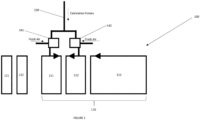
- FIG. 1 depicts a system 100 in accordance with the present invention.
- the system comprises a longitudinal dryer 110 comprising a first dryer zone 111, a second dryer zone 112, and a third dryer zone 113.
- hot air circulates in alternating directions in the first dryer zone 111 compared to the second dryer zone 112 and the third dryer zone 113 as indicated by the arrows in Figure 1 .
- the system 100 additionally comprises a first preheater 121 and a second preheater 122.
- the preheaters are located upstream of the first dryer zone 111, second dryer zone 112 and third dryer zone 113, such that a product to be dried, typically a gypsum board, first travels through the preheaters 121, 122 before travelling through the dryer 110.
- the temperature in the first preheater 121 is maintained between 50°C to 150°C
- the temperature in the second preheater 122 is maintained between 50°C to 150°C
- the temperature in the first dryer zone 111 is maintained between 200°C to 330°C
- the temperature in the second dryer zone 112 is maintained between 200°C to 330°C
- the temperature in the third dryer zone 113 is maintained between 200°C to 330°C.
- the temperature in the preheaters 121, 122 and the dryer 110 is maintained above the ambient.
- the temperature in the first dryer zone 111 and the second dryer zone 112 is maintained, in use, with the assistance of calcination fumes introduced into these zones via a calcination exhaust 130.
- the system 100 includes a calciner (not shown) that can be used to dehydrate gypsum at an elevated temperature.
- the calcination fumes in the calciner exhaust 130 are at an elevated temperature, often in the range of 130°C to 170°C, and can therefore be used to maintain an above ambient temperature within the first dryer zone 111 and the second dryer zone 112.
- the calcination exhaust 130 is fluidly connected to the first dryer zone 11 and the second dryer zone 112, such that the calcination fumes enter the zones to increase their temperature in a form of direct heating. In this way, the energy efficiency of the system 100 may be increased.
- the calcination fumes have a high humidity, frequently in the range of 50 g/kg to 1000 g/kg.
- the main aim of the dryer 100 is to dry the gypsum product in a controlled manner to ensure a consistent final product.
- controlling the humidity within the zones is also of significant importance.
- the system 100 of Figure 1 also includes a first mixing zone 141 and a second mixing zone 142, where the calcination fumes provided within the calciner exhaust 130 are mixed with additional air.
- the temperature and humidity of the air entering the first dryer zone 111 and second dryer zone 112 can be independently controlled via adjusting the ratio of calcination fumes to additional air introduced into the zones.
- the mixing zones are located outside of the first dryer zone 111 and the second dryer zone 112, it is also envisaged that the mixing zones may be with the dryer zones and the calcination fumes and additional air introduced into the dryer zones via separate inlets.
- Figure 2 illustrates a second system 200 in accordance with the present invention.
- the system 200 of Figure 2 includes all the same features as the system 100 of Figure 1 , each of these features numbered with equivalent reference numerals.
- the system 200 of Figure 2 additionally includes a dryer exhaust 250 extending from the third dryer zone 213. Whilst in Figure 2 the dryer exhaust is seen extending from the third dryer zone 213, it is envisaged that the dryer exhaust may extend from any one or more of the dryer zones.
- the dryer exhaust 250 carries air from the third dryer zone 213, this air being at a temperature above the ambient.
- the dryer exhaust 250 carries this air to a heat exchanger 260, where heat from the air in the dryer exhaust 250 is transferred to the additional air that will be mixed with the calcination fumes and introduced into the dryer 200, here to the first dryer zone 211 and the second dryer zone 212.
- waste heat in the air within the dryer exhaust 250 is used to preheat the additional air before it is mixed with the calcination fumes.
- a heat exchanger is used in the present embodiment, a heat pump would be appreciated as an alternative.
- Figure 3 illustrates a third system 300 in accordance with the present invention.
- the system 300 of Figure 3 includes all the same features as the system 200 of Figure 2 , each of these features numbered with equivalent reference numerals.
- the system 300 of Figure 3 additionally includes a dryer zone exhaust 370, the dryer zone exhaust transferring air from the first dryer zone 311 and the second dryer zone 312 to the third dryer zone 313. Whilst in Figure 3 the dryer zone exhaust extends from both the first 311 and second 312 dryer zones, it is also envisaged that it may extend from only one of the same. As the first dryer zone 311 and the second dryer zone are above the temperature of the third dryer zone 313, the dryer zone exhaust may be used to maintain the temperature of the third dryer zone 313 whilst reducing the energy usage of the system 300 as a whole.
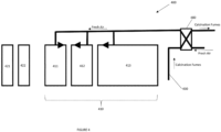
- Figure 4 illustrates a fourth system 400 in accordance with the present invention.
- the system 400 of Figure 4 includes a number of features identical to those previously described and, where this is the case, these features are numbered with equivalent reference numerals.
- the system 400 of Figure 4 uses the calcination fumes carried in the calciner exhaust 430 to indirectly heat the first dryer zone 411, second dryer zone 412 and third dryer zone 413.
- the calciner exhaust is fluidly connected to both the calciner (not shown) and a heat exchanger 480 where heat energy from the calcination fumes is transferred to additional air to be introduced into the dryer zones 411, 412, 413. In this way, heat energy wastage is reduced by the system 400, increasing its efficiency. Additionally, as the calcination fumes do not directly enter the dryer zones 411, 412, 413, conditions within the dryer zones in terms of humidity and temperature may be more easily controlled in the system of Figure 4 .
- system 400 of Figure 4 may additionally include a dryer zone exhaust as described in relation to Figure 3 .
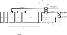
- Figure 5 illustrates a fifth system 500 in accordance with the present invention.
- the system 500 of Figure 5 includes all the same features as the system 400 of Figure 4 , each of these features numbered with equivalent reference numerals.
- the system 500 of Figure 5 additionally includes a dryer exhaust 550 extending from the third dryer zone 513. Whilst in Figure 5 the dryer exhaust is seen extending from the third dryer zone 513, it is envisaged that the dryer exhaust may extend from any one or more of the dryer zones.
- the dryer exhaust 550 carries air from the third dryer zone 513, this air being at a temperature above the ambient.
- the dryer exhaust 550 carries this air to a heat exchanger 590, where heat from the air in the dryer exhaust 550 is transferred to the additional air entering the dryer 510.
- the additional air entering the dryer zones 511, 512, 513 is heated by two heat exchangers 590, 580 in series.
- the additional air is heated in a heat exchanger 590 using otherwise waste energy in the air within the dryer exhaust 550, before the additional air is heated again in the heat exchanger 580 using otherwise waste energy in the calcination fumes in the calciner exhaust 530.
- system 500 of Figure 5 may additionally include a dryer zone exhaust as described in relation to Figure 3 .
- FIG. 6 depicts a thermal fluid loop 1000 that may be used in a system according to the present invention. Whilst individual heat exchangers can be used to transfer heat between the various fluid flows described in the previous embodiments, a thermal fluid loop 1000 can also be used.
- heat energy from the calcination fumes within the calciner exhaust 1030 can be transferred to a thermal fluid within the thermal fluid loop 1000 in a first heat exchanger 1100. This thermal energy in the thermal fluid is then transferred to the additional air that will be introduced into the dryer zones in a second heat exchanger 1150.
- the use of a thermal fluid loop may facilitate the installation of systems according to the present invention where the calciner is remote from the dryer.
- the at least one dryer zone may comprise a preheater and the system may be configured to use the heat energy from the calcination fumes to heat the preheaters.
Landscapes
- Engineering & Computer Science (AREA)
- Chemical & Material Sciences (AREA)
- Mechanical Engineering (AREA)
- General Engineering & Computer Science (AREA)
- Ceramic Engineering (AREA)
- Life Sciences & Earth Sciences (AREA)
- Sustainable Development (AREA)
- Materials Engineering (AREA)
- Structural Engineering (AREA)
- Organic Chemistry (AREA)
- Drying Of Solid Materials (AREA)
Abstract
A system for use in the production of a gypsum product is described, the system comprising a calciner for calcining gypsum; the calciner comprising at least one calciner exhaust; and a dryer comprising at least one dryer zone. The system is configured such that, in use, heat energy from calcination fumes within the at least one calciner exhaust heats, directly or indirectly, the at least one dryer zone. A method for use in the production of a gypsum product is also described.
Description
- The present disclosure relates generally to systems and methods for use in the production of a gypsum product, and finds particular, although not exclusive, utility in providing systems and methods for the reuse of heat in calcination fumes in the drying process.
- Industrial drying processes, for example the drying of gypsum products require significant amounts of energy. Industrial dryers can be composed of multiple zones that are maintained at different temperatures depending on the needs of the process. Providing the energy required to maintain such industrial dryers at the required temperatures is expensive. Additionally, there is a significant, negative environmental impact associated with current production techniques due to the amount of energy consumed.
- Aspects of the present disclosure seek to provide systems and methods that alleviate these problems with prior known systems. In particular, aspects of the present disclosure seek to provide systems and methods for drying with increased energy efficiency.
- According to a first aspect of the present invention, there is provided a system for use in the production a gypsum product, the system comprising:
- a calciner for calcining gypsum; the calciner comprising at least one calciner exhaust; and
- a dryer comprising at least one dryer zone,
- wherein the system is configured such that, in use, heat energy from calcination fumes within the at least one calciner exhaust heats, directly or indirectly, the at least one dryer zone.
- When using a system of this form, heat energy from the calcination fumes that would usually be wasted can be used to partially, or fully, maintain a raised temperature in the at least one dryer zone to dry a gypsum product. In this way, the apparatus is more energy efficient than those of the prior art.
- Preferably, the gypsum product is a gypsum board. A gypsum board is a board comprising at least 50 wt.% calcium sulphate dihydrate, more preferably at least 80 wt.% calcium sulphate dihydrate. More preferably, the gypsum board may have one or more facer layers. Still more preferably, the facer layer may comprise a paper or other cellulose based product
- Preferably, the at least one dryer zone and the at least one calciner exhaust are fluidly connected. In this way, the calcination fumes within the calciner exhaust may directly heat the at least one dryer zone, as the calcination fumes can be directly introduced into the at least one dryer zone. Where heating is direct, this ensures the at least one dryer zone is heated efficiently by the calcination fumes within the calciner exhaust.
- Preferably, the system comprises at least one heat exchanger. Preferably, the system comprises at least one heat pump. Preferably, the system comprises at least one thermal fluid loop. The use of a thermal fluid loop may be preferable as it may increase the ease with which the system can be installed or retrofitted where the calciner is located in a position relatively remote for the dryer.
- Preferably, the at least one heat exchanger, heat pump or thermal fluid loop is configured such that, in use, heat energy is transferred from calcination fumes within the calciner exhaust to air entering the at least one dryer zone. The use of a heat exchanger, heat pump or thermal fluid loop may be preferable as the calcination fumes have a high level of humidity and/or may comprise undesirable contaminants. As such, the use of a heat exchanger, heat pump or thermal fluid loop may allow the environment within the dryer to be controlled more accurately and reliably during any production process using the system.
- Preferably, the system comprises at least one dryer exhaust. In use the at least one dryer exhaust removes hot air from the dryer during the manufacturing process. Preferably, the system is configured such that, in use, heat energy from hot air within the at least one dryer exhaust heats, directly or indirectly, the at least one dryer zone.
- Preferably, the at least one heat exchanger, heat pump or thermal fluid loop is configured such that, in use, heat energy is transferred from the air within the at least one dryer exhaust to the air entering the at least one dryer zone. In this way, the efficiency of the system can be further increased, as heat energy within the air exiting the system in the at least one dryer exhaust can be used to heat the air entering the at least one dryer zone. Alternatively, the system is configured such that the at least one dryer zone and the at least one dryer exhaust are fluidly connected.
- Preferably, the system comprises a plurality of heat exchangers, heat pumps and/or thermal fluid loops, wherein the system is configured such that, in use, the air entering the at least one dryer zone is heated by air exiting the system in the dryer exhaust via a first heat exchanger, heat pump or thermal fluid system then heated in a second heat exchanger, heat pump or thermal fluid system by calcination fumes in the calciner exhaust. In this way, the efficiency of the system is once again increased.
- Preferably, the system is configured, in use, to mix the calcination fumes with additional air. In this way, the temperature and/or humidity level of the calcination fumes can be controlled, moderated or adjusted before the calcination fumes are used to heat the at least one dryer zone. Such a feature may assist in increasing the reliability of the system, for example by reducing the risk of corrosion in key areas or be enabling additional control of the conditions within the at least one dryer zone where the calcination fumes are introduced there directly.
- Preferably, the system is configured, in use, to mix the calcination fumes and additional air before the mixture is introduced to the at least one dryer zone. Such a feature may be advantageous in ensuring consistent conditions throughout a dryer zone. Alternatively, the system is configured, in use, to mix the calcination fumes and additional air within the at least one dryer zone. Such a feature may be advantageous as it can be more easily installed.
- Preferably, the dryer comprises a plurality of dryer zones. More preferably the dryer comprises a first dryer zone, a second dryer zone and a third dryer zone. In such embodiments, a gypsum product would move through the first zone, the second zone, then the third zone during the production process. Preferably, in use, the first dryer zone and the second dryer zone are maintained at a higher temperature than the third dryer zone. Preferably, the first dryer zone and the second dryer zone are maintained at a higher humidity than the third dryer zone.
- Preferably, during use, the first dryer zone is maintained at a temperature in the range of 200°C to 330°C inclusive. Preferably, during use, the first dryer zone is maintained at a humidity in the range of 100 g/kg to 600 g/kg inclusive.
- Preferably, during use, the second dryer zone is maintained at a temperature in the range of 200°C to 330°C inclusive. Preferably, during use, the second dryer zone is maintained at a humidity in the range of 100 g/kg to 600 g/kg inclusive.
- Preferably, during use, the third dryer zone is maintained at a temperature in the range of 100°C to 200°C inclusive. Preferably, during use, the third dryer zone is maintained at a humidity in the range of 20 g/kg to 500 g/kg inclusive.
- Preferably, the at least one dryer zone comprises at least one dryer zone exhaust, wherein in use, the at least one dryer zone exhaust transfers heat energy from one dryer zone to another dryer zone. Preferably, the at least one dryer zone exhaust transfers air directly from one dryer zone to another. More preferably, the at least one dryer zone exhaust transfers heat energy from the first dryer zone and/or the second dryer zone to the third dryer zone.
- Preferably, the at least one dryer zone comprises at least one preheater. More preferably, the at least one dryer zone comprises a plurality of preheaters. Still more preferably, the at least one dryer zone comprises a first preheater and a second preheater. Preferably, the first preheater is maintained at a temperature between 50°C to 150°C inclusive. Preferably, the second preheater is maintained at a temperature between 50°C to 150°C inclusive. Preferably, the first preheater is maintained at a humidity between 5 g/kg to 100 g/kg inclusive. Preferably, the second preheater is maintained at a humidity between 5 g/kg to 100 g/kg inclusive.
- Preferably, the at least one preheater comprises at least one preheater exhaust. In use the at least one preheater exhaust removes hot air from the preheater during the manufacturing process. Preferably, the system is configured such that, in use, heat energy from hot air within the at least one preheater exhaust heats, directly or indirectly, the at least one dryer zone.
- Preferably, the at least one heat exchanger, heat pump or thermal fluid loop is configured such that, in use, heat energy is transferred from the air within the at least one preheater exhaust to the air entering the at least one dryer zone. In this way, the efficiency of the system can be further increased, as heat energy within the air exiting the system in the at least one preheater exhaust can be used to heat the air entering the at least one dryer zone.
- Preferably, the additional air is ambient, untreated air. More preferably, the system is configured to filter the additional air.
- In some embodiments, the dryer is a longitudinal dryer. In some embodiments, the dryer is a transverse dryer. In some embodiments, the dryer is a jet dryer. Preferably the dryer is a longitudinal dryer.
- Preferably, the system comprises a heater. Preferably, the heater is a gas burner. Alternatively the heater is a resistance heater. Preferably, the system is configured such the heater directly or indirectly heats at least one of the dryer zones. More preferably, the system may be configures such that supplemental air is heated via the heater, then that supplemental air is introduced into at least one of the dryer zones. In this way, the temperature of each zone can be controlled more accurately and/or increased if required.
- Preferably, the method comprises directly or indirectly heating the at least one dryer zone with the heater. For example, the method may comprise heating supplemental air via the heater, then introducing this supplemental air into the at least one dryer zone.
- According to a second aspect of the present invention, there is provided a method for use in the production of a gypsum product, the method comprising:
- providing a calciner with at least one calciner exhaust;
- providing a dryer with at least one dryer zone
- calcining gypsum in the calciner; and
- utilising heat energy from calcination fumes within the calciner exhaust to heat, directly or indirectly, the at least one dryer zone.
- In this way, a method with the advantages hereinbefore described is provided. Preferably, the method comprises providing the apparatus as hereinbefore described. Preferably, the method is a method of manufacturing a gypsum board.
- Preferably, the calcination fumes in the calciner exhaust have a temperature of 130°C to 170°C inclusive.
- Preferably, the method comprises fluidly connecting the at least one dryer zone and the at least one calciner exhaust. In this way, the calcination fumes within the calciner exhaust may directly heat the at least one dryer zone, as the calcination fumes can be directly introduced into the at least one dryer zone. Where heating is direct, this ensures the at least one dryer zone is heated efficiently by the calcination fumes within the calciner exhaust.
- Preferably, the method comprises providing at least one heat exchanger. Preferably, the method comprises providing at least one heat pump. Preferably, the method comprises providing at least one thermal fluid loop. Preferably, the method comprises transferring heat energy from calcination fumes within the calciner exhaust to air entering the at least one dryer zone via the at least one heat exchanger, heat pump or thermal fluid loop.
- Preferably, the method comprises providing at least one dryer exhaust to remove hot air from the dryer during the manufacturing process. Preferably, the method comprises transferring heat energy from hot air within the at least one dryer exhaust, directly or indirectly, to the at least one dryer zone.
- Preferably, the method comprises transferring heat energy from the air within the at least one dryer exhaust to the air entering the at least one dryer zone via at least one heat exchanger, heat pump or thermal fluid loop. Alternatively, the method comprises fluidly connecting the at least one dryer zone and the at least one dryer exhaust.
- Preferably, the method comprises providing a plurality of heat exchangers, heat pumps and/or thermal fluid loops, wherein the air entering the at least one dryer zone is heated by air exiting the system in the dryer exhaust via a first heat exchanger, heat pump or thermal fluid system then heated in a second heat exchanger, heat pump or thermal fluid system by calcination fumes in the calciner exhaust.
- Preferably, the method further comprises mixing the calcination fumes with additional air. More preferably, the calcination fumes and additional air are mixed before the mixture is introduced to the at least one dryer zone. Alternatively, the calcination fumes and additional air are mixed within the at least one dryer zone
- Preferably, the method comprises maintaining the temperature in the at least one dryer zone between 100°C and 330°C. Preferably, wherein the method comprises maintaining the humidity in the at least one dryer zone between 10 g/kg and 600 g/kg.
- Preferably, the method comprises providing a dryer with a plurality of dryer zones. More preferably, the method comprises maintaining each dryer zone at a different temperature and or humidity.
- Preferably, the method comprises providing a dryer with a first dryer zone, a second dryer zone and a third dryer zone. In such embodiments, a gypsum product would move through the first zone, the second zone, then the third zone during the production process. Preferably, the method comprises maintaining the first dryer zone and/or the second dryer zone at a higher temperature than the third dryer zone. Preferably, the method comprises maintaining the first dryer zone and/or the second dryer zone at a higher humidity than the third dryer zone.
- Preferably, the method comprises maintaining the first dryer zone at a temperature in the range of 200°C to 330°C inclusive. Preferably, the method comprises maintaining the first dryer zone at a humidity in the range of 100 g/kg to 600 g/kg inclusive.
- Preferably, the method comprises maintaining the second dryer zone at a temperature in the range of 200°C to 330°C inclusive. Preferably, the method comprises maintaining the second dryer zone at a humidity in the range of 100 g/kg to 600 g/kg inclusive.
- Preferably, the method comprises maintaining the third dryer zone at a temperature in the range of 100°C to 200°C inclusive. Preferably, the method comprises maintaining the third dryer zone at a humidity in the range of 20 g/kg to 500 g/kg inclusive.
- Preferably, the method comprises providing at least one dryer zone exhaust. Here the method may comprise transferring heat energy from one dryer zone to another using the at least one dryer zone exhaust. More preferably, this heat transfer is direct.
- Preferably, the at least one dryer zone exhaust transfers heat energy from a one dryer zone to another dryer zone. Preferably, the at least one dryer zone exhaust transfers air directly from one dryer zone to another. More preferably, the method comprises using the dryer zone exhaust to transfer heat energy from the first dryer zone and/or the second dryer zone to the third dryer zone.
- Preferably, the at least one dryer zone comprises at least one preheater. More preferably, the at least one dryer zone comprises a plurality of preheaters. Still more preferably, the at least one dryer zone comprises a first preheater and a second preheater. Preferably, the method comprises maintaining the first preheater at a temperature between 50°C to 150°C inclusive. Preferably, the method comprises maintaining the second preheater at a temperature between 50°C to 150° inclusive. Preferably, the method comprises maintaining the first preheater at a humidity between 5 g/kg to 100 g/kg inclusive. Preferably, the method comprises maintaining the second preheater at a humidity between 5 g/kg to 100 g/kg inclusive.
- Preferably, the method comprises providing at least one preheater exhaust. Preferably, the method comprises removing hot air from the preheater via the preheater exhaust. Preferably, the method comprises transferring heat energy from hot air within the at least one preheater exhaust, directly or indirectly, to the at least one dryer zone.
- Preferably, the method comprises transferring heat energy from the air within the at least one preheater exhaust to the air entering the at least one dryer zone via at least one heat exchanger, heat pump or thermal fluid loop.
- Preferably, the method comprises providing a heater. Preferably, the heater is a gas burner. Alternatively, the heater is a resistance heater. Preferably, the method comprises directly or indirectly heating at least one of the dryer zones with the heater. For example, the method may comprise heating supplemental air via the heater, then introducing this supplemental air into at least one of the dryer zones.
- The disclosure will be further described with reference to examples depicted in the accompanying figures in which:
-
Figure 1 is a schematic diagram showing a first embodiment of the present invention; -
Figure 2 is a schematic diagram showing a second embodiment of the present invention; -
Figure 3 is a schematic diagram showing a third embodiment of the present invention; -
Figure 4 is a schematic diagram showing a fourth embodiment of the present invention; -
Figure 5 is a schematic diagram showing a fifth embodiment of the present invention; and -
Figure 6 is a schematic diagram showing a thermal fluid loop for use in embodiments of the present invention. - The following description presents particular examples and, together with the drawings, serves to explain principles of the disclosure. However, the scope of the invention is not intended to be limited to the precise details of the examples, since variations will be apparent to a skilled person and are deemed to be covered by the description. Terms for components used herein should be given a broad interpretation that also encompasses equivalent functions and features. In some cases, alternative terms for structural features may be provided but such terms are not intended to be exhaustive.
- Descriptive terms should also be given the broadest possible interpretation; e.g. the term "comprising" as used in this specification means "consisting at least in part of' such that interpreting each statement in this specification that includes the term "comprising", features other than that or those prefaced by the term may also be present. Related terms such as "comprise" and "comprises" are to be interpreted in the same manner.
- The description herein refers to examples with particular combinations of features, however, it is envisaged that further combinations and cross-combinations of compatible features between embodiments will be possible. Indeed, isolated features may function independently as an invention from other features and not necessarily require implementation as a complete combination.
- Figure depicts a
system 100 in accordance with the present invention. The system comprises alongitudinal dryer 110 comprising afirst dryer zone 111, asecond dryer zone 112, and athird dryer zone 113. During use, hot air circulates in alternating directions in thefirst dryer zone 111 compared to thesecond dryer zone 112 and thethird dryer zone 113 as indicated by the arrows inFigure 1 . - The
system 100 additionally comprises afirst preheater 121 and asecond preheater 122. The preheaters are located upstream of thefirst dryer zone 111,second dryer zone 112 andthird dryer zone 113, such that a product to be dried, typically a gypsum board, first travels through thepreheaters dryer 110. In use, the temperature in thefirst preheater 121 is maintained between 50°C to 150°C, the temperature in thesecond preheater 122 is maintained between 50°C to 150°C, the temperature in thefirst dryer zone 111 is maintained between 200°C to 330°C, the temperature in thesecond dryer zone 112 is maintained between 200°C to 330°C, and the temperature in thethird dryer zone 113 is maintained between 200°C to 330°C. - As such, in use, the temperature in the
preheaters dryer 110 is maintained above the ambient. In the embodiment ofFigure 1 , the temperature in thefirst dryer zone 111 and thesecond dryer zone 112 is maintained, in use, with the assistance of calcination fumes introduced into these zones via acalcination exhaust 130. Thesystem 100 includes a calciner (not shown) that can be used to dehydrate gypsum at an elevated temperature. As calcination is conducted at an elevated temperature, the calcination fumes in thecalciner exhaust 130 are at an elevated temperature, often in the range of 130°C to 170°C, and can therefore be used to maintain an above ambient temperature within thefirst dryer zone 111 and thesecond dryer zone 112. In the embodiment ofFigure 1 , thecalcination exhaust 130 is fluidly connected to the first dryer zone 11 and thesecond dryer zone 112, such that the calcination fumes enter the zones to increase their temperature in a form of direct heating. In this way, the energy efficiency of thesystem 100 may be increased. - As well as an elevated temperature, the calcination fumes have a high humidity, frequently in the range of 50 g/kg to 1000 g/kg. The main aim of the
dryer 100 is to dry the gypsum product in a controlled manner to ensure a consistent final product. As such as well as the temperature of the dryer zones, controlling the humidity within the zones is also of significant importance. As such, thesystem 100 ofFigure 1 also includes afirst mixing zone 141 and asecond mixing zone 142, where the calcination fumes provided within thecalciner exhaust 130 are mixed with additional air. As such, the temperature and humidity of the air entering thefirst dryer zone 111 andsecond dryer zone 112 can be independently controlled via adjusting the ratio of calcination fumes to additional air introduced into the zones. Whilst in the embodiment depicted inFigure 1 the mixing zones are located outside of thefirst dryer zone 111 and thesecond dryer zone 112, it is also envisaged that the mixing zones may be with the dryer zones and the calcination fumes and additional air introduced into the dryer zones via separate inlets. -
Figure 2 illustrates asecond system 200 in accordance with the present invention. Thesystem 200 ofFigure 2 includes all the same features as thesystem 100 ofFigure 1 , each of these features numbered with equivalent reference numerals. - The
system 200 ofFigure 2 additionally includes adryer exhaust 250 extending from thethird dryer zone 213. Whilst inFigure 2 the dryer exhaust is seen extending from thethird dryer zone 213, it is envisaged that the dryer exhaust may extend from any one or more of the dryer zones. Here, thedryer exhaust 250 carries air from thethird dryer zone 213, this air being at a temperature above the ambient. Thedryer exhaust 250 carries this air to aheat exchanger 260, where heat from the air in thedryer exhaust 250 is transferred to the additional air that will be mixed with the calcination fumes and introduced into thedryer 200, here to thefirst dryer zone 211 and thesecond dryer zone 212. As such, there is a further increase in efficiency, as waste heat in the air within thedryer exhaust 250 is used to preheat the additional air before it is mixed with the calcination fumes. Whilst a heat exchanger is used in the present embodiment, a heat pump would be appreciated as an alternative. -
Figure 3 illustrates athird system 300 in accordance with the present invention. Thesystem 300 ofFigure 3 includes all the same features as thesystem 200 ofFigure 2 , each of these features numbered with equivalent reference numerals. - The
system 300 ofFigure 3 additionally includes adryer zone exhaust 370, the dryer zone exhaust transferring air from thefirst dryer zone 311 and thesecond dryer zone 312 to thethird dryer zone 313. Whilst inFigure 3 the dryer zone exhaust extends from both the first 311 and second 312 dryer zones, it is also envisaged that it may extend from only one of the same. As thefirst dryer zone 311 and the second dryer zone are above the temperature of thethird dryer zone 313, the dryer zone exhaust may be used to maintain the temperature of thethird dryer zone 313 whilst reducing the energy usage of thesystem 300 as a whole. -
Figure 4 illustrates afourth system 400 in accordance with the present invention. Thesystem 400 ofFigure 4 includes a number of features identical to those previously described and, where this is the case, these features are numbered with equivalent reference numerals. - The
system 400 ofFigure 4 uses the calcination fumes carried in thecalciner exhaust 430 to indirectly heat thefirst dryer zone 411,second dryer zone 412 andthird dryer zone 413. - The calciner exhaust is fluidly connected to both the calciner (not shown) and a
heat exchanger 480 where heat energy from the calcination fumes is transferred to additional air to be introduced into thedryer zones system 400, increasing its efficiency. Additionally, as the calcination fumes do not directly enter thedryer zones Figure 4 . - Whilst not shown, it is also envisaged that the
system 400 ofFigure 4 may additionally include a dryer zone exhaust as described in relation toFigure 3 . -
Figure 5 illustrates afifth system 500 in accordance with the present invention. Thesystem 500 ofFigure 5 includes all the same features as thesystem 400 ofFigure 4 , each of these features numbered with equivalent reference numerals. - The
system 500 ofFigure 5 additionally includes adryer exhaust 550 extending from thethird dryer zone 513. Whilst inFigure 5 the dryer exhaust is seen extending from thethird dryer zone 513, it is envisaged that the dryer exhaust may extend from any one or more of the dryer zones. Here, thedryer exhaust 550 carries air from thethird dryer zone 513, this air being at a temperature above the ambient. Thedryer exhaust 550 carries this air to aheat exchanger 590, where heat from the air in thedryer exhaust 550 is transferred to the additional air entering thedryer 510. In thesystem 500 ofFigure 5 , the additional air entering thedryer zones heat exchangers heat exchanger 590 using otherwise waste energy in the air within thedryer exhaust 550, before the additional air is heated again in theheat exchanger 580 using otherwise waste energy in the calcination fumes in thecalciner exhaust 530. - Whilst not shown, it is also envisaged that the
system 500 ofFigure 5 may additionally include a dryer zone exhaust as described in relation toFigure 3 . -
Figure 6 depicts athermal fluid loop 1000 that may be used in a system according to the present invention. Whilst individual heat exchangers can be used to transfer heat between the various fluid flows described in the previous embodiments, athermal fluid loop 1000 can also be used. InFigure 6 , heat energy from the calcination fumes within thecalciner exhaust 1030 can be transferred to a thermal fluid within thethermal fluid loop 1000 in afirst heat exchanger 1100. This thermal energy in the thermal fluid is then transferred to the additional air that will be introduced into the dryer zones in asecond heat exchanger 1150. The use of a thermal fluid loop may facilitate the installation of systems according to the present invention where the calciner is remote from the dryer. - The invention is not limited to the specific examples or structures illustrated. For example, the at least one dryer zone may comprise a preheater and the system may be configured to use the heat energy from the calcination fumes to heat the preheaters.
Claims (15)
- A system for use in the production of a gypsum product, the system comprising:a calciner for calcining gypsum; the calciner comprising at least one calciner exhaust; anda dryer comprising at least one dryer zone,wherein the system is configured such that, in use, heat energy from calcination fumes within the at least one calciner exhaust heats, directly or indirectly, the at least one dryer zone.
- The system of claim 1, wherein the at least one dryer zone and the at least one calciner exhaust are fluidly connected.
- The system of claim 1 or claim 2, wherein the system comprises at least one heat exchanger or thermal fluid loop.
- The system of claim 3, wherein the at least one heat exchanger or thermal fluid loop is configured such that, in use, heat energy is transferred from calcination fumes within the calciner exhaust to air entering the at least one dryer zone.
- The system of claim 3 or claim 4, wherein the system comprises a dryer exhaust, and the at least one heat exchanger or thermal fluid loop is configured such that, in use, heat energy is transferred from the air within the dryer exhaust to the air entering the at least one dryer zone.
- The system of any one preceding claim, wherein the system is configured, in use to mix the calcination fumes with additional air.
- The system of claim 6, wherein the system is configured, in use, to mix the calcination fumes and additional air before the mixture is introduced to the at least one dryer zone.
- The system of claim 6, wherein the system is configured, in use, to mix the calcination fumes and additional air within the at least one dryer zone.
- The system of any one preceding claim, wherein the dryer comprises a plurality of dryer zones.
- The system of claim 9, wherein at least one dryer zone comprises at least one dryer zone exhaust, wherein in use, the at least one dryer zone exhaust transfers heat energy from a one dryer zone to another dryer zone.
- A method for use in the production of a gypsum product, the method comprising:providing a calciner with at least one calciner exhaust;providing a dryer with at least one dryer zonecalcining gypsum in the calciner; andutilising heat energy from calcination fumes within the calciner exhaust to heat,directly or indirectly, the at least one dryer zone.
- The method of claim 11, wherein the method further comprises mixing the calcination fumes with additional air.
- The method of claim 11 or claim 12, wherein the method comprises maintaining the temperature in the at least one dryer zone between 100°C and 330°C.
- The method of any one of claims 11 to 13, wherein the method comprises maintaining the humidity in the at least one dryer zone between 10 g/kg and 600 g/kg.
- The method of any one of claims 11 to 14, wherein the method comprises providing a dryer with a plurality of dryer zones, and further comprises maintaining each dryer zone at a different temperature and or humidity.
Priority Applications (2)
| Application Number | Priority Date | Filing Date | Title |
|---|---|---|---|
| EP23306621.6A EP4530564A1 (en) | 2023-09-27 | 2023-09-27 | Systems and methods for use in the production of a gypsum product |
| PCT/EP2024/074085 WO2025067805A1 (en) | 2023-09-27 | 2024-08-28 | Systems and methods for use in the production of a gypsum product |
Applications Claiming Priority (1)
| Application Number | Priority Date | Filing Date | Title |
|---|---|---|---|
| EP23306621.6A EP4530564A1 (en) | 2023-09-27 | 2023-09-27 | Systems and methods for use in the production of a gypsum product |
Publications (1)
| Publication Number | Publication Date |
|---|---|
| EP4530564A1 true EP4530564A1 (en) | 2025-04-02 |
Family
ID=88316011
Family Applications (1)
| Application Number | Title | Priority Date | Filing Date |
|---|---|---|---|
| EP23306621.6A Pending EP4530564A1 (en) | 2023-09-27 | 2023-09-27 | Systems and methods for use in the production of a gypsum product |
Country Status (2)
| Country | Link |
|---|---|
| EP (1) | EP4530564A1 (en) |
| WO (1) | WO2025067805A1 (en) |
Citations (5)
| Publication number | Priority date | Publication date | Assignee | Title |
|---|---|---|---|---|
| US20090217546A1 (en) * | 2007-11-30 | 2009-09-03 | John College | Method for the Use of Heat Energy From Gasification Sources in Gypsum Board Production |
| CN207451624U (en) * | 2017-11-21 | 2018-06-05 | 宜昌鄂中化工有限公司 | A kind of acid production with sulphur waste heat is used for the device of ardealite comprehensive utilization |
| EP3717851B1 (en) * | 2017-11-28 | 2022-03-16 | Etex Building Performance International SAS | Sheet drying method and arrangement |
| EP4033187A1 (en) * | 2021-01-20 | 2022-07-27 | Saint-Gobain Placo | Industrial drying apparatus |
| CN217236284U (en) * | 2022-03-16 | 2022-08-19 | 青岛理工瑞达节能环保科技有限公司 | A gypsum building material drying device |
Family Cites Families (1)
| Publication number | Priority date | Publication date | Assignee | Title |
|---|---|---|---|---|
| NL8003237A (en) * | 1980-06-03 | 1982-01-04 | Norgips Bv | METHOD AND INSTALLATION FOR MANUFACTURING PLASTER PRODUCTS |
-
2023
- 2023-09-27 EP EP23306621.6A patent/EP4530564A1/en active Pending
-
2024
- 2024-08-28 WO PCT/EP2024/074085 patent/WO2025067805A1/en active Pending
Patent Citations (5)
| Publication number | Priority date | Publication date | Assignee | Title |
|---|---|---|---|---|
| US20090217546A1 (en) * | 2007-11-30 | 2009-09-03 | John College | Method for the Use of Heat Energy From Gasification Sources in Gypsum Board Production |
| CN207451624U (en) * | 2017-11-21 | 2018-06-05 | 宜昌鄂中化工有限公司 | A kind of acid production with sulphur waste heat is used for the device of ardealite comprehensive utilization |
| EP3717851B1 (en) * | 2017-11-28 | 2022-03-16 | Etex Building Performance International SAS | Sheet drying method and arrangement |
| EP4033187A1 (en) * | 2021-01-20 | 2022-07-27 | Saint-Gobain Placo | Industrial drying apparatus |
| CN217236284U (en) * | 2022-03-16 | 2022-08-19 | 青岛理工瑞达节能环保科技有限公司 | A gypsum building material drying device |
Also Published As
| Publication number | Publication date |
|---|---|
| WO2025067805A1 (en) | 2025-04-03 |
Similar Documents
| Publication | Publication Date | Title |
|---|---|---|
| EP3717851B1 (en) | Sheet drying method and arrangement | |
| AU2007314134B2 (en) | Method for alumina production | |
| US9873635B2 (en) | Method and device for producing cement clinker | |
| AU2016287352B2 (en) | Process for production of sulfuric acid | |
| US20120247371A1 (en) | Method and installation for producing cement clinker | |
| CN107421297A (en) | Drying unit and the dryer with the improved device for being used for heat input for textile fabric breadth | |
| AT522579B1 (en) | PLANT FOR BURNING CERAMIC GOODS BLANKS | |
| CN102401554A (en) | Drying system for gypsum board | |
| CN101703995B (en) | Drying device for coating compound machine | |
| RU2015148947A (en) | METHOD AND DEVICE FOR PRODUCTION OF CEMENT CLINKER | |
| US4238187A (en) | Waste heat recovery system | |
| WO2025067805A1 (en) | Systems and methods for use in the production of a gypsum product | |
| CN103968410B (en) | A kind of low-temperature flue gas and the residual neat recovering system of flash-off steam | |
| US20240077254A1 (en) | Apparatus for Drying Gypsum Boards | |
| TW200907041A (en) | Method and apparatus for carbonization treatment of highly hydrous organic matter | |
| CN207451624U (en) | A kind of acid production with sulphur waste heat is used for the device of ardealite comprehensive utilization | |
| CN114804682A (en) | Energy-concerving and environment-protective system of calcining of gypsum | |
| CN103241717B (en) | Drying and calcining process and device for coproduction of sulfuric acid and cement from gypsum | |
| CN203771906U (en) | Device for drying ammonium sulfate by recycling flue gas generated from crude benzene production | |
| EA016569B1 (en) | Process and plant for the thermal treatment of granular solids | |
| WO2025247560A1 (en) | A drying system and method | |
| CN106903991B (en) | Air circulation system for multi-color printing press | |
| JP2024503184A (en) | industrial calcination equipment | |
| CN120225826A (en) | Method for producing binder using thermal energy and method for drying board produced using binder in drying apparatus | |
| CN102398303A (en) | Gypsum board production line |
Legal Events
| Date | Code | Title | Description |
|---|---|---|---|
| PUAI | Public reference made under article 153(3) epc to a published international application that has entered the european phase |
Free format text: ORIGINAL CODE: 0009012 |
|
| STAA | Information on the status of an ep patent application or granted ep patent |
Free format text: STATUS: THE APPLICATION HAS BEEN PUBLISHED |
|
| AK | Designated contracting states |
Kind code of ref document: A1 Designated state(s): AL AT BE BG CH CY CZ DE DK EE ES FI FR GB GR HR HU IE IS IT LI LT LU LV MC ME MK MT NL NO PL PT RO RS SE SI SK SM TR |
|
| STAA | Information on the status of an ep patent application or granted ep patent |
Free format text: STATUS: REQUEST FOR EXAMINATION WAS MADE |
|
| 17P | Request for examination filed |
Effective date: 20251001 |