EP4530553A1 - Non-metal liner and electric water heater having same - Google Patents
Non-metal liner and electric water heater having same Download PDFInfo
- Publication number
- EP4530553A1 EP4530553A1 EP22944652.1A EP22944652A EP4530553A1 EP 4530553 A1 EP4530553 A1 EP 4530553A1 EP 22944652 A EP22944652 A EP 22944652A EP 4530553 A1 EP4530553 A1 EP 4530553A1
- Authority
- EP
- European Patent Office
- Prior art keywords
- liner
- annular portion
- flange
- metal
- reinforcement layer
- Prior art date
- Legal status (The legal status is an assumption and is not a legal conclusion. Google has not performed a legal analysis and makes no representation as to the accuracy of the status listed.)
- Pending
Links
Images

Classifications
-
- F—MECHANICAL ENGINEERING; LIGHTING; HEATING; WEAPONS; BLASTING
- F24—HEATING; RANGES; VENTILATING
- F24H—FLUID HEATERS, e.g. WATER OR AIR HEATERS, HAVING HEAT-GENERATING MEANS, e.g. HEAT PUMPS, IN GENERAL
- F24H1/00—Water heaters, e.g. boilers, continuous-flow heaters or water-storage heaters
- F24H1/18—Water-storage heaters
- F24H1/181—Construction of the tank
Definitions
- the present application relates to the technical field of electric water heaters, for example, a non-metal liner and an electric water heater having the same.
- the liner of an electric water heater serving as a water storage component, is mostly made of metal.
- a heating pipe also needs to be installed in the liner.
- a liner flange is usually welded at the liner opening of the metal liner, and then the heating pipe is installed on the heating pipe flange.
- the liner flange and the heating pipe flange are fixedly connected to achieve the installation of the heating pipe in the metal liner.
- the liner flange is typically embedded at the liner opening of the non-metal liner through a welding process and then fixedly connected to a heating pipe flange.
- a fixing member with internal threads is molded in the liner opening of the non-metal liner, and the liner flange, which has external threads, is threadedly connected to the fixing member.
- the heating pipe flange which holds the heating pipe, is then connected to the liner flange.
- the disadvantages of this solution lie in the presence of multiple interfaces, such as between the fixing member and the liner flange and between the liner flange and the heating pipe flange.
- the high number of interfaces increases the likelihood of installation defects and raises the probability of water leakage, thereby affecting the performance of the electric water heater and in severe cases, even posing safety risks.
- the present application provides a non-metal liner and an electric water heater having the same.
- a non-metal liner includes a liner body, a reinforcement layer, and a liner flange.
- One end of the liner body forms a liner opening, and a limiting annular portion surrounding the liner opening is disposed on an outer side of the liner opening.
- the reinforcement layer covers an outer periphery of the liner body.
- An inner end of the liner flange is limited and fixed by the limiting annular portion, and an outer end of the liner flange is fixed between the liner body and the reinforcement layer.
- An electric water heater includes the non-metal liner as described above.
- connection to each other is to be construed in a broad sense, for example, as securely connected, detachably connected, or integrated; mechanically connected or electrically connected; directly connected to each other or indirectly connected to each other via an intermediary; or internally connected between two elements or interaction relations between two elements.
- connection detachably connected, or integrated; mechanically connected or electrically connected; directly connected to each other or indirectly connected to each other via an intermediary; or internally connected between two elements or interaction relations between two elements.
- first feature and the second feature may be in direct contact or be in contact via another feature between the two features instead of being in direct contact.
- first feature is "on”, “above”, or “over” the second feature
- first feature is right on, above, or over the second feature, or the first feature is obliquely on, above, or over the second feature, or the first feature is simply at a higher level than the second feature.
- the first feature When the first feature is “under”, “below”, or “underneath” the second feature, the first feature is right under, below, or underneath the second feature, or the first feature is obliquely under, below, or underneath the second feature, or the first feature is simply at a lower level than the second feature.
- orientations or position relations indicated by terms such as “above”, “below”, “left”, and “right” are based on orientations or position relations shown in the drawings. These orientations or position relations are intended only to facilitate and simplify the operation and not to indicate or imply that a device or element referred to must have such specific orientations or must be configured or operated in such specific orientations. Thus, these orientations or position relations are not to be construed as limiting the present application.
- terms “first” and “second” are used only to distinguish between descriptions and have no special meaning.
- the present application provides a non-metal liner.
- the non-metal liner is applied to the field of water heaters, such as electric water heaters and is configured to store water.
- the non-metal liner may be a plastic liner or a liner made of other non-metallic materials.
- the non-metal liner of the embodiments of the present application includes a liner body 10, a reinforcement layer 20, and a liner flange 30; one end of the liner body 10 forms a liner opening 11, and a limiting annular portion 12 surrounding the liner opening 11 is disposed on an outer side of the liner opening 11; the reinforcement layer 20 covers an outer periphery of the liner body 10; an inner end of the liner flange 30 is limited and fixed by the limiting annular portion 12, and an outer end of the liner flange 30 is fixed between the liner body 10 and the reinforcement layer 20.
- a limiting annular portion 12 surrounding the liner opening 11 is disposed on the outer side of the liner opening 11, the inner end of the liner flange 30 is limited and fixed by the limiting annular portion 12, and the outer end is fixed between the liner body 10 and the reinforcement layer 20.
- the liner flange 30 and the liner body 10 can be tightly combined, and no welding point exists, which avoids the leakage at the welded position when the non-metal liner is under high pressure.
- the liner flange 30 is directly connected to the liner body 10, eliminating the fixing members for fixing the liner flange 30 and reducing the connection interfaces between the fixing members and the liner flange 30, thereby reducing the probability of leakage.
- the limiting annular portion 12 may be formed integrally with the liner body 10 in the direction from the end of the liner opening 11 away from the center of the liner opening 11. Alternatively, the limiting annular portion 12 may be an independent component set on the outer side of the liner opening 11. The limiting annular portion 12 may be arranged as needed.
- the liner flange 30 includes an inner end annular portion 31, an outer end annular portion 33, and a protruded connecting portion 32 connected between the inner end annular portion 31 and the outer end annular portion 33, the inner end annular portion 31 is limited and fixed by the limiting annular portion 12, the outer end annular portion 33 is fixed between the liner body 10 and the reinforcement layer 20, and the protruded connecting portion 32 is configured to be connected to a heating pipe flange.
- the liner flange 30 is configured to include three parts, namely, the inner end annular portion 31, the protruded connecting portion 32, and the outer end annular portion 33 so that the connection between the liner flange 30 and the liner body 10 and between the liner flange 30 and the heating pipe flange is simpler, and the structure of the liner flange 30 is more reasonable.
Landscapes
- Engineering & Computer Science (AREA)
- Physics & Mathematics (AREA)
- Thermal Sciences (AREA)
- Chemical & Material Sciences (AREA)
- Combustion & Propulsion (AREA)
- Mechanical Engineering (AREA)
- General Engineering & Computer Science (AREA)
- Heat-Pump Type And Storage Water Heaters (AREA)
Abstract
Description
- This application claims priority to
Chinese Patent Application No. 202210624531.2 filed with the China National Intellectual Property Administration (CNIPA) on Jun. 02, 2022 Chinese Patent Application No. 202221387758.1 filed with the CNIPA on Jun. 02, 2022 - The present application relates to the technical field of electric water heaters, for example, a non-metal liner and an electric water heater having the same.
- The liner of an electric water heater, serving as a water storage component, is mostly made of metal. To heat the water in the metal liner, a heating pipe also needs to be installed in the liner. During the installation of the heating pipe, a liner flange is usually welded at the liner opening of the metal liner, and then the heating pipe is installed on the heating pipe flange. The liner flange and the heating pipe flange are fixedly connected to achieve the installation of the heating pipe in the metal liner.
- However, most liners are made of stainless steel or enamel. Although these types of liners can meet pressure requirements, they have several drawbacks, including low insulation coefficients, poor corrosion resistance, and high processing costs. Therefore, the market has begun using non-metal liners (such as plastic liners) to replace liners of stainless steel or enamel. However, this substitution introduces the following problems: To achieve a fixed connection with the heating pipe flange, it is still necessary to provide a liner flange at the liner opening of a non-metal liner.
- In related art, the liner flange is typically embedded at the liner opening of the non-metal liner through a welding process and then fixedly connected to a heating pipe flange. With this structure, when the non-metal liner is subjected to high pressure, cracks may develop at the welded position between the liner opening of the non-metal liner and the liner flange due to excessive pressure, leading to water leakage.
- To avoid welding between the liner flange and the non-metal liner, the related art often adopts the following solution: A fixing member with internal threads is molded in the liner opening of the non-metal liner, and the liner flange, which has external threads, is threadedly connected to the fixing member. The heating pipe flange, which holds the heating pipe, is then connected to the liner flange. The disadvantages of this solution lie in the presence of multiple interfaces, such as between the fixing member and the liner flange and between the liner flange and the heating pipe flange. Moreover, the high number of interfaces increases the likelihood of installation defects and raises the probability of water leakage, thereby affecting the performance of the electric water heater and in severe cases, even posing safety risks.
- The present application provides a non-metal liner and an electric water heater having the same.
- A non-metal liner includes a liner body, a reinforcement layer, and a liner flange.
- One end of the liner body forms a liner opening, and a limiting annular portion surrounding the liner opening is disposed on an outer side of the liner opening.
- The reinforcement layer covers an outer periphery of the liner body.
- An inner end of the liner flange is limited and fixed by the limiting annular portion, and an outer end of the liner flange is fixed between the liner body and the reinforcement layer.
- An electric water heater includes the non-metal liner as described above.
-
-
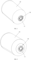
FIG. 1 is a view illustrating the structure of a non-metal liner according to an embodiment of the present application. -
FIG. 2 is a view illustrating the structure of a non-metal liner after removing the reinforcement layer according to an embodiment of the present application. -
FIG. 3 is a view illustrating the structure of a liner flange according to an embodiment of the present application. -
FIG. 4 is a sectional view of a liner flange according to an embodiment of the present application. -
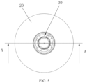
FIG. 5 is a front view of a non-metal liner according to the present application. -
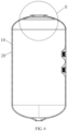
FIG. 6 is a sectional view taken along an A-A direction ofFIG. 5 . -
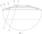
FIG. 7 is an enlarged view of point B inFIG. 6 . -
- 10
- liner body
- 11
- liner opening
- 12
- limiting annular portion
- 13
- thickened portion
- 20
- reinforcement layer
- 30
- liner flange
- 31
- inner end annular portion
- 32
- protruded connecting portion
- 33
- outer end annular portion
- The technical solutions of the present application are described hereinafter in conjunction with drawings and embodiments. Specific embodiments described herein are only intended to explain the present application. For ease of description, only the parts related to the present application are illustrated in the drawings.
- In the description of the present application, unless otherwise specified and limited, the term "connected to each other", "connected" or "secured" is to be construed in a broad sense, for example, as securely connected, detachably connected, or integrated; mechanically connected or electrically connected; directly connected to each other or indirectly connected to each other via an intermediary; or internally connected between two elements or interaction relations between two elements. For those of ordinary skill in the art, meanings of the preceding terms can be understood according to situations in the present application.
- In the present application, unless otherwise specified and limited, when a first feature is described as "on" or "below" a second feature, the first feature and the second feature may be in direct contact or be in contact via another feature between the two features instead of being in direct contact. Moreover, when the first feature is "on", "above", or "over" the second feature, the first feature is right on, above, or over the second feature, or the first feature is obliquely on, above, or over the second feature, or the first feature is simply at a higher level than the second feature. When the first feature is "under", "below", or "underneath" the second feature, the first feature is right under, below, or underneath the second feature, or the first feature is obliquely under, below, or underneath the second feature, or the first feature is simply at a lower level than the second feature.
- In the description of the present application, it should be noted that orientations or position relations indicated by terms such as "above", "below", "left", and "right" are based on orientations or position relations shown in the drawings. These orientations or position relations are intended only to facilitate and simplify the operation and not to indicate or imply that a device or element referred to must have such specific orientations or must be configured or operated in such specific orientations. Thus, these orientations or position relations are not to be construed as limiting the present application. In addition, terms "first" and "second" are used only to distinguish between descriptions and have no special meaning.
- The present application provides a non-metal liner. The non-metal liner is applied to the field of water heaters, such as electric water heaters and is configured to store water. In the embodiments, the non-metal liner may be a plastic liner or a liner made of other non-metallic materials.
- As shown in
FIGS. 1 to 7 , the non-metal liner of the embodiments of the present application includes aliner body 10, areinforcement layer 20, and aliner flange 30; one end of theliner body 10 forms aliner opening 11, and a limitingannular portion 12 surrounding theliner opening 11 is disposed on an outer side of theliner opening 11; thereinforcement layer 20 covers an outer periphery of theliner body 10; an inner end of theliner flange 30 is limited and fixed by the limitingannular portion 12, and an outer end of theliner flange 30 is fixed between theliner body 10 and thereinforcement layer 20. A limitingannular portion 12 surrounding theliner opening 11 is disposed on the outer side of theliner opening 11, the inner end of theliner flange 30 is limited and fixed by the limitingannular portion 12, and the outer end is fixed between theliner body 10 and thereinforcement layer 20. In this manner, theliner flange 30 and theliner body 10 can be tightly combined, and no welding point exists, which avoids the leakage at the welded position when the non-metal liner is under high pressure. In addition, theliner flange 30 is directly connected to theliner body 10, eliminating the fixing members for fixing theliner flange 30 and reducing the connection interfaces between the fixing members and theliner flange 30, thereby reducing the probability of leakage. - The limiting
annular portion 12 may be formed integrally with theliner body 10 in the direction from the end of theliner opening 11 away from the center of theliner opening 11. Alternatively, the limitingannular portion 12 may be an independent component set on the outer side of theliner opening 11. The limitingannular portion 12 may be arranged as needed. - With reference to
FIGS. 3 to 7 , theliner flange 30 includes an inner endannular portion 31, an outer endannular portion 33, and a protruded connectingportion 32 connected between the inner endannular portion 31 and the outer endannular portion 33, the inner endannular portion 31 is limited and fixed by the limitingannular portion 12, the outer endannular portion 33 is fixed between theliner body 10 and thereinforcement layer 20, and the protruded connectingportion 32 is configured to be connected to a heating pipe flange. Theliner flange 30 is configured to include three parts, namely, the inner endannular portion 31, the protruded connectingportion 32, and the outer endannular portion 33 so that the connection between theliner flange 30 and theliner body 10 and between theliner flange 30 and the heating pipe flange is simpler, and the structure of theliner flange 30 is more reasonable. - The inner end
annular portion 31 and the limitingannular portion 12 may both be flat, and the inner endannular portion 31 can be limited and fixed by pressing the inner endannular portion 31 against the lower end of the limitingannular portion 12, seeFIG. 7 . Alternatively, the cross section of the limitingannular portion 12 may be U-shaped, and correspondingly, the cross section of the inner endannular portion 31 may be L-shaped. The horizontal portion of the inner endannular portion 31 is connected to the protruded connectingportion 32, and the vertical portion of the inner endannular portion 31 is inserted into a limiting groove of the limitingannular portion 12. Thus, the limitingannular portion 12 limits the inner endannular portion 31. - In an embodiment, the outer end
annular portion 33 of theliner flange 30 is arc-shaped and can fit the outer surface of theliner body 10. The outer endannular portion 33 of theliner flange 30 is configured to be arc-shaped and fit the outer surface of theliner body 10 so that the stability of the outer endannular portion 33 fixed between theliner body 10 and thereinforcement layer 20 can be improved, and the flatness of thereinforcement layer 20 can be enhanced. Thus, the strength of thereinforcement layer 20 is ensured. - In an embodiment, an arc transition is formed between the protruded connecting
portion 32 and the inner endannular portion 31, and an arc transition is formed between the protruded connectingportion 32 and the outer endannular portion 33. The arc transition is formed between the protruded connectingportion 32 and the inner endannular portion 31, and the arc transition is formed between the protruded connectingportion 32 and the outer endannular portion 33 so that the stress concentration at the connection between the protruded connectingportion 32 and the innerannular portion 31 and between the protruded connectingportion 32 and the outer endannular portion 33 can be reduced, and the strength of theliner flange 30 can be improved. - An annular accommodation groove is opened on an outer surface of the
liner body 10, and the outer endannular portion 33 of theliner flange 30 is disposed in the accommodation groove. An annular accommodation groove is opened on the outer surface of theliner body 10 and the outer endannular portion 33 of theliner flange 30 is disposed in the accommodation groove so that the outer surface of the outer endannular portion 33 of theliner flange 30 can be flush with the outer surface of theliner body 10, thereby ensuring the flatness of thereinforcement layer 20, avoiding increasing the thickness of thereinforcement layer 20, and ensuring the costs. - In an embodiment, an annular thickened
portion 13 is disposed on an inner surface of theliner body 10 opposite to the accommodation groove. An annular thickenedportion 13 is disposed on the inner surface of theliner body 10 opposite to the accommodation groove so that the strength weakened by opening the accommodation groove on the outer surface of theliner body 10 can be reinforced, thereby ensuring the overall strength of theliner body 10. In an embodiment, the thickness of the thickenedportion 13 is greater than or equal to the depth of the accommodation groove. The thickness of the thickenedportion 13 is configured to be greater than or equal to the depth of the accommodation groove so that the reinforced strength can be greater than the weakened strength, thereby ensuring that the overall strength of theliner body 10 is not reduced. - In this embodiment, the
reinforcement layer 20 is formed by fiber winding. Thereinforcement layer 20 is made of a composite material of fiber-reinforced resin. The filament fiber impregnated with resin is wound on theliner body 10. The fiber may be glass fiber, carbon fiber, and Kevlar fiber. After winding, high-temperature curing is performed. The cured fiber winding layer is the pressure-bearing structural layer of theliner body 10. - As shown in
FIGS. 1 to 7 , the non-metal liner of the embodiments of the present application includes aliner body 10, areinforcement layer 20, and aliner flange 30; one end of theliner body 10 forms aliner opening 11, and a limitingannular portion 12 surrounding theliner opening 11 is disposed on an outer side of theliner opening 11; thereinforcement layer 20 covers an outer periphery of theliner body 10, and thereinforcement layer 20 is formed by fiber winding; an inner end of theliner flange 30 is limited and fixed by the limitingannular portion 12, and an outer end of theliner flange 30 is fixed between theliner body 10 and thereinforcement layer 20. Theliner flange 30 includes an inner endannular portion 31, an outer endannular portion 33, and a protruded connectingportion 32 connected between the inner endannular portion 31 and the outer endannular portion 33, the inner endannular portion 31 is limited and fixed by the limitingannular portion 12, the outer endannular portion 33 is fixed between theliner body 10 and thereinforcement layer 20, and the protruded connectingportion 32 is configured to be connected to a heating pipe flange. The outer endannular portion 33 of theliner flange 30 is arc-shaped and can fit the outer surface of theliner body 10. An arc transition is formed between the protruded connectingportion 32 and the inner endannular portion 31, and an arc transition is formed between the protruded connectingportion 32 and the outer endannular portion 33. An annular accommodation groove is opened on an outer surface of theliner body 10, and the outer endannular portion 33 of theliner flange 30 is disposed in the accommodation groove. An annular thickenedportion 13 is disposed on an inner surface of theliner body 10 opposite to the accommodation groove. The thickness of the thickenedportion 13 is greater than or equal to the depth of the accommodation groove. - An embodiment of the present application provides an electric water heater. The electric water heater includes the non-metal liner as described in embodiment one or embodiment two, a heating pipe flange, and a heating pipe mounted on the heating pipe flange. The heating pipe flange is fixedly mounted on the
liner flange 30 of the non-metal liner, and the heating pipe is disposed in the non-metal liner so as to heat the water stored in the non-metal liner. - The non-metal liner includes a
liner body 10, areinforcement layer 20, and aliner flange 30; one end of theliner body 10 forms aliner opening 11, and a limitingannular portion 12 surrounding theliner opening 11 is disposed on an outer side of theliner opening 11; thereinforcement layer 20 covers an outer periphery of theliner body 10; an inner end of theliner flange 30 is limited and fixed by the limitingannular portion 12, and an outer end of theliner flange 30 is fixed between theliner body 10 and thereinforcement layer 20. - The
liner flange 30 includes an inner endannular portion 31, an outer endannular portion 33, and a protruded connectingportion 32 connected between the inner endannular portion 31 and the outer endannular portion 33, the inner endannular portion 31 is limited and fixed by the limitingannular portion 12, the outer endannular portion 33 is fixed between theliner body 10 and thereinforcement layer 20, and the protruded connectingportion 32 is configured to be connected to a heating pipe flange. - In an embodiment, the outer end
annular portion 33 of theliner flange 30 is arc-shaped and can fit the outer surface of theliner body 10. - In an embodiment, an arc transition is formed between the protruded connecting
portion 32 and the inner endannular portion 31, and an arc transition is formed between the protruded connectingportion 32 and the outer endannular portion 33. - An annular accommodation groove is opened on an outer surface of the
liner body 10, and the outer endannular portion 33 of theliner flange 30 is disposed in the accommodation groove. - In an embodiment, an annular thickened
portion 13 is disposed on an inner surface of theliner body 10 opposite to the accommodation groove. In an embodiment, the thickness of the thickenedportion 13 is greater than or equal to the depth of the accommodation groove. - The
reinforcement layer 20 is formed by fiber winding. - Alternatively, the non-metal liner includes a
liner body 10, areinforcement layer 20, and aliner flange 30; one end of theliner body 10 forms aliner opening 11, and a limitingannular portion 12 surrounding theliner opening 11 is disposed on an outer side of theliner opening 11; thereinforcement layer 20 covers an outer periphery of theliner body 10, and thereinforcement layer 20 is formed by fiber winding; an inner end of theliner flange 30 is limited and fixed by the limitingannular portion 12, and an outer end of theliner flange 30 is fixed between theliner body 10 and thereinforcement layer 20. Theliner flange 30 includes an inner endannular portion 31, an outer endannular portion 33, and a protruded connectingportion 32 connected between the inner endannular portion 31 and the outer endannular portion 33, the inner endannular portion 31 is limited and fixed by the limitingannular portion 12, the outer endannular portion 33 is fixed between theliner body 10 and thereinforcement layer 20, and the protruded connectingportion 32 is configured to be connected to a heating pipe flange. The outer endannular portion 33 of theliner flange 30 is arc-shaped and can fit the outer surface of theliner body 10. An arc transition is formed between the protruded connectingportion 32 and the inner endannular portion 31, and an arc transition is formed between the protruded connectingportion 32 and the outer endannular portion 33. An annular accommodation groove is opened on an outer surface of theliner body 10, and the outer endannular portion 33 of theliner flange 30 is disposed in the accommodation groove. An annular thickenedportion 13 is disposed on an inner surface of theliner body 10 opposite to the accommodation groove. The thickness of the thickenedportion 13 is greater than or equal to the depth of the accommodation groove. - In an embodiment, one or two non-metal liners of this embodiment may be set. When two non-metal liners are set, the two non-metal liners are arranged side by side.
- The electric water heater of the present application can effectively reduce the water leakage rate and ensure the performance by setting the preceding non-metal liner.
Claims (10)
- A non-metal liner, comprising:a liner body (10), wherein one end of the liner body (10) forms a liner opening (11), and a limiting annular portion (12) surrounding the liner opening (11) is disposed on an outer side of the liner opening (11);a reinforcement layer (20) covering an outer periphery of the liner body (10); anda liner flange (30), wherein an inner end of the liner flange (30) is limited and fixed by the limiting annular portion (12), and an outer end of the liner flange (30) is fixed between the liner body (10) and the reinforcement layer (20).
- The non-metal liner according to claim 1, wherein an annular accommodation groove is opened on an outer surface of the liner body (10), and the outer end of the liner flange (30) is disposed in the accommodation groove.
- The non-metal liner according to claim 2, wherein an annular thickened portion (13) is disposed on an inner surface of the liner body (10) opposite to the accommodation groove.
- The non-metal liner according to claim 3, wherein a thickness of the thickened portion (13) is greater than or equal to a depth of the accommodation groove.
- The non-metal liner according to claim 1, wherein the liner flange (30) comprises an inner end annular portion (31), an outer end annular portion (33), and a protruded connecting portion (32) connected between the inner end annular portion (31) and the outer end annular portion (33), the inner end annular portion (31) is limited and fixed by the limiting annular portion (12), the outer end annular portion (33) is fixed between the liner body (10) and the reinforcement layer (20), and the protruded connecting portion (32) is configured to be connected to a heating pipe flange.
- The non-metal liner according to claim 5, wherein the outer end annular portion (33) is arc-shaped and fits an outer surface of the liner body (10).
- The non-metal liner according to claim 5, wherein an arc transition is formed between the protruded connecting portion (32) and the inner end annular portion (31), and an arc transition is formed between the protruded connecting portion (32) and the outer end annular portion (33).
- The non-metal liner according to claim 1, wherein the reinforcement layer (20) is formed by fiber winding.
- An electric water heater, comprising the non-metal liner according to any one of claims 1 to 8.
- The electric water heater according to claim 9, further comprising a heating pipe flange and a heating pipe mounted on the heating pipe flange, wherein the heating pipe flange is fixedly mounted on the liner flange (30) of the non-metal liner, and the heating pipe is disposed in the non-metal liner.
Applications Claiming Priority (3)
| Application Number | Priority Date | Filing Date | Title |
|---|---|---|---|
| CN202210624531.2A CN114992860B (en) | 2022-06-02 | 2022-06-02 | A non-metallic inner tank and an electric water heater having the same. |
| CN202221387758.1U CN218033738U (en) | 2022-06-02 | 2022-06-02 | Nonmetal inner container and electric water heater with same |
| PCT/CN2022/136565 WO2023231351A1 (en) | 2022-06-02 | 2022-12-05 | Non-metal liner and electric water heater having same |
Publications (2)
| Publication Number | Publication Date |
|---|---|
| EP4530553A1 true EP4530553A1 (en) | 2025-04-02 |
| EP4530553A4 EP4530553A4 (en) | 2026-05-06 |
Family
ID=89026867
Family Applications (1)
| Application Number | Title | Priority Date | Filing Date |
|---|---|---|---|
| EP22944652.1A Pending EP4530553A4 (en) | 2022-06-02 | 2022-12-05 | Non-metallic lining and electric water heater so that |
Country Status (3)
| Country | Link |
|---|---|
| EP (1) | EP4530553A4 (en) |
| WO (1) | WO2023231351A1 (en) |
| ZA (1) | ZA202500111B (en) |
Family Cites Families (12)
| Publication number | Priority date | Publication date | Assignee | Title |
|---|---|---|---|---|
| JPS59170687A (en) * | 1983-03-16 | 1984-09-26 | Hitachi Ltd | Heat exchanger |
| CN102182910A (en) * | 2011-04-07 | 2011-09-14 | 杭州余杭獐山钢瓶有限公司 | Gas cylinder with fully-wound plastic liner and molding technology thereof |
| CN202834720U (en) * | 2012-08-31 | 2013-03-27 | 杭州余杭獐山钢瓶有限公司 | Plastic liner wound air bottle opening |
| CN104108179B (en) * | 2013-10-31 | 2018-01-02 | 芜湖美的厨卫电器制造有限公司 | Plastic inner container component and its manufacture method, water heater for water heater |
| CN203629039U (en) * | 2013-12-03 | 2014-06-04 | 芜湖美的厨卫电器制造有限公司 | Water heater inner container and water heater having same |
| US10627048B2 (en) * | 2015-12-16 | 2020-04-21 | Hexagon Technology, As | Pressure vessel dome vents |
| CN205717870U (en) * | 2016-05-31 | 2016-11-23 | 广东万家乐燃气具有限公司 | A kind of electric heater of effective reduction inner bag protective current |
| CN110848569B (en) * | 2019-12-18 | 2024-11-15 | 海控复合材料科技有限公司 | A bottle mouth connection part of a non-metallic liner fiber-wound gas cylinder |
| CN214501747U (en) * | 2021-03-24 | 2021-10-26 | 广东史麦斯电器有限公司 | An electric water heater with improved gland |
| CN113405255A (en) * | 2021-06-07 | 2021-09-17 | 青岛经济技术开发区海尔热水器有限公司 | Nonmetal inner container and electric water heater with same |
| CN215983216U (en) * | 2021-10-19 | 2022-03-08 | 山东晟鼎能源科技有限公司 | Pipe orifice flange for blow molding water heater liner |
| CN114992860B (en) * | 2022-06-02 | 2026-06-02 | 青岛经济技术开发区海尔热水器有限公司 | A non-metallic inner tank and an electric water heater having the same. |
-
2022
- 2022-12-05 WO PCT/CN2022/136565 patent/WO2023231351A1/en not_active Ceased
- 2022-12-05 EP EP22944652.1A patent/EP4530553A4/en active Pending
-
2025
- 2025-01-02 ZA ZA2025/00111A patent/ZA202500111B/en unknown
Also Published As
| Publication number | Publication date |
|---|---|
| WO2023231351A1 (en) | 2023-12-07 |
| ZA202500111B (en) | 2025-10-29 |
| EP4530553A4 (en) | 2026-05-06 |
Similar Documents
| Publication | Publication Date | Title |
|---|---|---|
| EP3649393B1 (en) | Improved pressure vessel | |
| KR20200010248A (en) | Threaded Boss for Pressure Vessel | |
| US9523281B2 (en) | Blade for a wind turbine | |
| US11105465B2 (en) | Pressure vessel | |
| US9726325B2 (en) | Composite tube assemblies and methods | |
| US10543651B2 (en) | Polymer pressure vessel end-cap and liner-less pressure vessel design | |
| CN218033738U (en) | Nonmetal inner container and electric water heater with same | |
| CN112228764A (en) | Plastic lined fiber reinforced composite material high pressure hydrogen storage cylinder | |
| RU2855885C2 (en) | Non-metallic internal tank | |
| CN114992860A (en) | A non-metal liner and electric water heater having the same | |
| CN1956883A (en) | aircraft window frame | |
| CN113815767B (en) | End connecting structure of sandwich composite pressure-resistant shell and manufacturing method thereof | |
| WO2023231351A1 (en) | Non-metal liner and electric water heater having same | |
| CN100447050C (en) | aircraft window frame | |
| CN108591202A (en) | A kind of lining board fixed structure and fixing means | |
| CN113405255A (en) | Nonmetal inner container and electric water heater with same | |
| EP0949638B1 (en) | Insulator for electric transmission and distribution lines, with improved resistance to flexural stresses | |
| US20150047734A1 (en) | Pipe and method for manufacturing pipe | |
| CN218668055U (en) | Baffle plate | |
| CN108916512A (en) | A kind of glass steel storage tank adapter tube with Wrapping formed panel reinforcement | |
| CN115635698A (en) | Method for manufacturing thrust shaft and thrust shaft | |
| JP6749629B2 (en) | Composite container | |
| CN214983838U (en) | High-temperature-resistant glass fiber reinforced plastic grating | |
| CN221881798U (en) | Water heater inner container and electric water heater | |
| CN223193864U (en) | Aluminum plastic film and batteries |
Legal Events
| Date | Code | Title | Description |
|---|---|---|---|
| STAA | Information on the status of an ep patent application or granted ep patent |
Free format text: STATUS: THE INTERNATIONAL PUBLICATION HAS BEEN MADE |
|
| PUAI | Public reference made under article 153(3) epc to a published international application that has entered the european phase |
Free format text: ORIGINAL CODE: 0009012 |
|
| STAA | Information on the status of an ep patent application or granted ep patent |
Free format text: STATUS: REQUEST FOR EXAMINATION WAS MADE |
|
| 17P | Request for examination filed |
Effective date: 20241227 |
|
| AK | Designated contracting states |
Kind code of ref document: A1 Designated state(s): AL AT BE BG CH CY CZ DE DK EE ES FI FR GB GR HR HU IE IS IT LI LT LU LV MC ME MK MT NL NO PL PT RO RS SE SI SK SM TR |
|
| DAV | Request for validation of the european patent (deleted) | ||
| DAX | Request for extension of the european patent (deleted) | ||
| A4 | Supplementary search report drawn up and despatched |
Effective date: 20260407 |
|
| RIC1 | Information provided on ipc code assigned before grant |
Ipc: F24H 9/00 20220101AFI20260330BHEP Ipc: F24H 9/02 20060101ALI20260330BHEP Ipc: F24H 1/18 20220101ALI20260330BHEP |