EP4530497A1 - Fluid damper for turbine engine geartrain assembly - Google Patents
Fluid damper for turbine engine geartrain assembly Download PDFInfo
- Publication number
- EP4530497A1 EP4530497A1 EP24203743.0A EP24203743A EP4530497A1 EP 4530497 A1 EP4530497 A1 EP 4530497A1 EP 24203743 A EP24203743 A EP 24203743A EP 4530497 A1 EP4530497 A1 EP 4530497A1
- Authority
- EP
- European Patent Office
- Prior art keywords
- geartrain
- rotor
- brake
- axis
- fluid damper
- Prior art date
- Legal status (The legal status is an assumption and is not a legal conclusion. Google has not performed a legal analysis and makes no representation as to the accuracy of the status listed.)
- Pending
Links
Images






Classifications
-
- F—MECHANICAL ENGINEERING; LIGHTING; HEATING; WEAPONS; BLASTING
- F16—ENGINEERING ELEMENTS AND UNITS; GENERAL MEASURES FOR PRODUCING AND MAINTAINING EFFECTIVE FUNCTIONING OF MACHINES OR INSTALLATIONS; THERMAL INSULATION IN GENERAL
- F16H—GEARING
- F16H3/00—Toothed gearings for conveying rotary motion with variable gear ratio or for reversing rotary motion
- F16H3/44—Toothed gearings for conveying rotary motion with variable gear ratio or for reversing rotary motion using gears having orbital motion
-
- F—MECHANICAL ENGINEERING; LIGHTING; HEATING; WEAPONS; BLASTING
- F16—ENGINEERING ELEMENTS AND UNITS; GENERAL MEASURES FOR PRODUCING AND MAINTAINING EFFECTIVE FUNCTIONING OF MACHINES OR INSTALLATIONS; THERMAL INSULATION IN GENERAL
- F16H—GEARING
- F16H57/00—General details of gearing
- F16H57/0006—Vibration-damping or noise reducing means specially adapted for gearings
-
- F—MECHANICAL ENGINEERING; LIGHTING; HEATING; WEAPONS; BLASTING
- F01—MACHINES OR ENGINES IN GENERAL; ENGINE PLANTS IN GENERAL; STEAM ENGINES
- F01D—NON-POSITIVE DISPLACEMENT MACHINES OR ENGINES, e.g. STEAM TURBINES
- F01D25/00—Component parts, details, or accessories, not provided for in, or of interest apart from, other groups
- F01D25/04—Antivibration arrangements
-
- F—MECHANICAL ENGINEERING; LIGHTING; HEATING; WEAPONS; BLASTING
- F02—COMBUSTION ENGINES; HOT-GAS OR COMBUSTION-PRODUCT ENGINE PLANTS
- F02C—GAS-TURBINE PLANTS; AIR INTAKES FOR JET-PROPULSION PLANTS; CONTROLLING FUEL SUPPLY IN AIR-BREATHING JET-PROPULSION PLANTS
- F02C7/00—Features, components parts, details or accessories, not provided for in, or of interest apart form groups F02C1/00 - F02C6/00; Air intakes for jet-propulsion plants
- F02C7/36—Power transmission arrangements between the different shafts of the gas turbine plant, or between the gas-turbine plant and the power user
-
- F—MECHANICAL ENGINEERING; LIGHTING; HEATING; WEAPONS; BLASTING
- F16—ENGINEERING ELEMENTS AND UNITS; GENERAL MEASURES FOR PRODUCING AND MAINTAINING EFFECTIVE FUNCTIONING OF MACHINES OR INSTALLATIONS; THERMAL INSULATION IN GENERAL
- F16D—COUPLINGS FOR TRANSMITTING ROTATION; CLUTCHES; BRAKES
- F16D65/00—Parts or details
- F16D65/0006—Noise or vibration control
-
- F—MECHANICAL ENGINEERING; LIGHTING; HEATING; WEAPONS; BLASTING
- F05—INDEXING SCHEMES RELATING TO ENGINES OR PUMPS IN VARIOUS SUBCLASSES OF CLASSES F01-F04
- F05D—INDEXING SCHEME FOR ASPECTS RELATING TO NON-POSITIVE-DISPLACEMENT MACHINES OR ENGINES, GAS-TURBINES OR JET-PROPULSION PLANTS
- F05D2260/00—Function
- F05D2260/40—Transmission of power
- F05D2260/403—Transmission of power through the shape of the drive components
- F05D2260/4031—Transmission of power through the shape of the drive components as in toothed gearing
- F05D2260/40311—Transmission of power through the shape of the drive components as in toothed gearing of the epicyclical, planetary or differential type
-
- F—MECHANICAL ENGINEERING; LIGHTING; HEATING; WEAPONS; BLASTING
- F05—INDEXING SCHEMES RELATING TO ENGINES OR PUMPS IN VARIOUS SUBCLASSES OF CLASSES F01-F04
- F05D—INDEXING SCHEME FOR ASPECTS RELATING TO NON-POSITIVE-DISPLACEMENT MACHINES OR ENGINES, GAS-TURBINES OR JET-PROPULSION PLANTS
- F05D2260/00—Function
- F05D2260/90—Braking
- F05D2260/902—Braking using frictional mechanical forces
-
- F—MECHANICAL ENGINEERING; LIGHTING; HEATING; WEAPONS; BLASTING
- F05—INDEXING SCHEMES RELATING TO ENGINES OR PUMPS IN VARIOUS SUBCLASSES OF CLASSES F01-F04
- F05D—INDEXING SCHEME FOR ASPECTS RELATING TO NON-POSITIVE-DISPLACEMENT MACHINES OR ENGINES, GAS-TURBINES OR JET-PROPULSION PLANTS
- F05D2260/00—Function
- F05D2260/96—Preventing, counteracting or reducing vibration or noise
-
- F—MECHANICAL ENGINEERING; LIGHTING; HEATING; WEAPONS; BLASTING
- F05—INDEXING SCHEMES RELATING TO ENGINES OR PUMPS IN VARIOUS SUBCLASSES OF CLASSES F01-F04
- F05D—INDEXING SCHEME FOR ASPECTS RELATING TO NON-POSITIVE-DISPLACEMENT MACHINES OR ENGINES, GAS-TURBINES OR JET-PROPULSION PLANTS
- F05D2260/00—Function
- F05D2260/98—Lubrication
-
- F—MECHANICAL ENGINEERING; LIGHTING; HEATING; WEAPONS; BLASTING
- F16—ENGINEERING ELEMENTS AND UNITS; GENERAL MEASURES FOR PRODUCING AND MAINTAINING EFFECTIVE FUNCTIONING OF MACHINES OR INSTALLATIONS; THERMAL INSULATION IN GENERAL
- F16H—GEARING
- F16H57/00—General details of gearing
- F16H57/08—General details of gearing of gearings with members having orbital motion
- F16H2057/087—Arrangement and support of friction devices in planetary gearings, e.g. support of clutch drums, stacked arrangements of friction devices
Definitions
- This invention relates generally to a turbine engine and, more particularly, to a geartrain for the turbine engine.
- an engine assembly includes a geartrain, a device and a fluid damper.
- the geartrain is configured as or otherwise includes an epicyclic gear system.
- a first component of the geartrain is rotatable about an axis.
- the device is configured to brake and/or lock rotation of the first component of the geartrain about the axis.
- the device is configured as or otherwise includes a device structure.
- the fluid damper engages the device structure.
- the fluid damper is configured to damp vibrations in the device.
- another engine assembly includes a geartrain, a brake, a fluid damper and a lubricant circuit.
- the geartrain includes a sun gear, a ring gear, a plurality of intermediate gears and a carrier.
- the sun gear is rotatable about an axis.
- the ring gear circumscribes the sun gear.
- the intermediate gears are arranged circumferentially about the axis in an array.
- Each of the intermediate gears are radially between and meshed with the sun gear and the ring gear.
- Each of the intermediate gears is rotatably mounted to the carrier.
- the brake is configured to brake rotation of the ring gear or the carrier about the axis.
- the brake includes a brake housing.
- the fluid damper is configured to damp vibrations in the brake.
- the fluid damper circumscribes the brake housing with a lubricant plenum formed by and radially between the fluid damper and the brake housing.
- the lubricant circuit is configured to deliver lubricant to the lubricant plenum.
- another engine assembly includes a geartrain, a lock device, a fluid damper and a lubricant circuit.
- the geartrain includes a sun gear, a ring gear, a plurality of intermediate gears and a carrier.
- the sun gear is rotatable about an axis.
- the ring gear circumscribes the sun gear.
- the intermediate gears are arranged circumferentially about the axis in an array.
- Each of the intermediate gears is radially between and meshed with the sun gear and the ring gear.
- Each of the intermediate gears is rotatably mounted to the carrier.
- the lock device is configured to lock rotation of the ring gear or the carrier about the axis.
- the lock device includes a device housing.
- the fluid damper is configured to damp vibrations in the lock device.
- the fluid damper circumscribes the device housing with a lubricant plenum formed by and radially between the fluid damper and the device housing.
- the lubricant circuit is configured to deliver lubricant to the lubricant plenum.
- the device structure may be configured as or otherwise include a device housing.
- the fluid damper may circumscribe the device structure.
- a lubricant plenum may be formed by and radially between the fluid damper and the device structure.
- the engine assembly may include a lubricant circuit configured to deliver lubricant to the lubricant plenum.
- the engine assembly may include a first seal element and a second seal element.
- the first seal element may be radially between and engage the device structure and the fluid damper.
- the second seal element may be radially between and engage the device structure and the fluid damper.
- the lubricant plenum may extend axially between the first seal element and the second seal element.
- the lubricant plenum may be configured as or otherwise include an annular channel radially outboard and adjacent the device structure.
- the annular channel may extend radially into and axially within the fluid damper.
- the engine assembly may include a stationary structure.
- the fluid damper may be connected to the stationary structure through a compliant coupling.
- the compliant coupling may be configured to facilitate shifting between the fluid damper and the stationary structure.
- the device may be configured as or otherwise include a lock device configured to: lock the rotation of the first component of the geartrain about the axis when the lock device is engaged; and unlock the rotation of the first component of the geartrain about the axis when the lock device is disengaged.
- a lock device configured to: lock the rotation of the first component of the geartrain about the axis when the lock device is engaged; and unlock the rotation of the first component of the geartrain about the axis when the lock device is disengaged.
- the lock device may be configured as or otherwise include a splined coupling.
- the device may be configured as or otherwise include a brake configured to brake the rotation of the first component of the geartrain about the axis when the brake is engaged.
- the brake may include a rotating component and a rotationally fixed component.
- the brake may be configured to axially engage the rotationally fixed component with the rotating component to brake the rotation of the first component of the geartrain about the axis.
- the brake may be configured as or otherwise include a disk brake.
- the first component of the geartrain may be configured as or otherwise include a carrier.
- the first component of the geartrain may be configured as or otherwise include a ring gear.
- the epicyclic gear system may be a first epicyclic gear system of the geartrain, and the geartrain may also include a second epicyclic gear system interconnected with the first epicyclic gear system.
- the engine assembly may also include a propulsor rotor and a rotating assembly.
- the rotating assembly may include a turbine rotor.
- the rotating assembly may be configured to drive rotation of the propulsor rotor through the geartrain.
- a speed ratio between the rotating assembly and the propulsor rotor may be configured to change from a first ratio to a second ratio by actuating the device.
- the engine assembly may also include a second propulsor rotor rotatable with the rotating assembly.
- the rotating assembly may be configured to drive rotation of the second propulsor rotor.
- the rotating assembly may be coupled to the second propulsor rotor independent of the geartrain.
- the axis may be a first axis, and the first propulsor rotor may be rotatable about the first axis.
- the second propulsor rotor may be rotatable about a second axis that is angularly offset from the first axis.
- the engine assembly may include an engine core.
- the engine core may include a compressor section, a combustor section, a turbine section and the rotating assembly.
- the turbine section may include the turbine rotor.
- the invention may include any one or more of the individual features disclosed above and/or below alone or in any combination thereof.
- FIG. 1 schematically illustrates a propulsion system 20 for an aircraft.
- the aircraft may be an airplane, a helicopter, a drone (e.g., an unmanned aerial vehicle (UAV)), a spacecraft or any other manned or unmanned aerial vehicle or system.
- This aircraft may be configured as a vertical take-off and landing (VTOL) aircraft or a short take-off and vertical landing (STOVL) aircraft.
- the first mode may be a horizontal flight mode (e.g., a forward flight mode) where the first direction propulsion is substantially horizontal propulsive thrust; e.g., within five degrees (5°), ten degrees (10°), etc. of a horizontal axis.
- the second mode may be a vertical flight and/or hover mode where the second direction propulsion is substantially vertical propulsive lift; e.g., within five degrees (5°), ten degrees (10°), etc. of a vertical axis.
- the aircraft propulsion system may also be configured to generate both the first direction propulsion (e.g., horizontal propulsion) and the second direction propulsion (e.g., vertical propulsion) during a third mode (e.g., a transition mode) of operation.
- the aircraft propulsion system 20 of FIG. 1 includes one or more bladed propulsor rotors such as, for example, at least one bladed first propulsor rotor 22 and at least one bladed second propulsor rotor 24.
- the aircraft propulsion system 20 of FIG. 1 also includes a gas turbine engine with a core 26 configured to rotatably drive the one or more propulsor rotors - the first propulsor rotor 22 and/or the second propulsor rotor 24.
- the first propulsor rotor 22 may be configured as a ducted rotor such as a fan rotor.
- the first propulsor rotor 22 may alternatively be configured as an open rotor (e.g., an un-ducted rotor) such as a propeller rotor, a pusher fan rotor or the like.
- the first propulsor rotor 22 of FIG. 1 is rotatable about a first rotor axis 28. This first rotor axis 28 is an axial centerline of the first propulsor rotor 22 and may be horizontal when the aircraft is on ground and/or during level aircraft flight.
- the first propulsor rotor 22 includes at least a first rotor disk 29 (or a hub) and a plurality of first rotor blades 30 (one visible in FIG. 1 ); e.g., fan blades.
- the first rotor blades 30 are distributed circumferentially around the first rotor disk 29 in an annular array.
- Each of the first rotor blades 30 is connected to and projects radially (relative to the first rotor axis 28) out from the first rotor disk 29.
- the second propulsor rotor 24 may be configured as an open rotor such as a propeller rotor or a helicopter (e.g., main) rotor.
- the second propulsor rotor 24 may alternatively be configured as a ducted rotor such as a fan rotor; e.g., see dashed line duct.
- the second propulsor rotor 24 of FIG. 1 is rotatable about a second rotor axis 32. This second rotor axis 32 is an axial centerline of the second propulsor rotor 24 and may be vertical when the aircraft is on the ground and/or during level aircraft flight.
- the second rotor axis 32 is angularly offset from the first rotor axis 28 by an included angle 34; e.g., an acute angle or a right angle.
- This included angle 34 may be between sixty degrees (60°) and ninety degrees (90°); however, the present disclosure is not limited to such an exemplary relationship.
- the second propulsor rotor 24 includes at least a second rotor disk 36 (or a hub) and a plurality of second rotor blades 38; e.g., open rotor blades.
- the second rotor blades 38 are distributed circumferentially around the second rotor disk 36 in an annular array. Each of the second rotor blades 38 is connected to and projects radially (relative to the second rotor axis 32) out from the second rotor disk 36.
- the engine core 26 extends axially along a core axis 40 from a forward, upstream airflow inlet 42 into the engine core 26 to an aft, downstream combustion products exhaust 44 from the engine core 26.
- the core axis 40 may be an axial centerline of the engine core 26 and may be horizontal when the aircraft is on the ground and/or during level aircraft flight. This core axis 40 may be parallel (e.g., coaxial) with the first rotor axis 28 and, thus, angularly offset from the second rotor axis 32.
- the engine core 26 of FIG. 1 includes a compressor section 46, a combustor section 47 and a turbine section 48.
- the turbine section 48 of FIG. 1 includes a high pressure turbine (HPT) section 48A and a low pressure turbine (LPT) section 48B (also sometimes referred to as a power turbine section).
- HPPT high pressure turbine
- LPT low pressure turbine
- the engine sections 46-48B may be arranged sequentially along the core axis 40 within an engine housing 50.
- This engine housing 50 includes an inner case 52 (e.g., a core case) and an outer case 54 (e.g., a fan case).
- the inner case 52 may house one or more of the engine sections 46-48B; e.g., the engine core 26.
- the outer case 54 may house the first propulsor rotor 22.
- the outer case 54 of FIG. 1 also axially overlaps and extends circumferentially about (e.g., completely around) the inner case 52 thereby at least partially forming a (e.g., annular) bypass flowpath 56 radially between the inner case 52 and the outer case 54.
- Each of the engine sections 46, 48A, 48B includes a bladed rotor 58-60 within that respective engine section 46, 48A, 48B.
- Each of these engine rotors 58-60 includes a plurality of rotor blades arranged circumferentially around and connected to one or more respective rotor disks (or hubs).
- the rotor blades may be formed integral with or mechanically fastened, welded, brazed and/or otherwise attached to the respective rotor disk(s) (or hub(s)).
- the compressor rotor 58 is connected to the HPT rotor 59 through a high speed shaft 62. At least (or only) these engine components 58, 59 and 62 collectively form a high speed rotating assembly 64; e.g., a high speed spool. This high speed rotating assembly 64 is rotatable about the core axis 40.
- the LPT rotor 60 is connected to a low speed shaft 66. At least (or only) these engine components 60 and 66 collectively form a low speed rotating assembly 68; e.g., a low speed spool. This low speed rotating assembly 68 is rotatable about the core axis 40.
- the low speed rotating assembly 68 and, more particularly, its low speed shaft 66 may project axially through a bore of the high speed rotating assembly 64 and its high speed shaft 62.
- the aircraft propulsion system 20 of FIG. 1 and its turbine engine include a drivetrain 70 that couples the low speed rotating assembly 68 to the first propulsor rotor 22 and that couples the low speed rotating assembly 68 to the second propulsor rotor 24.
- the drivetrain 70 of FIG. 1 includes a geartrain 72, a transmission 76 and a gearing 78; e.g., bevel gearing.
- the drivetrain 70 of FIG. 1 also includes one or more shafts 80 and 82 and/or other intermediate torque transmission devices for coupling the low speed rotating assembly 68 and its low speed shaft 66 to the second propulsor rotor 24.
- the drivetrain 70 may also include one or more intermediate torque transmission devices for coupling the geartrain 72 to the first propulsor rotor 22; e.g., a first propulsor shaft 84.
- An input into the geartrain 72 is coupled to the low speed rotating assembly 68 and its low speed shaft 66, where the low speed rotating assembly 68 forms a power input for the geartrain 72.
- An output from the geartrain 72 is coupled to the first propulsor rotor 22 through the first propulsor shaft 84, where the first propulsor rotor 22 forms a power output (e.g., load) for the geartrain 72.
- An input into the transmission 76 may be coupled to the low speed rotating assembly 68 independent of the geartrain 72.
- the low speed rotating assembly 68 for example, may be coupled to the input of the geartrain 72 and the input of the transmission 76 in parallel.
- the input of the transmission 76 of FIG. 1 is (e.g., directly or indirectly) connected to the LPT rotor 60 through the low speed shaft 66; e.g., without passing through the geartrain 72.
- An output from the transmission 76 is connected to an input into the gearing 78 through the transmission output shaft 80.
- the transmission 76 may be configured to selectively couple (e.g., transfer mechanical power between) the low speed rotating assembly 68 and the transmission output shaft 80.
- the transmission 76 may be configured to decouple the low speed rotating assembly 68 from the transmission output shaft 80, thereby decoupling the low speed rotating assembly 68 from the second propulsor rotor 24.
- the transmission 76 may be configured to couple the low speed rotating assembly 68 with the transmission output shaft 80, thereby coupling the low speed rotating assembly 68 with the second propulsor rotor 24.
- the transmission 76 may be configured as a clutched transmission or a clutchless transmission.
- An output from the gearing 78 is connected to the second propulsor rotor 24 through the second propulsor shaft 82.
- This gearing 78 provides a coupling between the transmission output shaft 80 rotating about the axis 28, 40 and the second propulsor shaft 82 rotating about the second rotor axis 32.
- the gearing 78 may also provide a speed change mechanism between the transmission output shaft 80 and the second propulsor shaft 82.
- the gearing 78 may alternatively provide a 1:1 rotational coupling between the transmission output shaft 80 and the second propulsor shaft 82 such that these shafts 80 and 82 rotate at a common (e.g., the same) rotational velocity.
- the gearing 78 and the transmission output shaft 80 may be omitted where the functionality of the gearing 78 is integrated into the transmission 76.
- the transmission 76 may be omitted where decoupling of the second propulsor rotor 24 is not required and/or where an optional additional speed change between the low speed rotating assembly 68 and the second propulsor rotor 24 is not required.
- core air During operation of the aircraft propulsion system 20, air enters the engine core 26 through the core inlet 42. This air is directed into a (e.g., annular) core flowpath 86, which core flowpath 86 extends sequentially through the compressor section 46, the combustor section 47, the HPT section 48A and the LPT section 48B from the core inlet 42 to the core exhaust 44.
- the air within this core flowpath 86 may be referred to as core air.
- the core air is compressed by the compressor rotor 58 and directed into a (e.g., annular) combustion chamber 88 of a (e.g., annular) combustor 90 in the combustor section 47.
- Fuel is injected into the combustion chamber 88 through one or more fuel injectors 92 (one visible in FIG. 1 ) and mixed with the compressed core air to provide a fuel-air mixture.
- This fuel-air mixture is ignited and combustion products thereof flow through and sequentially cause the HPT rotor 59 and the LPT rotor 60 to rotate.
- the rotation of the HPT rotor 59 drives rotation of the high speed rotating assembly 64 and its compressor rotor 58.
- the rotation of the LPT rotor 60 drives rotation of the low speed rotating assembly 68.
- the rotation of the low speed rotating assembly 68 drives rotation of the first propulsor rotor 22 through the geartrain 72 during one or more modes of operation; e.g., the first, the second and the third modes of operation.
- the rotation of the low speed rotating assembly 68 drives rotation of the second propulsor rotor 24 (e.g., independent of the geartrain 72) during one or more modes of operation; e.g., the second and the third modes of operation.
- the transmission 76 may decouple the low speed rotating assembly 68 from the second propulsor rotor 24 such that the low speed rotating assembly 68 does not drive rotation of the second propulsor rotor 24.
- the second propulsor rotor 24 may thereby be stationary (or windmill) during the first mode of operation.
- the rotation of the first propulsor rotor 22 propels bypass air (separate from the core air) through the aircraft propulsion system 20 and its bypass flowpath 56 to provide the first direction propulsion; e.g., the forward, horizontal thrust.
- the rotation of the second propulsor rotor 24 propels additional air (separate from the core air and the bypass air) to provide the second direction propulsion; e.g., vertical lift.
- the aircraft may thereby takeoff, land and/or otherwise hover during the second and the third modes of operation, and the aircraft may fly forward or otherwise move during the first and the third modes of operation.
- the bypass air may also flow through the bypass flowpath 56 during the second and the third modes of operation; however, a quantity of the bypass air flowing through the bypass flowpath 56 during the second mode of operation may be de minimis as described below in further detail.
- the geartrain 72 may include multiple (e.g., epicyclic) interconnected gear systems 94 and 96.
- the first gear system 94 has a plurality of first gear system components including a first sun gear 98, a first ring gear 100, a plurality of first intermediate gears 102 and a first carrier 104.
- the first sun gear 98 is rotatable about a rotational axis 106 of the geartrain 72, which rotational axis 106 may be parallel (e.g., coaxial) with the axis 28, 40.
- the first ring gear 100 circumscribes the first sun gear 98 and the first intermediate gears 102.
- the first ring gear 100 is rotatable about the axis 28, 40, 106.
- the first intermediate gears 102 are arranged circumferentially about the axis 28, 40, 106 and the first sun gear 98 in an array.
- Each of the first intermediate gears 102 is disposed radially between and meshed with the first sun gear 98 and the first ring gear 100.
- Each of the first intermediate gears 102 is rotatably mounted to the first carrier 104.
- the first carrier 104 is rotatable about the axis 28, 40, 106.
- the second gear system 96 has a plurality of second gear system components including a second sun gear 108, a second ring gear 110, a plurality of second intermediate gears 112 and a second carrier 114.
- the second sun gear 108 is rotatable about the axis 28, 40, 106.
- the second ring gear 110 circumscribes the second sun gear 108 and the second intermediate gears 112.
- the second ring gear 110 is rotatable about the axis 28, 40, 106.
- the second intermediate gears 112 are arranged circumferentially about the axis 28, 40, 106 and the second sun gear 108 in an array.
- Each of the second intermediate gears 112 is disposed radially between and meshed with the second sun gear 108 and the second ring gear 110.
- Each of the second intermediate gears 112 is rotatably mounted to the second carrier 114.
- the second carrier 114 is rotatable about the axis 28, 40, 106.
- This second carrier 114 of FIG. 2 is coupled to (e.g., via an inter-gear system shaft 115 and/or another drive element) and rotatable with the first ring gear 100, where the second carrier 114 and the first ring gear 100 are configured to rotate at a common rotational velocity.
- the first propulsor rotor 22 is coupled to the geartrain 72 and its second gear system 96 through the second ring gear 110.
- the first propulsor shaft 84 (and/or another drive element), for example, may couple the first propulsor rotor 22 to the second ring gear 110.
- the first propulsor shaft 84 of FIG. 2 extends between and is connected to the first propulsor rotor 22 and the second ring gear 110.
- the low speed rotating assembly 68 and its low speed shaft 66 are coupled to the geartrain 72 and its first gear system 94 through the first sun gear 98.
- the low speed rotating assembly 68 and its low speed shaft 66 are also coupled to the geartrain 72 and its second gear system 96 through the second sun gear 108.
- the first sun gear 98 and the second sun gear 108 of FIG. 2 are each (e.g., independently) connected to the low speed rotating assembly 68 and its low speed shaft 66.
- the low speed rotating assembly 68 and its LPT rotor 60 are configured to (e.g., independently) drive rotation of the first sun gear 98 and the second sun gear 108, where the first sun gear 98, the second sun gear 108 and the LPT rotor 60 are rotate at a common rotational velocity.
- the aircraft propulsion system 20 and its drivetrain 70 of FIG. 2 includes one or more rotation control devices configured to brake and/or lock rotation of one or more components of the geartrain 72 / its gear systems(s) 94 and/or 96 about the axis 28, 40, 106.
- These rotation control devices may include one or more brakes 116A and 116B (generally referred to as "116") and/or one or more lock devices 118A and 118B (generally referred to as "118").
- the first brake 116A and/or the first lock device 118A may be located at a first location 120A, or another suitable location.
- the second brake 116B and/or the second lock device 118B may be located at a second location 120B, or another suitable location.
- the first brake 116A of FIG. 2 is configured to brake (e.g., slow and/or stop) rotation of the first carrier 104 about the axis 28, 40, 106.
- the second lock device 118B is configured to lock (e.g., fix, prevent) rotation of the first ring gear 100 and the second carrier 114 about the axis 28, 40, 106, for example, following the braking of the second carrier 114 to a zero rotational speed about the axis 28, 40, 106 using the second brake 116B.
- the second carrier 114 is rotationally fixed (e.g., during the second mode of operation of FIG. 5 )
- a rotational speed of the first propulsor rotor 22 may decrease (compared to when the second carrier 114 is free to rotate).
- Reducing the rotational speed of the first propulsor rotor 22 during, for example, the second mode of operation reduces or substantially eliminates (e.g., de minimis ) the first direction propulsive thrust generated by the first propulsor rotor 22.
- Reducing first propulsor rotor thrust may, in turn, increase power available for driving rotation of the second propulsor rotor 24 and/or facilitate substantial second direction aircraft movement; e.g., without first direction aircraft movement.
- maintaining some rotation of the first propulsor rotor 22 may maintain lubrication of one or more bearings (e.g., bearings 122 in FIG. 2 ) supporting the first propulsor rotor 22 and/or prevent bearing related damage.
- shock loads may damage one of more internal components of the bearing.
- bearing damage may include, but are not limited to, brinelling and false brinelling.
- Maintaining some rotation of the first propulsor rotor 22 of FIG. 1 may also or alternatively prevent an exhaust backflow through the bypass flowpath 56 into the core inlet 42. Maintaining some rotation of the first propulsor rotor 22 may still also or alternatively prevent debris (e.g., sand, dirt, dust, etc.) from entering the core inlet 42 during the second mode of operation where the aircraft is more likely to be near the ground; e.g., for landing or takeoff.
- debris e.g., sand, dirt, dust, etc.
- the second brake 116B of FIG. 2 is configured to brake (e.g., slow and/or stop) rotation of the first ring gear 100 about the axis 28, 40, 106 and, thus, rotation of the second carrier 114 about the axis 28, 40, 106.
- the first lock device 118A is configured to lock (e.g., fix, prevent) rotation of the first carrier 104 about the axis 28, 40, 106.
- the geartrain 72 and its first gear system 94 and its second gear system 96 are configured to transfer additional power from the low speed rotating assembly 68 and its LPT rotor 60 to the first propulsor rotor 22 and any drivetrain element(s) therebetween (when included).
- This power transfer may be substantially all (e.g., minus losses in the drivetrain 70) of the power output from the low speed rotating assembly 68 and its LPT rotor 60 when the second propulsor rotor 24 is rotationally decoupled from the low speed rotating assembly 68; e.g., using the transmission 76 of FIG. 1 .
- the geartrain 72 may thereby provide a multi-speed transmission between the low speed rotating assembly 68 and the first propulsor rotor 22, where a speed ratio between the low speed rotating assembly 68 and the first propulsor rotor 22 during the second mode is less than a speed ratio between the low speed rotating assembly 68 and the first propulsor rotor 22 during the first mode.
- the first lock device 118A may be disengaged and/or the first brake 116A may be released (if currently applied).
- the second propulsor rotor 24 may thereby begin to rotate along with the already rotating first propulsor rotor 22.
- the second lock device 118B may be disengaged and/or the second brake 116B may be released (if currently applied).
- the first propulsor rotor 22 may thereby begin to rotate faster along with the already rotating second propulsor rotor 24.
- the drivetrain 70 may transfer (e.g., all, minus losses in the drivetrain 70) the power output from the low speed rotating assembly 68 and its LPT rotor 60 to (a) the first propulsor rotor 22 and the drivetrain element(s) therebetween and (b) the second propulsor rotor 24 and the drivetrain element(s) therebetween (e.g., independent of the geartrain 72 and its first gear system 94 and its second gear system 96).
- the drivetrain 70 may transfer (e.g., all, minus losses in the drivetrain 70) the power output from the low speed rotating assembly 68 and its LPT rotor 60 to (a) the first propulsor rotor 22 and the drivetrain element(s) therebetween and (b) the second propulsor rotor 24 and the drivetrain element(s) therebetween (e.g., independent of the geartrain 72 and its first gear system 94 and its second gear system 96).
- the first brake 116A and/or the second brake 116B may each be configured as or otherwise include a disk brake 124.
- the disk brake 124 of FIG. 6 includes at least one brake rotor 126 and one or more brake pads 128.
- the brake rotor 126 is a rotating component of the disk brake 124, and is rotatable with the respective geartrain member 104, 100.
- the brake rotor 126 for example, may be connected to and rotatable with the respective geartrain member 104, 100, or another rotating element (directly or indirectly) rotatable with the respective geartrain member 104, 100.
- the brake pads 128 are rotationally fixed components of the disk brake 124; e.g., rotationally fixed about the axis 28, 40, 106.
- the brake pads 128 of FIG. 6 are anchored to a brake housing 130, which brake housing 130 is connected to / anchored to the engine housing 50 (see FIG. 1 ) and/or an airframe of the aircraft.
- the brake pads 128 may be actuated by one or more brake actuators 132 (e.g., hydraulic brake actuators) to move the brake pads 128 from an open position to a closed position. In the open position, the brake pads 128 are spaced from and do not engage (e.g., contact) the brake rotor 126 (see position of FIG. 6 ).
- the brake pads 128 engage (e.g., contact) and clamp onto (e.g., squeeze) the brake rotor 126. Frictional rubbing between the brake pads 128 and the brake rotor 126 is operable to brake rotation of the brake rotor 126 and, thus, the respective geartrain member 104, 100 (or another rotating element) connected thereto.
- the first and the second brakes 116 of the present disclosure are not limited to such an exemplary disk brake configuration.
- first and/or the second brake 116B may alternatively be configured as another type of brake with (e.g., axially and/or radially) engageable rotating brake component(s) and rotationally fixed brake component(s), such as a drum brake or a set of clutch plates.
- another type of brake with (e.g., axially and/or radially) engageable rotating brake component(s) and rotationally fixed brake component(s), such as a drum brake or a set of clutch plates.
- the first lock device 118A and/or the second lock device 118B may each be configured as a splined lock device; e.g., a splined coupling.
- the lock device 118 of FIG. 7 for example, includes an inner lock element 134 (e.g., a splined shaft), an outer lock element 136 (e.g., a splined sleeve) and an actuator 138.
- the inner lock element 134 is a rotating component of the lock device 118, and is rotatable about the axis 28, 40, 106.
- the outer lock element 136 is a rotationally fixed component of the lock device 118; e.g., rotationally fixed about the axis 28, 40, 106.
- the outer lock element 136 of FIG. 7 is configured to translate axially along a guide (e.g., a rail, a track, etc.) fixed to or part of a lock device housing 139, which lock device housing 139 may be connected to / anchored to the engine housing 50 (see FIG. 1 ) and/or an airframe of the aircraft.
- the actuator 138 is configured to move (e.g., axially translate) the outer lock element 136 along the axis 28, 40, 106 and the inner lock element 134 between an unlocked position (see dashed line in FIG.
- inner splines 140 of the outer lock element 136 are disengaged (e.g., spaced) from outer splines 142 of the inner lock element 134.
- the inner splines 140 of the outer lock element 136 are engaged (e.g., meshed) with the outer splines 142 of the inner lock element 134 (see also FIG. 8 ).
- the inner lock element 134 may rotate (e.g., freely, unencumbered by the outer lock element 136) about the axis 28, 40, 106.
- the outer lock element 136 is meshed with the inner lock element 134 and prevents rotation of the inner lock element 134 about the axis 28, 40, 106.
- the inner lock element 134 of the first lock device 118A may be configured as part of or may be attached (directly or indirectly) to the first carrier 104, or any other element rotatable therewith.
- the inner lock element 134 of the second lock device 118B may be configured as part of or may be attached (directly or indirectly) to the first ring gear 100, or any other element rotatable therewith. While the inner lock element 134 of FIGS. 7 and 8 is described as the rotating element and the outer lock element 136 is described as the rotationally fixed element, the operation of these elements may be switched in other embodiments.
- the inner lock element 134 may alternatively be configured as the rotationally fixed element and axially translatable by the actuator 138, and the outer lock element 136 may be configured as the rotating element.
- various other types of rotational lock devices are known in the art, and the present disclosure is not limited to any particular ones thereof.
- the aircraft propulsion system 20 and its turbine engine may include a damper assembly 144 for supporting operation of one or more of the rotation control devices; e.g., the brake 116 and/or the lock device 118.
- This damper assembly 144 includes a fluid damper 146 and a fluid circuit 148 (e.g., a lubricant circuit) configured to deliver fluid (e.g., lubricant) to the fluid damper 146.
- the fluid damper 146 is located with a structure 150 of the rotation control device(s); e.g., the brake 116 and/or the lock device 118.
- This control device structure 150 may be a housing for the rotation control device(s); e.g., the brake housing 130 and/or the lock device housing 139.
- the control device structure 150 may be another element supporting and/or coupled to the rotationally fixed component(s) of the rotation control device(s); e.g., the brake pads 128 of FIG. 6 or the outer lock element 136 of FIG. 7 .
- the fluid damper 146 of FIG. 9 is disposed radially outboard of the control device structure 150.
- a radial inner side 152 of the fluid damper 146 faces a (e.g., cylindrical) damper land surface 154 of the control device structure 150 at a radial outer side 156 of the control device structure 150.
- the fluid damper 146 extends axially along and circumferentially about the axis 28, 40, 106 and the control device structure 150 and its damper land surface 154. The fluid damper 146 thereby axially overlaps and circumscribes at least a portion of the control device structure 150 and its damper land surface 154.
- the fluid damper 146 of FIG. 9 includes a coupling passage 158 and an annular channel 160.
- the coupling passage 158 extends radially (in a radial inward direction towards the axis 28, 40, 106) into the fluid damper 146 to the channel 160.
- the channel 160 extends radially (in a radial outward direction away from the axis 28, 40, 106) into the fluid damper 146 to the coupling passage 158.
- This channel 160 extends axially within the fluid damper 146 between opposing axial sidewalls, and may have a larger axial width than the coupling passage 158.
- the channel 160 extends within the fluid coupling circumferentially about (e.g., completely around) the axis 28, 40, 106.
- the fluid damper 146 is disposed radially adjacent (but, slightly radially spaced from) the control device structure 150 and its damper land surface 154.
- a fluid plenum 162 (e.g., an annular lubricant plenum) is formed by and radially between the control device structure 150 and the fluid damper 146.
- This fluid plenum 162 includes the channel 160 as well as a radial clearance gap 164 between an inner surface of the fluid damper 146 at its inner side 152 and the damper land surface 154.
- the fluid plenum 162 and its clearance gap 164 are axially bounded by (e.g., extend axially between) a plurality of seal elements 166 (e.g., annular seal elements, seal rings, etc.), where each seal element 166 is radially between and engaged with (e.g., contacts) the fluid damper 146 and the control device structure 150.
- seal elements 166 e.g., annular seal elements, seal rings, etc.
- the fluid circuit 148 of FIG. 9 includes a fluid conduit 168 (e.g., a lubricant conduit), the coupling passage 158 and the fluid plenum 162.
- the fluid conduit 168 is fluidly coupled to the fluid plenum 162 through the coupling passage 158.
- the fluid conduit 168 is configured to receive a flow of fluid such as lubricant from a fluid source 170 (e.g., a lubricant reservoir and/or a lubricant pump), and direct that fluid flow through the coupling passage 158 and into the fluid plenum 162.
- a fluid source 170 e.g., a lubricant reservoir and/or a lubricant pump
- the fluid within the fluid plenum 162 provides a viscous medium between the fluid damper 146 and the control device structure 150, which viscous medium facilitates fluidic damping of vibrations in the control device structure 150.
- a component of the geartrain 72 e.g., the first carrier 104
- the respective rotation control device(s) e.g., the brake 116 and/or the lock device 118
- That component of the geartrain 72 may thereby be configured without a bearing (e.g., a centering bearing) supporting rotation thereof about the axis 28, 40, 106, which may also reduce or eliminate bending moments on the component of the geartrain 72.
- the present disclosure is not limited to such an exemplary arrangement.
- the fluid damper 146 of FIG. 9 may be connected to a stationary structure 172 of the aircraft propulsion system 20 through a compliant coupling 174; e.g., a squirrel cage coupling, a spring coupling, etc.
- This compliant coupling 174 is configured to facilitate (e.g., slight) radial and/or axial movement between the fluid damper 146 and the stationary structure 172, which may reduce bending moment loads, vibration loads, etc. on the fluid damper 146 and/or enable the fluid damper 146 to follow (e.g., slight) shifting of the control device structure 150.
- two fluid dampers 146 may be included and configured to act separately at locations 120A and 120B.
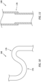
- the fluid conduit 168 may be configured with one or more bends 176. These bends 176 may be provided to facilitate the radial and/or axial compliance / movement between the fluid damper 146 and the stationary structure 172 of FIG. 9 .
- the fluid conduit 168 may also or alternatively be provided with a slip joint 178 to facilitate the radial compliance / movement between the fluid damper 146 and the stationary structure 172 of FIG. 9 .
- the first sun gear 98 and the second sun gear 108 may each be independently connected (e.g., connected in parallel) to the low speed rotating assembly 68 and its low speed shaft 66. In other embodiments, however, the second sun gear 108 may be connected to the low speed rotating assembly 68 and its low speed shaft 66 through the first sun gear 98.
- the second sun gear 108 may be rotationally fixed to the first sun gear 98.
- the first sun gear 98 may be connected to the low speed rotating assembly 68 and its low speed shaft 66 through the second sun gear 108.
- the first sun gear 98 for example, may be rotationally fixed to the second sun gear 108.
- the low speed rotating assembly 68 and its low speed shaft 66 may be connected to the transmission 76 (see FIG. 1 ) and, thus, the second propulsor rotor 24 independent of (e.g., in parallel with) geartrain 72.
- the transmission 76 and, thus, the second propulsor rotor 24 may be coupled to the low speed rotating assembly 68 and its low speed shaft 66 through the first sun gear 98 or the second sun gear 108, but not though the rest of the first gear system 94 and the second gear system 96.
- the low speed rotating assembly 68 may be configured without a compressor rotor.
- the low speed rotating assembly 68 may include a low pressure compressor (LPC) rotor 58' arranged within a low pressure compressor (LPC) section 46A of the compressor section 46.
- the compressor rotor 58 may be a high pressure compressor (HPC) rotor 58 within a high pressure compressor (HPC) section 46B of the compressor section 46.
- the engine core 26 may have various configurations other than those described above.
- the engine core 26, for example, may be configured with a single spool, with two spools (e.g., see FIGS. 1 and 12 ), or with more than two spools.
- the engine core 26 may be configured with one or more axial flow compressor sections, one or more radial flow compressor sections, one or more axial flow turbine sections and/or one or more radial flow turbine sections.
- the engine core 26 may be configured with any type or configuration of annular, tubular (e.g., CAN), axial flow and/or reverser flow combustor. The present disclosure therefore is not limited to any particular types or configurations of gas turbine engine cores.
- the engine core 26 of the present disclosure may drive more than the two propulsor rotors 22 and 24, or a single one of the propulsor rotors 22, 24 and/or one or more other mechanical loads; e.g., electric machines, electric generators, electric motors, etc.
- the aircraft propulsion system 20, for example, may include two or more of the first propulsor rotors 22 and/or two or more of the second propulsor rotors 24.
- the aircraft propulsion system 20 of FIG. 13 includes multiple second propulsor rotors 24 rotatably driven by the low speed rotating assembly 68. These second propulsor rotors 24 may rotate about a common axis.
- each second propulsor rotor 24 may rotate about a discrete axis where, for example, the second propulsor rotors 24 are laterally spaced from one another and coupled to the low speed rotating assembly 68 through a power splitting geartrain 180.
Landscapes
- Engineering & Computer Science (AREA)
- General Engineering & Computer Science (AREA)
- Mechanical Engineering (AREA)
- Chemical & Material Sciences (AREA)
- Combustion & Propulsion (AREA)
- Retarders (AREA)
Abstract
Description
- This invention relates generally to a turbine engine and, more particularly, to a geartrain for the turbine engine.
- Various types and configurations of geartrains and support systems for geartrains for an aircraft propulsion system are known in the art. While these known aircraft propulsion system geartrains and support systems have various benefits, there is still room in the art for improvement.
- According to a first aspect of the invention, an engine assembly is provided that includes a geartrain, a device and a fluid damper. The geartrain is configured as or otherwise includes an epicyclic gear system. A first component of the geartrain is rotatable about an axis. The device is configured to brake and/or lock rotation of the first component of the geartrain about the axis. The device is configured as or otherwise includes a device structure. The fluid damper engages the device structure. The fluid damper is configured to damp vibrations in the device.
- According to another aspect of the invention, another engine assembly is provided that includes a geartrain, a brake, a fluid damper and a lubricant circuit. The geartrain includes a sun gear, a ring gear, a plurality of intermediate gears and a carrier. The sun gear is rotatable about an axis. The ring gear circumscribes the sun gear. The intermediate gears are arranged circumferentially about the axis in an array. Each of the intermediate gears are radially between and meshed with the sun gear and the ring gear. Each of the intermediate gears is rotatably mounted to the carrier. The brake is configured to brake rotation of the ring gear or the carrier about the axis. The brake includes a brake housing. The fluid damper is configured to damp vibrations in the brake. The fluid damper circumscribes the brake housing with a lubricant plenum formed by and radially between the fluid damper and the brake housing. The lubricant circuit is configured to deliver lubricant to the lubricant plenum.
- According to still another aspect of the invention, another engine assembly is provided that includes a geartrain, a lock device, a fluid damper and a lubricant circuit. The geartrain includes a sun gear, a ring gear, a plurality of intermediate gears and a carrier. The sun gear is rotatable about an axis. The ring gear circumscribes the sun gear. The intermediate gears are arranged circumferentially about the axis in an array. Each of the intermediate gears is radially between and meshed with the sun gear and the ring gear. Each of the intermediate gears is rotatably mounted to the carrier. The lock device is configured to lock rotation of the ring gear or the carrier about the axis. The lock device includes a device housing. The fluid damper is configured to damp vibrations in the lock device. The fluid damper circumscribes the device housing with a lubricant plenum formed by and radially between the fluid damper and the device housing. The lubricant circuit is configured to deliver lubricant to the lubricant plenum.
- The following optional features may be applied individually, or in any combination, to any of the above aspects of the invention.
- The device structure may be configured as or otherwise include a device housing.
- The fluid damper may circumscribe the device structure. A lubricant plenum may be formed by and radially between the fluid damper and the device structure.
- The engine assembly may include a lubricant circuit configured to deliver lubricant to the lubricant plenum.
- The engine assembly may include a first seal element and a second seal element. The first seal element may be radially between and engage the device structure and the fluid damper. The second seal element may be radially between and engage the device structure and the fluid damper. The lubricant plenum may extend axially between the first seal element and the second seal element.
- The lubricant plenum may be configured as or otherwise include an annular channel radially outboard and adjacent the device structure. The annular channel may extend radially into and axially within the fluid damper.
- The engine assembly may include a stationary structure. The fluid damper may be connected to the stationary structure through a compliant coupling.
- The compliant coupling may be configured to facilitate shifting between the fluid damper and the stationary structure.
- The device may be configured as or otherwise include a lock device configured to: lock the rotation of the first component of the geartrain about the axis when the lock device is engaged; and unlock the rotation of the first component of the geartrain about the axis when the lock device is disengaged.
- The lock device may be configured as or otherwise include a splined coupling.
- The device may be configured as or otherwise include a brake configured to brake the rotation of the first component of the geartrain about the axis when the brake is engaged.
- The brake may include a rotating component and a rotationally fixed component. The brake may be configured to axially engage the rotationally fixed component with the rotating component to brake the rotation of the first component of the geartrain about the axis.
- The brake may be configured as or otherwise include a disk brake.
- The first component of the geartrain may be configured as or otherwise include a carrier.
- The first component of the geartrain may be configured as or otherwise include a ring gear.
- The epicyclic gear system may be a first epicyclic gear system of the geartrain, and the geartrain may also include a second epicyclic gear system interconnected with the first epicyclic gear system.
- The engine assembly may also include a propulsor rotor and a rotating assembly. The rotating assembly may include a turbine rotor. The rotating assembly may be configured to drive rotation of the propulsor rotor through the geartrain.
- A speed ratio between the rotating assembly and the propulsor rotor may be configured to change from a first ratio to a second ratio by actuating the device.
- The engine assembly may also include a second propulsor rotor rotatable with the rotating assembly. The rotating assembly may be configured to drive rotation of the second propulsor rotor.
- The rotating assembly may be coupled to the second propulsor rotor independent of the geartrain.
- The axis may be a first axis, and the first propulsor rotor may be rotatable about the first axis. The second propulsor rotor may be rotatable about a second axis that is angularly offset from the first axis.
- The engine assembly may include an engine core. The engine core may include a compressor section, a combustor section, a turbine section and the rotating assembly. The turbine section may include the turbine rotor.
- The invention may include any one or more of the individual features disclosed above and/or below alone or in any combination thereof.
- The foregoing features and the operation of the invention will become more apparent in light of the following description and the accompanying drawings.
-
-
FIG. 1 is a partial, schematic illustration of an aircraft propulsion system. -
FIG. 2 is a schematic illustration of a portion of a drivetrain with a geartrain. -
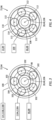
FIG. 3 is a schematic illustration of a first gear system of the geartrain coupled with various components of the aircraft propulsion system. -
FIG. 4 is a schematic illustration of a second gear system of the geartrain coupled with various components of the aircraft propulsion system. -
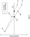
FIG. 5 is a graph depicting changes to rotational speeds during various modes of propulsion system operation. -
FIG. 6 is a partial, side sectional illustration of a rotating assembly configured with a brake. -
FIG. 7 is a partial, side sectional schematic illustration of a lock device. -
FIG. 8 is a cross-sectional illustration of the lock device ofFIG. 7 . -
FIG. 9 is a side sectional schematic illustration of a portion of an assembly for the aircraft propulsion system with a fluid damper. -
FIGS. 10 and 11 are illustrations of portions of a fluid conduit with various compliant sections. -
FIG. 12 is a partial, schematic illustration of a gas turbine engine core. -
FIG. 13 is a partial, schematic illustration of a rotating structure coupled to and driving multiple propulsor rotors for generating propulsive lift. -
FIG. 1 schematically illustrates apropulsion system 20 for an aircraft. The aircraft may be an airplane, a helicopter, a drone (e.g., an unmanned aerial vehicle (UAV)), a spacecraft or any other manned or unmanned aerial vehicle or system. This aircraft may be configured as a vertical take-off and landing (VTOL) aircraft or a short take-off and vertical landing (STOVL) aircraft. Theaircraft propulsion system 20 ofFIG. 1 , for example, is configured to generate power for first direction propulsion (e.g., propulsive thrust) during a first mode of operation and to generate power for second direction propulsion (e.g., propulsive lift) during a second mode of operation, where the first direction is different than (e.g., angularly offset from) the second direction. The first mode may be a horizontal flight mode (e.g., a forward flight mode) where the first direction propulsion is substantially horizontal propulsive thrust; e.g., within five degrees (5°), ten degrees (10°), etc. of a horizontal axis. The second mode may be a vertical flight and/or hover mode where the second direction propulsion is substantially vertical propulsive lift; e.g., within five degrees (5°), ten degrees (10°), etc. of a vertical axis. Theaircraft propulsion system 20, of course, may also be configured to generate both the first direction propulsion (e.g., horizontal propulsion) and the second direction propulsion (e.g., vertical propulsion) during a third mode (e.g., a transition mode) of operation. - The
aircraft propulsion system 20 ofFIG. 1 includes one or more bladed propulsor rotors such as, for example, at least one bladedfirst propulsor rotor 22 and at least one bladedsecond propulsor rotor 24. Theaircraft propulsion system 20 ofFIG. 1 also includes a gas turbine engine with a core 26 configured to rotatably drive the one or more propulsor rotors - thefirst propulsor rotor 22 and/or thesecond propulsor rotor 24. - The
first propulsor rotor 22 may be configured as a ducted rotor such as a fan rotor. Of course, in other embodiments, thefirst propulsor rotor 22 may alternatively be configured as an open rotor (e.g., an un-ducted rotor) such as a propeller rotor, a pusher fan rotor or the like. Thefirst propulsor rotor 22 ofFIG. 1 is rotatable about a first rotor axis 28. This first rotor axis 28 is an axial centerline of thefirst propulsor rotor 22 and may be horizontal when the aircraft is on ground and/or during level aircraft flight. Thefirst propulsor rotor 22 includes at least a first rotor disk 29 (or a hub) and a plurality of first rotor blades 30 (one visible inFIG. 1 ); e.g., fan blades. Thefirst rotor blades 30 are distributed circumferentially around thefirst rotor disk 29 in an annular array. Each of thefirst rotor blades 30 is connected to and projects radially (relative to the first rotor axis 28) out from thefirst rotor disk 29. - The
second propulsor rotor 24 may be configured as an open rotor such as a propeller rotor or a helicopter (e.g., main) rotor. Of course, in other embodiments, thesecond propulsor rotor 24 may alternatively be configured as a ducted rotor such as a fan rotor; e.g., see dashed line duct. Thesecond propulsor rotor 24 ofFIG. 1 is rotatable about asecond rotor axis 32. Thissecond rotor axis 32 is an axial centerline of thesecond propulsor rotor 24 and may be vertical when the aircraft is on the ground and/or during level aircraft flight. Thesecond rotor axis 32 is angularly offset from the first rotor axis 28 by an includedangle 34; e.g., an acute angle or a right angle. This includedangle 34 may be between sixty degrees (60°) and ninety degrees (90°); however, the present disclosure is not limited to such an exemplary relationship. Thesecond propulsor rotor 24 includes at least a second rotor disk 36 (or a hub) and a plurality ofsecond rotor blades 38; e.g., open rotor blades. Thesecond rotor blades 38 are distributed circumferentially around thesecond rotor disk 36 in an annular array. Each of thesecond rotor blades 38 is connected to and projects radially (relative to the second rotor axis 32) out from thesecond rotor disk 36. - The
engine core 26 extends axially along a core axis 40 from a forward,upstream airflow inlet 42 into theengine core 26 to an aft, downstream combustion products exhaust 44 from theengine core 26. The core axis 40 may be an axial centerline of theengine core 26 and may be horizontal when the aircraft is on the ground and/or during level aircraft flight. This core axis 40 may be parallel (e.g., coaxial) with the first rotor axis 28 and, thus, angularly offset from thesecond rotor axis 32. Theengine core 26 ofFIG. 1 includes acompressor section 46, acombustor section 47 and aturbine section 48. Theturbine section 48 ofFIG. 1 includes a high pressure turbine (HPT)section 48A and a low pressure turbine (LPT)section 48B (also sometimes referred to as a power turbine section). - The engine sections 46-48B may be arranged sequentially along the core axis 40 within an
engine housing 50. Thisengine housing 50 includes an inner case 52 (e.g., a core case) and an outer case 54 (e.g., a fan case). Theinner case 52 may house one or more of the engine sections 46-48B; e.g., theengine core 26. Theouter case 54 may house thefirst propulsor rotor 22. Theouter case 54 ofFIG. 1 also axially overlaps and extends circumferentially about (e.g., completely around) theinner case 52 thereby at least partially forming a (e.g., annular)bypass flowpath 56 radially between theinner case 52 and theouter case 54. - Each of the
engine sections respective engine section - The
compressor rotor 58 is connected to theHPT rotor 59 through ahigh speed shaft 62. At least (or only) theseengine components speed rotating assembly 64; e.g., a high speed spool. This highspeed rotating assembly 64 is rotatable about the core axis 40. TheLPT rotor 60 is connected to alow speed shaft 66. At least (or only) theseengine components speed rotating assembly 68; e.g., a low speed spool. This lowspeed rotating assembly 68 is rotatable about the core axis 40. The lowspeed rotating assembly 68 and, more particularly, itslow speed shaft 66 may project axially through a bore of the highspeed rotating assembly 64 and itshigh speed shaft 62. - The
aircraft propulsion system 20 ofFIG. 1 and its turbine engine include adrivetrain 70 that couples the lowspeed rotating assembly 68 to thefirst propulsor rotor 22 and that couples the lowspeed rotating assembly 68 to thesecond propulsor rotor 24. Thedrivetrain 70 ofFIG. 1 includes ageartrain 72, atransmission 76 and agearing 78; e.g., bevel gearing. Thedrivetrain 70 ofFIG. 1 also includes one ormore shafts speed rotating assembly 68 and itslow speed shaft 66 to thesecond propulsor rotor 24. Thedrivetrain 70 may also include one or more intermediate torque transmission devices for coupling thegeartrain 72 to thefirst propulsor rotor 22; e.g., afirst propulsor shaft 84. - An input into the
geartrain 72 is coupled to the lowspeed rotating assembly 68 and itslow speed shaft 66, where the lowspeed rotating assembly 68 forms a power input for thegeartrain 72. An output from thegeartrain 72 is coupled to thefirst propulsor rotor 22 through thefirst propulsor shaft 84, where thefirst propulsor rotor 22 forms a power output (e.g., load) for thegeartrain 72. - An input into the
transmission 76 may be coupled to the lowspeed rotating assembly 68 independent of thegeartrain 72. The lowspeed rotating assembly 68, for example, may be coupled to the input of thegeartrain 72 and the input of thetransmission 76 in parallel. The input of thetransmission 76 ofFIG. 1 , in particular, is (e.g., directly or indirectly) connected to theLPT rotor 60 through thelow speed shaft 66; e.g., without passing through thegeartrain 72. An output from thetransmission 76 is connected to an input into thegearing 78 through thetransmission output shaft 80. - The
transmission 76 may be configured to selectively couple (e.g., transfer mechanical power between) the lowspeed rotating assembly 68 and thetransmission output shaft 80. During the first mode of operation, for example, thetransmission 76 may be configured to decouple the lowspeed rotating assembly 68 from thetransmission output shaft 80, thereby decoupling the lowspeed rotating assembly 68 from thesecond propulsor rotor 24. During the second mode of operation (and the third mode of operation), thetransmission 76 may be configured to couple the lowspeed rotating assembly 68 with thetransmission output shaft 80, thereby coupling the lowspeed rotating assembly 68 with thesecond propulsor rotor 24. Thetransmission 76 may be configured as a clutched transmission or a clutchless transmission. - An output from the
gearing 78 is connected to thesecond propulsor rotor 24 through thesecond propulsor shaft 82. Thisgearing 78 provides a coupling between thetransmission output shaft 80 rotating about the axis 28, 40 and thesecond propulsor shaft 82 rotating about thesecond rotor axis 32. Thegearing 78 may also provide a speed change mechanism between thetransmission output shaft 80 and thesecond propulsor shaft 82. Thegearing 78, however, may alternatively provide a 1:1 rotational coupling between thetransmission output shaft 80 and thesecond propulsor shaft 82 such that theseshafts gearing 78 and thetransmission output shaft 80 may be omitted where the functionality of thegearing 78 is integrated into thetransmission 76. In still other embodiments, thetransmission 76 may be omitted where decoupling of thesecond propulsor rotor 24 is not required and/or where an optional additional speed change between the lowspeed rotating assembly 68 and thesecond propulsor rotor 24 is not required. - During operation of the
aircraft propulsion system 20, air enters theengine core 26 through thecore inlet 42. This air is directed into a (e.g., annular)core flowpath 86, which core flowpath 86 extends sequentially through thecompressor section 46, thecombustor section 47, theHPT section 48A and theLPT section 48B from thecore inlet 42 to thecore exhaust 44. The air within thiscore flowpath 86 may be referred to as core air. - The core air is compressed by the
compressor rotor 58 and directed into a (e.g., annular)combustion chamber 88 of a (e.g., annular)combustor 90 in thecombustor section 47. Fuel is injected into thecombustion chamber 88 through one or more fuel injectors 92 (one visible inFIG. 1 ) and mixed with the compressed core air to provide a fuel-air mixture. This fuel-air mixture is ignited and combustion products thereof flow through and sequentially cause theHPT rotor 59 and theLPT rotor 60 to rotate. The rotation of theHPT rotor 59 drives rotation of the highspeed rotating assembly 64 and itscompressor rotor 58. The rotation of theLPT rotor 60 drives rotation of the lowspeed rotating assembly 68. The rotation of the lowspeed rotating assembly 68 drives rotation of thefirst propulsor rotor 22 through thegeartrain 72 during one or more modes of operation; e.g., the first, the second and the third modes of operation. The rotation of the lowspeed rotating assembly 68 drives rotation of the second propulsor rotor 24 (e.g., independent of the geartrain 72) during one or more modes of operation; e.g., the second and the third modes of operation. During the first mode of operation, thetransmission 76 may decouple the lowspeed rotating assembly 68 from thesecond propulsor rotor 24 such that the lowspeed rotating assembly 68 does not drive rotation of thesecond propulsor rotor 24. Thesecond propulsor rotor 24 may thereby be stationary (or windmill) during the first mode of operation. - During the first and the third modes of operation, the rotation of the
first propulsor rotor 22 propels bypass air (separate from the core air) through theaircraft propulsion system 20 and itsbypass flowpath 56 to provide the first direction propulsion; e.g., the forward, horizontal thrust. During the second and the third modes of operation, the rotation of thesecond propulsor rotor 24 propels additional air (separate from the core air and the bypass air) to provide the second direction propulsion; e.g., vertical lift. The aircraft may thereby takeoff, land and/or otherwise hover during the second and the third modes of operation, and the aircraft may fly forward or otherwise move during the first and the third modes of operation. The bypass air may also flow through thebypass flowpath 56 during the second and the third modes of operation; however, a quantity of the bypass air flowing through thebypass flowpath 56 during the second mode of operation may be de minimis as described below in further detail. - Referring to
FIG. 2 , thegeartrain 72 may include multiple (e.g., epicyclic)interconnected gear systems FIGS. 2 and3 , thefirst gear system 94 has a plurality of first gear system components including afirst sun gear 98, afirst ring gear 100, a plurality of firstintermediate gears 102 and afirst carrier 104. Thefirst sun gear 98 is rotatable about a rotational axis 106 of thegeartrain 72, which rotational axis 106 may be parallel (e.g., coaxial) with the axis 28, 40. Thefirst ring gear 100 circumscribes thefirst sun gear 98 and the first intermediate gears 102. Thefirst ring gear 100 is rotatable about the axis 28, 40, 106. The firstintermediate gears 102 are arranged circumferentially about the axis 28, 40, 106 and thefirst sun gear 98 in an array. Each of the firstintermediate gears 102 is disposed radially between and meshed with thefirst sun gear 98 and thefirst ring gear 100. Each of the firstintermediate gears 102 is rotatably mounted to thefirst carrier 104. Thefirst carrier 104 is rotatable about the axis 28, 40, 106. - Referring to
FIGS. 2 and4 , thesecond gear system 96 has a plurality of second gear system components including asecond sun gear 108, asecond ring gear 110, a plurality of secondintermediate gears 112 and asecond carrier 114. Thesecond sun gear 108 is rotatable about the axis 28, 40, 106. Thesecond ring gear 110 circumscribes thesecond sun gear 108 and the second intermediate gears 112. Thesecond ring gear 110 is rotatable about the axis 28, 40, 106. The secondintermediate gears 112 are arranged circumferentially about the axis 28, 40, 106 and thesecond sun gear 108 in an array. Each of the secondintermediate gears 112 is disposed radially between and meshed with thesecond sun gear 108 and thesecond ring gear 110. Each of the secondintermediate gears 112 is rotatably mounted to thesecond carrier 114. Thesecond carrier 114 is rotatable about the axis 28, 40, 106. Thissecond carrier 114 ofFIG. 2 is coupled to (e.g., via aninter-gear system shaft 115 and/or another drive element) and rotatable with thefirst ring gear 100, where thesecond carrier 114 and thefirst ring gear 100 are configured to rotate at a common rotational velocity. - The
first propulsor rotor 22 is coupled to thegeartrain 72 and itssecond gear system 96 through thesecond ring gear 110. The first propulsor shaft 84 (and/or another drive element), for example, may couple thefirst propulsor rotor 22 to thesecond ring gear 110. Thefirst propulsor shaft 84 ofFIG. 2 extends between and is connected to thefirst propulsor rotor 22 and thesecond ring gear 110. The lowspeed rotating assembly 68 and itslow speed shaft 66 are coupled to thegeartrain 72 and itsfirst gear system 94 through thefirst sun gear 98. The lowspeed rotating assembly 68 and itslow speed shaft 66 are also coupled to thegeartrain 72 and itssecond gear system 96 through thesecond sun gear 108. Thefirst sun gear 98 and thesecond sun gear 108 ofFIG. 2 , for example, are each (e.g., independently) connected to the lowspeed rotating assembly 68 and itslow speed shaft 66. With such an arrangement, the lowspeed rotating assembly 68 and itsLPT rotor 60 are configured to (e.g., independently) drive rotation of thefirst sun gear 98 and thesecond sun gear 108, where thefirst sun gear 98, thesecond sun gear 108 and theLPT rotor 60 are rotate at a common rotational velocity. - The
aircraft propulsion system 20 and itsdrivetrain 70 ofFIG. 2 includes one or more rotation control devices configured to brake and/or lock rotation of one or more components of thegeartrain 72 / its gear systems(s) 94 and/or 96 about the axis 28, 40, 106. These rotation control devices may include one ormore brakes more lock devices first brake 116A and/or thefirst lock device 118A may be located at afirst location 120A, or another suitable location. Thesecond brake 116B and/or thesecond lock device 118B may be located at asecond location 120B, or another suitable location. - The
first brake 116A ofFIG. 2 is configured to brake (e.g., slow and/or stop) rotation of thefirst carrier 104 about the axis 28, 40, 106. Thesecond lock device 118B is configured to lock (e.g., fix, prevent) rotation of thefirst ring gear 100 and thesecond carrier 114 about the axis 28, 40, 106, for example, following the braking of thesecond carrier 114 to a zero rotational speed about the axis 28, 40, 106 using thesecond brake 116B. When thesecond carrier 114 is rotationally fixed (e.g., during the second mode of operation ofFIG. 5 ), a rotational speed of thefirst propulsor rotor 22 may decrease (compared to when thesecond carrier 114 is free to rotate). - Reducing the rotational speed of the
first propulsor rotor 22 during, for example, the second mode of operation reduces or substantially eliminates (e.g., de minimis) the first direction propulsive thrust generated by thefirst propulsor rotor 22. Reducing first propulsor rotor thrust may, in turn, increase power available for driving rotation of thesecond propulsor rotor 24 and/or facilitate substantial second direction aircraft movement; e.g., without first direction aircraft movement. However, maintaining some rotation of thefirst propulsor rotor 22 may maintain lubrication of one or more bearings (e.g.,bearings 122 inFIG. 2 ) supporting thefirst propulsor rotor 22 and/or prevent bearing related damage. For example, when a component supported by a bearing is not rotating, shock loads may damage one of more internal components of the bearing. Examples of such bearing damage may include, but are not limited to, brinelling and false brinelling. Maintaining some rotation of thefirst propulsor rotor 22 ofFIG. 1 may also or alternatively prevent an exhaust backflow through thebypass flowpath 56 into thecore inlet 42. Maintaining some rotation of thefirst propulsor rotor 22 may still also or alternatively prevent debris (e.g., sand, dirt, dust, etc.) from entering thecore inlet 42 during the second mode of operation where the aircraft is more likely to be near the ground; e.g., for landing or takeoff. - The
second brake 116B ofFIG. 2 is configured to brake (e.g., slow and/or stop) rotation of thefirst ring gear 100 about the axis 28, 40, 106 and, thus, rotation of thesecond carrier 114 about the axis 28, 40, 106. Thefirst lock device 118A is configured to lock (e.g., fix, prevent) rotation of thefirst carrier 104 about the axis 28, 40, 106. With this arrangement, thegeartrain 72 and itsfirst gear system 94 and itssecond gear system 96 are configured to transfer additional power from the lowspeed rotating assembly 68 and itsLPT rotor 60 to thefirst propulsor rotor 22 and any drivetrain element(s) therebetween (when included). This power transfer may be substantially all (e.g., minus losses in the drivetrain 70) of the power output from the lowspeed rotating assembly 68 and itsLPT rotor 60 when thesecond propulsor rotor 24 is rotationally decoupled from the lowspeed rotating assembly 68; e.g., using thetransmission 76 ofFIG. 1 . Thegeartrain 72 may thereby provide a multi-speed transmission between the lowspeed rotating assembly 68 and thefirst propulsor rotor 22, where a speed ratio between the lowspeed rotating assembly 68 and thefirst propulsor rotor 22 during the second mode is less than a speed ratio between the lowspeed rotating assembly 68 and thefirst propulsor rotor 22 during the first mode. - To enter the third mode of operation from the first mode of operation, the
first lock device 118A may be disengaged and/or thefirst brake 116A may be released (if currently applied). Thesecond propulsor rotor 24 may thereby begin to rotate along with the already rotatingfirst propulsor rotor 22. Similarly, to enter the third mode of operation from the second mode of operation, thesecond lock device 118B may be disengaged and/or thesecond brake 116B may be released (if currently applied). Thefirst propulsor rotor 22 may thereby begin to rotate faster along with the already rotatingsecond propulsor rotor 24. When both of thefirst propulsor rotor 22 and thesecond propulsor rotor 24 are rotating / free to rotate, thedrivetrain 70 may transfer (e.g., all, minus losses in the drivetrain 70) the power output from the lowspeed rotating assembly 68 and itsLPT rotor 60 to (a) thefirst propulsor rotor 22 and the drivetrain element(s) therebetween and (b) thesecond propulsor rotor 24 and the drivetrain element(s) therebetween (e.g., independent of thegeartrain 72 and itsfirst gear system 94 and its second gear system 96). - Referring to
FIG. 6 , thefirst brake 116A and/or thesecond brake 116B may each be configured as or otherwise include adisk brake 124. Thedisk brake 124 ofFIG. 6 includes at least onebrake rotor 126 and one ormore brake pads 128. Thebrake rotor 126 is a rotating component of thedisk brake 124, and is rotatable with therespective geartrain member brake rotor 126, for example, may be connected to and rotatable with therespective geartrain member respective geartrain member brake pads 128 are rotationally fixed components of thedisk brake 124; e.g., rotationally fixed about the axis 28, 40, 106. Thebrake pads 128 ofFIG. 6 , for example, are anchored to abrake housing 130, whichbrake housing 130 is connected to / anchored to the engine housing 50 (seeFIG. 1 ) and/or an airframe of the aircraft. Thebrake pads 128 may be actuated by one or more brake actuators 132 (e.g., hydraulic brake actuators) to move thebrake pads 128 from an open position to a closed position. In the open position, thebrake pads 128 are spaced from and do not engage (e.g., contact) the brake rotor 126 (see position ofFIG. 6 ). In the closed position, thebrake pads 128 engage (e.g., contact) and clamp onto (e.g., squeeze) thebrake rotor 126. Frictional rubbing between thebrake pads 128 and thebrake rotor 126 is operable to brake rotation of thebrake rotor 126 and, thus, therespective geartrain member 104, 100 (or another rotating element) connected thereto. The first and the second brakes 116 of the present disclosure, however, are not limited to such an exemplary disk brake configuration. For example, it is contemplated the first and/or thesecond brake 116B may alternatively be configured as another type of brake with (e.g., axially and/or radially) engageable rotating brake component(s) and rotationally fixed brake component(s), such as a drum brake or a set of clutch plates. - Referring to
FIG. 7 , thefirst lock device 118A and/or thesecond lock device 118B may each be configured as a splined lock device; e.g., a splined coupling. The lock device 118 ofFIG. 7 , for example, includes an inner lock element 134 (e.g., a splined shaft), an outer lock element 136 (e.g., a splined sleeve) and anactuator 138. Theinner lock element 134 is a rotating component of the lock device 118, and is rotatable about the axis 28, 40, 106. Theouter lock element 136 is a rotationally fixed component of the lock device 118; e.g., rotationally fixed about the axis 28, 40, 106. However, theouter lock element 136 ofFIG. 7 is configured to translate axially along a guide (e.g., a rail, a track, etc.) fixed to or part of alock device housing 139, which lockdevice housing 139 may be connected to / anchored to the engine housing 50 (seeFIG. 1 ) and/or an airframe of the aircraft. Theactuator 138 is configured to move (e.g., axially translate) theouter lock element 136 along the axis 28, 40, 106 and theinner lock element 134 between an unlocked position (see dashed line inFIG. 7 ) and a locked position (see solid line inFIG. 7 ; see alsoFIG. 8 ). At the unlocked position,inner splines 140 of theouter lock element 136 are disengaged (e.g., spaced) fromouter splines 142 of theinner lock element 134. At the locked position, theinner splines 140 of theouter lock element 136 are engaged (e.g., meshed) with theouter splines 142 of the inner lock element 134 (see alsoFIG. 8 ). With this arrangement, when the lock device 118 is unlocked and itsouter lock element 136 is in the unlocked position, theinner lock element 134 may rotate (e.g., freely, unencumbered by the outer lock element 136) about the axis 28, 40, 106. However, when the lock device 118 is locked and itsouter lock element 136 is in the locked position ofFIG. 8 , theouter lock element 136 is meshed with theinner lock element 134 and prevents rotation of theinner lock element 134 about the axis 28, 40, 106. - Referring to
FIGS. 2 and7 , theinner lock element 134 of thefirst lock device 118A may be configured as part of or may be attached (directly or indirectly) to thefirst carrier 104, or any other element rotatable therewith. Theinner lock element 134 of thesecond lock device 118B may be configured as part of or may be attached (directly or indirectly) to thefirst ring gear 100, or any other element rotatable therewith. While theinner lock element 134 ofFIGS. 7 and 8 is described as the rotating element and theouter lock element 136 is described as the rotationally fixed element, the operation of these elements may be switched in other embodiments. In particular, theinner lock element 134 may alternatively be configured as the rotationally fixed element and axially translatable by theactuator 138, and theouter lock element 136 may be configured as the rotating element. Furthermore, various other types of rotational lock devices are known in the art, and the present disclosure is not limited to any particular ones thereof. - Referring to
FIGS. 2 and9 , theaircraft propulsion system 20 and its turbine engine may include adamper assembly 144 for supporting operation of one or more of the rotation control devices; e.g., the brake 116 and/or the lock device 118. Thisdamper assembly 144 includes afluid damper 146 and a fluid circuit 148 (e.g., a lubricant circuit) configured to deliver fluid (e.g., lubricant) to thefluid damper 146. - The
fluid damper 146 is located with a structure 150 of the rotation control device(s); e.g., the brake 116 and/or the lock device 118. This control device structure 150 may be a housing for the rotation control device(s); e.g., thebrake housing 130 and/or thelock device housing 139. Alternatively, the control device structure 150 may be another element supporting and/or coupled to the rotationally fixed component(s) of the rotation control device(s); e.g., thebrake pads 128 ofFIG. 6 or theouter lock element 136 ofFIG. 7 . Thefluid damper 146 ofFIG. 9 is disposed radially outboard of the control device structure 150. Here, a radialinner side 152 of thefluid damper 146 faces a (e.g., cylindrical) damper land surface 154 of the control device structure 150 at a radial outer side 156 of the control device structure 150. Thefluid damper 146 extends axially along and circumferentially about the axis 28, 40, 106 and the control device structure 150 and its damper land surface 154. Thefluid damper 146 thereby axially overlaps and circumscribes at least a portion of the control device structure 150 and its damper land surface 154. - The
fluid damper 146 ofFIG. 9 includes acoupling passage 158 and anannular channel 160. Thecoupling passage 158 extends radially (in a radial inward direction towards the axis 28, 40, 106) into thefluid damper 146 to thechannel 160. Thechannel 160 extends radially (in a radial outward direction away from the axis 28, 40, 106) into thefluid damper 146 to thecoupling passage 158. Thischannel 160 extends axially within thefluid damper 146 between opposing axial sidewalls, and may have a larger axial width than thecoupling passage 158. Thechannel 160 extends within the fluid coupling circumferentially about (e.g., completely around) the axis 28, 40, 106. - The
fluid damper 146 is disposed radially adjacent (but, slightly radially spaced from) the control device structure 150 and its damper land surface 154. With this arrangement, a fluid plenum 162 (e.g., an annular lubricant plenum) is formed by and radially between the control device structure 150 and thefluid damper 146. Thisfluid plenum 162 includes thechannel 160 as well as aradial clearance gap 164 between an inner surface of thefluid damper 146 at itsinner side 152 and the damper land surface 154. Thefluid plenum 162 and itsclearance gap 164 are axially bounded by (e.g., extend axially between) a plurality of seal elements 166 (e.g., annular seal elements, seal rings, etc.), where eachseal element 166 is radially between and engaged with (e.g., contacts) thefluid damper 146 and the control device structure 150. - The
fluid circuit 148 ofFIG. 9 includes a fluid conduit 168 (e.g., a lubricant conduit), thecoupling passage 158 and thefluid plenum 162. Thefluid conduit 168 is fluidly coupled to thefluid plenum 162 through thecoupling passage 158. Thefluid conduit 168 is configured to receive a flow of fluid such as lubricant from a fluid source 170 (e.g., a lubricant reservoir and/or a lubricant pump), and direct that fluid flow through thecoupling passage 158 and into thefluid plenum 162. The fluid within thefluid plenum 162 provides a viscous medium between thefluid damper 146 and the control device structure 150, which viscous medium facilitates fluidic damping of vibrations in the control device structure 150. With such an arrangement, referring toFIG. 2 , whirl of a component of the geartrain 72 (e.g., the first carrier 104) operationally coupled to the respective rotation control device(s) (e.g., the brake 116 and/or the lock device 118) may be reduced or eliminated. That component of thegeartrain 72 may thereby be configured without a bearing (e.g., a centering bearing) supporting rotation thereof about the axis 28, 40, 106, which may also reduce or eliminate bending moments on the component of thegeartrain 72. The present disclosure, however, is not limited to such an exemplary arrangement. - The
fluid damper 146 ofFIG. 9 may be connected to astationary structure 172 of theaircraft propulsion system 20 through acompliant coupling 174; e.g., a squirrel cage coupling, a spring coupling, etc. Thiscompliant coupling 174 is configured to facilitate (e.g., slight) radial and/or axial movement between thefluid damper 146 and thestationary structure 172, which may reduce bending moment loads, vibration loads, etc. on thefluid damper 146 and/or enable thefluid damper 146 to follow (e.g., slight) shifting of the control device structure 150. - In some embodiments, referring to
FIGS. 2 and9 , twofluid dampers 146 may be included and configured to act separately atlocations - In some embodiments, referring to
FIG. 10 , thefluid conduit 168 may be configured with one or more bends 176. Thesebends 176 may be provided to facilitate the radial and/or axial compliance / movement between thefluid damper 146 and thestationary structure 172 ofFIG. 9 . Referring toFIG. 11 , thefluid conduit 168 may also or alternatively be provided with a slip joint 178 to facilitate the radial compliance / movement between thefluid damper 146 and thestationary structure 172 ofFIG. 9 . - In some embodiments, referring to
FIG. 2 , thefirst sun gear 98 and thesecond sun gear 108 may each be independently connected (e.g., connected in parallel) to the lowspeed rotating assembly 68 and itslow speed shaft 66. In other embodiments, however, thesecond sun gear 108 may be connected to the lowspeed rotating assembly 68 and itslow speed shaft 66 through thefirst sun gear 98. Thesecond sun gear 108, for example, may be rotationally fixed to thefirst sun gear 98. In still other embodiments, thefirst sun gear 98 may be connected to the lowspeed rotating assembly 68 and itslow speed shaft 66 through thesecond sun gear 108. Thefirst sun gear 98, for example, may be rotationally fixed to thesecond sun gear 108. - In some embodiments, referring to
FIG. 2 , the lowspeed rotating assembly 68 and itslow speed shaft 66 may be connected to the transmission 76 (seeFIG. 1 ) and, thus, thesecond propulsor rotor 24 independent of (e.g., in parallel with) geartrain 72. In other embodiments, however, thetransmission 76 and, thus, thesecond propulsor rotor 24 may be coupled to the lowspeed rotating assembly 68 and itslow speed shaft 66 through thefirst sun gear 98 or thesecond sun gear 108, but not though the rest of thefirst gear system 94 and thesecond gear system 96. Thus, while power may be transferred from the lowspeed rotating assembly 68 to thesecond propulsor rotor 24 through the sun gear(s) 98 and/or 108, the output from thegeartrain 72 to thetransmission 76 may still rotate with the lowspeed rotating assembly 68 at a common rotational velocity. - In some embodiments, referring to
FIG. 1 , the lowspeed rotating assembly 68 may be configured without a compressor rotor. In other embodiments, referring toFIG. 12 , the lowspeed rotating assembly 68 may include a low pressure compressor (LPC) rotor 58' arranged within a low pressure compressor (LPC)section 46A of thecompressor section 46. In such embodiments, thecompressor rotor 58 may be a high pressure compressor (HPC)rotor 58 within a high pressure compressor (HPC)section 46B of thecompressor section 46. - The engine core 26 (e.g., see
FIG. 1 ) may have various configurations other than those described above. Theengine core 26, for example, may be configured with a single spool, with two spools (e.g., seeFIGS. 1 and12 ), or with more than two spools. Theengine core 26 may be configured with one or more axial flow compressor sections, one or more radial flow compressor sections, one or more axial flow turbine sections and/or one or more radial flow turbine sections. Theengine core 26 may be configured with any type or configuration of annular, tubular (e.g., CAN), axial flow and/or reverser flow combustor. The present disclosure therefore is not limited to any particular types or configurations of gas turbine engine cores. Furthermore, it is contemplated theengine core 26 of the present disclosure may drive more than the twopropulsor rotors propulsor rotors aircraft propulsion system 20, for example, may include two or more of thefirst propulsor rotors 22 and/or two or more of thesecond propulsor rotors 24. For example, theaircraft propulsion system 20 ofFIG. 13 includes multiplesecond propulsor rotors 24 rotatably driven by the lowspeed rotating assembly 68. Thesesecond propulsor rotors 24 may rotate about a common axis. Alternatively, eachsecond propulsor rotor 24 may rotate about a discrete axis where, for example, thesecond propulsor rotors 24 are laterally spaced from one another and coupled to the lowspeed rotating assembly 68 through apower splitting geartrain 180. - While various embodiments of the present disclosure have been described, it will be apparent to those of ordinary skill in the art that many more embodiments and implementations are possible within the scope of the disclosure. For example, the present disclosure as described herein includes several aspects and embodiments that include particular features. Although these features may be described individually, it is within the scope of the present disclosure that some or all of these features may be combined with any one of the aspects and remain within the scope of the disclosure.
Claims (15)
- An engine assembly comprising:a geartrain (72) comprising an epicyclic gear system (94), a first component (100; 104) of the geartrain rotatable about an axis (28; 40; 106);a device (116, 118) configured to brake and/or lock rotation of the first component of the geartrain (72) about the axis (28; 40; 106), the device comprising a device structure (150); anda fluid damper (146) engaging the device structure (150), the fluid damper (146) configured to damp vibrations in the device.
- The engine assembly of claim 1, wherein the fluid damper (146) circumscribes the device structure (150) and a lubricant plenum (162) is formed by and radially between the fluid damper (146) and the device structure (150).
- The engine assembly of claim 2, further comprising a lubricant circuit (148) configured to deliver lubricant to the lubricant plenum.
- The engine assembly of claim 2 or 3, further comprising:a first seal element (166) radially between and engaging the device structure (150) and the fluid damper (146); anda second seal element (166) radially between and engaging the device structure (150) and the fluid damper (146), the lubricant plenum extending axially between the first seal element (166) and the second seal element (166).
- The engine assembly of any of claims 2 to 4, wherein:the lubricant plenum (162) comprises an annular channel (160) radially outboard and adjacent the device structure (150); andthe annular channel (160) extends radially into and axially within the fluid damper (146).
- The engine assembly of any preceding claim, further comprising a stationary structure (172), the fluid damper (146) connected to the stationary structure (172) through a compliant coupling (174).
- The engine assembly of claim 6, wherein the compliant coupling (174) is configured to facilitate shifting between the fluid damper (146) and the stationary structure (172).
- The engine assembly of any preceding claim, wherein the device comprises a lock device (118) configured to:
lock the rotation of the first component of the geartrain (72) about the axis (28; 40; 106) when the lock device (118) is engaged; and
unlock the rotation of the first component of the geartrain (72) about the axis (28; 40; 106) when the lock device (118) is disengaged, optionally wherein:
the lock device (118) comprises a splined coupling. - The engine assembly of any preceding claim, wherein the device comprises a brake (116) configured to brake the rotation of the first component of the geartrain (72) about the axis (28; 40; 106) when the brake (116) is engaged.
- The engine assembly of claim 9, wherein:
the brake (116) comprises a rotating component (126) and a rotationally fixed component (128); and
the brake (116) is configured to axially engage the rotationally fixed component with the rotating component to brake (116) the rotation of the first component of the geartrain (72) about the axis (28; 40; 106), optionally wherein:
the brake (116) comprises a disk brake (124). - The engine assembly of any preceding claim, wherein the first component of the geartrain (72) comprises a carrier (104).
- The engine assembly of any of claims 1 to 10, wherein the first component of the geartrain (72) comprises a ring gear (100).
- The engine assembly of any preceding claim, wherein the epicyclic gear system is a first epicyclic gear system (94) of the geartrain (72), and the geartrain further comprises a second epicyclic gear system (96) interconnected with the first epicyclic gear system.
- The engine assembly of any preceding claim, further comprising:a propulsor rotor (22); anda rotating assembly (68) comprising a turbine rotor (60), the rotating assembly configured to drive rotation of the propulsor rotor (22) through the geartrain (72),wherein the device is configured such that, when actuated, a speed ratio between the rotating assembly and the propulsor rotor changes from a first ratio to a second ratio.
- The engine assembly of claim 14, further comprising a second propulsor rotor (24) rotatable with the rotating assembly, wherein the rotating assembly is configured to drive rotation of the second propulsor rotor.
Applications Claiming Priority (1)
| Application Number | Priority Date | Filing Date | Title |
|---|---|---|---|
| US18/375,132 US12292107B2 (en) | 2023-09-29 | 2023-09-29 | Fluid damper for turbine engine geartrain assembly |
Publications (1)
| Publication Number | Publication Date |
|---|---|
| EP4530497A1 true EP4530497A1 (en) | 2025-04-02 |
Family
ID=92932695
Family Applications (1)
| Application Number | Title | Priority Date | Filing Date |
|---|---|---|---|
| EP24203743.0A Pending EP4530497A1 (en) | 2023-09-29 | 2024-09-30 | Fluid damper for turbine engine geartrain assembly |
Country Status (2)
| Country | Link |
|---|---|
| US (1) | US12292107B2 (en) |
| EP (1) | EP4530497A1 (en) |
Citations (5)
| Publication number | Priority date | Publication date | Assignee | Title |
|---|---|---|---|---|
| EP3002434A1 (en) * | 2014-10-03 | 2016-04-06 | Rolls-Royce plc | Geared architecture for a gas turbine with squeeze film damper |
| EP3269964A1 (en) * | 2016-07-12 | 2018-01-17 | Rolls-Royce Deutschland Ltd & Co KG | A geared gas turbine engine |
| US20190024582A1 (en) * | 2016-11-15 | 2019-01-24 | Pratt & Whitney Canada Corp. | Gearbox for gas turbine engine |
| CN113915256A (en) * | 2021-10-29 | 2022-01-11 | 北京理工大学 | Elastic damping type gear shifting brake |
| US20220162961A1 (en) * | 2020-11-26 | 2022-05-26 | General Electric Company | System and method for rotor overspeed mitigation |
Family Cites Families (95)
| Publication number | Priority date | Publication date | Assignee | Title |
|---|---|---|---|---|
| US2981063A (en) * | 1957-06-17 | 1961-04-25 | Wickman Axel Charles | Variable speed power transmission mechanisms |
| DE1119675B (en) | 1960-06-14 | 1961-12-14 | M A N Turbomotoren G M B H | Engine arrangement for short or vertical take-off aircraft with lifting fan |
| US3678690A (en) | 1970-07-10 | 1972-07-25 | United Aircraft Corp | Convertible composite engine |
| DE2242048A1 (en) | 1972-08-26 | 1974-03-07 | Motoren Turbinen Union | TURBINE JET IN MULTI-FLOW AND MULTI-SHAFT DESIGN |
| US4791783A (en) | 1981-11-27 | 1988-12-20 | General Electric Company | Convertible aircraft engine |
| US4651521A (en) | 1985-11-21 | 1987-03-24 | Avco Corporation | Convertible turbo-fan, turbo-shaft aircraft propulsion system |
| FR2609136B1 (en) | 1986-12-31 | 1989-12-01 | Camara Alpha | TORQUE EQUALIZER FOR CONTRAROTATIVE SHAFTS |
| US4936748A (en) | 1988-11-28 | 1990-06-26 | General Electric Company | Auxiliary power source in an unducted fan gas turbine engine |
| US5209428A (en) | 1990-05-07 | 1993-05-11 | Lockheed Corporation | Propulsion system for a vertical and short takeoff and landing aircraft |
| US5452988A (en) | 1994-04-28 | 1995-09-26 | Sundstrand Corporation | Blade pitch change mechanism |
| JPH10103074A (en) * | 1996-10-02 | 1998-04-21 | Tochigi Fuji Ind Co Ltd | Auxiliary equipment drive |
| US5937990A (en) * | 1998-02-24 | 1999-08-17 | Gec-Marconi Aerospace, Inc. | Transmission with load brake |
| FR2775734B1 (en) | 1998-03-05 | 2000-04-07 | Snecma | METHOD AND DEVICE FOR REVERSE DRIVE FOR A MOTOR WITH VERY HIGH DILUTION RATES |
| US6231472B1 (en) | 1998-08-27 | 2001-05-15 | Mannesmann Sachs Ag | Torsional vibration damper in a lockup clutch with planetary gear set |
| US6270037B1 (en) | 1998-12-16 | 2001-08-07 | United Technologies Corporation | Rapid response attitude control logic for shaft-driven lift fan STOVL engine |
| US6269627B1 (en) | 1998-12-16 | 2001-08-07 | United Technologies Corporation | Rapid thrust response control logic for shaft-driven lift fan STOVL engine |
| US6619908B2 (en) | 2001-09-10 | 2003-09-16 | Pratt & Whitney Canada Corp. | Axial and radial seal arrangement |
| US7481062B2 (en) | 2005-12-30 | 2009-01-27 | Honeywell International Inc. | More electric aircraft starter-generator multi-speed transmission system |
| EP2123884B1 (en) | 2008-05-13 | 2015-03-04 | Rolls-Royce Corporation | Dual clutch arrangement |
| DE102009028612A1 (en) | 2009-08-18 | 2011-02-24 | Zf Friedrichshafen Ag | Wind turbine and method for controlling the operation of a wind turbine |
| FR2950381B1 (en) | 2009-09-18 | 2011-10-28 | Snecma | TURBOMACHINE WITH NON-CARINE CONTRAROTATIVE PROPELLERS |
| US8425372B2 (en) | 2010-07-14 | 2013-04-23 | Hamilton Sundstrand Corporation | Geared turbofan emergency power |
| US8813469B2 (en) | 2010-10-12 | 2014-08-26 | United Technologies Corporation | Planetary gear system arrangement with auxiliary oil system |
| FR2972765B1 (en) * | 2011-03-17 | 2013-04-05 | Messier Dowty | METHOD FOR OPTIMIZING DOUBLE-BODY TURBOREACTOR BLOWER SPEED AND IMPLEMENTATION ARCHITECTURE |
| US8777793B2 (en) | 2011-04-27 | 2014-07-15 | United Technologies Corporation | Fan drive planetary gear system integrated carrier and torque frame |
| EP2535528B1 (en) | 2011-06-17 | 2021-04-28 | Raytheon Technologies Corporation | Turbofan engine bearing support |
| CA2820254C (en) | 2012-07-09 | 2020-02-18 | Mcmaster University | Hybrid powertrain system |
| US10094295B2 (en) | 2013-01-30 | 2018-10-09 | Pratt & Whitney Canada Corp. | Gas turbine engine with transmission |
| US9452815B2 (en) | 2013-03-15 | 2016-09-27 | Michigan Marine Propulsion Systems, LLC | Contra-rotating propulsor for marine propulsion |
| US9290266B2 (en) | 2013-03-15 | 2016-03-22 | Bell Helicopter Textron Inc. | Speed control assembly and methods of using same |
| US10145259B2 (en) | 2013-05-08 | 2018-12-04 | United Technologies Corporation | Fan drive gear system with improved misalignment capability |
| FR3008155B1 (en) | 2013-07-03 | 2016-10-07 | Snecma | MULTIPLE REDUCER TRANSMISSION BETWEEN A DRIVE SHAFT AND A PAIR OF COAXIAL PROPELLERS AT THIS TREE |
| US10138757B2 (en) | 2013-08-20 | 2018-11-27 | United Technologies Corporation | Bearing system for gas turbine engine |
| WO2015031143A1 (en) | 2013-08-29 | 2015-03-05 | United Technologies Corporation | Three spool geared turbofan with low pressure compressor drive gear system and mechanical controller |
| FR3019224B1 (en) | 2014-03-27 | 2016-03-18 | Turbomeca | METHOD FOR ASSISTING A MULTI-ENGINE HELICOPTER SLEEPING TURBOMOTEUR AND ARCHITECTURE OF A PROPELLANT HELICOPTER SYSTEM COMPRISING AT LEAST ONE TURBOMOTEUR WHICH CAN BE ON SLEEP |
| US9695710B2 (en) | 2014-09-08 | 2017-07-04 | United Technologies Corporation | Oil transfer bearing |
| US9701406B2 (en) | 2014-12-11 | 2017-07-11 | Bell Helicopter Textron Inc. | Convertible tiltrotor aircraft |
| AT516038B1 (en) | 2014-12-12 | 2016-02-15 | Set Sustainable Energy Technologies Gmbh | powertrain |
| US10215054B2 (en) | 2014-12-16 | 2019-02-26 | United Technologies Corporation | Secondary sealing system |
| US9739170B2 (en) * | 2014-12-30 | 2017-08-22 | General Electric Company | Flexibly damped mounting assemblies for power gear box transmissions in geared aircraft engine architectures |
| US9878798B2 (en) | 2014-12-31 | 2018-01-30 | Rolls-Royce North American Technologies Inc. | Aircraft with counter-rotating turbofan engines |
| FR3035375B1 (en) | 2015-04-23 | 2018-07-27 | Safran Aircraft Engines | EPICYCLOIDAL GEAR TRAIN REDUCER FOR A TURBOMACHINE. |
| US10669946B2 (en) | 2015-06-05 | 2020-06-02 | Raytheon Technologies Corporation | Geared architecture for a gas turbine engine |
| US10578028B2 (en) | 2015-08-18 | 2020-03-03 | General Electric Company | Compressor bleed auxiliary turbine |
| US11174781B2 (en) | 2015-10-05 | 2021-11-16 | Safran Aircraft Engines | Aircraft propulsion assembly equipped with a main fan and with a least one offset fan |
| ITUA20162733A1 (en) | 2016-04-20 | 2017-10-20 | Ge Avio Srl | OIL TRANSFER UNIT TO TRANSFER OIL BETWEEN A STATIC PART AND A ROTATING PART |
| WO2017195321A1 (en) | 2016-05-12 | 2017-11-16 | 三菱重工コンプレッサ株式会社 | Variable-speed speed-up mechanism |
| FR3051842B1 (en) * | 2016-05-24 | 2019-06-14 | Safran Helicopter Engines | AIRCRAFT TURBOMACHINE WITH EPICYCLOIDAL REDUCER |
| US20180009536A1 (en) | 2016-07-11 | 2018-01-11 | General Electric Company | Bleed flow extraction system for a gas turbine engine |
| US11073160B2 (en) | 2016-09-08 | 2021-07-27 | The United States Of America As Represented By The Secretary Of The Army | Adaptable articulating axial-flow compressor/turbine rotor blade |
| DE102016221969A1 (en) | 2016-11-09 | 2018-05-09 | Robert Bosch Gmbh | Carrier cup for a brake disc, brake disc device |
| US11174782B2 (en) | 2017-02-10 | 2021-11-16 | Pratt & Whitney Canada Corp. | Planetary gearbox for gas turbine engine |
| GB2562246B (en) | 2017-05-09 | 2019-09-25 | Rolls Royce Plc | A Geared gas turbine engine |
| US10822101B2 (en) | 2017-07-21 | 2020-11-03 | General Electric Company | Vertical takeoff and landing aircraft having a forward thrust propulsor |
| US10954813B2 (en) | 2017-08-18 | 2021-03-23 | Rolls-Royce Deutschland Ltd & Co Kg | Planetary gearbox system and method for operating a planetary gearbox system |
| JP6879865B2 (en) | 2017-08-28 | 2021-06-02 | 本田技研工業株式会社 | Multicopter |
| CN107856488B (en) | 2017-11-16 | 2023-12-19 | 四川省特种设备检验研究院 | Power transmission system of plug-in type hybrid electric flying car capable of taking off and landing vertically |
| FR3075874B1 (en) | 2017-12-22 | 2019-11-22 | Safran Aircraft Engines | REDUCING TURBOMACHINE FOR AN AIRCRAFT |
| US11168616B2 (en) | 2018-05-16 | 2021-11-09 | Raytheon Technologies Corporation | Hybrid electric fan with improved low pressure compressor |
| US10759545B2 (en) | 2018-06-19 | 2020-09-01 | Raytheon Technologies Corporation | Hybrid electric aircraft system with distributed propulsion |
| BE1026407B1 (en) | 2018-06-22 | 2020-01-28 | Safran Aero Boosters Sa | HYBRID TRANSMISSION TURBOMACHINE |
| US20200017229A1 (en) | 2018-07-13 | 2020-01-16 | Bell Helicopter Textron Inc. | Fan clutch for convertible engine |
| GB201814869D0 (en) | 2018-09-03 | 2018-10-31 | Rolls Royce Plc | Aircraft Propulsion System |
| US11199103B2 (en) | 2018-09-06 | 2021-12-14 | General Electric Company | Seal assembly for a turbomachine |
| US10830078B2 (en) | 2018-09-14 | 2020-11-10 | Raytheon Technologies Corporation | Shaft seal assembly for a turbine engine |
| US11891967B2 (en) | 2018-09-21 | 2024-02-06 | Safran Aircraft Engines | Turbofan comprising a power supply device to drive the compressor |
| US11077949B2 (en) | 2018-10-05 | 2021-08-03 | The Boeing Company | Dual turbine thermal management system (TMS) |
| US20200158213A1 (en) | 2018-11-21 | 2020-05-21 | United Technologies Corporation | Hybrid electric propulsion with superposition gearbox |
| US11566567B2 (en) | 2018-12-10 | 2023-01-31 | Raytheon Technologies Corporation | Low pressure compressor control for a gas turbine engine |
| US11015533B2 (en) | 2018-12-17 | 2021-05-25 | Raytheon Technologies Corporation | Fan and low pressure compressor geared to low speed spool of gas turbine engine |
| DE102018132544A1 (en) | 2018-12-17 | 2020-06-18 | Rolls-Royce Deutschland Ltd & Co Kg | Gas turbine engine and aircraft with a gas turbine engine |
| US11485503B2 (en) | 2019-03-29 | 2022-11-01 | Pratt & Whitney Canada Corp. | Hybrid aircraft propulsion power plants |
| US10968748B2 (en) | 2019-04-08 | 2021-04-06 | United Technologies Corporation | Non-axisymmetric end wall contouring with aft mid-passage peak |
| US10876411B2 (en) | 2019-04-08 | 2020-12-29 | United Technologies Corporation | Non-axisymmetric end wall contouring with forward mid-passage peak |
| GB201906526D0 (en) | 2019-05-09 | 2019-06-26 | Rolls Royce Plc | Hybrid electric aircraft propulsion system |
| US11519337B2 (en) | 2019-06-24 | 2022-12-06 | Pratt & Whitney Canada Corp. | Gas turbine auxiliary power unit |
| FR3098547B1 (en) * | 2019-07-08 | 2022-04-29 | Safran Aircraft Engines | HOLDING ASSEMBLY FOR A GEAR TRAIN IN A TURBOMACHINE |
| US10914234B1 (en) | 2019-08-23 | 2021-02-09 | Raytheon Technologies Corporation | Gas turbine engine and method for operating same |
| US11718395B2 (en) | 2019-09-13 | 2023-08-08 | Rolls-Royce Corporation | Electrically controlled vertical takeoff and landing aircraft system and method |
| GB201918281D0 (en) | 2019-12-12 | 2020-01-29 | Rolls Royce Plc | Aircraft hybrid propulsion system |
| US11377199B2 (en) | 2020-01-28 | 2022-07-05 | Pratt & Whitney Canada Corp. | Planetary gearbox for gas turbine engine |
| FR3113934B1 (en) | 2020-09-04 | 2022-10-28 | Safran Trans Systems | AIRCRAFT TURBOMACHINE MECHANICAL REDUCER |
| FR3114622B1 (en) * | 2020-09-29 | 2023-10-20 | Airbus Operations Sas | Thrust reversal device by reversing the direction of rotation of the fan for an aircraft propulsion group |
| FR3120914B1 (en) | 2021-03-16 | 2025-03-07 | Safran Aircraft Engines | BLOWER MODULE EQUIPPED WITH AN OIL TRANSFER DEVICE |
| US20230228231A1 (en) | 2022-01-19 | 2023-07-20 | General Electric Company | Bleed flow assembly for a gas turbine engine |
| US20230228216A1 (en) | 2022-01-19 | 2023-07-20 | General Electric Company | Bleed flow assembly for a gas turbine engine |
| US11639688B1 (en) * | 2022-04-06 | 2023-05-02 | General Electric Company | Mounting for planetary gear systems |
| EP4282763B1 (en) | 2022-05-26 | 2025-03-05 | RTX Corporation | Selective power distribution for an aircraft propulsion system |
| US12043405B2 (en) | 2022-05-26 | 2024-07-23 | Rtx Corporation | Selective power distribution for an aircraft propulsion system |
| EP4283162A1 (en) | 2022-05-26 | 2023-11-29 | RTX Corporation | Selective power distribution for an aircraft propulsion system |
| EP4321734A1 (en) | 2022-08-12 | 2024-02-14 | RTX Corporation | Assembly for sealing a gap between rotating structures of a gas turbine engine |
| US12292005B2 (en) * | 2022-08-12 | 2025-05-06 | Rtx Corporation | Aircraft propulsion system geartrain |
| US11939926B2 (en) | 2022-08-16 | 2024-03-26 | Rtx Corporation | Selective power distribution for an aircraft propulsion system |
| US12129802B2 (en) | 2022-09-06 | 2024-10-29 | Rtx Corporation | Selective power distribution for an aircraft propulsion system |
| US11952949B2 (en) | 2022-09-06 | 2024-04-09 | Rtx Corporation | Selective power distribution for an aircraft propulsion system |
-
2023
- 2023-09-29 US US18/375,132 patent/US12292107B2/en active Active
-
2024
- 2024-09-30 EP EP24203743.0A patent/EP4530497A1/en active Pending
Patent Citations (5)
| Publication number | Priority date | Publication date | Assignee | Title |
|---|---|---|---|---|
| EP3002434A1 (en) * | 2014-10-03 | 2016-04-06 | Rolls-Royce plc | Geared architecture for a gas turbine with squeeze film damper |
| EP3269964A1 (en) * | 2016-07-12 | 2018-01-17 | Rolls-Royce Deutschland Ltd & Co KG | A geared gas turbine engine |
| US20190024582A1 (en) * | 2016-11-15 | 2019-01-24 | Pratt & Whitney Canada Corp. | Gearbox for gas turbine engine |
| US20220162961A1 (en) * | 2020-11-26 | 2022-05-26 | General Electric Company | System and method for rotor overspeed mitigation |
| CN113915256A (en) * | 2021-10-29 | 2022-01-11 | 北京理工大学 | Elastic damping type gear shifting brake |
Also Published As
| Publication number | Publication date |
|---|---|
| US20250109784A1 (en) | 2025-04-03 |
| US12292107B2 (en) | 2025-05-06 |
Similar Documents
| Publication | Publication Date | Title |
|---|---|---|
| US12492663B2 (en) | Aircraft propulsion system geartrain | |
| EP4345007B1 (en) | Selective power distribution for an aircraft propulsion system | |
| US12092040B2 (en) | Selective power distribution for an aircraft propulsion system | |
| EP4336026A1 (en) | Selective power distribution for an aircraft propulsion system | |
| EP4282763B1 (en) | Selective power distribution for an aircraft propulsion system | |
| EP4283106B1 (en) | Selective power distribution for an aircraft propulsion system | |
| EP4325088B1 (en) | Aircraft propulsion system geartrain | |
| EP4365429A1 (en) | Aircraft propulsion system geartrain | |
| EP4325087B1 (en) | Aircraft propulsion system geartrain | |
| EP4530497A1 (en) | Fluid damper for turbine engine geartrain assembly | |
| US12135076B1 (en) | Fluid device(s) for supporting rotating structure(s) of a turbine engine | |
| US12188551B1 (en) | Reduced clearance interface between a fluid device and a rotating structure for a geartrain | |
| EP4530496A1 (en) | Bearing arrangement for turbine engine geartrain | |
| EP4530458A1 (en) | Selective power distribution for an aircraft propulsion system | |
| EP4530455A1 (en) | Aircraft propulsion system with auxiliary turbine system | |
| US12158112B1 (en) | Selective power distribution for an aircraft propulsion system |
Legal Events
| Date | Code | Title | Description |
|---|---|---|---|
| PUAI | Public reference made under article 153(3) epc to a published international application that has entered the european phase |
Free format text: ORIGINAL CODE: 0009012 |
|
| STAA | Information on the status of an ep patent application or granted ep patent |
Free format text: STATUS: THE APPLICATION HAS BEEN PUBLISHED |
|
| AK | Designated contracting states |
Kind code of ref document: A1 Designated state(s): AL AT BE BG CH CY CZ DE DK EE ES FI FR GB GR HR HU IE IS IT LI LT LU LV MC ME MK MT NL NO PL PT RO RS SE SI SK SM TR |
|
| STAA | Information on the status of an ep patent application or granted ep patent |
Free format text: STATUS: REQUEST FOR EXAMINATION WAS MADE |
|
| STAA | Information on the status of an ep patent application or granted ep patent |
Free format text: STATUS: EXAMINATION IS IN PROGRESS |
|
| 17P | Request for examination filed |
Effective date: 20251002 |
|
| 17Q | First examination report despatched |
Effective date: 20251016 |