EP4530492A1 - Cushioning sheet - Google Patents
Cushioning sheet Download PDFInfo
- Publication number
- EP4530492A1 EP4530492A1 EP24202850.4A EP24202850A EP4530492A1 EP 4530492 A1 EP4530492 A1 EP 4530492A1 EP 24202850 A EP24202850 A EP 24202850A EP 4530492 A1 EP4530492 A1 EP 4530492A1
- Authority
- EP
- European Patent Office
- Prior art keywords
- flat plate
- protruding portion
- groove
- cushioning sheet
- shaped portions
- Prior art date
- Legal status (The legal status is an assumption and is not a legal conclusion. Google has not performed a legal analysis and makes no representation as to the accuracy of the status listed.)
- Pending
Links
- 230000007423 decrease Effects 0.000 claims description 6
- 230000006835 compression Effects 0.000 description 19
- 238000007906 compression Methods 0.000 description 19
- 210000004027 cell Anatomy 0.000 description 11
- 229920001971 elastomer Polymers 0.000 description 4
- HBBGRARXTFLTSG-UHFFFAOYSA-N Lithium ion Chemical compound [Li+] HBBGRARXTFLTSG-UHFFFAOYSA-N 0.000 description 3
- 239000013078 crystal Substances 0.000 description 3
- 229910001416 lithium ion Inorganic materials 0.000 description 3
- 239000000463 material Substances 0.000 description 3
- 230000005540 biological transmission Effects 0.000 description 2
- 238000007599 discharging Methods 0.000 description 2
- 239000000806 elastomer Substances 0.000 description 2
- 230000012010 growth Effects 0.000 description 2
- 238000000034 method Methods 0.000 description 2
- 230000010261 cell growth Effects 0.000 description 1
- 230000008602 contraction Effects 0.000 description 1
- 210000001787 dendrite Anatomy 0.000 description 1
- 230000001419 dependent effect Effects 0.000 description 1
- 230000006866 deterioration Effects 0.000 description 1
- 230000002542 deteriorative effect Effects 0.000 description 1
- 230000000694 effects Effects 0.000 description 1
- 229910052744 lithium Inorganic materials 0.000 description 1
- 238000012795 verification Methods 0.000 description 1
Images




Classifications
-
- F—MECHANICAL ENGINEERING; LIGHTING; HEATING; WEAPONS; BLASTING
- F16—ENGINEERING ELEMENTS AND UNITS; GENERAL MEASURES FOR PRODUCING AND MAINTAINING EFFECTIVE FUNCTIONING OF MACHINES OR INSTALLATIONS; THERMAL INSULATION IN GENERAL
- F16F—SPRINGS; SHOCK-ABSORBERS; MEANS FOR DAMPING VIBRATION
- F16F1/00—Springs
- F16F1/36—Springs made of rubber or other material having high internal friction, e.g. thermoplastic elastomers
- F16F1/42—Springs made of rubber or other material having high internal friction, e.g. thermoplastic elastomers characterised by the mode of stressing
- F16F1/44—Springs made of rubber or other material having high internal friction, e.g. thermoplastic elastomers characterised by the mode of stressing loaded mainly in compression
-
- F—MECHANICAL ENGINEERING; LIGHTING; HEATING; WEAPONS; BLASTING
- F16—ENGINEERING ELEMENTS AND UNITS; GENERAL MEASURES FOR PRODUCING AND MAINTAINING EFFECTIVE FUNCTIONING OF MACHINES OR INSTALLATIONS; THERMAL INSULATION IN GENERAL
- F16F—SPRINGS; SHOCK-ABSORBERS; MEANS FOR DAMPING VIBRATION
- F16F1/00—Springs
- F16F1/36—Springs made of rubber or other material having high internal friction, e.g. thermoplastic elastomers
- F16F1/373—Springs made of rubber or other material having high internal friction, e.g. thermoplastic elastomers characterised by having a particular shape
- F16F1/3737—Planar, e.g. in sheet form
-
- F—MECHANICAL ENGINEERING; LIGHTING; HEATING; WEAPONS; BLASTING
- F16—ENGINEERING ELEMENTS AND UNITS; GENERAL MEASURES FOR PRODUCING AND MAINTAINING EFFECTIVE FUNCTIONING OF MACHINES OR INSTALLATIONS; THERMAL INSULATION IN GENERAL
- F16F—SPRINGS; SHOCK-ABSORBERS; MEANS FOR DAMPING VIBRATION
- F16F1/00—Springs
- F16F1/36—Springs made of rubber or other material having high internal friction, e.g. thermoplastic elastomers
- F16F1/373—Springs made of rubber or other material having high internal friction, e.g. thermoplastic elastomers characterised by having a particular shape
- F16F1/376—Springs made of rubber or other material having high internal friction, e.g. thermoplastic elastomers characterised by having a particular shape having projections, studs, serrations or the like on at least one surface
-
- F—MECHANICAL ENGINEERING; LIGHTING; HEATING; WEAPONS; BLASTING
- F16—ENGINEERING ELEMENTS AND UNITS; GENERAL MEASURES FOR PRODUCING AND MAINTAINING EFFECTIVE FUNCTIONING OF MACHINES OR INSTALLATIONS; THERMAL INSULATION IN GENERAL
- F16F—SPRINGS; SHOCK-ABSORBERS; MEANS FOR DAMPING VIBRATION
- F16F15/00—Suppression of vibrations in systems; Means or arrangements for avoiding or reducing out-of-balance forces, e.g. due to motion
- F16F15/02—Suppression of vibrations of non-rotating, e.g. reciprocating systems; Suppression of vibrations of rotating systems by use of members not moving with the rotating systems
- F16F15/04—Suppression of vibrations of non-rotating, e.g. reciprocating systems; Suppression of vibrations of rotating systems by use of members not moving with the rotating systems using elastic means
- F16F15/08—Suppression of vibrations of non-rotating, e.g. reciprocating systems; Suppression of vibrations of rotating systems by use of members not moving with the rotating systems using elastic means with rubber springs ; with springs made of rubber and metal
-
- F—MECHANICAL ENGINEERING; LIGHTING; HEATING; WEAPONS; BLASTING
- F16—ENGINEERING ELEMENTS AND UNITS; GENERAL MEASURES FOR PRODUCING AND MAINTAINING EFFECTIVE FUNCTIONING OF MACHINES OR INSTALLATIONS; THERMAL INSULATION IN GENERAL
- F16F—SPRINGS; SHOCK-ABSORBERS; MEANS FOR DAMPING VIBRATION
- F16F2224/00—Materials; Material properties
- F16F2224/02—Materials; Material properties solids
- F16F2224/025—Elastomers
-
- F—MECHANICAL ENGINEERING; LIGHTING; HEATING; WEAPONS; BLASTING
- F16—ENGINEERING ELEMENTS AND UNITS; GENERAL MEASURES FOR PRODUCING AND MAINTAINING EFFECTIVE FUNCTIONING OF MACHINES OR INSTALLATIONS; THERMAL INSULATION IN GENERAL
- F16F—SPRINGS; SHOCK-ABSORBERS; MEANS FOR DAMPING VIBRATION
- F16F2230/00—Purpose; Design features
- F16F2230/0023—Purpose; Design features protective
-
- F—MECHANICAL ENGINEERING; LIGHTING; HEATING; WEAPONS; BLASTING
- F16—ENGINEERING ELEMENTS AND UNITS; GENERAL MEASURES FOR PRODUCING AND MAINTAINING EFFECTIVE FUNCTIONING OF MACHINES OR INSTALLATIONS; THERMAL INSULATION IN GENERAL
- F16F—SPRINGS; SHOCK-ABSORBERS; MEANS FOR DAMPING VIBRATION
- F16F2230/00—Purpose; Design features
- F16F2230/02—Surface features, e.g. notches or protuberances
-
- F—MECHANICAL ENGINEERING; LIGHTING; HEATING; WEAPONS; BLASTING
- F16—ENGINEERING ELEMENTS AND UNITS; GENERAL MEASURES FOR PRODUCING AND MAINTAINING EFFECTIVE FUNCTIONING OF MACHINES OR INSTALLATIONS; THERMAL INSULATION IN GENERAL
- F16F—SPRINGS; SHOCK-ABSORBERS; MEANS FOR DAMPING VIBRATION
- F16F2232/00—Nature of movement
- F16F2232/08—Linear
-
- H—ELECTRICITY
- H01—ELECTRIC ELEMENTS
- H01M—PROCESSES OR MEANS, e.g. BATTERIES, FOR THE DIRECT CONVERSION OF CHEMICAL ENERGY INTO ELECTRICAL ENERGY
- H01M50/00—Constructional details or processes of manufacture of the non-active parts of electrochemical cells other than fuel cells, e.g. hybrid cells
- H01M50/20—Mountings; Secondary casings or frames; Racks, modules or packs; Suspension devices; Shock absorbers; Transport or carrying devices; Holders
- H01M50/233—Mountings; Secondary casings or frames; Racks, modules or packs; Suspension devices; Shock absorbers; Transport or carrying devices; Holders characterised by physical properties of casings or racks, e.g. dimensions
- H01M50/242—Mountings; Secondary casings or frames; Racks, modules or packs; Suspension devices; Shock absorbers; Transport or carrying devices; Holders characterised by physical properties of casings or racks, e.g. dimensions adapted for protecting batteries against vibrations, collision impact or swelling
-
- H—ELECTRICITY
- H01—ELECTRIC ELEMENTS
- H01M—PROCESSES OR MEANS, e.g. BATTERIES, FOR THE DIRECT CONVERSION OF CHEMICAL ENERGY INTO ELECTRICAL ENERGY
- H01M50/00—Constructional details or processes of manufacture of the non-active parts of electrochemical cells other than fuel cells, e.g. hybrid cells
- H01M50/20—Mountings; Secondary casings or frames; Racks, modules or packs; Suspension devices; Shock absorbers; Transport or carrying devices; Holders
- H01M50/289—Mountings; Secondary casings or frames; Racks, modules or packs; Suspension devices; Shock absorbers; Transport or carrying devices; Holders characterised by spacing elements or positioning means within frames, racks or packs
- H01M50/293—Mountings; Secondary casings or frames; Racks, modules or packs; Suspension devices; Shock absorbers; Transport or carrying devices; Holders characterised by spacing elements or positioning means within frames, racks or packs characterised by the material
Definitions
- the present invention relates to a cushioning sheet.
- a cushioning sheet has been known that is placed between a base and an item to be loaded on the base so as to suppress the transmission of vibration to the item loaded on the base.
- This cushioning sheet is made of an elastic body and generates an elastic reaction force against the load acting from the item.
- cushioning sheets have been used in recent years to suppress the deterioration of cells such as lithium-ion batteries.
- the problem with lithium-ion batteries is that needle-shaped crystals (dendrites) of lithium metal are generated in repeated charging and discharging of the batteries. Continuous growth of such crystals results in a short circuit between the positive electrode and negative electrode.
- variations in surface pressure due to expansion and contraction cause variations in performance and also affect the battery life. Therefore, measures have been taken to suppress cell expansion by applying an appropriate force to the cell, or to mechanically suppress the growth of the crystals in lithium-ion batteries.
- the cushioning sheet In order to generate the desired reaction force in a cushioning sheet, the cushioning sheet needs to be compressed to set a compression amount to be within a predetermined range. In the case of a flat cushioning sheet, the reaction force increases rapidly as the compression amount increases.
- the present invention provides a cushioning sheet that can generate a stable reaction force.
- the present invention employs the following means to solve the above problems.
- the cushioning sheet of the present invention having an elastic body, the cushioning sheet comprising
- the deformation starts from the groove, so that it is possible to stabilize the orientation when the protruding portion is deformed by compression.
- the protruding portion may include
- the protruding portion may include a side part having two pairs of flat plate-shaped portions in which a distance between opposing surfaces thereof decreases toward the tips in the protrusion direction, and a curved plate-shaped portion that connects the tips of the two pairs of flat plate-shaped portions, and the groove may be provided along an entire circumference of the side part.
- the groove may be provided so as to extend parallel to the flat plate.
- the groove may be provided on the inner surface within a range from a center position of a length of the flat plate-shaped portions in the protrusion direction to the flat plate.
- the groove may be provided on the outer surface within a range from a center position of a length of the flat plate-shaped portions in the protrusion direction to the flat plate.
- a reaction force can be generated stably.
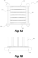
- FIG. 1A and 1B are schematic drawings showing an application example of the cushioning sheet according to Embodiment 1 of the present invention.
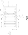
- FIG. 2 is a plan view of the cushioning sheet according to Embodiment 1 of the present invention.
- FIG. 3A and 3B are side views of the cushioning sheet according to Embodiment 1 of the present invention, where FIG. 3A is a view seen in the V1 direction in FIG. 2 , and FIG. 3B is a view seen in the V2 direction in FIG. 2 .
- FIGS. 1A and 1B are schematic drawings showing an application example of the cushioning sheet according to Embodiment 1 of the present invention.
- FIG. 2 is a plan view of the cushioning sheet according to Embodiment 1 of the present invention.
- FIG. 3A and 3B are side views of the cushioning sheet according to Embodiment 1 of the present invention, where FIG. 3A is a view seen in the V1 direction in FIG. 2 , and FIG. 3B is a view seen in the V2
- FIG. 4A and 4B are schematic cross-sectional views of the cushioning sheet according to Embodiment 1 of the present invention, where FIG. 4A is a cross-sectional view taken along the A1-A1 line in FIG. 2 , and FIG. 4B is a cross-sectional view taken along the A2-A2 line in FIG. 2 .
- FIG. 5A to 5D are explanatory drawings of the protruding portion according to Embodiment 1 of the present invention.
- FIG. 1A illustrates a case where the cushioning sheet 100 is applied to a battery 10.
- the battery 10 has a cell stack in which a plurality of unit cells 210 is stacked. The cell stack is compressed by a pair of clamping plates 221 and 222. The pair of clamping plates 221 and 222 are fastened by bolts 231 and nuts 232, so that a predetermined compressive force acts on the cell stack.
- a cushioning sheet 100 is provided between the clamping plate 221 and the cell stack, between adjacent unit cells 210, and between the cell stack and the clamping plate 222. This allows an appropriate pressing force to be applied to each unit cell 210 even when the unit cell 210 expands and contracts due to charging and discharging. This prevents the battery 10 from deteriorating and extends the service life of the battery 10.
- FIG. 1B shows a configuration in which a cushioning sheet 100 is provided between a base 310 and an item 320. This prevents the transmission of vibration to the item 320 even if the base 310 vibrates. In addition, even if the base 310 receives an impact, the impact is absorbed by the cushioning sheet 100, so that the item 320 can be protected from the impact.
- the cushioning sheet 100 has an elastic body and can be configured of an elastomer material (e.g., rubber).
- the cushioning sheet 100 has a flat plate 110 and a plurality of protruding portions 120 protruding from the flat plate 110.
- the plurality of protruding portions 120 are provided in six locations so as to be aligned in a row at equal intervals, but the arrangement and number of the protruding portions 120 are not particularly limited and may be set according to the overall dimensions and shape of the cushioning sheet 100 and the environment in which the cushioning sheet is to be used.
- Each protruding portion 120 is configured so that interior thereof is a cavity that opens in the opposite direction to the protrusion direction (see a cavity 120X in FIGS. 4A and 4B ).
- the opening in the cavity 120X of the cushioning sheet 100 configured as described above may be blocked by a member arranged on the opposite side to the protrusion direction of the protruding portion 120 depending on the usage environment, and the cavity 120X may become a sealed space.
- a communication groove 124 may be provided on the bottom surface of the flat plate 110 to connect the space of the cavity 120X with the outside space. This prevents the cavity 120X from becoming a sealed space.
- the protruding portion 120 includes a side part having two pairs of flat plate-shaped portions in which the distance between the opposing surfaces decreases toward the tips in the protrusion direction, and a curved plate-shaped portion 123 that connects the tips of the two pairs of flat plate-shaped portions.
- the side part has a pair of flat plate-shaped portions 121a and 121b extending in the longitudinal direction and a pair of flat plate-shaped portions 122a and 122b extending in the lateral direction.
- the cushioning sheet 100 at least one of the inner surface and the outer surface of the protruding portion 120 is provided with a groove that serves as a deformation starting point when the protruding portion 120 is compressed and deformed.
- the groove may be provided around the entire circumference of the side part of the protruding portion 120.
- the groove may be provided in the pair of flat plate-shaped portions 121a and 121b and the pair of flat plate-shaped portions 122a and 122b. This feature will be described in more detail with reference to FIGS. 5A to 5D .
- the grooves are omitted in FIGS. 2 to 4A and 4B .
- FIGS. 5A and 5B are cross-sectional views illustrating the protruding portion 120 in which a groove 125 is provided on the inner surface thereof.
- FIG. 5A corresponds to a cross-sectional view of the protruding portion 120 in FIG. 4A in an enlarged scale
- FIG. 5B corresponds to a view of FIG. 4B in which the groove 125 is clearly shown.
- the groove 125 is provided around the entire circumference of the inner surface of the side part of the protruding portion 120.
- the groove 125 is provided so as to be continuously connected on the inner surfaces of the flat plate-shaped portions 121a, 121b, 122a, and 122b.
- the groove 125 is provided so as to extend parallel to the flat plate 110.
- FIGS. 5C and 5D are side views illustrating the protruding portion 120 in which a groove 126 is provided on the outer surface of the protruding portion 120.
- FIG. 5C corresponds to a side view of the protruding portion 120 in FIG. 3A in an enlarged scale
- FIG. 5D corresponds to a view of FIG. 3B in which the groove 126 is clearly shown.
- the groove 126 is provided around the entire circumference of the outer surface of the side part of the protruding portion 120.
- the groove 126 is provided so as to be continuously connected on the outer surfaces of the flat plate-shaped portions 121a, 121b, 122a, and 122b.
- the groove 126 is provided so as to extend parallel to the flat plate 110.
- the cushioning sheet 100 when the protruding portion 120 is compressed and deformed, deformation starts from the grooves 125 and 126. Therefore, it is possible to stabilize the orientation of the protruding portion 120 when it is deformed by compression. That is, in the case of a protruding portion without a groove, the strength of each part of the protruding portion is almost the same, so the part where deformation starts may differ depending on the dimensional tolerance of the protruding portion and the state of the protruding portion at the time of compression, and the orientation at the time of compression may become unstable.
- the strength of the parts where the grooves 125 and 126 are provided is lower than that of the other parts, so when the protruding portion 120 is compressed, deformation starts from the grooves 125 and 126. Therefore, the orientation of the protruding portion 120 when it is deformed by compression can be stabilized.
- the grooves 125 and 126 are provided not in the curved plate-shaped portion 123 but in the flat plate-shaped portions 121a, 121b, 122a, and 122b. This makes it possible to more reliably stabilize the orientation of the protruding portion 120 when it is deformed by compression. The reason for this will be explained in the example shown below.
- the grooves 125 and 126 are provided so as to extend parallel to the flat plate 110. This prevents the protruding portion 120 from tilting relative to the flat plate 110 when the protruding portion 120 is compressed.
- the protruding portion 120 be compressed perpendicular to the flat plate 110.
- the grooves 125 and 126 extending parallel to the flat plate 110 prevent the protruding portion 120 from tilting relative to the flat plate 110 when the protruding portion 120 is compressed. Note that, depending on the application example of the cushioning sheet 100, where it is desirable that the protruding portion 120 be compressed so as to tilt relative to the flat plate 110, a configuration in which the groove is tilted relative to the flat plate 110 can also be adopted.
- the protruding portion 120 has the following two functions.
- the first one is the stability of orientation when the protruding portion 120 is compressed.
- a compressive force acts on the protruding portion 120 in an ideal direction (in the above example, a direction perpendicular to the flat plate 110)
- the orientation of the protruding portion 120 can be stabilized.
- the compressive force acting on the protruding portion 120 may deviate from the ideal direction. Therefore, it is desirable that the orientation of the protruding portion 120 in the compressed state could be stabilized even in this case.
- the compressive force acting on the protruding portion 120 varies depending on the usage environment.
- the reaction force when the protruding portion 120 is compressed changes greatly in an environment where the compression amount changes greatly, the functions of the cushioning sheet 100 may not be fully exerted. Therefore, as the second function, it is desirable that the change in the reaction force of the protruding portion 120 be small in response to the change in the compression amount of the protruding portion 120. In a case where this change in the reaction force is small, the cushioning sheet 100 can be applied in different usage environments, which also increases versatility.
- Example 1 relates to a configuration in which the groove 125 is provided on the inner surface of the protruding portion 120
- Example 2 relates to a configuration in which the groove 126 is provided on the outer surface of the protruding portion 120.
- FIGS. 6A to 6G to 8 are explanatory drawings of the protruding portions according to Example 1 of the present invention.
- FIGS. 6A to 6G are schematic cross-sectional views showing the state of the protruding portions when no compressive force is applied.
- FIGS. 7A to 7F are schematic cross-sectional views showing the state of the protruding portions when a compressive force is applied obliquely.
- FIG. 8 is a graph showing the relationship between the compression amount of the protruding portions and the reaction force.
- FIGS. 6A and 6B show the configurations of the protruding portions 120 described in the above embodiment when a groove is provided on the inner surface of the curved plate-shaped portion 123.
- Configuration 1 a linear groove 125a is provided at the very tip (top end in the figure) of the inner surface of the curved plate-shaped portion 123, so as to run along the pair of flat plate-shaped portions 121a and 121b.
- an annular groove 125b is provided near the base (near the bottom end in the figure) of the inner surface of the curved plate-shaped portion 123, so as to run along the pair of flat plate-shaped portions 121a and 121b and the pair of flat plate-shaped portions 122a and 122b.
- FIGS. 6C, 6D, 6E, 6F, and 6G show the configurations of the protruding portions 120 described in the above embodiment, in which the groove 125 is provided so as to be continuously connected on the inner surfaces of the flat plate-shaped portions 121a, 121b, 122a, and 122b.
- Configuration 3 Configuration 4, Configuration 5, Configuration 6, and Configuration 7, respectively.
- Configuration 3 a groove 125c is provided on the inner surfaces of the flat plate-shaped portions near the tips (upper ends in the figure) of the flat plate-shaped portions in the protrusion direction.
- a groove 125d is provided on the inner surfaces of the flat plate-shaped portions at a position between the center position along the length of the flat plate-shaped portions in the protrusion direction and the tip in the protrusion direction.
- a groove 125e is provided on the inner surfaces of the flat plate-shaped portions at the center position along the length of the flat plate-shaped portions in the protrusion direction.
- a groove 125f is provided on the inner surfaces of the flat plate-shaped portions at a position between the center position along the length of the flat plate-shaped portions in the protrusion direction and the boundary with the flat plate 110.
- a groove 125g is provided on the inner surfaces of the flat plate-shaped portions near the boundary with the flat plate 110.
- FIGS. 7A to 7F show the state of the protruding portions 120 when a compressive force acts obliquely on the protruding portions 120.
- FIG. 7A shows, as a reference example, the state of the protruding portion 120 when the groove 125 is not provided.
- FIG. 7B illustrates Configuration 2
- FIG. 7C illustrates Configuration 3
- FIG. 7D illustrates Configuration 4
- FIG. 7E illustrates Configuration 5
- FIG. 7F illustrates Configuration 7. From these figures, it can be understood that when the groove 125 is not provided and when the groove 125 is provided on the inner surface of the curved plate-shaped portion 123, where a compressive force acts obliquely, the protruding portion 120 is greatly deformed and orientation thereof becomes unstable.
- the protruding portion 120 is in a slightly buckled state. In the other examples, it is understood that even if a compressive force acts obliquely, the protruding portion 120 can be prevented from being greatly deformed and the orientation of the protruding portion 120 can be stabilized.
- Configuration 1 the case of Configuration 1 is not specifically illustrated, the protruding portion behaves in the same manner as in FIGS. 7A and 7B .
- Configuration 6 is also not specifically illustrated, it is understood that the state is intermediate between that in FIG. 7E and that in FIG. 7F .
- the first function can be achieved by providing the groove 125 in the flat plate-shaped portions, but it is better to avoid a position near the tips of the flat plate-shaped portions in the protrusion direction.
- FIG. 8 shows the relationship between the compression amount of the protruding portion and the reaction force.
- Graphs L5a, L5b, L5c, L5d, L5e, L5f, and L5g in the figure correspond to Configurations 1, 2, 3, 4, 5, 6, and 7, respectively.
- graph L5h relates to a configuration (reference example) in which the groove 125 is not provided in the protruding portion 120. From these graphs, it can be understood that the same relationship is shown in Configurations 1 and 2. It is also confirmed that the reference example without the groove shows the same relationship as with Configuration 1 and Configuration 2. It is also understood that the range of compression amount in which the reaction force does not change much can be widened, particularly in Configurations 5, 6, and 7.
- the groove 125 may be provided within a range from the center position along the length of the flat plate-shaped portions in the protrusion direction to the flat plate 110.
- FIGS. 9A to 9G to 11 are explanatory drawings of the protruding portions according to Example 2 of the present invention.
- FIGS. 9A to 9G are schematic cross-sectional views showing the state of the protruding portions when no compressive force is applied.
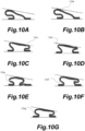
- FIGS. 10A to 10G are schematic cross-sectional views showing the state of the protruding portions when a compressive force is applied obliquely.
- FIG. 11 is a graph showing the relationship between the compression amount of the protruding portions and the reaction force.
- FIGS. 9A and 9B show the configurations of the protruding portions 120 described in the above embodiment when a groove is provided on the outer surface of the curved plate-shaped portion 123.
- Configuration 1 a linear groove 126a is provided at the very tip (top end in the figure) of the outer surface of the curved plate-shaped portion 123, so as to run along the pair of flat plate-shaped portions 121a and 121b.
- an annular groove 126b is provided near the base (near the bottom end in the figure) of the outer surface of the curved plate-shaped portion 123, so as to run along the pair of flat plate-shaped portions 121a and 121b and the pair of flat plate-shaped portions 122a and 122b.
- FIGS. 9C, 9D, 9E, 9F, and 9G show the configurations of the protruding portions 120 described in the above embodiment, in which the groove 126 is provided so as to be continuously connected on the outer surfaces of the flat plate-shaped portions 121a, 121b, 122a, and 122b.
- Configuration 3 Configuration 4, Configuration 5, Configuration 6, and Configuration 7, respectively.
- Configuration 3 a groove 126c is provided on the outer surfaces of the flat plate-shaped portions near the tips (upper ends in the figure) of the flat plate-shaped portions in the protrusion direction.
- a groove 126d is provided on the outer surfaces of the flat plate-shaped portions at a position between the center position along the length of the flat plate-shaped portions in the protrusion direction and the tip in the protrusion direction.
- a groove 126e is provided on the outer surfaces of the flat plate-shaped portions at the center position along the length of the flat plate-shaped portions in the protrusion direction.
- a groove 126f is provided on the outer surfaces of the flat plate-shaped portions at a position between the center position along the length of the flat plate-shaped portions in the protrusion direction and the boundary with the flat plate 110.
- a groove 126g is provided on the outer surfaces of the flat plate-shaped portions near the boundary with the flat plate 110.
- FIGS. 10A to 10G show the state of the protruding portions 120 when a compressive force acts obliquely on the protruding portions 120.
- FIG. 10A shows, as a reference example, the state of the protruding portion 120 when the groove 126 is not provided.
- FIG. 10B illustrates Configuration 2
- FIG. 10C illustrates Configuration 3
- FIG. 10D illustrates Configuration 4
- FIG. 10E illustrates Configuration 5
- FIG. 10F illustrates Configuration 6
- FIG. 10G illustrates Configuration 7.
- the first function can be achieved by providing the groove 126 in the flat plate-shaped portions, but it is better to avoid the center position along the length of the flat plate-shaped portions in the protrusion direction.
- FIG. 11 shows the relationship between the compression amount of the protruding portion and the reaction force.
- Graphs L6a, L6b, L6c, L6d, L6e, L6f, and L6g in the figure correspond to Configurations 1, 2, 3, 4, 5, 6, and 7, respectively.
- graph L6h relates to a configuration (reference example) in which the groove 126 is not provided in the protruding portion 120. From these graphs, it can be understood that the same relationship is shown in Configurations 1 and 2. It is also confirmed that the reference example without the groove shows the same relationship as in Configuration 1 and Configuration 2. It is also understood that the range of compression amount in which the reaction force does not change much can be widened, particularly in Configurations 6 and 7.
- the groove 126 may be provided within a range from the center position along the length of the flat plate-shaped portions in the protrusion direction to the flat plate 110.
- FIGS. 12A and 12B are external views of the cushioning sheet according to Embodiment 2 of the present invention, where FIG. 12A is a plan view and FIG. 12B is a side view (view seen in the V3 direction in FIG. 12A ).
- a cushioning sheet 100A according to the present embodiment can also be applied to the battery 10 or placed between a base 310 and an item 320 as described in Embodiment 1 with reference to FIGS. 1A to 1B .
- the cushioning sheet 100A has an elastic body and can be configured of an elastomer material (e.g., rubber).
- the cushioning sheet 100A has a flat plate 110A and a plurality of protruding portions 120A protruding from the flat plate 110A.
- the plurality of protruding portions 120A are provided in six locations so as to be aligned in a row at equal intervals, but the arrangement and number of the protruding portions 120A are not particularly limited and may be set according to the overall dimensions and shape of the cushioning sheet 100A and the environment in which the cushioning sheet is used.
- Each protruding portion 120A is configured so that the interior thereof is a cavity that opens in the opposite direction to the protrusion direction.
- the internal cavities of the protruding portions 120A of the cushioning sheet 100A according to the present embodiment are also open to the sides, so that in the above-mentioned application example, the cavities do not become sealed spaces.
- the protruding portion 120A is composed of a pair of flat plate-shaped portions 121Aa and 121Ab in which the distance between the opposing surfaces decreases toward the tips in the protrusion direction, and a curved plate-shaped portion 123A connecting the tips of the pair of flat plate-shaped portions 121Aa and 121Ab.
- a groove that serves as a deformation starting point when the protruding portion 120A is compressed and deformed can be provided on at least one of the inner surface and the outer surface of the protruding portion 120A, as in the above-described Embodiment 1.
- a linear groove may be provided on at least one of the inner surfaces and the outer surfaces of the pair of flat plate-shaped portions 121Aa and 121Ab.
- the configuration and arrangement of the grooves are as described in Examples 1 and 2, so the description thereof will be omitted.
- the groove that serves as a deformation starting point when the protruding portion is compressed is provided only on the inner or outer surface of the protruding portion, but it is also possible to adopt a configuration in which grooves are provided on both the inner and outer surfaces. Also, in the above examples, one groove is provided on the inner surface and one groove is provided on the outer surface, but two or more grooves may be provided on the inner surface, and two or more grooves may be provided on the outer surface.
Landscapes
- Engineering & Computer Science (AREA)
- General Engineering & Computer Science (AREA)
- Mechanical Engineering (AREA)
- Health & Medical Sciences (AREA)
- Child & Adolescent Psychology (AREA)
- Vibration Dampers (AREA)
- Buffer Packaging (AREA)
- Vibration Prevention Devices (AREA)
- Springs (AREA)
Abstract
A cushioning sheet (100, 100A) having an elastic body and including a flat plate (110, 110A), and a plurality of protruding portions (120, 120A) that protrudes from the flat plate, an interior of each protruding portion being a cavity (120X) that opens in an opposite direction to a protrusion direction, wherein at least one of an inner surface and an outer surface of the protruding portion is provided with a groove (125, 126) that serves as a deformation starting point when the protruding portion is compressed and deformed.
Description
- The present invention relates to a cushioning sheet.
- A cushioning sheet has been known that is placed between a base and an item to be loaded on the base so as to suppress the transmission of vibration to the item loaded on the base. This cushioning sheet is made of an elastic body and generates an elastic reaction force against the load acting from the item. Taking advantage of such properties, cushioning sheets have been used in recent years to suppress the deterioration of cells such as lithium-ion batteries. For example, the problem with lithium-ion batteries is that needle-shaped crystals (dendrites) of lithium metal are generated in repeated charging and discharging of the batteries. Continuous growth of such crystals results in a short circuit between the positive electrode and negative electrode. In addition, it is known that in all-solid-state batteries, variations in surface pressure due to expansion and contraction cause variations in performance and also affect the battery life. Therefore, measures have been taken to suppress cell expansion by applying an appropriate force to the cell, or to mechanically suppress the growth of the crystals in lithium-ion batteries.
- In order to generate the desired reaction force in a cushioning sheet, the cushioning sheet needs to be compressed to set a compression amount to be within a predetermined range. In the case of a flat cushioning sheet, the reaction force increases rapidly as the compression amount increases.
- Accordingly, it is known to provide a plurality of protruding portions, but even in this case, there is a limit to suppressing the rapid increase in reaction force that occurs with an increase in the compression amount, so it is also known to make the inside of the protruding portions hollow. However, with such techniques, the protruding portions may not maintain the desired orientation when compressed, hence the desired reaction force may not be generated. The related technique is described in
Japanese Patent No. 7165760 - The present invention provides a cushioning sheet that can generate a stable reaction force.
- The present invention employs the following means to solve the above problems.
- That is, the cushioning sheet of the present invention having an elastic body, the cushioning sheet comprising
- a flat plate, and
- a plurality of protruding portions that protrudes from the flat plate, an interior of each protruding portion being a cavity that opens in the opposite direction to a protrusion direction, wherein
- at least one of an inner surface and an outer surface of the protruding portion is provided with a groove that serves as a deformation starting point when the protruding portion is compressed and deformed.
- According to the present invention, when the protruding portion is compressed and deformed, the deformation starts from the groove, so that it is possible to stabilize the orientation when the protruding portion is deformed by compression.
- The protruding portion may include
- a pair of flat plate-shaped portions in which a distance between opposing surfaces thereof decreases toward tips in the protrusion direction, and
- a curved plate-shaped portion that connects the tips of the pair of flat plate-shaped portions, and
- the groove may be provided in the flat plate-shaped portions.
- By adopting such a configuration, the orientation of the protruding portion that is deformed by compression can be stabilized more reliably.
- The protruding portion may include a side part having two pairs of flat plate-shaped portions in which a distance between opposing surfaces thereof decreases toward the tips in the protrusion direction, and a curved plate-shaped portion that connects the tips of the two pairs of flat plate-shaped portions, and
the groove may be provided along an entire circumference of the side part. - By adopting such a configuration, the orientation of the protruding portion that is deformed by compression can be stabilized more reliably.
- The groove may be provided so as to extend parallel to the flat plate.
- This prevents the protruding portion from tilting relative to the flat plate when the protruding portion is compressed.
- The groove may be provided on the inner surface within a range from a center position of a length of the flat plate-shaped portions in the protrusion direction to the flat plate.
- The groove may be provided on the outer surface within a range from a center position of a length of the flat plate-shaped portions in the protrusion direction to the flat plate.
- The above features may be combined to the extent possible.
- As described above, according to the present invention, a reaction force can be generated stably.
-
-
FIGS. 1A and 1B are schematic drawings showing an application example of a cushioning sheet according toEmbodiment 1 of the present invention; -
FIG. 2 is a plan view of the cushioning sheet according toEmbodiment 1 of the present invention; -
FIGS. 3A and 3B are side views of the cushioning sheet according toEmbodiment 1 of the present invention; -
FIGS. 4A and 4B are schematic cross-sectional views of the cushioning sheet according toEmbodiment 1 of the present invention; -
FIGS. 5A to 5D are explanatory drawings of protruding portions according toEmbodiment 1 of the present invention; -
FIGS. 6A to 6G are explanatory drawings of protruding portions according to Example 1 of the present invention; -
FIGS. 7A to 7F are explanatory drawings of protruding portions according to Example 1 of the present invention; -
FIG. 8 is an explanatory drawing relating to protruding portions according to Example 1 of the present invention; -
FIGS. 9A to 9G are explanatory drawings of protruding portions according to Example 2 of the present invention; -
FIGS. 10A to 10G are explanatory drawings of protruding portions according to Example 2 of the present invention; -
FIGS. 11 is an explanatory drawing relating to protruding portions according to Example 2 of the present invention; and -
FIGS. 12A and 12B are external views of the cushioning sheet according toEmbodiment 2 of the present invention. - A mode for carrying out the present invention will be described hereinbelow in detail based on the embodiments and examples with reference to the drawings. However, the dimensions, materials, shapes, relative positions, etc. of the components described in the examples are not intended to limit the scope of the present invention unless otherwise specified.
- The cushioning sheet according to
Embodiment 1 of the present invention will be described with reference toFIGS. 1A and 1B to 5A to 5D .FIG. 1A and 1B are schematic drawings showing an application example of the cushioning sheet according toEmbodiment 1 of the present invention.FIG. 2 is a plan view of the cushioning sheet according toEmbodiment 1 of the present invention.FIG. 3A and 3B are side views of the cushioning sheet according toEmbodiment 1 of the present invention, whereFIG. 3A is a view seen in the V1 direction inFIG. 2 , andFIG. 3B is a view seen in the V2 direction inFIG. 2 .FIGS. 4A and 4B are schematic cross-sectional views of the cushioning sheet according toEmbodiment 1 of the present invention, whereFIG. 4A is a cross-sectional view taken along the A1-A1 line inFIG. 2 , andFIG. 4B is a cross-sectional view taken along the A2-A2 line inFIG. 2 .FIG. 5A to 5D are explanatory drawings of the protruding portion according toEmbodiment 1 of the present invention. - An application example of a
cushioning sheet 100 will be described with reference toFIGS. 1A and 1B. FIG. 1A illustrates a case where thecushioning sheet 100 is applied to abattery 10. Thebattery 10 has a cell stack in which a plurality ofunit cells 210 is stacked. The cell stack is compressed by a pair of clampingplates plates bolts 231 andnuts 232, so that a predetermined compressive force acts on the cell stack. In thebattery 10 according to this embodiment, acushioning sheet 100 is provided between the clampingplate 221 and the cell stack, betweenadjacent unit cells 210, and between the cell stack and theclamping plate 222. This allows an appropriate pressing force to be applied to eachunit cell 210 even when theunit cell 210 expands and contracts due to charging and discharging. This prevents thebattery 10 from deteriorating and extends the service life of thebattery 10. -
FIG. 1B shows a configuration in which acushioning sheet 100 is provided between a base 310 and anitem 320. This prevents the transmission of vibration to theitem 320 even if the base 310 vibrates. In addition, even if thebase 310 receives an impact, the impact is absorbed by thecushioning sheet 100, so that theitem 320 can be protected from the impact. - The
cushioning sheet 100 according to this embodiment will be described with reference toFIGS. 2 to 5A to 5D . Thecushioning sheet 100 has an elastic body and can be configured of an elastomer material (e.g., rubber). Thecushioning sheet 100 has aflat plate 110 and a plurality of protrudingportions 120 protruding from theflat plate 110. In the example shown inFIG. 2 , the plurality of protrudingportions 120 are provided in six locations so as to be aligned in a row at equal intervals, but the arrangement and number of the protrudingportions 120 are not particularly limited and may be set according to the overall dimensions and shape of thecushioning sheet 100 and the environment in which the cushioning sheet is to be used. Each protrudingportion 120 is configured so that interior thereof is a cavity that opens in the opposite direction to the protrusion direction (see acavity 120X inFIGS. 4A and 4B ). - The opening in the
cavity 120X of thecushioning sheet 100 configured as described above may be blocked by a member arranged on the opposite side to the protrusion direction of the protrudingportion 120 depending on the usage environment, and thecavity 120X may become a sealed space. In this case, when the protrudingportion 120 is compressed, the air in the cavity cannot escape to the outside, and the reaction force becomes higher than expected. Therefore, depending on the usage environment, acommunication groove 124 may be provided on the bottom surface of theflat plate 110 to connect the space of thecavity 120X with the outside space. This prevents thecavity 120X from becoming a sealed space. However, where a passage for releasing the air in the cavity is formed on a member arranged on the opposite side to the protrusion direction of the protrudingportion 120, it is not necessary to provide theabovementioned communication groove 124. Thecommunication groove 124 may not needed when thecavity 120X becoming a sealed space is not a problem. - The protruding
portion 120 according to this embodiment includes a side part having two pairs of flat plate-shaped portions in which the distance between the opposing surfaces decreases toward the tips in the protrusion direction, and a curved plate-shapedportion 123 that connects the tips of the two pairs of flat plate-shaped portions. The side part has a pair of flat plate-shapedportions portions - In the
cushioning sheet 100 according to the present embodiment, at least one of the inner surface and the outer surface of the protrudingportion 120 is provided with a groove that serves as a deformation starting point when the protrudingportion 120 is compressed and deformed. The groove may be provided around the entire circumference of the side part of the protrudingportion 120. In other words, the groove may be provided in the pair of flat plate-shapedportions portions FIGS. 5A to 5D . The grooves are omitted inFIGS. 2 to 4A and4B . -
FIGS. 5A and 5B are cross-sectional views illustrating the protrudingportion 120 in which agroove 125 is provided on the inner surface thereof.FIG. 5A corresponds to a cross-sectional view of the protrudingportion 120 inFIG. 4A in an enlarged scale, andFIG. 5B corresponds to a view ofFIG. 4B in which thegroove 125 is clearly shown. As shown in these figures, thegroove 125 is provided around the entire circumference of the inner surface of the side part of the protrudingportion 120. In other words, thegroove 125 is provided so as to be continuously connected on the inner surfaces of the flat plate-shapedportions groove 125 is provided so as to extend parallel to theflat plate 110. -
FIGS. 5C and 5D are side views illustrating the protrudingportion 120 in which agroove 126 is provided on the outer surface of the protrudingportion 120.FIG. 5C corresponds to a side view of the protrudingportion 120 inFIG. 3A in an enlarged scale, andFIG. 5D corresponds to a view ofFIG. 3B in which thegroove 126 is clearly shown. As shown in these figures, thegroove 126 is provided around the entire circumference of the outer surface of the side part of the protrudingportion 120. In other words, thegroove 126 is provided so as to be continuously connected on the outer surfaces of the flat plate-shapedportions groove 126 is provided so as to extend parallel to theflat plate 110. - With the
cushioning sheet 100 according to the present embodiment, when the protrudingportion 120 is compressed and deformed, deformation starts from thegrooves portion 120 when it is deformed by compression. That is, in the case of a protruding portion without a groove, the strength of each part of the protruding portion is almost the same, so the part where deformation starts may differ depending on the dimensional tolerance of the protruding portion and the state of the protruding portion at the time of compression, and the orientation at the time of compression may become unstable. In contrast, as in the present embodiment where thegrooves grooves portion 120 is compressed, deformation starts from thegrooves portion 120 when it is deformed by compression can be stabilized. - In the present embodiment, the
grooves portion 123 but in the flat plate-shapedportions portion 120 when it is deformed by compression. The reason for this will be explained in the example shown below. - In addition, in the present embodiment, the
grooves flat plate 110. This prevents the protrudingportion 120 from tilting relative to theflat plate 110 when the protrudingportion 120 is compressed. In the case of the application example of thecushioning sheet 100 described with reference toFIGS. 1A and 1B , it is desirable that the protrudingportion 120 be compressed perpendicular to theflat plate 110. As described above, thegrooves flat plate 110 prevent the protrudingportion 120 from tilting relative to theflat plate 110 when the protrudingportion 120 is compressed. Note that, depending on the application example of thecushioning sheet 100, where it is desirable that the protrudingportion 120 be compressed so as to tilt relative to theflat plate 110, a configuration in which the groove is tilted relative to theflat plate 110 can also be adopted. - The protruding
portion 120 has the following two functions. - The first one, as described hereinabove, is the stability of orientation when the protruding
portion 120 is compressed. When a compressive force acts on the protrudingportion 120 in an ideal direction (in the above example, a direction perpendicular to the flat plate 110), the orientation of the protrudingportion 120 can be stabilized. However, depending on the usage environment, the compressive force acting on the protrudingportion 120 may deviate from the ideal direction. Therefore, it is desirable that the orientation of the protrudingportion 120 in the compressed state could be stabilized even in this case. - In addition, the compressive force acting on the protruding
portion 120 varies depending on the usage environment. In a case where the reaction force when the protrudingportion 120 is compressed changes greatly in an environment where the compression amount changes greatly, the functions of thecushioning sheet 100 may not be fully exerted. Therefore, as the second function, it is desirable that the change in the reaction force of the protrudingportion 120 be small in response to the change in the compression amount of the protrudingportion 120. In a case where this change in the reaction force is small, thecushioning sheet 100 can be applied in different usage environments, which also increases versatility. - The above two functions are influenced by various parameters. However, the inventors of the present application have found that the above two functions are largely dependent on the arrangement positions of the
grooves grooves groove 125 is provided on the inner surface of the protrudingportion 120, and Example 2 relates to a configuration in which thegroove 126 is provided on the outer surface of the protrudingportion 120. - The configurations of the protruding portions according to Example 1 of the present invention will be explained with reference to
FIGS. 6A to 6G to 8. FIGS. 6A to 6G to 8 are explanatory drawings of the protruding portions according to Example 1 of the present invention.FIGS. 6A to 6G are schematic cross-sectional views showing the state of the protruding portions when no compressive force is applied.FIGS. 7A to 7F are schematic cross-sectional views showing the state of the protruding portions when a compressive force is applied obliquely.FIG. 8 is a graph showing the relationship between the compression amount of the protruding portions and the reaction force. -
FIGS. 6A and 6B show the configurations of the protrudingportions 120 described in the above embodiment when a groove is provided on the inner surface of the curved plate-shapedportion 123. Hereinafter, these are referred to asConfiguration 1 andConfiguration 2, respectively. InConfiguration 1, alinear groove 125a is provided at the very tip (top end in the figure) of the inner surface of the curved plate-shapedportion 123, so as to run along the pair of flat plate-shapedportions Configuration 2, anannular groove 125b is provided near the base (near the bottom end in the figure) of the inner surface of the curved plate-shapedportion 123, so as to run along the pair of flat plate-shapedportions portions -
FIGS. 6C, 6D, 6E, 6F, and 6G show the configurations of the protrudingportions 120 described in the above embodiment, in which thegroove 125 is provided so as to be continuously connected on the inner surfaces of the flat plate-shapedportions Configuration 4, Configuration 5,Configuration 6, and Configuration 7, respectively. In Configuration 3, agroove 125c is provided on the inner surfaces of the flat plate-shaped portions near the tips (upper ends in the figure) of the flat plate-shaped portions in the protrusion direction. InConfiguration 4, agroove 125d is provided on the inner surfaces of the flat plate-shaped portions at a position between the center position along the length of the flat plate-shaped portions in the protrusion direction and the tip in the protrusion direction. In Configuration 5, agroove 125e is provided on the inner surfaces of the flat plate-shaped portions at the center position along the length of the flat plate-shaped portions in the protrusion direction. InConfiguration 6, agroove 125f is provided on the inner surfaces of the flat plate-shaped portions at a position between the center position along the length of the flat plate-shaped portions in the protrusion direction and the boundary with theflat plate 110. In Configuration 7, agroove 125g is provided on the inner surfaces of the flat plate-shaped portions near the boundary with theflat plate 110. -
FIGS. 7A to 7F show the state of the protrudingportions 120 when a compressive force acts obliquely on the protrudingportions 120.FIG. 7A shows, as a reference example, the state of the protrudingportion 120 when thegroove 125 is not provided.FIG. 7B illustratesConfiguration 2,FIG. 7C illustrates Configuration 3,FIG. 7D illustratesConfiguration 4,FIG. 7E illustrates Configuration 5, andFIG. 7F illustrates Configuration 7. From these figures, it can be understood that when thegroove 125 is not provided and when thegroove 125 is provided on the inner surface of the curved plate-shapedportion 123, where a compressive force acts obliquely, the protrudingportion 120 is greatly deformed and orientation thereof becomes unstable. Also, in the case ofConfiguration 2, it is understood that the protrudingportion 120 is in a slightly buckled state. In the other examples, it is understood that even if a compressive force acts obliquely, the protrudingportion 120 can be prevented from being greatly deformed and the orientation of the protrudingportion 120 can be stabilized. Although the case ofConfiguration 1 is not specifically illustrated, the protruding portion behaves in the same manner as inFIGS. 7A and 7B . Although the case ofConfiguration 6 is also not specifically illustrated, it is understood that the state is intermediate between that inFIG. 7E and that inFIG. 7F . From the above, it can be understood that, of the two desired functions of the protrudingportion 120 described above, the first function can be achieved by providing thegroove 125 in the flat plate-shaped portions, but it is better to avoid a position near the tips of the flat plate-shaped portions in the protrusion direction. -
FIG. 8 shows the relationship between the compression amount of the protruding portion and the reaction force. Graphs L5a, L5b, L5c, L5d, L5e, L5f, and L5g in the figure correspond toConfigurations groove 125 is not provided in the protrudingportion 120. From these graphs, it can be understood that the same relationship is shown inConfigurations Configuration 1 andConfiguration 2. It is also understood that the range of compression amount in which the reaction force does not change much can be widened, particularly inConfigurations 5, 6, and 7. From the above, it can be understood that, for the second of the two desired functions of the protrudingportion 120 described above, thegroove 125 may be provided within a range from the center position along the length of the flat plate-shaped portions in the protrusion direction to theflat plate 110. - The configurations of the protruding portions according to Example 2 of the present invention will be explained with reference to
FIGS. 9A to 9G to 11. FIGS. 9A to 9G to 11 are explanatory drawings of the protruding portions according to Example 2 of the present invention.FIGS. 9A to 9G are schematic cross-sectional views showing the state of the protruding portions when no compressive force is applied.FIGS. 10A to 10G are schematic cross-sectional views showing the state of the protruding portions when a compressive force is applied obliquely.FIG. 11 is a graph showing the relationship between the compression amount of the protruding portions and the reaction force. -
FIGS. 9A and 9B show the configurations of the protrudingportions 120 described in the above embodiment when a groove is provided on the outer surface of the curved plate-shapedportion 123. Hereinafter, these are referred to asConfiguration 1 andConfiguration 2, respectively. InConfiguration 1, alinear groove 126a is provided at the very tip (top end in the figure) of the outer surface of the curved plate-shapedportion 123, so as to run along the pair of flat plate-shapedportions Configuration 2, anannular groove 126b is provided near the base (near the bottom end in the figure) of the outer surface of the curved plate-shapedportion 123, so as to run along the pair of flat plate-shapedportions portions -
FIGS. 9C, 9D, 9E, 9F, and 9G show the configurations of the protrudingportions 120 described in the above embodiment, in which thegroove 126 is provided so as to be continuously connected on the outer surfaces of the flat plate-shapedportions Configuration 4, Configuration 5,Configuration 6, and Configuration 7, respectively. In Configuration 3, agroove 126c is provided on the outer surfaces of the flat plate-shaped portions near the tips (upper ends in the figure) of the flat plate-shaped portions in the protrusion direction. InConfiguration 4, agroove 126d is provided on the outer surfaces of the flat plate-shaped portions at a position between the center position along the length of the flat plate-shaped portions in the protrusion direction and the tip in the protrusion direction. In Configuration 5, agroove 126e is provided on the outer surfaces of the flat plate-shaped portions at the center position along the length of the flat plate-shaped portions in the protrusion direction. InConfiguration 6, agroove 126f is provided on the outer surfaces of the flat plate-shaped portions at a position between the center position along the length of the flat plate-shaped portions in the protrusion direction and the boundary with theflat plate 110. In Configuration 7, agroove 126g is provided on the outer surfaces of the flat plate-shaped portions near the boundary with theflat plate 110. -
FIGS. 10A to 10G show the state of the protrudingportions 120 when a compressive force acts obliquely on the protrudingportions 120.FIG. 10A shows, as a reference example, the state of the protrudingportion 120 when thegroove 126 is not provided.FIG. 10B illustratesConfiguration 2,FIG. 10C illustrates Configuration 3,FIG. 10D illustratesConfiguration 4,FIG. 10E illustrates Configuration 5,FIG. 10F illustratesConfiguration 6, andFIG. 10G illustrates Configuration 7. From these figures, it can be understood that when thegroove 126 is not provided and when thegroove 126 is provided on the outer surface of the curved plate-shapedportion 123, where a compressive force acts obliquely, the protrudingportion 120 is greatly deformed and orientation thereof becomes unstable. Also, in the case of Configuration 5, it is understood that slight buckling occurs. In the other examples, it is understood that even if a compressive force acts obliquely, the protrudingportion 120 can be prevented from being greatly deformed and the orientation of the protrudingportion 120 can be stabilized. Although the case ofConfiguration 1 is not specifically illustrated, the protruding portion behaves in the same manner as inFIGS. 10A and 10B . From the above, it can be understood that, of the two desired functions of the protrudingportion 120 described above, the first function can be achieved by providing thegroove 126 in the flat plate-shaped portions, but it is better to avoid the center position along the length of the flat plate-shaped portions in the protrusion direction. -
FIG. 11 shows the relationship between the compression amount of the protruding portion and the reaction force. Graphs L6a, L6b, L6c, L6d, L6e, L6f, and L6g in the figure correspond toConfigurations groove 126 is not provided in the protrudingportion 120. From these graphs, it can be understood that the same relationship is shown inConfigurations Configuration 1 andConfiguration 2. It is also understood that the range of compression amount in which the reaction force does not change much can be widened, particularly inConfigurations 6 and 7. From the above, it can be understood that, for the second of the two desired functions of the protrudingportion 120 described above, thegroove 126 may be provided within a range from the center position along the length of the flat plate-shaped portions in the protrusion direction to theflat plate 110. - The cushioning sheet according to
Embodiment 2 of the present invention will be described with reference toFIGS. 12A and 12B. FIGS. 12A and 12B are external views of the cushioning sheet according toEmbodiment 2 of the present invention, whereFIG. 12A is a plan view andFIG. 12B is a side view (view seen in the V3 direction inFIG. 12A ). - A
cushioning sheet 100A according to the present embodiment can also be applied to thebattery 10 or placed between a base 310 and anitem 320 as described inEmbodiment 1 with reference toFIGS. 1A to 1B . - The
cushioning sheet 100A according to the present embodiment has an elastic body and can be configured of an elastomer material (e.g., rubber). Thecushioning sheet 100A has aflat plate 110A and a plurality of protrudingportions 120A protruding from theflat plate 110A. In the example shown in the figure, the plurality of protrudingportions 120A are provided in six locations so as to be aligned in a row at equal intervals, but the arrangement and number of the protrudingportions 120A are not particularly limited and may be set according to the overall dimensions and shape of thecushioning sheet 100A and the environment in which the cushioning sheet is used. Each protrudingportion 120A is configured so that the interior thereof is a cavity that opens in the opposite direction to the protrusion direction. The internal cavities of the protrudingportions 120A of thecushioning sheet 100A according to the present embodiment are also open to the sides, so that in the above-mentioned application example, the cavities do not become sealed spaces. - The protruding
portion 120A according to the present embodiment is composed of a pair of flat plate-shaped portions 121Aa and 121Ab in which the distance between the opposing surfaces decreases toward the tips in the protrusion direction, and a curved plate-shapedportion 123A connecting the tips of the pair of flat plate-shaped portions 121Aa and 121Ab. - In the
cushioning sheet 100A configured as above, a groove that serves as a deformation starting point when the protrudingportion 120A is compressed and deformed can be provided on at least one of the inner surface and the outer surface of the protrudingportion 120A, as in the above-describedEmbodiment 1. In the present embodiment, a linear groove may be provided on at least one of the inner surfaces and the outer surfaces of the pair of flat plate-shaped portions 121Aa and 121Ab. The configuration and arrangement of the grooves are as described in Examples 1 and 2, so the description thereof will be omitted. - By adopting the above configurations, it is possible to obtain the same effects as in
Embodiment 1 and Examples 1 and 2. - In the above examples, the groove that serves as a deformation starting point when the protruding portion is compressed is provided only on the inner or outer surface of the protruding portion, but it is also possible to adopt a configuration in which grooves are provided on both the inner and outer surfaces. Also, in the above examples, one groove is provided on the inner surface and one groove is provided on the outer surface, but two or more grooves may be provided on the inner surface, and two or more grooves may be provided on the outer surface.
Claims (6)
- A cushioning sheet having an elastic body, the cushioning sheet comprising:a flat plate, anda plurality of protruding portions that protrudes from the flat plate, an interior of each protruding portion being a cavity that opens in an opposite direction to a protrusion direction, whereinat least one of an inner surface and an outer surface of the protruding portion is provided with a groove that serves as a deformation starting point when the protruding portion is compressed and deformed.
- The cushioning sheet according to claim 1, whereinthe protruding portion includesa pair of flat plate-shaped portions in which a distance between opposing surfaces thereof decreases toward tips in the protrusion direction, anda curved plate-shaped portion that connects the tips of the pair of flat plate-shaped portions, andthe groove is provided in the flat plate-shaped portions.
- The cushioning sheet according to claim 1, whereinthe protruding portion includes a side part having two pairs of flat plate-shaped portions in which a distance between opposing surfaces thereof decreases toward tips in the protrusion direction, and a curved plate-shaped portion that connects the tips of the two pairs of flat plate-shaped portions, andthe groove is provided along an entire circumference of the side part.
- The cushioning sheet according to claim 2 or 3, wherein
the groove is provided so as to extend parallel to the flat plate. - The cushioning sheet according to claim 4, wherein
the groove is provided on the inner surface within a range from a center position of a length of the flat plate-shaped portions in the protrusion direction to the flat plate. - The cushioning sheet according to claim 4, wherein
the groove is provided on the outer surface within a range from a center position of a length of the flat plate-shaped portions in the protrusion direction to the flat plate.
Applications Claiming Priority (1)
| Application Number | Priority Date | Filing Date | Title |
|---|---|---|---|
| JP2023164106A JP2025054892A (en) | 2023-09-27 | 2023-09-27 | Cushioning Sheet |
Publications (1)
| Publication Number | Publication Date |
|---|---|
| EP4530492A1 true EP4530492A1 (en) | 2025-04-02 |
Family
ID=92925642
Family Applications (1)
| Application Number | Title | Priority Date | Filing Date |
|---|---|---|---|
| EP24202850.4A Pending EP4530492A1 (en) | 2023-09-27 | 2024-09-26 | Cushioning sheet |
Country Status (4)
| Country | Link |
|---|---|
| US (1) | US20250102039A1 (en) |
| EP (1) | EP4530492A1 (en) |
| JP (1) | JP2025054892A (en) |
| CN (1) | CN119712751A (en) |
Citations (3)
| Publication number | Priority date | Publication date | Assignee | Title |
|---|---|---|---|---|
| US20030127841A1 (en) * | 1998-11-21 | 2003-07-10 | Michael Ashmead | Energy-absorbing structure |
| JP2006192947A (en) * | 2005-01-11 | 2006-07-27 | Honda Motor Co Ltd | Anti-vibration support structure for vehicle parts |
| US20220082146A1 (en) * | 2019-02-15 | 2022-03-17 | Nok Corporation | Cushioning rubber, reaction force adjusting method thereof, and pedestal |
-
2023
- 2023-09-27 JP JP2023164106A patent/JP2025054892A/en active Pending
-
2024
- 2024-09-26 CN CN202411352302.5A patent/CN119712751A/en active Pending
- 2024-09-26 EP EP24202850.4A patent/EP4530492A1/en active Pending
- 2024-09-26 US US18/898,493 patent/US20250102039A1/en active Pending
Patent Citations (4)
| Publication number | Priority date | Publication date | Assignee | Title |
|---|---|---|---|---|
| US20030127841A1 (en) * | 1998-11-21 | 2003-07-10 | Michael Ashmead | Energy-absorbing structure |
| JP2006192947A (en) * | 2005-01-11 | 2006-07-27 | Honda Motor Co Ltd | Anti-vibration support structure for vehicle parts |
| US20220082146A1 (en) * | 2019-02-15 | 2022-03-17 | Nok Corporation | Cushioning rubber, reaction force adjusting method thereof, and pedestal |
| JP7165760B2 (en) | 2019-02-15 | 2022-11-04 | Nok株式会社 | Buffer rubber and its reaction force adjustment method and pedestal |
Non-Patent Citations (1)
| Title |
|---|
| ANONYMOUS: "Stress concentration - Wikipedia", 12 August 2023 (2023-08-12), pages - 5, XP093246992, Retrieved from the Internet <URL:https://en.wikipedia.org/w/index.php?title=Stress_concentration&oldid=1170039450> [retrieved on 20250205] * |
Also Published As
| Publication number | Publication date |
|---|---|
| US20250102039A1 (en) | 2025-03-27 |
| CN119712751A (en) | 2025-03-28 |
| JP2025054892A (en) | 2025-04-08 |
Similar Documents
| Publication | Publication Date | Title |
|---|---|---|
| US20200194753A1 (en) | Power storage device | |
| EP2421069B1 (en) | Battery module | |
| US20120088146A1 (en) | Rechargeable battery | |
| CN109962192B (en) | battery module | |
| EP3131137B1 (en) | Battery pack | |
| WO2019142645A1 (en) | Power storage device | |
| US8481201B2 (en) | Case for secondary battery and lithium secondary battery using the same | |
| KR102939993B1 (en) | Battery module case and battery module having the same | |
| US20090061294A1 (en) | Battery case and battery pack using the same | |
| WO2018101079A1 (en) | Secondary cell and cell pack | |
| US20230344053A1 (en) | Support structure | |
| WO2020134747A1 (en) | Battery module and battery pack | |
| EP3217450B1 (en) | Battery module | |
| JP7557527B2 (en) | Battery Module | |
| US20180175437A1 (en) | Battery | |
| US20250102039A1 (en) | Cushioning sheet | |
| EP3373360B1 (en) | Battery module | |
| KR20200077296A (en) | Battery Pack Housing Having Thickness Variation and Battery Pack Comprising the Same | |
| CN118645749A (en) | Battery Module | |
| CN223052300U (en) | Battery pack | |
| US20260074345A1 (en) | Battery assembly | |
| US20250055139A1 (en) | Battery module | |
| JP2026080694A (en) | Energy storage module | |
| JP7844292B2 (en) | All-solid-state battery assembly | |
| JP2026080695A (en) | Energy storage module |
Legal Events
| Date | Code | Title | Description |
|---|---|---|---|
| PUAI | Public reference made under article 153(3) epc to a published international application that has entered the european phase |
Free format text: ORIGINAL CODE: 0009012 |
|
| STAA | Information on the status of an ep patent application or granted ep patent |
Free format text: STATUS: REQUEST FOR EXAMINATION WAS MADE |
|
| 17P | Request for examination filed |
Effective date: 20240926 |
|
| AK | Designated contracting states |
Kind code of ref document: A1 Designated state(s): AL AT BE BG CH CY CZ DE DK EE ES FI FR GB GR HR HU IE IS IT LI LT LU LV MC ME MK MT NL NO PL PT RO RS SE SI SK SM TR |