EP4530436A2 - Flow control device formed of thermally adaptive material and a thermoelectric junction - Google Patents
Flow control device formed of thermally adaptive material and a thermoelectric junction Download PDFInfo
- Publication number
- EP4530436A2 EP4530436A2 EP24196240.6A EP24196240A EP4530436A2 EP 4530436 A2 EP4530436 A2 EP 4530436A2 EP 24196240 A EP24196240 A EP 24196240A EP 4530436 A2 EP4530436 A2 EP 4530436A2
- Authority
- EP
- European Patent Office
- Prior art keywords
- cte
- segment
- control device
- flow control
- outer boundary
- Prior art date
- Legal status (The legal status is an assumption and is not a legal conclusion. Google has not performed a legal analysis and makes no representation as to the accuracy of the status listed.)
- Pending
Links
Images




Classifications
-
- G—PHYSICS
- G05—CONTROLLING; REGULATING
- G05D—SYSTEMS FOR CONTROLLING OR REGULATING NON-ELECTRIC VARIABLES
- G05D7/00—Control of flow
- G05D7/06—Control of flow characterised by the use of electric means
- G05D7/0617—Control of flow characterised by the use of electric means specially adapted for fluid materials
- G05D7/0629—Control of flow characterised by the use of electric means specially adapted for fluid materials characterised by the type of regulator means
- G05D7/0635—Control of flow characterised by the use of electric means specially adapted for fluid materials characterised by the type of regulator means by action on throttling means
-
- F—MECHANICAL ENGINEERING; LIGHTING; HEATING; WEAPONS; BLASTING
- F01—MACHINES OR ENGINES IN GENERAL; ENGINE PLANTS IN GENERAL; STEAM ENGINES
- F01D—NON-POSITIVE DISPLACEMENT MACHINES OR ENGINES, e.g. STEAM TURBINES
- F01D17/00—Regulating or controlling by varying flow
- F01D17/10—Final actuators
- F01D17/12—Final actuators arranged in stator parts
- F01D17/14—Final actuators arranged in stator parts varying effective cross-sectional area of nozzles or guide conduits
-
- F—MECHANICAL ENGINEERING; LIGHTING; HEATING; WEAPONS; BLASTING
- F01—MACHINES OR ENGINES IN GENERAL; ENGINE PLANTS IN GENERAL; STEAM ENGINES
- F01D—NON-POSITIVE DISPLACEMENT MACHINES OR ENGINES, e.g. STEAM TURBINES
- F01D25/00—Component parts, details, or accessories, not provided for in, or of interest apart from, other groups
- F01D25/005—Selecting particular materials
-
- F—MECHANICAL ENGINEERING; LIGHTING; HEATING; WEAPONS; BLASTING
- F16—ENGINEERING ELEMENTS AND UNITS; GENERAL MEASURES FOR PRODUCING AND MAINTAINING EFFECTIVE FUNCTIONING OF MACHINES OR INSTALLATIONS; THERMAL INSULATION IN GENERAL
- F16K—VALVES; TAPS; COCKS; ACTUATING-FLOATS; DEVICES FOR VENTING OR AERATING
- F16K7/00—Diaphragm valves or cut-off apparatus, e.g. with a member deformed, but not moved bodily, to close the passage ; Pinch valves
- F16K7/02—Diaphragm valves or cut-off apparatus, e.g. with a member deformed, but not moved bodily, to close the passage ; Pinch valves with tubular diaphragm
- F16K7/04—Diaphragm valves or cut-off apparatus, e.g. with a member deformed, but not moved bodily, to close the passage ; Pinch valves with tubular diaphragm constrictable by external radial force
-
- H—ELECTRICITY
- H10—SEMICONDUCTOR DEVICES; ELECTRIC SOLID-STATE DEVICES NOT OTHERWISE PROVIDED FOR
- H10N—ELECTRIC SOLID-STATE DEVICES NOT OTHERWISE PROVIDED FOR
- H10N10/00—Thermoelectric devices comprising a junction of dissimilar materials, i.e. devices exhibiting Seebeck or Peltier effects
- H10N10/80—Constructional details
-
- B—PERFORMING OPERATIONS; TRANSPORTING
- B64—AIRCRAFT; AVIATION; COSMONAUTICS
- B64C—AEROPLANES; HELICOPTERS
- B64C3/00—Wings
- B64C3/38—Adjustment of complete wings or parts thereof
-
- B—PERFORMING OPERATIONS; TRANSPORTING
- B64—AIRCRAFT; AVIATION; COSMONAUTICS
- B64C—AEROPLANES; HELICOPTERS
- B64C9/00—Adjustable control surfaces or members, e.g. rudders
-
- F—MECHANICAL ENGINEERING; LIGHTING; HEATING; WEAPONS; BLASTING
- F05—INDEXING SCHEMES RELATING TO ENGINES OR PUMPS IN VARIOUS SUBCLASSES OF CLASSES F01-F04
- F05D—INDEXING SCHEME FOR ASPECTS RELATING TO NON-POSITIVE-DISPLACEMENT MACHINES OR ENGINES, GAS-TURBINES OR JET-PROPULSION PLANTS
- F05D2240/00—Components
- F05D2240/40—Use of a multiplicity of similar components
-
- F—MECHANICAL ENGINEERING; LIGHTING; HEATING; WEAPONS; BLASTING
- F05—INDEXING SCHEMES RELATING TO ENGINES OR PUMPS IN VARIOUS SUBCLASSES OF CLASSES F01-F04
- F05D—INDEXING SCHEME FOR ASPECTS RELATING TO NON-POSITIVE-DISPLACEMENT MACHINES OR ENGINES, GAS-TURBINES OR JET-PROPULSION PLANTS
- F05D2250/00—Geometry
- F05D2250/10—Two-dimensional
- F05D2250/14—Two-dimensional elliptical
-
- F—MECHANICAL ENGINEERING; LIGHTING; HEATING; WEAPONS; BLASTING
- F05—INDEXING SCHEMES RELATING TO ENGINES OR PUMPS IN VARIOUS SUBCLASSES OF CLASSES F01-F04
- F05D—INDEXING SCHEME FOR ASPECTS RELATING TO NON-POSITIVE-DISPLACEMENT MACHINES OR ENGINES, GAS-TURBINES OR JET-PROPULSION PLANTS
- F05D2250/00—Geometry
- F05D2250/10—Two-dimensional
- F05D2250/18—Two-dimensional patterned
-
- F—MECHANICAL ENGINEERING; LIGHTING; HEATING; WEAPONS; BLASTING
- F05—INDEXING SCHEMES RELATING TO ENGINES OR PUMPS IN VARIOUS SUBCLASSES OF CLASSES F01-F04
- F05D—INDEXING SCHEME FOR ASPECTS RELATING TO NON-POSITIVE-DISPLACEMENT MACHINES OR ENGINES, GAS-TURBINES OR JET-PROPULSION PLANTS
- F05D2250/00—Geometry
- F05D2250/20—Three-dimensional
- F05D2250/23—Three-dimensional prismatic
-
- F—MECHANICAL ENGINEERING; LIGHTING; HEATING; WEAPONS; BLASTING
- F05—INDEXING SCHEMES RELATING TO ENGINES OR PUMPS IN VARIOUS SUBCLASSES OF CLASSES F01-F04
- F05D—INDEXING SCHEME FOR ASPECTS RELATING TO NON-POSITIVE-DISPLACEMENT MACHINES OR ENGINES, GAS-TURBINES OR JET-PROPULSION PLANTS
- F05D2250/00—Geometry
- F05D2250/20—Three-dimensional
- F05D2250/23—Three-dimensional prismatic
- F05D2250/231—Three-dimensional prismatic cylindrical
-
- F—MECHANICAL ENGINEERING; LIGHTING; HEATING; WEAPONS; BLASTING
- F05—INDEXING SCHEMES RELATING TO ENGINES OR PUMPS IN VARIOUS SUBCLASSES OF CLASSES F01-F04
- F05D—INDEXING SCHEME FOR ASPECTS RELATING TO NON-POSITIVE-DISPLACEMENT MACHINES OR ENGINES, GAS-TURBINES OR JET-PROPULSION PLANTS
- F05D2250/00—Geometry
- F05D2250/20—Three-dimensional
- F05D2250/28—Three-dimensional patterned
-
- F—MECHANICAL ENGINEERING; LIGHTING; HEATING; WEAPONS; BLASTING
- F05—INDEXING SCHEMES RELATING TO ENGINES OR PUMPS IN VARIOUS SUBCLASSES OF CLASSES F01-F04
- F05D—INDEXING SCHEME FOR ASPECTS RELATING TO NON-POSITIVE-DISPLACEMENT MACHINES OR ENGINES, GAS-TURBINES OR JET-PROPULSION PLANTS
- F05D2260/00—Function
- F05D2260/20—Heat transfer, e.g. cooling
-
- F—MECHANICAL ENGINEERING; LIGHTING; HEATING; WEAPONS; BLASTING
- F05—INDEXING SCHEMES RELATING TO ENGINES OR PUMPS IN VARIOUS SUBCLASSES OF CLASSES F01-F04
- F05D—INDEXING SCHEME FOR ASPECTS RELATING TO NON-POSITIVE-DISPLACEMENT MACHINES OR ENGINES, GAS-TURBINES OR JET-PROPULSION PLANTS
- F05D2300/00—Materials; Properties thereof
- F05D2300/40—Organic materials
- F05D2300/43—Synthetic polymers, e.g. plastics; Rubber
- F05D2300/431—Rubber
-
- F—MECHANICAL ENGINEERING; LIGHTING; HEATING; WEAPONS; BLASTING
- F05—INDEXING SCHEMES RELATING TO ENGINES OR PUMPS IN VARIOUS SUBCLASSES OF CLASSES F01-F04
- F05D—INDEXING SCHEME FOR ASPECTS RELATING TO NON-POSITIVE-DISPLACEMENT MACHINES OR ENGINES, GAS-TURBINES OR JET-PROPULSION PLANTS
- F05D2300/00—Materials; Properties thereof
- F05D2300/50—Intrinsic material properties or characteristics
- F05D2300/502—Thermal properties
- F05D2300/5021—Expansivity
- F05D2300/50212—Expansivity dissimilar
-
- F—MECHANICAL ENGINEERING; LIGHTING; HEATING; WEAPONS; BLASTING
- F05—INDEXING SCHEMES RELATING TO ENGINES OR PUMPS IN VARIOUS SUBCLASSES OF CLASSES F01-F04
- F05D—INDEXING SCHEME FOR ASPECTS RELATING TO NON-POSITIVE-DISPLACEMENT MACHINES OR ENGINES, GAS-TURBINES OR JET-PROPULSION PLANTS
- F05D2300/00—Materials; Properties thereof
- F05D2300/60—Properties or characteristics given to material by treatment or manufacturing
- F05D2300/603—Composites; e.g. fibre-reinforced
-
- F—MECHANICAL ENGINEERING; LIGHTING; HEATING; WEAPONS; BLASTING
- F16—ENGINEERING ELEMENTS AND UNITS; GENERAL MEASURES FOR PRODUCING AND MAINTAINING EFFECTIVE FUNCTIONING OF MACHINES OR INSTALLATIONS; THERMAL INSULATION IN GENERAL
- F16K—VALVES; TAPS; COCKS; ACTUATING-FLOATS; DEVICES FOR VENTING OR AERATING
- F16K7/00—Diaphragm valves or cut-off apparatus, e.g. with a member deformed, but not moved bodily, to close the passage ; Pinch valves
- F16K7/02—Diaphragm valves or cut-off apparatus, e.g. with a member deformed, but not moved bodily, to close the passage ; Pinch valves with tubular diaphragm
Definitions
- the embodiments are directed to a flow control device and more specifically to a flow control device formed of thermally adaptive material and a thermoelectric junction.
- Memory shape materials may be utilized for various applications to avoid the requirement of utilizing complex machinery. However, surrounding temperatures may undesirably control the shape of the material.
- a flow control device including: a flow tube extending between upstream and downstream, and a neck region between the first and second ends, wherein the flow tube includes: a wall defining an outer boundary and extending longitudinally from a first end to a second end and transversely from a first side to a second side, wherein: the wall is nonmetal; the wall defines: a first segment extending longitudinally between the first and second ends and transversely from the first side to a segment junction; and a second segment extending longitudinally between the first and second ends and transversely from the second side to the segment junction; and the first segment has a first coefficient of thermal expansion (CTE) and the second segment has a second CTE that differs from the first CTE, to define a transverse CTE gradient.
- CTE coefficient of thermal expansion
- thermoelectric junction is disposed around the outer boundary or between the first and second segments.
- the second CTE is lower than the first CTE.
- the first and second segments are formed of a first material having the first CTE; the first segment includes first fibers formed of a second material that differs from the first material and has the second CTE.
- the second segment includes second fibers formed of a third material that differs from the first and second materials and has a third CTE that differs from the first and second CTEs.
- the third CTE is greater than the second CTE.
- the first segment is formed of a first material having the first CTE; the second segment is formed of a second material that differs from the first material and has the second CTE.
- the first segment defines a first CTE gradient and the second segment defines a second CTE gradient such that a maximum difference between the first CTE and the second CTE is at the first and second sides and a minimum difference between the first CTE and the second CTE is at the segment junction.
- the first CTE and the second CTE are the same as each other.
- the wall extends linearly between the first and second ends.
- the wall defines one or more arcs between the first and second ends.
- a flow tube extending between upstream and downstream, and a neck region between the first and second ends
- the flow tube includes: a base having an outer boundary extending longitudinally from a first end to a second end and transversely from a first side to a second side; and beads within the outer boundary, wherein each of the beads is nonmetal, has a bead void, and defines: first and second perimeter segments that are opposite each other and have a first CTE; and third and fourth perimeter segments that are opposite each other and adjacent to the first and second perimeter segments and have a second CTE that differs from the first CTE, to define a bead CTE gradient.
- thermoelectric junction is disposed around the outer boundary or in one or more of the bead voids.
- each of the beads defines: an outer surface; and an inner surface, wherein the inner surface defines the bead void, wherein: the outer surface of the first and second perimeter segments has the first CTE, and the inner surface of the first and second perimeter segments has the second CTE; and the outer surface of the third and fourth perimeter segments has the second CTE, and the inner surface of the third and fourth perimeter segments has the first CTE.
- the base includes a top elastomer layer that is disposed against the first end along the outer boundary and a bottom elastomer layer that is disposed against the second end along the outer boundary.
- the base includes an elastomer segment that extends from each of the beads that are located along the outer boundary of the base, so that adjacent ones of the elastomer segments overlap each other to define a flexible outer boundary cover.
- the base is formed as a block having an outer surface that defines the outer boundary and base voids, wherein each of the voids is lined with one of the beads.
- the block is nonmetal.
- each of the beads is oval shaped or diamond shaped.
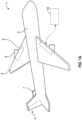
- FIG. 1A shows an aircraft 1 having a fuselage 2 with a wing 3 and tail assembly 4, which may have control surfaces 5.
- the wing 3 may include an engine 6, such as a gas turbine engine, and an auxiliary power unit 7 may be disposed at the tail assembly 4.
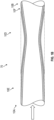
- FIG. 1B shows a component 10 of the aircraft 1.
- the component 10 may define a flow tube having an outer surface 10A with opposite axial ends 10B, 10C.
- the component 10 may define a neck region 10D between the ends 10B, 10C and upstream and downstream regions 10E, 10F that are adjacent to the neck region 10D.
- the neck region 10D may form a neck constriction, e.g., having a flow area that is smaller than flow areas through axially adjacent regions 10E, 10F of the component 10, to change flow characteristics therethrough, such as throttling the flow.
- the neck region 10D may not form a constriction, e.g., having a flow area that is the same as flow area through the axially adjacent regions 10E, 10F, if there is no need to change the characteristics therethrough.
- the component 10 is additively manufactured.
- the component 10 includes an element 70 defining a wall 50 having an outer boundary 80 and extending longitudinally from a first end 310 to a second end 320 and transversely from a first side 330 to a second side 340.
- the wall 50 is nonmetal and may be, e.g., a thermoplastic.
- the wall 50 defines a first segment 350 extending longitudinally between the first and second ends 310, 320 and transversely from the first side 330 to a segment junction 370.
- the wall 50 defines a second segment 360 extending longitudinally between the first and second ends 310, 330 and transversely from the second side 340 to the segment junction 370.
- the first segment 350 has a first coefficient of thermal expansion (CTE) and the second segment 360 has a second CTE that differs from the first CTE, to define a transverse CTE gradient.
- the second CTE may be lower than the first CTE.
- FIG. 2B shows one type of deformation that may be obtained, which is an arcuate shape. Strategic control of the CTE gradient may result in the controlled expansion and contraction of the neck of the flow control device 10.
- the element 70 shown in FIGS. 2A and 2B may have a first length L1 (or longitudinal span) before being subjected to thermal energy.
- the element 70 may have a second length L2 after being subject to thermal energy, where the second length L2 is less than the first length L1.
- the outer surface 71 of the element 70 may have an arc length L2x that is longer than L1.
- the first and second segments 350, 360 both may be formed of a first material having the first CTE.
- the first segment 350 may include first fibers 355 formed of a second material that differs from the first material and has the second CTE.
- the second segment 360 may also include second fibers 365 formed of a third material that differs from the first and second materials and has a third CTE that differs from the first and second CTEs.
- the third CTE may be greater than the second CTE. That is, one side of the illustrated element 70 deforms less than the other when subject to heat, resulting in the arcuate shape (or other predetermined shape) shown in FIG. 2B .
- the first segment 350 is formed of a first material having the first CTE.
- the second segment 360 is formed of a second material that differs from the first material and has the second CTE.
- the first segment 350 may define a first CTE gradient and the second segment may define a second CTE gradient.
- a maximum difference between the first CTE and the second CTE is at the first and second sides 330, 340 and a minimum difference between the first CTE and the second CTE is at the segment junction 370.
- the first CTE and the second CTE are the same as each other.
- applying thermal energy to the element 70 results in a predetermined curvature, similar to that shown in FIG 2B .
- the wall extends linearly between the first and second ends 310, 320.
- the element 70 shown in FIGS. 3A and 3B may have a first length L1 (or longitudinal span) before being subjected to thermal energy.
- the element 70 may have a second length L2 after being subject to thermal energy, where the second length L2 is less than the first length L1.
- the outer surface 71 of the element 70 may have an arc length L2x that is longer than L1.
- the element 70 may define one or more arc segments 72 between the first and second ends 310, 320 rather than being liner as shown in FIGS. 2A and 2B .
- the element 70 includes the first and second segments 350, 360 with the junction 370 therebetween that extends between the ends 310, 320.
- FIG. 5 shows the predetermined deformation of a lattice 73 of such elements 70, stacked one on top of the other, when subject to thermal energy.
- the element 70 shown in FIG. 4 may have a first length L1 (or longitudinal span) before being subjected to thermal energy.
- the element 70 as shown as the lattice 73 of FIG. 5 may have a second length L2 after being subject to thermal energy, where the second length L2 is less than the first length L1.
- thermoelectric junction 150 is disposed around the outer boundary 80, e.g., along the outer surface 71 of the second segment 360 and between opposite ends 310, 320 as a non-limiting example.
- the thermoelectric junction 150 otherwise may be between the first and second segments 350, 360, i.e. at the segment junction 370. This may enable selectively adding thermal energy to the element 70 ( FIG. 3B ) to obtain the predetermined deformation, such as the contraction or expansion of the neck of the flow control device 10.
- the thermoelectric junction 150 may form a Peltier or a Thomson device.
- alternating P and N-type pillars made with materials with different Seebeck coefficients, or legs are placed thermally in parallel to each other and electrically in series and joined with a thermally conducting plate on each side, e.g., ceramic, including a cooling plate 160 and a heating plate 170.
- a voltage is applied to the free ends of the two semiconductors, via connections 190 there is a flow of DC current across the junction of the semiconductors, causing a temperature difference.
- the side with the cooling plate 160 absorbs heat which is then transported by the semiconductor to the other side of the device.
- One of the cooling plate 160 or heating plate 170 may be exposed to the atmosphere if desired to bleed energy from it rather than directing energy from it back to the component 10.
- thermoelectric junction 150 is shown in FIG. 4 along the outer boundary 80, e.g., along the outer surface 71 of the second segment 360 and between opposite ends 310, 320 as a non-limiting example.
- the thermoelectric junction 150 otherwise may be between the first and second segments 350, 360, i.e., at the segment junction 370. This may enable selectively adding thermal energy to the lattice 73 ( FIG. 5 ) to obtain the predetermined deformation, such as the contraction or expansion of the neck of the flow control device 10.
- the flow control device 10 may define a base 75 having an outer boundary 80 extending longitudinally from a first end 310 to a second end 320 and transversely from a first side 330 to a second side 340.
- Beads 90 (each corresponding to an element 70 in the above embodiments) may be disposed within the outer boundary 80 and arranged as a lattice 73.
- Each of the beads 90 may be nonmetal, and may be, e.g., a thermoplastic.
- each of the beads 90 may have a bead void 100, e.g., in its center to form a closed loop.
- Each of the beads 90 may define first and second perimeter segments 110, 120 that are opposite each other and have a first CTE.
- Third and fourth perimeter segments 130, 140 may be opposite each other and adjacent to the first and second perimeter segments 110, 120.
- the third and fourth perimeter segments 130, 140 may have a second CTE that differs from the first CTE, to define a bead CTE gradient.
- each of the beads 90 may have an outer surface 52 and an inner surface 54.
- the inner surface 54 defines the bead void 100.
- the outer surface 52 of the first and second perimeter segments 110, 120 may have the first CTE.
- the inner surface 54 of the first and second perimeter segments 110, 120 may have the second CTE.
- the outer surface 52 of the third and fourth perimeter segments 130, 140 may have the second CTE.
- the inner surface 54 of the third and fourth perimeter segments 130, 140 may have the first CTE.
- each segment of the beads 90 may form a segment CTE gradient that is the opposite the adjacent CTE gradient and the same as the opposite bead segment.
- the bead 90 may deform to a predetermined shape when subject to thermal energy.
- the bead 90 may deform from an oval with a first radius R1 along its short axis to an oval with a second radius R2 along the short axis that is smaller than the first radius R1.
- the lattice 73 of beads 90 may have a first length L1 (or longitudinal span) before being subjected to thermal energy.
- the lattice 73 may have a second length L2 after being subjected to thermal energy, where the second length L2 is less than the first length L1.
- thermoelectric junction 150 may be disposed around the outer boundary 80, as illustrated around the second end 320 and portions of the first and second sides 330, 340, as non-limiting embodiments, or in one or more of the bead voids 100. This may enable selectively adding thermal energy to the lattice 73 to obtain the predetermined deformation, such as the expansion or contraction of the neck of the flow control device 10.
- the first and second ends 310, 320, along the outer boundary 80 of the base 75 may include a top elastomer layer 250 and a bottom elastomer layer 260. These layers may be utilized for enclosing the beads 90 that are otherwise exposes to the environment for the flow control device 10.
- the base 75 may include an elastomer segment 270 that extends from each of the beads 90 that are located along the outer boundary 80. As a result, adjacent ones of the elastomer segments 270 may overlap each other to define a flexible outer boundary cover.
- the base 75 may be formed as a block 76 having an outer surface 77 defining the outer boundary 80 having the geometry identified in FIG. 6 , including the first and second ends 310, 320 and the first and second sides 330, 340.
- the block 76 may define base voids 290. Each of the base voids 290 may be lined with one of the beads 90.
- the block 76 may be nonmetal, and may be, e.g., a thermoplastic.
- thermoelectric junction 150 may be disposed around the outer boundary 80 of the block 76, as illustrated around the second end 320 and portions of the first and second sides 330, 340, as non-limiting embodiments, or in one or more of the bead voids 100.
- a block 76 containing the beads 90 may have a first length L1 (or longitudinal span) before being subjected to thermal energy. As shown in FIG. 11B , the block 76 may have a second length L2 after being subjected to thermal energy, where the second length L2 is less than the first length L1.
- FIG. 12A shows an oval shaped bead 90, which may be formed as indicated above, in a normal state having a first width W1.
- FIG. 12B shows the oval bead 90 in a deformed state having a second width W2 that is less than the first width W1.
- the beads 90 do not need to be arcuate in shape.
- FIG. 13A shows a diamond shaped bead 90 in a normal state having a first width W1.
- FIG. 13B shows the diamond shaped bead 90 in a deformed state having a second width W2 that is less than the first width W1.
- FIG. 14A shows a random shaped bead 90 in a normal state having a first width W1.
- FIG. 14B shows the random shaped bead 90 in a deformed state having a second width W2 that is less than the first width W1.
- the desired deformation shape may determine the shape of the bead 90.
- FIGS. 15A and 15B show an equivalent structure 405 to the structures shown above and for example in FIGS. 2-4 .
- the first and second segment 350, 360 are at a temperature T1 in FIG. 15A , and T2 that is greater than T1 in FIG. 15B , i.e., they have received thermal input.
- the controlled thermal expansion shown in FIG. 15B results from the segments being integrally connected. That is, the first and second segments 350, 360 bend together in a predictable and controlled way. That is, the controlled thermal expansion of the first and second segments 350, 360 in the disclose embodiments provides for controlled manipulation of the component disclosed herein.
Landscapes
- Engineering & Computer Science (AREA)
- General Engineering & Computer Science (AREA)
- Mechanical Engineering (AREA)
- Chemical & Material Sciences (AREA)
- Materials Engineering (AREA)
- Physics & Mathematics (AREA)
- General Physics & Mathematics (AREA)
- Automation & Control Theory (AREA)
- Physical Or Chemical Processes And Apparatus (AREA)
Abstract
Description
- The embodiments are directed to a flow control device and more specifically to a flow control device formed of thermally adaptive material and a thermoelectric junction.
- Memory shape materials may be utilized for various applications to avoid the requirement of utilizing complex machinery. However, surrounding temperatures may undesirably control the shape of the material.
- Disclosed is a flow control device, including: a flow tube extending between upstream and downstream, and a neck region between the first and second ends, wherein the flow tube includes: a wall defining an outer boundary and extending longitudinally from a first end to a second end and transversely from a first side to a second side, wherein: the wall is nonmetal; the wall defines: a first segment extending longitudinally between the first and second ends and transversely from the first side to a segment junction; and a second segment extending longitudinally between the first and second ends and transversely from the second side to the segment junction; and the first segment has a first coefficient of thermal expansion (CTE) and the second segment has a second CTE that differs from the first CTE, to define a transverse CTE gradient.
- In addition to one or more aspects of the device or as an alternate, a thermoelectric junction is disposed around the outer boundary or between the first and second segments.
- In addition to one or more aspects of the device or as an alternate, the second CTE is lower than the first CTE.
- In addition to one or more aspects of the device or as an alternate, the first and second segments are formed of a first material having the first CTE; the first segment includes first fibers formed of a second material that differs from the first material and has the second CTE.
- In addition to one or more aspects of the device or as an alternate, the second segment includes second fibers formed of a third material that differs from the first and second materials and has a third CTE that differs from the first and second CTEs.
- In addition to one or more aspects of the device or as an alternate, the third CTE is greater than the second CTE.
- In addition to one or more aspects of the device or as an alternate, the first segment is formed of a first material having the first CTE; the second segment is formed of a second material that differs from the first material and has the second CTE.
- In addition to one or more aspects of the device or as an alternate, the first segment defines a first CTE gradient and the second segment defines a second CTE gradient such that a maximum difference between the first CTE and the second CTE is at the first and second sides and a minimum difference between the first CTE and the second CTE is at the segment junction.
- In addition to one or more aspects of the device or as an alternate, at the segment junction, the first CTE and the second CTE are the same as each other.
- In addition to one or more aspects of the device or as an alternate, the wall extends linearly between the first and second ends.
- In addition to one or more aspects of the device or as an alternate, the wall defines one or more arcs between the first and second ends.
- Disclosed is another flow control device, including: a flow tube extending between upstream and downstream, and a neck region between the first and second ends, wherein the flow tube includes: a base having an outer boundary extending longitudinally from a first end to a second end and transversely from a first side to a second side; and beads within the outer boundary, wherein each of the beads is nonmetal, has a bead void, and defines: first and second perimeter segments that are opposite each other and have a first CTE; and third and fourth perimeter segments that are opposite each other and adjacent to the first and second perimeter segments and have a second CTE that differs from the first CTE, to define a bead CTE gradient.
- In addition to one or more aspects of the another device or as an alternate, a thermoelectric junction is disposed around the outer boundary or in one or more of the bead voids.
- In addition to one or more aspects of the another device or as an alternate, each of the beads defines: an outer surface; and an inner surface, wherein the inner surface defines the bead void, wherein: the outer surface of the first and second perimeter segments has the first CTE, and the inner surface of the first and second perimeter segments has the second CTE; and the outer surface of the third and fourth perimeter segments has the second CTE, and the inner surface of the third and fourth perimeter segments has the first CTE.
- In addition to one or more aspects of the another device or as an alternate, the base includes a top elastomer layer that is disposed against the first end along the outer boundary and a bottom elastomer layer that is disposed against the second end along the outer boundary.
- In addition to one or more aspects of the another device or as an alternate, the base includes an elastomer segment that extends from each of the beads that are located along the outer boundary of the base, so that adjacent ones of the elastomer segments overlap each other to define a flexible outer boundary cover.
- In addition to one or more aspects of the another device or as an alternate, the base is formed as a block having an outer surface that defines the outer boundary and base voids, wherein each of the voids is lined with one of the beads.
- In addition to one or more aspects of the another device or as an alternate, the block is nonmetal.
- In addition to one or more aspects of the another device or as an alternate, each of the beads is oval shaped or diamond shaped.
- The following descriptions should not be considered limiting in any way. With reference to the accompanying drawings, like elements are numbered alike:
-
FIG. 1A shows an aircraft according to an embodiment; -
FIG. 1B shows a component according to an embodiment, where the component is a flow control device that may be utilized for the aircraft; -
FIG. 2A shows an element that may be utilized to form the component, where the element may have segments with fibers having different coefficients of thermal expansion (CTE) selected to provide a predetermined deformation; -
FIG. 2B shows the element ofFIG. 2A in a deformed state; -
FIG. 3A shows an alternative element with different materials having different coefficients of thermal expansion (CTE) selected to provide a predetermined deformation, and with a thermal junction; -
FIG. 3B shows the element ofFIG. 3A in a deformed state; -
FIG. 4 shows an alternative element formed with arcs between opposite ends; -
FIG. 5 shows a lattice having the element ofFIG. 4 , where the lattice is in a deformed state; -
FIG. 6 a base with beads that may be utilized for the component, and which includes a thermal junction within the beads or round an outer boundary of the base; -
FIG. 7A shows details of one of the beads; -
FIG. 7B shows the bead ofFIG. 7A in a deformed state; -
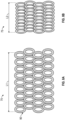
FIG. 8A shows the lattice ofFIG. 5 without the thermal junction, for simplicity; -
FIG. 8B shows the lattice ofFIG. 8A in a deformed state; -
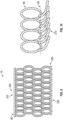
FIG. 9 shows the lattice ofFIG. 8A with top and bottom elastomer layers; -
FIG. 10 shows several of the beads at the bottom boundary of the lattice ofFIG. 8A , with elastic elements extending from each of the beads; -
FIG. 11A shows the element as a block with voids having the beads; -
FIG. 11B shows the block ofFIG. 11A in a deformed state; -
FIG. 12A shows an oval shaped bead, that can be utilized in disclosed embodiments utilizing beads, in a normal state; -
FIG. 12B shows the bead ofFIG. 12A in a deformed state; -
FIG. 13A shows a diamond shaped bead, that can be utilized in disclosed embodiments utilizing beads, in a normal state; -
FIG. 13B shows the bead ofFIG. 13A in a deformed state; -
FIG. 14A shows a random shaped bead, that can be utilized in disclosed embodiments utilizing beads, in a normal state; -
FIG. 14B shows the bead ofFIG. 14A in a deformed state; -
FIG. 14A shows an equivalent structure with a composition gradient formed of a plurality of materials having different coefficients of thermal expansion (CTE), at a temperature T1; and -
FIG. 15A shows an equivalent structure the structures shown above and for example inFIGS. 2-4 ; and -
FIG. 15B shows the structure ofFIG. 15A at a temperature T2>T1 and in a deformed state. - A detailed description of one or more embodiments of the disclosed apparatus and method are presented herein by way of exemplification and not limitation with reference to the Figures.
-
FIG. 1A shows anaircraft 1 having afuselage 2 with a wing 3 and tail assembly 4, which may havecontrol surfaces 5. The wing 3 may include anengine 6, such as a gas turbine engine, and an auxiliary power unit 7 may be disposed at the tail assembly 4. -
FIG. 1B shows acomponent 10 of theaircraft 1. Thecomponent 10 may define a flow tube having anouter surface 10A with opposite axial ends 10B, 10C. Thecomponent 10 may define aneck region 10D between theends 10B, 10C and upstream anddownstream regions neck region 10D. Theneck region 10D may form a neck constriction, e.g., having a flow area that is smaller than flow areas through axiallyadjacent regions component 10, to change flow characteristics therethrough, such as throttling the flow. Alternatively, theneck region 10D may not form a constriction, e.g., having a flow area that is the same as flow area through the axiallyadjacent regions component 10 is additively manufactured. - As shown in
FIG. 2 , thecomponent 10 includes anelement 70 defining awall 50 having anouter boundary 80 and extending longitudinally from afirst end 310 to asecond end 320 and transversely from afirst side 330 to asecond side 340. Thewall 50 is nonmetal and may be, e.g., a thermoplastic. - The
wall 50 defines afirst segment 350 extending longitudinally between the first and second ends 310, 320 and transversely from thefirst side 330 to asegment junction 370. Thewall 50 defines asecond segment 360 extending longitudinally between the first and second ends 310, 330 and transversely from thesecond side 340 to thesegment junction 370. - The
first segment 350 has a first coefficient of thermal expansion (CTE) and thesecond segment 360 has a second CTE that differs from the first CTE, to define a transverse CTE gradient. The second CTE may be lower than the first CTE. As a result, when subject to thermal energy, the controlled elastic deformation may be obtained.FIG. 2B shows one type of deformation that may be obtained, which is an arcuate shape. Strategic control of the CTE gradient may result in the controlled expansion and contraction of the neck of theflow control device 10. - The
element 70 shown inFIGS. 2A and 2B may have a first length L1 (or longitudinal span) before being subjected to thermal energy. Theelement 70 may have a second length L2 after being subject to thermal energy, where the second length L2 is less than the first length L1. However, theouter surface 71 of theelement 70 may have an arc length L2x that is longer than L1. - The first and
second segments first segment 350 may includefirst fibers 355 formed of a second material that differs from the first material and has the second CTE. In some embodiments, thesecond segment 360 may also includesecond fibers 365 formed of a third material that differs from the first and second materials and has a third CTE that differs from the first and second CTEs. The third CTE may be greater than the second CTE. That is, one side of the illustratedelement 70 deforms less than the other when subject to heat, resulting in the arcuate shape (or other predetermined shape) shown inFIG. 2B . - Turning to
FIG. 3A , in one embodiment, which has the same outer shape and segment geometry as the embodiment ofFIG. 2A , thefirst segment 350 is formed of a first material having the first CTE. Thesecond segment 360 is formed of a second material that differs from the first material and has the second CTE. Thefirst segment 350 may define a first CTE gradient and the second segment may define a second CTE gradient. A maximum difference between the first CTE and the second CTE is at the first andsecond sides segment junction 370. In one embodiment, at thesegment junction 370, the first CTE and the second CTE are the same as each other. As shown inFIG. 3B , with this configuration, applying thermal energy to theelement 70 results in a predetermined curvature, similar to that shown inFIG 2B . - In the embodiment of
FIG. 3A , the wall extends linearly between the first and second ends 310, 320. Theelement 70 shown inFIGS. 3A and 3B may have a first length L1 (or longitudinal span) before being subjected to thermal energy. Theelement 70 may have a second length L2 after being subject to thermal energy, where the second length L2 is less than the first length L1. However, theouter surface 71 of theelement 70 may have an arc length L2x that is longer than L1. - As shown in
FIG. 4 theelement 70 may define one ormore arc segments 72 between the first and second ends 310, 320 rather than being liner as shown inFIGS. 2A and 2B . Theelement 70 includes the first andsecond segments junction 370 therebetween that extends between theends FIG. 5 shows the predetermined deformation of alattice 73 ofsuch elements 70, stacked one on top of the other, when subject to thermal energy. - The
element 70 shown inFIG. 4 may have a first length L1 (or longitudinal span) before being subjected to thermal energy. Theelement 70 as shown as thelattice 73 ofFIG. 5 may have a second length L2 after being subject to thermal energy, where the second length L2 is less than the first length L1. - Turning back to
FIG. 3A , athermoelectric junction 150 is disposed around theouter boundary 80, e.g., along theouter surface 71 of thesecond segment 360 and between opposite ends 310, 320 as a non-limiting example. Thethermoelectric junction 150 otherwise may be between the first andsecond segments segment junction 370. This may enable selectively adding thermal energy to the element 70 (FIG. 3B ) to obtain the predetermined deformation, such as the contraction or expansion of the neck of theflow control device 10. - The
thermoelectric junction 150 may form a Peltier or a Thomson device. For example, alternating P and N-type pillars made with materials with different Seebeck coefficients, or legs, are placed thermally in parallel to each other and electrically in series and joined with a thermally conducting plate on each side, e.g., ceramic, including acooling plate 160 and aheating plate 170. When a voltage is applied to the free ends of the two semiconductors, viaconnections 190 there is a flow of DC current across the junction of the semiconductors, causing a temperature difference. The side with thecooling plate 160 absorbs heat which is then transported by the semiconductor to the other side of the device. One of thecooling plate 160 orheating plate 170 may be exposed to the atmosphere if desired to bleed energy from it rather than directing energy from it back to thecomponent 10. - Similarly, the
thermoelectric junction 150 is shown inFIG. 4 along theouter boundary 80, e.g., along theouter surface 71 of thesecond segment 360 and between opposite ends 310, 320 as a non-limiting example. Thethermoelectric junction 150 otherwise may be between the first andsecond segments segment junction 370. This may enable selectively adding thermal energy to the lattice 73 (FIG. 5 ) to obtain the predetermined deformation, such as the contraction or expansion of the neck of theflow control device 10. - Turning to
FIG. 6 , theflow control device 10 may define a base 75 having anouter boundary 80 extending longitudinally from afirst end 310 to asecond end 320 and transversely from afirst side 330 to asecond side 340. Beads 90 (each corresponding to anelement 70 in the above embodiments) may be disposed within theouter boundary 80 and arranged as alattice 73. Each of thebeads 90 may be nonmetal, and may be, e.g., a thermoplastic. - As shown in
FIG 7A , each of thebeads 90 may have abead void 100, e.g., in its center to form a closed loop. Each of thebeads 90 may define first andsecond perimeter segments fourth perimeter segments second perimeter segments fourth perimeter segments - In some embodiments, each of the
beads 90 may have anouter surface 52 and aninner surface 54. Theinner surface 54 defines thebead void 100. Theouter surface 52 of the first andsecond perimeter segments inner surface 54 of the first andsecond perimeter segments outer surface 52 of the third andfourth perimeter segments inner surface 54 of the third andfourth perimeter segments beads 90 may form a segment CTE gradient that is the opposite the adjacent CTE gradient and the same as the opposite bead segment. - As shown in
FIG. 7B , thebead 90 may deform to a predetermined shape when subject to thermal energy. For example, thebead 90 may deform from an oval with a first radius R1 along its short axis to an oval with a second radius R2 along the short axis that is smaller than the first radius R1. - As shown in
FIG. 8A , thelattice 73 ofbeads 90 may have a first length L1 (or longitudinal span) before being subjected to thermal energy. As shown inFIG. 8B , thelattice 73 may have a second length L2 after being subjected to thermal energy, where the second length L2 is less than the first length L1. - Turning back to
FIG. 6 , athermoelectric junction 150 may be disposed around theouter boundary 80, as illustrated around thesecond end 320 and portions of the first andsecond sides lattice 73 to obtain the predetermined deformation, such as the expansion or contraction of the neck of theflow control device 10. - Turning to
FIG. 9 , the first and second ends 310, 320, along theouter boundary 80 of the base 75 may include atop elastomer layer 250 and abottom elastomer layer 260. These layers may be utilized for enclosing thebeads 90 that are otherwise exposes to the environment for theflow control device 10. - Turning to
FIG. 10 , thebase 75 may include anelastomer segment 270 that extends from each of thebeads 90 that are located along theouter boundary 80. As a result, adjacent ones of theelastomer segments 270 may overlap each other to define a flexible outer boundary cover. - Turning to
FIG. 11A , thebase 75 may be formed as ablock 76 having an outer surface 77 defining theouter boundary 80 having the geometry identified inFIG. 6 , including the first and second ends 310, 320 and the first andsecond sides block 76 may define base voids 290. Each of the base voids 290 may be lined with one of thebeads 90. Theblock 76 may be nonmetal, and may be, e.g., a thermoplastic. - The
thermoelectric junction 150 may be disposed around theouter boundary 80 of theblock 76, as illustrated around thesecond end 320 and portions of the first andsecond sides - As shown in
FIG. 11A , ablock 76 containing thebeads 90 may have a first length L1 (or longitudinal span) before being subjected to thermal energy. As shown inFIG. 11B , theblock 76 may have a second length L2 after being subjected to thermal energy, where the second length L2 is less than the first length L1. -
FIG. 12A shows an oval shapedbead 90, which may be formed as indicated above, in a normal state having a first width W1.FIG. 12B shows theoval bead 90 in a deformed state having a second width W2 that is less than the first width W1. As indicated, thebeads 90 do not need to be arcuate in shape.FIG. 13A shows a diamond shapedbead 90 in a normal state having a first width W1.FIG. 13B shows the diamond shapedbead 90 in a deformed state having a second width W2 that is less than the first width W1.FIG. 14A shows a random shapedbead 90 in a normal state having a first width W1.FIG. 14B shows the random shapedbead 90 in a deformed state having a second width W2 that is less than the first width W1. The desired deformation shape may determine the shape of thebead 90. -
FIGS. 15A and 15B show anequivalent structure 405 to the structures shown above and for example inFIGS. 2-4 . Specifically, the first andsecond segment FIG. 15A , and T2 that is greater than T1 inFIG. 15B , i.e., they have received thermal input. The controlled thermal expansion shown inFIG. 15B results from the segments being integrally connected. That is, the first andsecond segments second segments - The terminology used herein is for the purpose of describing particular embodiments only and is not intended to be limiting of the present disclosure. As used herein, the singular forms "a", "an" and "the" are intended to include the plural forms as well, unless the context clearly indicates otherwise. It will be further understood that the terms "comprises" and/or "comprising," when used in this specification, specify the presence of stated features, integers, steps, operations, elements, and/or components, but do not preclude the presence or addition of one or more other features, integers, steps, operations, element components, and/or groups thereof.
- Those of skill in the art will appreciate that various example embodiments are shown and described herein, each having certain features in the particular embodiments, but the present disclosure is not thus limited. Rather, the present disclosure can be modified to incorporate any number of variations, alterations, substitutions, combinations, sub-combinations, or equivalent arrangements not heretofore described, but which are commensurate with the scope of the present disclosure. Additionally, while various embodiments of the present disclosure have been described, it is to be understood that aspects of the present disclosure may include only some of the described embodiments. Accordingly, the present disclosure is not to be seen as limited by the foregoing description, but is only limited by the scope of the appended claims.
Claims (15)
- A flow control device, comprising:
a flow tube extending between upstream and downstream, and a neck region (10D) between the first and second ends, wherein the flow tube comprises:a wall (50) defining an outer boundary (80) and extending longitudinally from a first end to a second end and transversely from a first side to a second side,wherein:the wall (50) is nonmetal;the wall (50) defines: a first segment (350) extending longitudinally between the first and second ends and transversely from the first side to a segment junction (370); and a second segment (360) extending longitudinally between the first and second ends and transversely from the second side to the segment junction (370); andthe first segment (350) has a first coefficient of thermal expansion (CTE) and the second segment (360) has a second CTE that differs from the first CTE, to define a transverse CTE gradient. - The flow control device of claim 1, wherein:
a thermoelectric junction is disposed around the outer boundary (80) or between the first and second segments. - The flow control device of claim 2, wherein the second CTE is lower than the first CTE.
- The flow control device of claim 3, wherein:the first and second segments are formed of a first material having the first CTE;the first segment (350) includes first fibers formed of a second material that differs from the first material and has the second CTE.
- The flow control device of claim 4, wherein:
the second segment (360) includes second fibers formed of a third material that differs from the first and second materials and has a third CTE that differs from the first and second CTEs, and optionally wherein the third CTE is greater than the second CTE. - The flow control device of any of claims 3-5, wherein:the first segment (350) is formed of a first material having the first CTE;the second segment (360) is formed of a second material that differs from the first material and has the second CTE, and optionally wherein:
the first segment (350) defines a first CTE gradient and the second segment (360) defines a second CTE gradient such that a maximum difference between the first CTE and the second CTE is at the first and second sides and a minimum difference between the first CTE and the second CTE is at the segment junction (370), and optionally wherein:
at the segment junction (370), the first CTE and the second CTE are the same as each other. - The flow control device of any of claims 3-6, wherein:
the wall (50) extends linearly between the first and second ends. - The flow control device of any of claims 3-7, wherein:
the wall (50) defines one or more arcs between the first and second ends. - A flow control device, comprising:
a flow tube extending between upstream and downstream, and a neck region (10D) between the first and second ends, wherein the flow tube comprises:a base having an outer boundary (80) extending longitudinally from a first end to a second end and transversely from a first side to a second side; andbeads within the outer boundary (80), wherein each of the beads is nonmetal, has a bead void, and defines:first and second perimeter segments that are opposite each other and have a first CTE; andthird and fourth perimeter segments that are opposite each other and adjacent to the first and second perimeter segments and have a second CTE that differs from the first CTE, to define a bead CTE gradient. - The flow control device of claim 9, wherein:
a thermoelectric junction is disposed around the outer boundary (80) or in one or more of the bead voids. - The flow control device of claim 10, wherein:
each of the beads defines:an outer surface; andan inner surface, wherein the inner surface defines the bead void,wherein:the outer surface of the first and second perimeter segments has the first CTE, and the inner surface of the first and second perimeter segments has the second CTE; andthe outer surface of the third and fourth perimeter segments has the second CTE, and the inner surface of the third and fourth perimeter segments has the first CTE. - The flow control device of claim 10 or 11, wherein:
the base includes a top elastomer layer that is disposed against the first end along the outer boundary (80) and a bottom elastomer layer that is disposed against the second end along the outer boundary (80). - The flow control device of any of claims 10-12, wherein:
the base includes an elastomer segment that extends from each of the beads that are located along the outer boundary (80) of the base, so that adjacent ones of the elastomer segments overlap each other to define a flexible outer boundary cover. - The flow control device of any of claims 10-13, wherein:
the base is formed as a block having an outer surface that defines the outer boundary (80) and base voids, wherein each of the voids is lined with one of the beads, and optionally wherein the block is nonmetal. - The flow control device of any of claims 10-14, wherein each of the beads is oval shaped or diamond shaped.
Applications Claiming Priority (1)
| Application Number | Priority Date | Filing Date | Title |
|---|---|---|---|
| US18/464,164 US20250085725A1 (en) | 2023-09-08 | 2023-09-08 | Flow control device formed of thermally adaptive material and a thermoelectric junction |
Publications (2)
| Publication Number | Publication Date |
|---|---|
| EP4530436A2 true EP4530436A2 (en) | 2025-04-02 |
| EP4530436A3 EP4530436A3 (en) | 2025-05-28 |
Family
ID=92538857
Family Applications (1)
| Application Number | Title | Priority Date | Filing Date |
|---|---|---|---|
| EP24196240.6A Pending EP4530436A3 (en) | 2023-09-08 | 2024-08-23 | Flow control device formed of thermally adaptive material and a thermoelectric junction |
Country Status (2)
| Country | Link |
|---|---|
| US (1) | US20250085725A1 (en) |
| EP (1) | EP4530436A3 (en) |
Families Citing this family (1)
| Publication number | Priority date | Publication date | Assignee | Title |
|---|---|---|---|---|
| US12384515B2 (en) | 2023-09-08 | 2025-08-12 | Hamilton Sundstrand Corporation | Airfoil formed of thermally adaptive materials and a thermoelectric junction |
Family Cites Families (18)
| Publication number | Priority date | Publication date | Assignee | Title |
|---|---|---|---|---|
| US3513881A (en) * | 1967-07-24 | 1970-05-26 | Garrett Corp | Flow regulator having thrust recovery |
| US3687365A (en) * | 1970-09-10 | 1972-08-29 | Gen Electric | Thermostatic flow controller |
| US4418549A (en) * | 1980-12-12 | 1983-12-06 | Courneya Calice G | Apparatus for extracting potable water |
| US4441653A (en) * | 1981-06-11 | 1984-04-10 | Paragon Resources, Inc. | Bi-metallic vane vent damper |
| US4454983A (en) * | 1982-02-04 | 1984-06-19 | Tarvis Jr Robert J | Temperature controlled valve |
| US5481184A (en) * | 1991-12-31 | 1996-01-02 | Sarcos Group | Movement actuator/sensor systems |
| US5720339A (en) * | 1995-03-27 | 1998-02-24 | Glass; David E. | Refractory-composite/heat-pipe-cooled leading edge and method for fabrication |
| US6371437B1 (en) * | 1999-01-30 | 2002-04-16 | Ogontz Corporation | Thermally operated valve for automatically modulating the flow of fluids and methods and tool for making the same |
| US6409147B1 (en) * | 2000-06-13 | 2002-06-25 | Thomas M. Kenny | Thermally operated valve for automatically modulating the flow of fluids |
| US7243409B2 (en) * | 2003-07-09 | 2007-07-17 | Lewis John K | Weldable conduit method of forming |
| TW200728605A (en) * | 2006-01-20 | 2007-08-01 | Univ Tamkang | Thermo-buckled micro-actuator unit made of polymer with high thermal expansion coefficient |
| AU2007240171A1 (en) * | 2006-12-11 | 2008-06-26 | Fisher & Paykel Appliances Limited | Variable flow valve |
| US8205668B2 (en) * | 2008-06-24 | 2012-06-26 | GM Global Technology Operations LLC | Heat exchanger with disimilar metal properties |
| IL221669A0 (en) * | 2011-08-28 | 2012-12-31 | Heliofocus Ltd | Fluid transfer assembly |
| DE102012205262B4 (en) * | 2012-03-30 | 2024-09-26 | Ford Global Technologies, Llc | Variable flow resistance |
| CA3097190A1 (en) * | 2017-06-14 | 2018-12-20 | The Royal Institution For The Advancement Of Learning/Mcgill University | Lattice metamaterial having programed thermal expansion |
| JP7314272B2 (en) * | 2018-12-11 | 2023-07-25 | ゼネラル・エレクトリック・カンパニイ | Distributed nested cell damping system |
| TWI714279B (en) * | 2019-09-24 | 2020-12-21 | 丁原傑 | Temperature compensation current limiting device and elastic infusion system |
-
2023
- 2023-09-08 US US18/464,164 patent/US20250085725A1/en active Pending
-
2024
- 2024-08-23 EP EP24196240.6A patent/EP4530436A3/en active Pending
Also Published As
| Publication number | Publication date |
|---|---|
| US20250085725A1 (en) | 2025-03-13 |
| EP4530436A3 (en) | 2025-05-28 |
Similar Documents
| Publication | Publication Date | Title |
|---|---|---|
| EP4520964A1 (en) | Actuator formed of thermally adaptive material and a thermoelectric junction | |
| US20250085725A1 (en) | Flow control device formed of thermally adaptive material and a thermoelectric junction | |
| EP1661189B1 (en) | Thermoelectric power generator for a gas turbine engine | |
| US10365049B2 (en) | Passive thermal diode | |
| US9025333B1 (en) | Tunable thermal switch | |
| CN110822205A (en) | Device for heat exchange with an elastic heating element surrounding a fluid line | |
| EP2868896A1 (en) | Turbo engine with an energy harvesting device, energy harvesting device and a method for energy harvesting | |
| US11011692B2 (en) | Thermoelectric device utilizing non-zero berry curvature | |
| US8829324B2 (en) | Anisotropic ambipolar transverse thermoelectrics and methods for manufacturing the same | |
| EP4520981A1 (en) | Aircraft flow control device formed of thermally adaptive materials and a thermoelectric junction | |
| Ziabari et al. | Minimizing thermally induced interfacial shearing stress in a thermoelectric module with low fractional area coverage | |
| Karimi et al. | Performance analysis of multi-stage thermoelectric coolers | |
| EP4520965A1 (en) | Aircraft actuator formed of thermally adaptive materials and a thermoelectric junction | |
| US12213379B2 (en) | Thermoelectrically actuated phase change thermal energy storage (TES) module | |
| US9506675B1 (en) | Thermoelectric coolers with asymmetric conductance | |
| US20250084766A1 (en) | Aircraft airfoil formed from thermally adaptive materials and including damping element, stiffening element, and a thermoelectric junction | |
| EP4520967A1 (en) | Compressor shroud with controllable bypass component formed of thermally adaptive materials and a thermoelectric junction | |
| US20190308753A1 (en) | Variable heat rejection device | |
| EP4520656A1 (en) | Airfoil formed of thermally adaptive materials and a thermoelectric junction | |
| Huang et al. | Thermal and thermal stress analysis of a thin-film thermoelectric cooler under the influence of the Thomson effect | |
| EP4528101A1 (en) | Aircraft component additively having thermally adaptive material and a thermoelectric junction | |
| JP2018069726A (en) | Method and apparatus for maintaining material temperature difference using thermoelectric device during high temperature bonding repair | |
| JP4622577B2 (en) | Cascade module for thermoelectric conversion | |
| KR101735969B1 (en) | Thread comprising a thermoelectric material and method for producing a component for a thermoelectric module | |
| EP4520966A1 (en) | Locking device formed of thermally adaptive multi-metallic material and a thermoelectric junction and method of manufacturing the same |
Legal Events
| Date | Code | Title | Description |
|---|---|---|---|
| PUAI | Public reference made under article 153(3) epc to a published international application that has entered the european phase |
Free format text: ORIGINAL CODE: 0009012 |
|
| STAA | Information on the status of an ep patent application or granted ep patent |
Free format text: STATUS: THE APPLICATION HAS BEEN PUBLISHED |
|
| AK | Designated contracting states |
Kind code of ref document: A2 Designated state(s): AL AT BE BG CH CY CZ DE DK EE ES FI FR GB GR HR HU IE IS IT LI LT LU LV MC ME MK MT NL NO PL PT RO RS SE SI SK SM TR |
|
| PUAL | Search report despatched |
Free format text: ORIGINAL CODE: 0009013 |
|
| AK | Designated contracting states |
Kind code of ref document: A3 Designated state(s): AL AT BE BG CH CY CZ DE DK EE ES FI FR GB GR HR HU IE IS IT LI LT LU LV MC ME MK MT NL NO PL PT RO RS SE SI SK SM TR |
|
| RIC1 | Information provided on ipc code assigned before grant |
Ipc: F02C 7/057 20060101ALI20250422BHEP Ipc: F02C 7/042 20060101ALI20250422BHEP Ipc: F01D 17/14 20060101ALI20250422BHEP Ipc: F16K 7/02 20060101ALI20250422BHEP Ipc: F16K 7/04 20060101ALI20250422BHEP Ipc: F01D 5/14 20060101AFI20250422BHEP |
|
| STAA | Information on the status of an ep patent application or granted ep patent |
Free format text: STATUS: REQUEST FOR EXAMINATION WAS MADE |
|
| 17P | Request for examination filed |
Effective date: 20251124 |