EP4530388A1 - Drum structure for a tumble dryer and tumble dryer - Google Patents
Drum structure for a tumble dryer and tumble dryer Download PDFInfo
- Publication number
- EP4530388A1 EP4530388A1 EP24201822.4A EP24201822A EP4530388A1 EP 4530388 A1 EP4530388 A1 EP 4530388A1 EP 24201822 A EP24201822 A EP 24201822A EP 4530388 A1 EP4530388 A1 EP 4530388A1
- Authority
- EP
- European Patent Office
- Prior art keywords
- side wall
- quadrant
- drum structure
- wall
- perforation
- Prior art date
- Legal status (The legal status is an assumption and is not a legal conclusion. Google has not performed a legal analysis and makes no representation as to the accuracy of the status listed.)
- Pending
Links
Images


Classifications
-
- D—TEXTILES; PAPER
- D06—TREATMENT OF TEXTILES OR THE LIKE; LAUNDERING; FLEXIBLE MATERIALS NOT OTHERWISE PROVIDED FOR
- D06F—LAUNDERING, DRYING, IRONING, PRESSING OR FOLDING TEXTILE ARTICLES
- D06F58/00—Domestic laundry dryers
- D06F58/02—Domestic laundry dryers having dryer drums rotating about a horizontal axis
- D06F58/04—Details
-
- D—TEXTILES; PAPER
- D06—TREATMENT OF TEXTILES OR THE LIKE; LAUNDERING; FLEXIBLE MATERIALS NOT OTHERWISE PROVIDED FOR
- D06F—LAUNDERING, DRYING, IRONING, PRESSING OR FOLDING TEXTILE ARTICLES
- D06F58/00—Domestic laundry dryers
- D06F58/02—Domestic laundry dryers having dryer drums rotating about a horizontal axis
- D06F58/04—Details
- D06F58/06—Mountings for the rotating drums
-
- D—TEXTILES; PAPER
- D06—TREATMENT OF TEXTILES OR THE LIKE; LAUNDERING; FLEXIBLE MATERIALS NOT OTHERWISE PROVIDED FOR
- D06F—LAUNDERING, DRYING, IRONING, PRESSING OR FOLDING TEXTILE ARTICLES
- D06F58/00—Domestic laundry dryers
- D06F58/02—Domestic laundry dryers having dryer drums rotating about a horizontal axis
- D06F58/04—Details
- D06F58/08—Driving arrangements
Definitions
- the present invention relates to a drum structure for a tumble dryer and to a tumble dryer, particularly for domestic use, which provides to dry laundry housed in a laundry drum, by rotating the laundry drum and generating a drying air flow through the laundry drum.
- the hot, dry drying air is conveyed into the laundry drum, where, passing through the wet laundry, it causes the evaporation of the water contained in the fabrics.
- the moisture-laden drying air passes through a heat exchanger where it is cooled in order to extract the moisture from it through condensation.
- the dehumidified drying air is then suctioned again by the fan, heated and directed into the laundry drum.
- Tumble dryers are known in which the laundry drum comprises a rear wall (sometimes called rear flange) perforated to allow the entry of drying air, a circumferential side wall (typically non-perforated) and a front edge or an annular front wall which delimits a front opening of the laundry drum for the insertion and extraction of the laundry into and from the laundry drum, and for the exiting of the drying air flow from the laundry drum after passing through and lapping the laundry, absorbing the moisture therefrom.
- the rear, side and front walls of the drum together form a substantially rigid hollow body, with a rotating body geometry.
- the pivoting support can be cantilevered by means of a drive hub rigidly connected to the rear wall of the laundry drum and by resting the laundry drum on a plurality of support rollers on a front side of the laundry drum.
- an electric motor with a transmission, for example a belt transmission between the electric motor and the drive hub or between the motor and the side wall of the laundry drum or, alternatively, an electric motor whose rotor is directly coupled to the rear wall of the laundry drum to transmit the rotary motion thereto.
- a transmission for example a belt transmission between the electric motor and the drive hub or between the motor and the side wall of the laundry drum or, alternatively, an electric motor whose rotor is directly coupled to the rear wall of the laundry drum to transmit the rotary motion thereto.
- the laundry drum prefferably be made of stainless steel sheet and it has also been proposed for at least part of the laundry drum to be made of plastic material.
- the ventilation duct that guides the drying air flow to the perforated rear wall extends from a radially external side of the laundry drum along a rear side of the laundry drum, and parallel to the rear wall, and opens in an axial direction towards the inside of the laundry drum.
- the resulting air path thus has a direction orthogonal to the rotation axis of the laundry drum before being diverted by 90° through the perforation of the rear wall of the laundry drum inside it. This results in a non-uniform flow rate of the drying air flow as it enters the laundry drum.
- the air accumulation pressure (and thus the inlet air flow rate) is greater than in the regions further upstream.
- the rotation of the laundry drum and its rear wall generates a radial fan effect on the air flow, diverting part of it radially towards the outside, while ideally the laundry to be dried should spin inside the laundry drum and be lapped and crossed by an air flow that is as axial and uniform as possible.
- Laundry drums made of sheet steel, both galvanized or stainless, manufactured by pressing operations, mechanical expansion and joining of components by bending the edges, are undesirably heavy, require expensive raw materials of uncertain supply, and complex and expensive manufacturing processes.
- Plastic laundry drums made by injection molding and subsequent joining of components through gluing and ultrasonic welding, are made of a less expensive and lighter material.
- the aim of the present invention is thus to provide a laundry drum structure for a tumble dryer and a tumble dryer, having characteristics such to overcome at least some of the drawbacks of the prior art.
- a laundry drum structure for a tumble dryer of the type comprising a laundry compartment for containing the laundry to be dried and a drying circuit which conveys a drying air flow through the laundry compartment, in which the drum structure comprises:
- the plastic side wall can be manufactured using a single injection or blow molding process, without additional joining, gluing or welding of components, significantly simplifying manufacturing and reducing the cost of the drum structure.
- the perforation for the entry of the drying air into the laundry compartment remains stationary, eliminating the radial fan effect, reducing noise, and allowing configuration and distribution of the perforation openings aimed at directing the air flow and distributing the flow rate as desired.
- the invention obviates the need to provide a cantilever support for the laundry drum (meaning the set of rear and lateral walls) via a support shaft or hub and the relative fastenings and reinforcements to the rear wall.
- a cantilever support for the laundry drum meaning the set of rear and lateral walls
- the absence of these components also allows perforation openings to be provided also in the central region (otherwise occupied) of the rear wall.
- a tumble dryer 1 comprises a housing 2 which accommodates a laundry compartment 3 delimited by a drum structure 4, for containing the laundry to be dried, a motor 5 for moving the laundry in the laundry compartment 3, and a drying circuit 6 which conveys a drying air flow 15 through the laundry compartment 3.
- the drum structure 4 comprises:
- the plastic side wall 7 can be manufactured using a single injection or blow molding process, without additional joining, gluing or welding of components, significantly simplifying manufacturing and reducing the cost of the drum structure 4.
- the perforation 22 for the entry of the drying air 15 into the laundry compartment 3 remains stationary, eliminating the radial fan effect and reducing noise and allowing a configuration and distribution of the perforation openings 22 aimed at directing the air flow 15 and distributing the flow rate as desired.
- the invention obviates the need to provide a cantilever support for the laundry drum (meaning the set of rear 13 and lateral 7 walls) via a support shaft or hub and the relative fastenings and reinforcements to the rear wall.
- the absence of these components also allows perforation openings 22 to be provided even in the central region (otherwise occupied) of the rear wall 13.
- the rear wall 13 is made of plastic material, advantageously fiber-reinforced plastic material, and preferably formed by injection molding. This further reduces the material and manufacturing costs of the drum structure 4, allowing, for example, the rear wall to be made by a single injection molding process during which the perforation openings 22 are also made without wasting material and without any shearing or punching processes, as well as the annular receiving seat 14.
- the rear wall 13 comprises a circular bottom portion 23, e.g., concave towards the inside of the laundry compartment 3 or substantially flat, delimited by the annular receiving seat 14 and in which bottom portion the entire perforation 22 is formed.
- the bottom portion 23 is imaginarily divided by a first horizontal diameter 24 and a second vertical diameter 25, perpendicular to each other and radial with respect to the rotation axis 8, into:
- a total "upper" opening area of the perforation 22 in the first quadrant 26_1 and second quadrant 26_2 put together is smaller than a total "lower” opening area of the perforation 22 in the third quadrant 26_3 and fourth quadrant 26_4 put together, in particular when the drying air 15 in the drying circuit 6 is conveyed from below underneath the side wall 7 upwards to the rear wall 13.
- a total "upper" opening area of the perforation 22 in the first quadrant 26_1 and second quadrant 26_2 put together is greater than a total "lower” opening area of the perforation 22 in the third quadrant 26_3 and fourth quadrant 26_4 put together, in particular when the drying air 15 in the drying circuit 6 is conveyed from above over the side wall 7 downwards to the rear wall 13.
- a total "left" opening area of the perforation 22 in the first quadrant 26_1 and third quadrant 26_3 put together is smaller than a total "right” opening area of the perforation 22 in the second quadrant 26_2 and fourth quadrant 26_4 put together, in particular when the drying air 15 in the drying circuit 6 is conveyed from the right side of the side wall 7 to the left (again seen from inside the laundry compartment 3) to the rear wall 13.
- a total "left" opening area of the perforation 22 in the first quadrant 26_1 and third quadrant 26_3 put together is greater than a total "right” opening area of the perforation 22 in the second quadrant 26_2 and fourth quadrant 26_4 put together, in particular when the drying air 15 in the drying circuit 6 is conveyed from the left side of the side wall 7 to the right (seen from inside the laundry compartment 3) to the rear wall 13.
- the annular receiving seat 14 comprises an annular groove 27 facing the annular rear edge 9 and forming and accommodating a front gasket 28 in sliding contact (with low friction) with the rear annular edge 9.
- the front gasket 28 has the function of sealing the rotating coupling of the air circuit, consisting of the side wall 7 and stationary wall 13, and may comprise an elastically yielding base (for generating an elastic contact preload and compensating for geometric tolerances), fastened to the stationary wall 13, and which supports a sealing gasket, in frontal contact with the side wall 7 and made of a low-friction material, for example wool-based felt or synthetic fibers.
- the annular groove 27 is delimited by two walls 29 which flank the rear annular edge 9 and stabilize its circular shape in case of unwanted deformations due to uneven and unbalanced loads of laundry.
- the rear support portion 17 is directly formed by the rear wall 13 and, thus the rear support rollers 16 are directly supported by the rear wall 13.
- the rear support rollers 16 comprise two rollers arranged in the same rear support plane 30 orthogonal to the rotation axis 8 in a symmetrical lower-side position with respect to a vertical plane radial to the rotation axis 8.
- the drum structure 4 comprises a rear cover 31 made of a plastic material, e.g. fiber-reinforced plastic material, connected to the rear wall 13 on a rear side of the drum structure 4, opposite to the side wall 7, and together with the rear wall 13 defining a rear air channel 32 of the drying circuit 6 in communication with the perforation 22 of the rear wall 13.
- a plastic material e.g. fiber-reinforced plastic material
- rear air channel 32 is made of plastic material further reduces the weight and costs for the material and for manufacturing the drum structure 4, reduces risks of corrosion and facilitates the assembly of the components exclusively made of synthetic material.
- the rear cover 32 may be mounted on the rear wall by:
- the rear cover 32 is formed in one piece with the rear wall, by injection molding.
- the rear cover 32 has:
- the side wall 7 forms one or more dragging paddles 35 protruding towards the inside of the laundry compartment 3 and formed in one piece with the side wall 7, e.g., by injection molding or blow molding. This reduces the number of individual components to be assembled and the manufacturing costs.
- the one or more dragging paddles 35 are formed by local recesses of the side wall 7 which form concave cavities on the radially outer surface of the side wall 7 and corresponding convex protrusions on the radially inner surface of the side wall 7.
- the one or more dragging paddles 35 do not extend up to the rear edge 9 and do not extend up to the front edge 11, so as not to negatively interfere with the closing function of the laundry compartment 3 on the rear and/or front sides of the side wall 7.
- the one or more dragging paddles 35 extend into a central region of the axial extension of the side wall 7, between the front support track 21 and the rear support track 20, without however reaching the front 21 and rear 20 support tracks, so as not to negatively interfere with the rolling of the front 18 and rear 16 support rollers.
- the dragging paddles 35 (and/or the entire inner surface of the side wall 7 in the extension region of the dragging paddles 35) have a shape that tapers (or has converging draft angles), going radially towards the rotation axis 8. This allows the side wall 7 to be manufactured particularly quickly and cheaply, by injection molding with the aid of an internal mold radially retractable towards the inside.
- the dragging paddles (and/or the entire inner surface of the side wall 7 in the extension region of the dragging paddles 35) have a shape that widens (or has diverging draft angles), going radially outwards. This allows the side wall 7 to be manufactured particularly quickly and cheaply, by injection molding with the aid of an external mold that can be radially opened/retracted towards the outside.
- the side wall 7 forms exactly two dragging paddles 37 in diametrically opposite positions with respect to a central radial plane 36 (preferably of symmetry) of the side wall 7. This makes it possible to use only two opposing external mold “cheeks” that are closable and openable in a direction orthogonal to the central radial plane 36.
- the side wall 7 forms a cylindrical pulley seat 37, facing radially outwards and delimited bilaterally by two annular parallel ribs 38 for securely accommodating a belt 39 for the transmission of a rotary motion from the electric motor 5 to the side wall 7.
- the pulley seat 37 and the two annular parallel ribs 38 are also made of plastic material and formed in one piece with the side wall 7. This reduces the number of individual components to be assembled and the manufacturing costs.
- the side wall 7 can form a ring gear (not shown in the figures) adapted to be engaged by a gear for the transmission of a rotary motion from the electric motor 5 to the side wall 7.
- the ring gear is also made of plastic material and formed in one piece with the side wall 7.
- the rear support track 20 and the front support track 21 have a circular cylindrical shape
- the side wall 7 has a non-cylindrical shape, e.g. a shape with one or more frustoconical segments and/or one or more steps formed between neighboring frustoconical and/or cylindrical segments.
- the drum structure 4 or the tumble dryer 1 comprises a stationary front wall 40, transverse or orthogonal to the rotation axis 8 and forming an annular front receiving seat 41 which engages the front edge 11 of the side wall 7 pivotally about the rotation axis 8 without obstructing the front opening 12 of the pivoting side wall 7.
- the front receiving seat 41 comprises an annular groove 42 facing the annular rear edge 11 and forming or accommodating a (further) front gasket 28 in sliding contact (with low friction) with the front annular edge 11.
- the annular groove 42 is delimited by two walls 43 which flank the rear annular edge 11 and stabilize its circular shape in case of unwanted deformations due to uneven and unbalanced loads of laundry.
- the front support portion 19 is directly formed by the stationary front wall 40 and, thus the front support rollers 18 are directly supported by the front wall 40.
- the front support rollers 18 comprise two rollers arranged in the same front support plane 44 orthogonal to the rotation axis 8 in a symmetrical lower-side position with respect to a vertical plane radial to the rotation axis 8.
- the front opening 12 is openable and closable by a front door 45 of the tumble dryer 1.
- the drying air 15 is conveyed by means of a fan 46 (actuated by a motor 47), heated by means of an electric resistor 48 and directed into the laundry compartment 3, where, as it passes through the wet laundry, it causes the water contained in the fabrics to evaporate.
- the drying air 15 laden with moisture passes through a heat exchanger 49, where it is cooled, for example, by means of a flow of cold water or fresh air 50 conveyed by means of a second fan (operated preferably but not necessarily by means of the same electric motor 47), so as to remove the moisture therefrom by means of condensation.
- the condensate is collected in a removable condensation container or discharged by a discharge pump and/or together with the cooling water.
- the dehumidified drying air 15 is then suctioned again by the fan 46, heated by means of the electrical resistor 48 and re-directed into the laundry compartment 3. Upstream of the heat exchanger 49 (in which the moisture is removed) a lint filter 51 is arranged.
- the drying air 15 laden with moisture passes through a first (cold) heat exchanger 52 formed by an evaporator 52' of the heat pump, where the air 15 is cooled so as to remove the moisture therefrom by condensation.
- the condensate may be collected in a removable condensation container or discharged, e.g. by a discharge pump.
- the dehumidified and cooled drying air 15 is then directed into a second (hot) heat exchanger formed by a heat pump condenser 53, where the air is heated.
- the dehumidified and heated air is suctioned by means of a fan 46 and directed again into the laundry compartment 3 so as to continue extracting moisture from the laundry.
- the heat pump further comprises a compressor 54 which suctions a coolant fluid through the evaporator 52', where the fluid itself evaporates at low pressure (absorbing the heat of the drying air 15), compresses the coolant fluid and pushes it into the condenser 53 where the compressed and heated coolant fluid condenses and cools at high pressure (releasing its heat to the drying air 15).
- the coolant fluid passes through an expansion valve 55 which reduces the pressure of the fluid with consequent lowering of the temperature and, then, returns again into the evaporator 52', restarting the cycle.
- a lint filter 51 is arranged upstream of the first heat exchanger 52 (evaporator 52').
- the tumble dryer 1 comprises an electronic control system 56 in signal connection with and controlling the electric power supply of the individual functional groups of the tumble dryer 1 ( Figures 8 and 9 ).
Landscapes
- Engineering & Computer Science (AREA)
- Textile Engineering (AREA)
- Detail Structures Of Washing Machines And Dryers (AREA)
Abstract
A drum structure (4) for a tumble dryer (1) comprises a pivoting side wall (7) made of a plastic material, tubular in shape, having an annular rear edge (9) delimiting a rear opening (10), as well as an annular front edge (11) delimiting a front opening (12), a stationary rear wall (13) forming an annular receiving seat (14) which engages the rear edge (9) of the side wall (7) pivotally about a rotation axis (8) and so that the stationary rear wall (13) closes the rear opening (10) of the pivoting side wall (7), and a perforation (22) to allow the drying air flow (15) to pass through the stationary rear wall (13) in a laundry compartment (3) delimited by the pivoting side wall (7) and the stationary rear wall (13), a plurality of rear support rollers (16) and a plurality of front support rollers (18) which support the side wall (7) pivotally about the rotation axis (8) with respect to the stationary rear wall (13).
Description
- The present invention relates to a drum structure for a tumble dryer and to a tumble dryer, particularly for domestic use, which provides to dry laundry housed in a laundry drum, by rotating the laundry drum and generating a drying air flow through the laundry drum.
- In a closed drying circuit with an electrical resistor or heat pump, the hot, dry drying air is conveyed into the laundry drum, where, passing through the wet laundry, it causes the evaporation of the water contained in the fabrics. After leaving the laundry drum, the moisture-laden drying air passes through a heat exchanger where it is cooled in order to extract the moisture from it through condensation. The dehumidified drying air is then suctioned again by the fan, heated and directed into the laundry drum.
- Tumble dryers are known in which the laundry drum comprises a rear wall (sometimes called rear flange) perforated to allow the entry of drying air, a circumferential side wall (typically non-perforated) and a front edge or an annular front wall which delimits a front opening of the laundry drum for the insertion and extraction of the laundry into and from the laundry drum, and for the exiting of the drying air flow from the laundry drum after passing through and lapping the laundry, absorbing the moisture therefrom. The rear, side and front walls of the drum together form a substantially rigid hollow body, with a rotating body geometry.
- It is also known to support the laundry drum pivotally about a rotation axis, which is typically a central axis of the geometry of the laundry drum. The pivoting support can be cantilevered by means of a drive hub rigidly connected to the rear wall of the laundry drum and by resting the laundry drum on a plurality of support rollers on a front side of the laundry drum.
- To rotate the drum about the rotation axis, it is known to provide an electric motor with a transmission, for example a belt transmission between the electric motor and the drive hub or between the motor and the side wall of the laundry drum or, alternatively, an electric motor whose rotor is directly coupled to the rear wall of the laundry drum to transmit the rotary motion thereto.
- It is known for the laundry drum to be made of stainless steel sheet and it has also been proposed for at least part of the laundry drum to be made of plastic material.
- As an alternative to the traditional concept of a rigid pivoting drum, it has also been proposed to create a laundry compartment using a flexible band-shaped side wall, guided and moved along a closed, non-circular path, so as to delimit a space for containing the laundry and moving the laundry itself. In this case, the rear and front walls delimiting the laundry compartment do not move in unison together with the band-shaped side wall.
- Due to the arrangement of the drying circuit components, typically radially externally and centrally or laterally below the laundry drum, the ventilation duct that guides the drying air flow to the perforated rear wall extends from a radially external side of the laundry drum along a rear side of the laundry drum, and parallel to the rear wall, and opens in an axial direction towards the inside of the laundry drum.
- The resulting air path thus has a direction orthogonal to the rotation axis of the laundry drum before being diverted by 90° through the perforation of the rear wall of the laundry drum inside it. This results in a non-uniform flow rate of the drying air flow as it enters the laundry drum. In particular, in a region at the bottom of the ventilation duct, the air accumulation pressure (and thus the inlet air flow rate) is greater than in the regions further upstream.
- Moreover, the rotation of the laundry drum and its rear wall generates a radial fan effect on the air flow, diverting part of it radially towards the outside, while ideally the laundry to be dried should spin inside the laundry drum and be lapped and crossed by an air flow that is as axial and uniform as possible.
- Further, the rotating rear wall, crossed by the air flow, is a source of unwanted noise.
- Laundry drums made of sheet steel, both galvanized or stainless, manufactured by pressing operations, mechanical expansion and joining of components by bending the edges, are undesirably heavy, require expensive raw materials of uncertain supply, and complex and expensive manufacturing processes.
- Plastic laundry drums, made by injection molding and subsequent joining of components through gluing and ultrasonic welding, are made of a less expensive and lighter material. However, the joining of multiple components (side wall and perforated rear wall) made separately through injection molding, implies undesirable manufacturing costs and complexity.
- The aim of the present invention is thus to provide a laundry drum structure for a tumble dryer and a tumble dryer, having characteristics such to overcome at least some of the drawbacks of the prior art.
- Particular aims of the invention are to:
- increase the construction simplicity of the laundry drum structure, and reduce the number of individual components to be joined together by welding, gluing and edge bending,
- reduce the risk of corrosion of the laundry drum structure and ventilation duct,
- reduce steel sheet supply uncertainties,
- reduce the manufacturing costs of the laundry drum structure,
- increase the energy performance of the tumble dryer by improving the inlet flow conditions into the laundry drum,
- increase the possibilities to influence and design the inlet flow conditions into the laundry drum through the rear wall,
- reduce the noise of the drum structure and the tumble dryer during operation.
- These and other objects are achieved by a laundry drum structure for a tumble dryer of the type comprising a laundry compartment for containing the laundry to be dried and a drying circuit which conveys a drying air flow through the laundry compartment, in which the drum structure comprises:
- a pivoting side wall made of plastic material, circumferentially extended about a rotation axis (which also constitutes a central axis of the side wall) and having an annular rear edge delimiting a rear opening, as well as an annular front edge delimiting a front opening,
- a stationary rear wall, transverse to the rotation axis and forming:
- a) an annular receiving seat which engages the rear edge of the side wall pivotally about the rotation axis and so that the stationary rear wall closes the rear opening of the pivoting side wall, and
- b) a perforation to allow the drying air flow to pass through the stationary rear wall in the laundry compartment delimited by the pivoting side wall and the stationary rear wall,
- a plurality of rear support rollers pivotally supported by a stationary rear support portion, and a plurality of front support rollers pivotally supported by a stationary front support portion,
wherein the side wall forms a rear support track resting on the rear support rollers and a front support track resting on the front support rollers, so as to support the side wall pivotally about the rotation axis with respect to the stationary rear wall and with respect to the rear and front stationary support portions. - Thanks to the material separation of the side wall from the rear wall, the plastic side wall can be manufactured using a single injection or blow molding process, without additional joining, gluing or welding of components, significantly simplifying manufacturing and reducing the cost of the drum structure.
- Thanks to collaboration and combination of the pivoting side wall with the stationary rear wall, the perforation for the entry of the drying air into the laundry compartment remains stationary, eliminating the radial fan effect, reducing noise, and allowing configuration and distribution of the perforation openings aimed at directing the air flow and distributing the flow rate as desired.
- Due to the relative movement between the stationary rear wall and the pivoting side wall, the tendency for part of the laundry to remain stationary in the corner between the side wall and the rear wall is also reduced and a further component of movement and opening of the items of laundry inside the laundry compartment is generated.
- Thanks to the provision of two distinct support tracks, front and rear, and two groups of support rollers, front and rear, the invention obviates the need to provide a cantilever support for the laundry drum (meaning the set of rear and lateral walls) via a support shaft or hub and the relative fastenings and reinforcements to the rear wall. The absence of these components (present in embodiments of the prior art) also allows perforation openings to be provided also in the central region (otherwise occupied) of the rear wall.
- In order to better understand the invention and appreciate the advantages thereof, some non-limiting embodiments will be described below with reference to the drawings, in which:
-
Figure 1 is a diagrammatic side view according to a vertical section plane, of a tumble dryer showing the drying air flow and a drum structure according to an embodiment of the invention; -
Figure 2 is a diagrammatic top view according to a horizontal section plane, of the tumble dryer inFigure 1 showing the drying air flow (continuous arrows) and a cooling air flow (dashed arrows); -
Figure 3 is a sectional view of a drum structure for a tumble dryer according to an embodiment; -
Figure 4 shows a side wall of the drum structure in a sectional view according to a radial section plane, according to an embodiment; -
Figure 5 shows a side wall of the drum structure in a sectional view according to a section plane orthogonal to a rotation axis of the side wall, according to an embodiment; -
Figure 6 is a front view of a rear wall and a rear cover of the drum structure according to an embodiment, -
Figure 7 shows a detail of a front gasket of the drum structure according to an embodiment, -
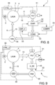
Figure 8 is a diagrammatic view of a closed drying circuit with heat pump of a tumble dryer according to the invention, -
Figure 9 is a diagrammatic view of a closed drying circuit with an electric resistor of a tumble dryer according to the invention. - With reference to the figures, a
tumble dryer 1 comprises ahousing 2 which accommodates alaundry compartment 3 delimited by adrum structure 4, for containing the laundry to be dried, amotor 5 for moving the laundry in thelaundry compartment 3, and adrying circuit 6 which conveys a dryingair flow 15 through thelaundry compartment 3. - The
drum structure 4 comprises: - a pivoting
side wall 7 made of plastic material, extending circumferentially (but not necessarily with a precise circular shape) with respect to a rotation axis 8 (which also constitutes a central axis of the side wall 7) and having an annularrear edge 9 delimiting arear opening 10, as well as an annularfront edge 11 delimiting afront opening 12, - a stationary
rear wall 13, transverse or orthogonal to therotation axis 8 and forming:- a) an
annular receiving seat 14 which engages therear edge 9 of theside wall 7 pivotally about therotation axis 8 and so that the stationaryrear wall 13 closes therear opening 10 of the pivotingside wall 7, and - b) a
perforation 22 to allow the dryingair flow 15 to pass through the stationaryrear wall 13 in thelaundry compartment 3 delimited by the pivotingside wall 7 and the stationaryrear wall 13,
- a) an
- a plurality of
rear support rollers 16 pivotally supported by a stationaryrear support portion 17, and a plurality offront support rollers 18 pivotally supported by a stationaryfront support portion 19,
wherein theside wall 7 forms arear support track 20 resting on therear support rollers 16 and afront support track 21 resting on thefront support rollers 18, so as to support theside wall 7 pivotally about therotation axis 8 with respect to the stationaryrear wall 13 and with respect to the rear 17 and front 19 stationary support portions. - Thanks to the material separation of the
side wall 7 from therear wall 13, theplastic side wall 7 can be manufactured using a single injection or blow molding process, without additional joining, gluing or welding of components, significantly simplifying manufacturing and reducing the cost of thedrum structure 4. - Thanks to the collaboration and combination of the
pivoting side wall 7 with the stationaryrear wall 13, which together form a laundry drum, theperforation 22 for the entry of the dryingair 15 into thelaundry compartment 3 remains stationary, eliminating the radial fan effect and reducing noise and allowing a configuration and distribution of theperforation openings 22 aimed at directing theair flow 15 and distributing the flow rate as desired. - Due to the relative movement between the stationary
rear wall 13 and the pivotingside wall 7, the tendency for part of the laundry to remain stationary in the corner between theside wall 7 and therear wall 13 is also reduced and a further component of movement and opening of the items of laundry inside thelaundry compartment 3 is generated. - Thanks to the provision of two distinct support tracks,
front 21 and rear 20, and two groups of support rollers,front 18 and rear 16, the invention obviates the need to provide a cantilever support for the laundry drum (meaning the set of rear 13 and lateral 7 walls) via a support shaft or hub and the relative fastenings and reinforcements to the rear wall. The absence of these components (present in embodiments of the prior art) also allowsperforation openings 22 to be provided even in the central region (otherwise occupied) of therear wall 13. - According to an embodiment, the
rear wall 13 is made of plastic material, advantageously fiber-reinforced plastic material, and preferably formed by injection molding. This further reduces the material and manufacturing costs of thedrum structure 4, allowing, for example, the rear wall to be made by a single injection molding process during which theperforation openings 22 are also made without wasting material and without any shearing or punching processes, as well as the annular receivingseat 14. - The
rear wall 13 comprises acircular bottom portion 23, e.g., concave towards the inside of thelaundry compartment 3 or substantially flat, delimited by the annular receivingseat 14 and in which bottom portion theentire perforation 22 is formed. - The
bottom portion 23 is imaginarily divided by a firsthorizontal diameter 24 and a secondvertical diameter 25, perpendicular to each other and radial with respect to therotation axis 8, into: - a first left upper quadrant 26_1 (seen from the inside of the laundry compartment 3),
- a second right upper quadrant 26_2 (seen from the inside of the laundry compartment 3),
- a third left lower quadrant 26_3 (seen from the inside of the laundry compartment 3),
- a fourth right lower quadrant 26_4 (seen from the inside of the laundry compartment 3).
- According to an embodiment, a total "upper" opening area of the
perforation 22 in the first quadrant 26_1 and second quadrant 26_2 put together is smaller than a total "lower" opening area of theperforation 22 in the third quadrant 26_3 and fourth quadrant 26_4 put together, in particular when the dryingair 15 in thedrying circuit 6 is conveyed from below underneath theside wall 7 upwards to therear wall 13. - Alternatively, a total "upper" opening area of the
perforation 22 in the first quadrant 26_1 and second quadrant 26_2 put together is greater than a total "lower" opening area of theperforation 22 in the third quadrant 26_3 and fourth quadrant 26_4 put together, in particular when the dryingair 15 in thedrying circuit 6 is conveyed from above over theside wall 7 downwards to therear wall 13. - This makes it possible to compensate for the influence of the arrival direction of the
air flow 15 upwards to therear wall 13 and to make theair flow 15 in thelaundry compartment 3 uniform. - Likewise, according to an embodiment, a total "left" opening area of the
perforation 22 in the first quadrant 26_1 and third quadrant 26_3 put together is smaller than a total "right" opening area of theperforation 22 in the second quadrant 26_2 and fourth quadrant 26_4 put together, in particular when the dryingair 15 in thedrying circuit 6 is conveyed from the right side of theside wall 7 to the left (again seen from inside the laundry compartment 3) to therear wall 13. - Alternatively, according to an embodiment, a total "left" opening area of the
perforation 22 in the first quadrant 26_1 and third quadrant 26_3 put together is greater than a total "right" opening area of theperforation 22 in the second quadrant 26_2 and fourth quadrant 26_4 put together, in particular when the dryingair 15 in thedrying circuit 6 is conveyed from the left side of theside wall 7 to the right (seen from inside the laundry compartment 3) to therear wall 13. - According to an embodiment, the annular receiving
seat 14 comprises anannular groove 27 facing the annularrear edge 9 and forming and accommodating afront gasket 28 in sliding contact (with low friction) with the rearannular edge 9. Thefront gasket 28 has the function of sealing the rotating coupling of the air circuit, consisting of theside wall 7 andstationary wall 13, and may comprise an elastically yielding base (for generating an elastic contact preload and compensating for geometric tolerances), fastened to thestationary wall 13, and which supports a sealing gasket, in frontal contact with theside wall 7 and made of a low-friction material, for example wool-based felt or synthetic fibers. - The
annular groove 27 is delimited by twowalls 29 which flank the rearannular edge 9 and stabilize its circular shape in case of unwanted deformations due to uneven and unbalanced loads of laundry. - According to an embodiment, the
rear support portion 17 is directly formed by therear wall 13 and, thus therear support rollers 16 are directly supported by therear wall 13. Therear support rollers 16 comprise two rollers arranged in the samerear support plane 30 orthogonal to therotation axis 8 in a symmetrical lower-side position with respect to a vertical plane radial to therotation axis 8. - According to an embodiment, the
drum structure 4 comprises arear cover 31 made of a plastic material, e.g. fiber-reinforced plastic material, connected to therear wall 13 on a rear side of thedrum structure 4, opposite to theside wall 7, and together with therear wall 13 defining arear air channel 32 of the dryingcircuit 6 in communication with theperforation 22 of therear wall 13. - The fact that the
rear air channel 32 is made of plastic material further reduces the weight and costs for the material and for manufacturing thedrum structure 4, reduces risks of corrosion and facilitates the assembly of the components exclusively made of synthetic material. - According to embodiments, the
rear cover 32 may be mounted on the rear wall by: - shape coupling (bayonet or threaded type, or by mutual insertion of special coupling guides formed on the
rear cover 32 and on the rear wall 13), or - interference coupling (e.g., by fastening clips, snap coupling or screws), or
- gluing or welding, e.g., ultrasonic.
- According to an embodiment, the
rear cover 32 is formed in one piece with the rear wall, by injection molding. - According to an embodiment, the
rear cover 32 has: - a half-
shell shape 33 defining an internal cavity intended to face therear wall 13, or - a first
tubular portion 34 and a second half-shell-shapedportion 33 defining an internal cavity intended to face therear wall 13. - According to an embodiment, the
side wall 7 forms one or more dragging paddles 35 protruding towards the inside of thelaundry compartment 3 and formed in one piece with theside wall 7, e.g., by injection molding or blow molding. This reduces the number of individual components to be assembled and the manufacturing costs. - The one or more dragging paddles 35 are formed by local recesses of the
side wall 7 which form concave cavities on the radially outer surface of theside wall 7 and corresponding convex protrusions on the radially inner surface of theside wall 7. - Advantageously, the one or more dragging paddles 35 do not extend up to the
rear edge 9 and do not extend up to thefront edge 11, so as not to negatively interfere with the closing function of thelaundry compartment 3 on the rear and/or front sides of theside wall 7. - With further advantage, the one or more dragging paddles 35 extend into a central region of the axial extension of the
side wall 7, between thefront support track 21 and therear support track 20, without however reaching the front 21 and rear 20 support tracks, so as not to negatively interfere with the rolling of the front 18 and rear 16 support rollers. - According to an embodiment, the dragging paddles 35 (and/or the entire inner surface of the
side wall 7 in the extension region of the dragging paddles 35) have a shape that tapers (or has converging draft angles), going radially towards therotation axis 8. This allows theside wall 7 to be manufactured particularly quickly and cheaply, by injection molding with the aid of an internal mold radially retractable towards the inside. - Likewise, according to an embodiment, the dragging paddles (and/or the entire inner surface of the
side wall 7 in the extension region of the dragging paddles 35) have a shape that widens (or has diverging draft angles), going radially outwards. This allows theside wall 7 to be manufactured particularly quickly and cheaply, by injection molding with the aid of an external mold that can be radially opened/retracted towards the outside. - In this context, it is particularly advantageous that the
side wall 7 forms exactly two draggingpaddles 37 in diametrically opposite positions with respect to a central radial plane 36 (preferably of symmetry) of theside wall 7. This makes it possible to use only two opposing external mold "cheeks" that are closable and openable in a direction orthogonal to the centralradial plane 36. - According to an embodiment, the
side wall 7 forms acylindrical pulley seat 37, facing radially outwards and delimited bilaterally by two annularparallel ribs 38 for securely accommodating abelt 39 for the transmission of a rotary motion from theelectric motor 5 to theside wall 7. Thepulley seat 37 and the two annularparallel ribs 38 are also made of plastic material and formed in one piece with theside wall 7. This reduces the number of individual components to be assembled and the manufacturing costs. - According to an alternative embodiment, the
side wall 7 can form a ring gear (not shown in the figures) adapted to be engaged by a gear for the transmission of a rotary motion from theelectric motor 5 to theside wall 7. The ring gear is also made of plastic material and formed in one piece with theside wall 7. - According to an embodiment, the
rear support track 20 and thefront support track 21 have a circular cylindrical shape, whereas theside wall 7 has a non-cylindrical shape, e.g. a shape with one or more frustoconical segments and/or one or more steps formed between neighboring frustoconical and/or cylindrical segments. - The rear 20 and
front 21 support tracks with a locally cylindrical shape in the overallnon-cylindrical side wall 7 create thickened sections of material and/or with local curvature or angulation which act as stiffening ribs of the side wall 7 (compensating for the reduced stiffness of the plastic material with respect to the stiffness of steel sheet drums) and can be easily made by injection molding. - According to an embodiment, the
drum structure 4 or thetumble dryer 1 comprises a stationaryfront wall 40, transverse or orthogonal to therotation axis 8 and forming an annularfront receiving seat 41 which engages thefront edge 11 of theside wall 7 pivotally about therotation axis 8 without obstructing thefront opening 12 of the pivotingside wall 7. - According to an embodiment, the
front receiving seat 41 comprises anannular groove 42 facing the annularrear edge 11 and forming or accommodating a (further)front gasket 28 in sliding contact (with low friction) with the frontannular edge 11. Theannular groove 42 is delimited by twowalls 43 which flank the rearannular edge 11 and stabilize its circular shape in case of unwanted deformations due to uneven and unbalanced loads of laundry. - According to an embodiment, the
front support portion 19 is directly formed by the stationaryfront wall 40 and, thus thefront support rollers 18 are directly supported by thefront wall 40. Thefront support rollers 18 comprise two rollers arranged in the samefront support plane 44 orthogonal to therotation axis 8 in a symmetrical lower-side position with respect to a vertical plane radial to therotation axis 8. - In a known way, the
front opening 12 is openable and closable by afront door 45 of thetumble dryer 1. - The invention described up to now is advantageously implementable in
tumble dryers 1, e.g. of the closed air circuit with electric resistor or heat pump type. - In the embodiment with a
closed drying circuit 6 with electric resistor (Figure 9 ), the dryingair 15 is conveyed by means of a fan 46 (actuated by a motor 47), heated by means of anelectric resistor 48 and directed into thelaundry compartment 3, where, as it passes through the wet laundry, it causes the water contained in the fabrics to evaporate. After leaving thelaundry compartment 3, the dryingair 15 laden with moisture passes through aheat exchanger 49, where it is cooled, for example, by means of a flow of cold water orfresh air 50 conveyed by means of a second fan (operated preferably but not necessarily by means of the same electric motor 47), so as to remove the moisture therefrom by means of condensation. The condensate is collected in a removable condensation container or discharged by a discharge pump and/or together with the cooling water. The dehumidified dryingair 15 is then suctioned again by thefan 46, heated by means of theelectrical resistor 48 and re-directed into thelaundry compartment 3. Upstream of the heat exchanger 49 (in which the moisture is removed) alint filter 51 is arranged. - In the embodiment with a
closed drying circuit 6 with heat pump (Figure 8 ), upon exiting thelaundry compartment 3, the dryingair 15 laden with moisture passes through a first (cold)heat exchanger 52 formed by an evaporator 52' of the heat pump, where theair 15 is cooled so as to remove the moisture therefrom by condensation. Also in this case the condensate may be collected in a removable condensation container or discharged, e.g. by a discharge pump. The dehumidified and cooled dryingair 15 is then directed into a second (hot) heat exchanger formed by aheat pump condenser 53, where the air is heated. The dehumidified and heated air is suctioned by means of afan 46 and directed again into thelaundry compartment 3 so as to continue extracting moisture from the laundry. - The heat pump further comprises a
compressor 54 which suctions a coolant fluid through the evaporator 52', where the fluid itself evaporates at low pressure (absorbing the heat of the drying air 15), compresses the coolant fluid and pushes it into thecondenser 53 where the compressed and heated coolant fluid condenses and cools at high pressure (releasing its heat to the drying air 15). After thecondenser 53, the coolant fluid passes through anexpansion valve 55 which reduces the pressure of the fluid with consequent lowering of the temperature and, then, returns again into the evaporator 52', restarting the cycle. Also in the embodiment with a heat pump, upstream of the first heat exchanger 52 (evaporator 52'), alint filter 51 is arranged. - The
tumble dryer 1 comprises anelectronic control system 56 in signal connection with and controlling the electric power supply of the individual functional groups of the tumble dryer 1 (Figures 8 and 9 ). -
-
tumble dryer 1 -
housing 2 -
laundry compartment 3 - drum
structure 4 -
motor 5 - drying
circuit 6 -
side wall 7 -
rotation axis 8 - annular
rear edge 9 -
rear opening 10 - annular
front edge 11 -
front opening 12 -
rear wall 13 - annular receiving
seat 14 - drying
air flow 15 -
rear support rollers 16 -
rear support portion 17 -
front support rollers 18 -
front support portion 19 -
rear support track 20 -
front support track 21 -
perforation 22 -
bottom portion 23 - first
horizontal diameter 24 - second
vertical diameter 25 - first left upper quadrant 26_1
- second right upper quadrant 26_2
- third left lower quadrant 26_3
- fourth right lower quadrant 26_4
-
annular groove 27 -
front gasket 28 -
walls 29 -
rear support plane 30 -
rear cover 31 -
rear air channel 32 - half-
shell 33 -
tubular portion 34 - dragging paddles 35
- central
radial plane 36 -
pulley seat 37 -
parallel ribs 38 -
belt 39 - stationary
front wall 40 - front receiving
seat 41 -
annular groove 42 -
walls 43 -
front support plane 44 -
front door 45 -
fan 46 -
motor 47 -
electrical resistor 48 -
heat exchanger 49 -
fresh air flow 50 -
lint filter 51 -
first heat exchanger 52 - evaporator 52'
- second heat exchanger,
condenser 53 -
compressor 54 -
expansion valve 55 -
control system 56
Claims (16)
- A drum structure (4) for a tumble dryer (1) of the type comprising a laundry compartment (3) for containing the laundry to be dried and a drying circuit (6) which conveys a drying air flow (15) through the laundry compartment (3), wherein the drum structure (4) comprises:- a pivoting side wall (7) made of a plastic material, being tubular in shape, extending circumferentially about a rotation axis (8) and having an annular rear edge (9) delimiting a rear opening (10), as well as an annular front edge (11) delimiting a front opening (12),- a stationary rear wall (13), transverse to the rotation axis (8) and forming:- an annular receiving seat (14) which engages the rear edge (9) of the side wall (7) pivotally about the rotation axis (8) and so that the stationary rear wall (13) closes the rear opening (10) of the pivoting side wall (7), and- a perforation (22) to allow the drying air flow (15) to pass through the stationary rear wall (13) in the laundry compartment (3) delimited by the pivoting side wall (7) and the stationary rear wall (13),- a plurality of rear support rollers (16) pivotally supported by a stationary rear support portion (17), and a plurality of front support rollers (18) pivotally supported by a stationary front support portion (19),wherein the side wall (7) forms a rear support track (20) resting on the rear support rollers (16) and a front support track (21) resting on the front support rollers (18), so as to support the side wall (7) pivotally about the rotation axis (8) with respect to the stationary rear wall (13) and with respect to the rear (17) and front (19) stationary support portions.
- A drum structure (4) according to claim 1, wherein the rear wall (13) is made of a plastic material.
- A drum structure (4) according to claim 1 or 2, wherein the rear wall (13) comprises a circular bottom portion (23), delimited by the annular receiving seat (14) and in which bottom portion the entire perforation (22) is formed,wherein the bottom portion (23) is imaginatively divided by a first horizontal diameter (24) and a second vertical diameter (25), perpendicular to each other and radial with respect to the rotation axis (8), into:- a first left upper quadrant (26_1),- a second right upper quadrant (26_2),- a third left lower quadrant (26_3),- a fourth right lower quadrant (26_4),seen from the inside of the laundry compartment (3),wherein a permeability of the perforation (22) expressed as the ratio between the passage opening area and the total quadrant area in at least one or more of the first, second, third, and fourth quadrants differs from the permeability of the perforation (22) in at least another of the first, second, third, and fourth quadrants.
- A drum structure (4) according to claim 3, comprising a part of the drying circuit (6) which guides the drying air (15) from below, underneath the side wall (7), upwards to the rear wall (13),
wherein a total "upper" opening area of the perforation (22) in the first quadrant (26_1) and in the second quadrant (26_2) put together is smaller than a total "lower" opening area of the perforation (22) in the third quadrant (26_3) and in the fourth quadrant (26_4) put together. - A drum structure (4) according to claim 3, comprising a part of the drying circuit (6) which guides the drying air (15) from above the side wall (7) downwards to the rear wall (13), wherein a total "upper" opening area of the perforation (22) in the first quadrant (26_1) and in the second quadrant (26_2) put together is greater than a total "lower" opening area of the perforation (22) in the third quadrant (26_3) and in the fourth quadrant (26_4) put together.
- A drum structure (4) according to claim 3, 4 or 5, comprising a part of the drying circuit (6) which guides the drying air (15) from the right side of the side wall (7) towards the left, seen from the inside of the laundry compartment (3), to the rear wall (13),
wherein a total "left side" opening area of the perforation (22) in the first quadrant (26_1) and in the third quadrant (26_3) put together is smaller than a total "right side" opening area of the perforation (22) in the second quadrant (26_2) and in the fourth quadrant (26_4) put together. - A drum structure (4) according to claim 3, 4 or 5, comprising a part of the drying circuit (6) which guides the drying air (15) from the left side of the side wall (7) towards the right, seen from the inside of the laundry compartment (3), to the rear wall (13),
wherein a total "left side" opening area of the perforation (22) in the first quadrant (26_1) and in the third quadrant (26_3) put together is greater than a total "right side" opening area of the perforation (22) in the second quadrant (26_2) and in the fourth quadrant (26_4) put together. - A drum structure (4) according to any one of the preceding claims, wherein the annular receiving seat (14) comprises an annular groove (27) facing the annular rear edge (9) and accommodating a front gasket (28) in sliding contact with the rear annular edge (9).
- A drum structure (4) according to any one of the preceding claims, wherein the rear support portion (17) is formed directly by the rear wall (13) and the rear support rollers (16) comprise two rollers arranged in a same rear support plane (30) orthogonal to the rotation axis (8) in a symmetrical position with respect to a vertical plane radial to the rotation axis (8).
- A drum structure (4) according to any one of the preceding claims, comprising a rear cover (31) made of a plastic material, connected to the rear wall (13) on a rear side of the drum structure (4), opposite to the side wall (7), and together with the rear wall (13) defining a rear air channel (32) of the drying circuit (6) in communication with the perforation (22).
- A drum structure (4) according to any one of the preceding claims, wherein the side wall (7) forms one or more dragging paddles (35) protruding towards the inside of the laundry compartment (3) and formed in one piece with the side wall (7).
- A drum structure (4) according to claim 11, wherein one or more dragging paddles (35) are formed by local recesses of the side wall (7) which form concave cavities on the radially outer surface of the side wall (7) and corresponding convex protrusions on the radially inner surface of the side wall (7).
- A drum structure (4) according to claim 11 or 12,wherein said one or more dragging paddles (35) extend into a central region of the axial extension of the side wall (7), between the front support track (21) and the rear support track (20), without however reaching the front (21) and rear (20) support tracks, and/or.wherein the one or more dragging paddles (35) have a shape that tapers going radially towards the rotation axis (8), and the outer surface of the side wall (7) in the region of the dragging paddles (35) has a shape that widens going radially outwards, and/or wherein the side wall (7) forms exactly two dragging paddles (37) in diametrically opposite positions with respect to a central radial plane (36) of the side wall (7).
- A drum structure (4) according to any one of the preceding claims, wherein the side wall (7) forms a cylindrical pulley seat (37), facing radially outwards and delimited bilaterally by two annular parallel ribs (38) for securely accommodating a belt (39) for the transmission of a rotary motion from an electric motor (5) to the side wall (7),
wherein said pulley seat (37) and the two annular parallel ribs (38) are made of a plastic material and formed in one piece with the side wall (7). - A drum structure (4) according to any one of the preceding claims, wherein the rear support track (20) and the front support track (21) have a circular cylindrical shape, whereas the side wall (7) has a non-cylindrical shape, or a shape with one or more frustoconical segments and/or one or more steps formed between adjacent frustoconical and/or cylindrical segments.
- A tumble dryer (1), comprising a drum structure (4) according to any one of the preceding claims.
Applications Claiming Priority (1)
| Application Number | Priority Date | Filing Date | Title |
|---|---|---|---|
| IT102023000020109A IT202300020109A1 (en) | 2023-09-29 | 2023-09-29 | DRUM STRUCTURE FOR CLOTH DRYER AND CLOTH DRYER |
Publications (1)
| Publication Number | Publication Date |
|---|---|
| EP4530388A1 true EP4530388A1 (en) | 2025-04-02 |
Family
ID=89158064
Family Applications (1)
| Application Number | Title | Priority Date | Filing Date |
|---|---|---|---|
| EP24201822.4A Pending EP4530388A1 (en) | 2023-09-29 | 2024-09-23 | Drum structure for a tumble dryer and tumble dryer |
Country Status (3)
| Country | Link |
|---|---|
| EP (1) | EP4530388A1 (en) |
| CN (1) | CN119736780A (en) |
| IT (1) | IT202300020109A1 (en) |
Citations (3)
| Publication number | Priority date | Publication date | Assignee | Title |
|---|---|---|---|---|
| JPH03212295A (en) * | 1990-01-18 | 1991-09-17 | Sanyo Electric Co Ltd | Dryer |
| EP2499290A1 (en) * | 2009-11-09 | 2012-09-19 | Indesit Company S.p.A. | Household laundry dryer |
| EP2990521A1 (en) * | 2014-08-29 | 2016-03-02 | Electrolux Appliances Aktiebolag | Laundry dryer |
-
2023
- 2023-09-29 IT IT102023000020109A patent/IT202300020109A1/en unknown
-
2024
- 2024-09-23 EP EP24201822.4A patent/EP4530388A1/en active Pending
- 2024-09-29 CN CN202411372342.6A patent/CN119736780A/en active Pending
Patent Citations (3)
| Publication number | Priority date | Publication date | Assignee | Title |
|---|---|---|---|---|
| JPH03212295A (en) * | 1990-01-18 | 1991-09-17 | Sanyo Electric Co Ltd | Dryer |
| EP2499290A1 (en) * | 2009-11-09 | 2012-09-19 | Indesit Company S.p.A. | Household laundry dryer |
| EP2990521A1 (en) * | 2014-08-29 | 2016-03-02 | Electrolux Appliances Aktiebolag | Laundry dryer |
Also Published As
| Publication number | Publication date |
|---|---|
| IT202300020109A1 (en) | 2025-03-29 |
| CN119736780A (en) | 2025-04-01 |
Similar Documents
| Publication | Publication Date | Title |
|---|---|---|
| EP3309291B1 (en) | Clothes dryer | |
| EP2990519B1 (en) | Laundry dryer | |
| KR101210712B1 (en) | Damper unit for Dryer | |
| EP2990521B1 (en) | Laundry dryer | |
| EP1984553B1 (en) | Domestic clothes drier with twin fan | |
| US3831292A (en) | Condenser apparatus | |
| US3875679A (en) | Condenser apparatus | |
| JP5457807B2 (en) | Commercial laundry dryer | |
| US12129587B2 (en) | Combination washing and drying appliance having an airflow system contained within an outer tub | |
| EP4530388A1 (en) | Drum structure for a tumble dryer and tumble dryer | |
| EP2631353B1 (en) | Rotary-drum laundry dryer | |
| US3858330A (en) | Condenser apparatus | |
| CN110924042B (en) | Clothes treating apparatus | |
| KR100233496B1 (en) | Clothes dryer | |
| US3398465A (en) | Clothes dryer with fabric deflecting bulkhead | |
| US11592030B2 (en) | Fan assembly and washing machine having the same | |
| EP3943656B1 (en) | Laundry treatment device | |
| EP3249093B1 (en) | Laundry dryer | |
| EP2499287B1 (en) | Household laundry dryer | |
| EP2499290B1 (en) | Household laundry dryer | |
| KR100565658B1 (en) | Drying duct of drum washing machine | |
| CN222205811U (en) | Clothes dryer | |
| US20210071346A1 (en) | Vortex dryer appliance | |
| KR20250098852A (en) | A laundry treating apparatus | |
| KR20250098842A (en) | Laundry Treating Apparatus |
Legal Events
| Date | Code | Title | Description |
|---|---|---|---|
| PUAI | Public reference made under article 153(3) epc to a published international application that has entered the european phase |
Free format text: ORIGINAL CODE: 0009012 |
|
| STAA | Information on the status of an ep patent application or granted ep patent |
Free format text: STATUS: THE APPLICATION HAS BEEN PUBLISHED |
|
| AK | Designated contracting states |
Kind code of ref document: A1 Designated state(s): AL AT BE BG CH CY CZ DE DK EE ES FI FR GB GR HR HU IE IS IT LI LT LU LV MC ME MK MT NL NO PL PT RO RS SE SI SK SM TR |
|
| STAA | Information on the status of an ep patent application or granted ep patent |
Free format text: STATUS: REQUEST FOR EXAMINATION WAS MADE |
|
| 17P | Request for examination filed |
Effective date: 20250903 |