EP4530219A1 - Beverage preparation capsule and method of producing the same - Google Patents
Beverage preparation capsule and method of producing the same Download PDFInfo
- Publication number
- EP4530219A1 EP4530219A1 EP23200053.9A EP23200053A EP4530219A1 EP 4530219 A1 EP4530219 A1 EP 4530219A1 EP 23200053 A EP23200053 A EP 23200053A EP 4530219 A1 EP4530219 A1 EP 4530219A1
- Authority
- EP
- European Patent Office
- Prior art keywords
- capsule
- side wall
- scoring line
- main body
- along
- Prior art date
- Legal status (The legal status is an assumption and is not a legal conclusion. Google has not performed a legal analysis and makes no representation as to the accuracy of the status listed.)
- Pending
Links
Images

Classifications
-
- B—PERFORMING OPERATIONS; TRANSPORTING
- B65—CONVEYING; PACKING; STORING; HANDLING THIN OR FILAMENTARY MATERIAL
- B65D—CONTAINERS FOR STORAGE OR TRANSPORT OF ARTICLES OR MATERIALS, e.g. BAGS, BARRELS, BOTTLES, BOXES, CANS, CARTONS, CRATES, DRUMS, JARS, TANKS, HOPPERS, FORWARDING CONTAINERS; ACCESSORIES, CLOSURES, OR FITTINGS THEREFOR; PACKAGING ELEMENTS; PACKAGES
- B65D85/00—Containers, packaging elements or packages, specially adapted for particular articles or materials
- B65D85/70—Containers, packaging elements or packages, specially adapted for particular articles or materials for materials not otherwise provided for
- B65D85/804—Disposable containers or packages with contents which are mixed, infused or dissolved in situ, i.e. without having been previously removed from the package
- B65D85/8043—Packages adapted to allow liquid to pass through the contents
Definitions
- the present invention relates to a beverage capsule for preparing a beverage in a beverage preparation machine.
- the present invention further relates to a method of producing such a capsule.
- the present invention further relates to a use of such a capsule in a beverage preparation machine.
- Capsules for beverage preparation machines are well known in the art. Capsules are typically used for on demand dispensing of beverages like coffee, tea, hot chocolate or the like and enjoy popularity due to their fresh tasting, variability of flavors and the convenience of the beverage preparation.
- Beverage preparation depends on a high number of parameters and effects, some of which can be attributed to the design of the capsule.
- a beverage capsule configured for use in a beverage preparation machine and in particular in a capsule beverage preparation machine.
- the capsule is configured for preparing a beverage upon injection of liquid into the capsule and dispensing the beverage through the capsule.
- the capsule comprises a cup-shaped main body including a bottom wall and a side wall.
- the capsule further comprises a sealing lid connected to the side wall, wherein the lid, the bottom wall, and the side wall define a volume or compartment for holding beverage preparation ingredients therein.
- the capsule further comprises a scoring line extending on the side wall and being configured for weakening the side wall and/or extending on the bottom wall and being configured for weakening the bottom wall.
- the capsule according to the present invention is based at least partially on the idea that by including a scoring line extending on the side wall and/or the bottom wall, the side wall and/or the bottom wall can be weakened.
- the expressions "weakening" or “weakened” may be understood as any material deficiency or combination of deficiencies which may result in, for example, a reduced strength of the material. For instance, and preferably, the thickness of the material in the region of the scoring line, may be reduced by at least one third.
- the capsule is further based on the idea that such a weakened wall can be torn open, preferably by hand, to gain access to the beverage preparation ingredients contained inside the capsule.
- the capsule is further based on the idea that once the capsule is opened, the beverage preparation ingredients can be removed from the opened capsule and the beverage preparation ingredients can be disposed or composted separately from the opened capsule. If the capsule is made of recyclable material such as a recyclable aluminum alloy material, the opened capsule can be recycled, for example at a consumer collection station as part of a waste disposal and recycle system.
- the capsule according to the present invention proposes an eco-friendly way of using capsules in a beverage preparation machine.
- the capsule according to the present invention is particularly intended for use in a capsule beverage preparation machine as known, for example, from EP 0 512 470 A1 or EP 2 919 628 A1 which are incorporated by reference herein in their entirety.
- the capsule according to the present invention is configured such that it can be used as an alternative to known capsules typically used in such a machine.
- the scoring line is produced by means of laser scoring and/or mechanical cutting or other suitable techniques.
- the scoring line may be produced prior to or after the insertion of the beverage preparation ingredients.
- the scoring line is produced after deep drawing the main body.
- the scoring line extends along between 30% and 100%, preferably between 30% and 90%, more preferably between 50% and 85%, even more preferably between 60% and 85%, of a periphery of the side wall; and/or at least along 50%, preferably at least around 60%, of a periphery of the side wall; and/or along 90% or less, preferably along 85% or less, more preferably along 75% or less, of a periphery of the side wall.
- the scoring line may extend along the entire side wall or a portion thereof, as the case may be.
- the scoring line extends in a circumferential direction and/or in a longitudinal direction of the side wall.
- the circumferential direction may be measured along a circumference of the capsule.
- the longitudinal direction may be measured along a longitudinal axis of the capsule.
- the longitudinal axis may be an axis extending from a bottom part of the capsule, such as the bottom wall of the main body, to a top part of the capsule, such as the lid of the capsule.
- the scoring line extends along between 30% and 100%, preferably between 30% and 90%, more preferably between 50% and 85%, even more preferably between 60% and 85%, of a circumferential and/or longitudinal dimension of the side wall; and/or at least along 50%, preferably at least around 60%, of a circumferential and/or longitudinal dimension of the side wall; and/or along 90% or less, preferably along 85% or less, more preferably along 75% or less, of a circumferential and/or longitudinal dimension of the side wall.
- the scoring line extends in circumferential direction of the side wall, preferably in a direction substantially parallel to the sealing lid.
- the scoring line is arranged closer to the bottom wall than to the sealing lid. More preferably, the scoring line is arranged at a distance of not more than one half or one third of a height of the capsule when measured from the capsule's bottom end, wherein the height is measured between the bottom wall and the sealing lid along the capsule's longitudinal axis.
- the scoring line is such that the capsule remains in one piece after the capsule is opened along the scoring line.
- the scoring line extends at least 360° around a longitudinal axis of the capsule, preferably at least 450°, more preferably at least 540° or 720°.
- the scoring line extends in a substantially spiral shape, preferably a substantially helical shape on the side wall.
- the scoring line may extend multiple times around the side wall, for example in spiral or helical manner.
- the scoring line may extend in a longitudinal direction of the side wall, preferably along the entire side wall, preferably in a substantially perpendicular direction to the sealing lid.
- the scoring line may extend from the side wall onto the bottom wall and more preferably onto a central portion thereof.
- the scoring line may extend not only on the side wall but may extend further onto the bottom wall and preferably onto a central portion thereof.
- the scoring line may extend onto a flange of the side wall.
- the flange may be formed proximate to the lid and may be configured such that the capsule can be clamped into a capsule holder of a capsule beverage preparation machine as know, for example from EP 0 512 470 A1 or EP 2 919 628 A1 mentioned earlier.
- the scoring line extends onto the flange for forming a pull tab on the flange, the pull tap being configured for tearing open the side wall along the scoring line.
- the flange or pull tap may be used as a handle or grasping section to pull open the side wall along the scoring line.
- the capsule comprises more than one scoring line such as multiple scoring lines.
- the capsule may include two scoring lines, preferably extending in parallel to one another.
- the two scoring lines extend in the longitudinal direction of the side wall and preferably extend along the entire side wall and further onto the flange and/or the bottom wall of the main body.
- the two scoring lines may form a flap or strap on the side wall which can be torn open using the flange as a pull tap.
- the scoring line or portions thereof may be arranged on an interior or internal face of the side wall, the interior or internal face being a face facing the beverage preparation ingredients inside the capsule.
- the scoring line as a whole or portions thereof may not be visible from outside of the capsule.
- the scoring line forms a push section.
- the push section may be configured for pushing the side wall inwardly (i.e., in an inward direction towards the beverage preparation ingredients) such that upon pushing the push section, the side wall is torn open along the scoring line.
- the push section is configured for inserting a finger or a nail of a user of the capsule.
- the push section may have a wave-like or arcuate shape indicating a position of the finger or nail of the user to be inserted.
- the push section may be visible from outside of the capsule.
- the push section may be formed on an exterior or outer face of the side wall.
- the remaining section or sections of the scoring line may be formed on an interior or inner face of the side wall.
- a depth of the scoring line is in a range between about 30% and about 80%, preferably between about 50% and about 70%, of a thickness of the side wall.
- the depth may be measured in a direction perpendicular to an interior and/or exterior face of the side wall.
- a width of the scoring line is in a range between 100 micrometers and 500 micrometers, preferably between 200 micrometers and 300 micrometers.
- the width of the scoring line may be adjustable by the machine cutting and/or laser scoring technique used to produce the scoring line.
- a width and/or a depth of the scoring line may be constant or may vary along the scoring line, as desired.
- the capsule comprises a depression region arranged on the main body.
- the depression region may be configured for handling and/or manipulating the main body, in particular for handling and/or manipulating the main body such that upon manipulation of the main body, the side wall is torn open along the scoring line.
- the depression region is configured for inserting a finger or nail of a user of the capsule.
- the depression region may be a recess or dent formed on an exterior face of the side wall and extending inwardly such that a finger or nail can be comfortably accommodated inside the depression region.
- a depth of the depression region may be at least 3 mm and a width of the depression region may be at least 5 mm so that the finger or nail can be comfortably put into the depression region.
- the capsule comprises a pull tab arranged on the main body.
- the pull tap may be configured for applying a pulling force on a portion of the main body such that upon pulling on the pull tap, the side wall can be torn open along the scoring line.
- the scoring line may divide the side wall into a top and bottom section and the depression region and/or the pull tap may be arranged in the bottom section.
- the pull tab and the main body may be formed as separate components.
- the pull tab may be connected and/or attached to the main body by means of suitable manufacturing techniques, such as ultrasonic welding or heat welding.
- the scoring line is configured such that the side wall is openable manually, preferably without using tools, more preferably by hand.
- an opening of the capsule can be assisted by using the depression region, the pull tap, the push section, the flange, or combinations thereof.
- the scoring line of the capsule is configured to withstand a pressure difference between an outside and an inside of the capsule during preparation of the beverage.
- the scoring line is configured to withstand a pressure difference of at least 4 bar, more preferably of at least 8 bar, more preferably of at least 10 bar, during preparation of the beverage.
- the pressure differences are typical pressure differences used in a capsule beverage preparation machine as known, for example from EP 0 512 470 A1 or EP 2 919 628 A1 mentioned earlier.
- the main body has a cylindrical shape or a frustoconical shape or a domical shape or a frustodomical shape.
- the side wall has a frustoconical shape and the bottom wall has a flat or domical shape.
- the shape of the main body may generally be such that the capsule according to the present invention can be used in a capsule beverage preparation machine as described, for example in EP 0 512 470 A1 or EP 2 919 628 A1 .
- the capsule further comprises a coating, preferably a spray coating and/or lacquer, that is applied over at least a segment of the scoring line.
- the coating may be configured for preventing sharp edges during opening of the side wall.
- the main body and/or the lid are made of a non-compostable material and/or a recyclable material, preferably a recyclable aluminum alloy material.
- compostable may be understood as any material that complies with certain compostability standards.
- industrial compostability is defined in European Norm EN 13432.
- Home compostability conditions are adapted based on national standards within certain testing specifications, such as TÜV testing specifications. Materials or products compliant with these standards can be recognized, for example, by a conformity mark stating their home compostability.
- Some examples of home compostability certifications at a national level include, but are not limited to, the following.
- the certifier TÜV AUSTRIA BELGIUM offers such a home compostability certification scheme
- DIN CERTCO offers a certification for home compostability according to the Australian standard AS 5810. Italy has a national standard for composting at ambient temperature, UNI 11183:2006.
- the French Standard "NF T 51-800 Plastics - Specifications for plastics suitable for home composting” was introduced. This standard is covered in the DIN CERTCO scheme.
- Another aspect of the present invention which may form an independent aspect of the present invention, relates to a use of a capsule in a beverage preparation machine and in particular to a use of a capsule according to the first aspect or embodiments thereof in a beverage preparation machine.
- the use of the capsule includes the steps of: inserting the capsule into a beverage preparation machine; preparing a beverage by injecting liquid into the capsule, whereby liquid is mixed with beverage preparation ingredients contained inside the capsule for forming a beverage that is dispensed by the machine; removing the capsule from the beverage preparation machine; and manipulating the capsule such that the capsule opens along the scoring line.
- the step of manipulating the capsule is performed manually, preferably without using tools, more preferably by hand.
- the method further comprises: after opening the capsule along the scoring line, separating the beverage preparation ingredients from the opened capsule for disposing the same.
- the capsule remains in one piece after opening the capsule.
- the step of preparing a beverage further includes the steps of: piercing the bottom wall of the main body for forming an opening in the bottom wall; injecting liquid through the bottom wall whereby liquid is mixed with beverage preparation ingredients contained inside the capsule; and dispensing the beverage through the lid.
- a further aspect of the present invention which may form an independent aspect of the present invention, relates to a method of producing a capsule and in particular a capsule according to the first aspect and embodiments thereof.
- the method includes the steps of: producing a cup-shaped main body having a bottom wall and a side wall, preferably wherein producing the cup-shaped main body includes the step of deep drawing a sheet material, preferably a sheet material made of a recyclable aluminum alloy material; inserting beverage preparation ingredients into the main body; sealing an opening of the main body by connecting a lid to the main body; and producing a scoring line on the side wall such that the side wall is weakened by the scoring line and/or on the bottom wall such that the bottom wall is weakened by the scoring line.
- the step of producing the scoring line is done prior to or after inserting the beverage preparation ingredients.
- the scoring line is produced by means of laser scoring and/or mechanical cutting or another suitable technique.
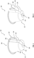
- FIG. 1 shows a schematic view of an example of a beverage capsule 10.
- the beverage capsule 10 is configured for preparing a beverage such as coffee, tea, hot chocolate, or the like upon injecting liquid into the capsule 10.
- the beverage capsule 10 is particularly suited to be used in connection with a capsule beverage preparation machine such as described in, for example, EP 0 512 470 A1 or EP 2 919 628 A1 .
- the beverage capsule 10 may be a single-serve capsule.
- the capsule 10 includes a cup-shaped main body 12.
- the main body 12 includes a bottom wall 14 and a side wall 16.
- the bottom wall 14 and the side wall 16 together form a receptacle for holding beverage preparation ingredients.
- the side wall 16 delimits an opening or mouth.
- the opening or mouth is closed by a sealing lid 18.
- the sealing lid 18 is sealingly connected to the side wall 16 such that the sealing lid 18, the side wall 16 and the bottom wall 14 together form a compartment for holding beverage preparation ingredients therein.
- the main body 12 has a generally cylindrical or frusto-conical or domical or frusto-domical shape, in particular a combination of different sections of such shapes.
- the shape of the main body 12 may be similar to the shape described in, for example EP 2 919 628 A1 , EP 0 919 628 A1 , EP 0 512 468 A1 , EP 0 512 470 A1 , EP 1 646 305 A1 , or EP 1 165 398 A1 , all of which are incorporated by reference herein in their entirety.
- the bottom wall 14 has a convex or frusto-conical shape with a central portion 20, which may be generally flat, concave or convex.
- the bottom wall 14 is configured to be pierced by an opener of a capsule preparation machine as described in, for example the aforementioned EP 2 919 628 A1 .
- the side wall 16 forms a flange 22 proximate to the lid 18.
- the flange 22 is configured such that the capsule 10 can be clamped into a capsule holder of a capsule beverage preparation machine as described in, for example the aforementioned EP 2 919 628 A1 .
- the lid 18 is configured to be pierced by a piercing plate, such as a pyramid plate which is usually used in the above mentioned capsule beverage machine.
- the piercing plate such as a pyramid plate, is configured for creating a plurality of openings in the lid 18.
- Pyramid plates include a plurality of reliefs and recessed (pyramid-like) elements. These elements are configured to tear open the lid for creating a plurality of openings in the lid under the effect of rising pressure of the liquid injected into the capsule 10. Through these openings in the lid the beverage is dispensed.
- Pyramid plates are described, for example, in EP 0 512 470 A1 .
- the capsule 10 further includes two scoring lines 24.
- the scoring lines 24 are configured for weakening the material of the main body 12.
- the scoring lines 24 may be produced by means of laser scoring, mechanical cutting or another suitable technique, prior to or after the capsule 10 is filled with the beverage preparation ingredients.
- the scoring lines 24 may have a width in a range between 100 micrometers and 500 micrometers, preferably between 200 micrometers and 300 micrometers. The width may depend on the manufacturing technique used to produce the scoring lines 24.
- the scoring lines 24 may have a depth in a range between about 30% and about 80%, preferably between about 50% and about 70% of a thickness of the side wall 16.
- the scoring lines 24 are designed to weaken the main body 12 such that the main body 12 can be torn open at the position of the scoring lines 24, preferably without using tools, more preferably by hand.
- the two scoring lines 24 extend in a substantially longitudinal direction of the capsule 10.
- the scoring lines 24 extend in a substantially perpendicular direction to the lid 18, that is in a direction from a top to a bottom of the capsule 10.
- the scoring lines 24 extend substantially parallel to one another. In other embodiments this may not be the case.
- the scoring lines 24 extend from the side wall 16 onto the bottom wall 14, e.g. up to the central portion 20 thereof. In other embodiments this may not be the case.
- the scoring lines 24 extend from the side wall 16 onto the flange 22.
- the scoring lines 24 extend onto the flange 22 such that a pull tap 26 is formed on the flange 22.
- the pull tap 26 is configured as a handle or grasping section. By applying a pulling force on the pull tap 26, the main body 12 of the capsule 10 opens along the scoring lines 24 to provide access to the beverage preparation ingredients contained inside the capsule 10.
- the capsule 10 may be opened by pulling on the pull tap 26 and tearing open the capsule 10 along the scoring lines 24.
- the scoring lines 24 form a flap or strap 28 of material between the two scoring lines 24. Opening of the capsule 10 is done manually, preferably without using tools, more preferably by hand.
- the capsule 10 remains in one piece.
- the scoring lines 24 are arranged such that the flap or strap 28 remains attached to the main body 12.
- the flap or strap 28 remains attached to the main body 12 at the central portion 20 of the bottom wall 14. In other embodiments the attachment may be at a different location.
- the beverage preparation ingredients contained inside the capsule 10 can be removed and disposed separately from the opened capsule 10 (e.g., composted).
- the opened capsule 10, may be disposed and/or recycled.
- the main body 12 and/or the lid of the capsule 10 may be made of recyclable material such as a recyclable aluminum alloy material so that the opened capsule 10 may be recycled at a consumer collection station as part of a waste disposal and recycle system.
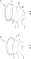
- FIG. 3 a schematic view of another example of a beverage capsule 10 is shown.
- the capsule 10 includes one scoring line 24 as compared to two scoring lines 24 shown in Figures 1 and 2 .
- the side wall 16 may include more than just one scoring line 24.
- the scoring line 24 extends in a circumferential direction of the side wall 16. In other words, the scoring line 24 extends in a substantially parallel direction to the lid 18.
- the scoring line 24 is arranged at about half a distance between the lid 18 and the bottom wall 14. In other embodiments the scoring line 24 may be arranged at a different distance.
- the scoring line 24 divides the capsule 10 in a top section 30 and a bottom section 32.
- the scoring line 24 is configured to weaken the side wall 16 such that the side wall 16 can be opened along the scoring line 24.
- the capsule 10 further includes a pull tap 34 attached to a portion of the main body 12.
- the pull tap 34 is attached to the bottom wall 14 of the capsule 10.
- the pull tap 34 may be arranged at a different location.
- the pull tap 34 is attached at the bottom section 32 of the capsule 10.
- the pull tap 34 may be monolithically formed with the main body 12 such that the pull tap 34 and the main body 12 are manufactured from a single piece.
- the pull tap 34 may be a separate part connected to the main body 12 by means of any suitable technique such as ultrasonic welding, heat welding or the like.
- the pull tap 34 is configured as a grasping section for the user of the capsule 10 to pull on the pull tap 34 for opening the capsule 10 along the scoring line 24.
- the scoring line 24 does not extend around the entire circumference of the side wall 16.
- the side wall 16 includes a section 36 that is unscored by the scoring line 24. This section 36 ensures that the capsule 10 remains in one piece once the capsule 10 has been opened along the scoring line 24. Section 36 may thus also be referred to as an "attachment section”.
- the capsule 10 is opened by tearing open the side wall 16 along the scoring line 24 using, for example, the pull tap 34 arranged on the bottom section 32 of the main body 12. As can be seen, the bottom section 32 remains attached to the top section 30 by the attachment section 36. The capsule 10 remains in one piece after opening.
- the beverage preparation ingredients contained inside the capsule 10 can be removed and disposed separately from the opened capsule 10 (e.g., composted).
- the opened capsule 10, on the other hand, may be disposed and/or recycled.
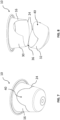
- FIG. 5 a schematic view of another example of a beverage capsule 10 is shown.
- the capsule 10 of Figure 5 is similar to the capsule 10 of Figures 3 and 4 , except that instead of a pull tap 34, the capsule 10 of Figure 5 includes a depression region 38.
- the depression region 38 is arranged on the main body 12, preferably at the bottom section 32.
- the depression region 38 is configured for handling and/or manipulating the main body 12 such that upon manipulating the main body 12, the side wall 16 is torn open along the scoring line 24.
- the depression region 38 may be a recess or dent formed on an exterior face of the side wall 16 extending inwardly. A size and a depth of the depression region 38 may be such that a finger or nail of a user of the capsule 10 can be comfortably accommodated inside the depression region 38.
- the depression region 38 may be formed during forming of the main body 12, for example during deep drawing of the main body 12.
- the capsule 10 is opened by tearing open the side wall 16 along the scoring line 24 using, for example, the depression region 38 arranged on the bottom section 32 of the main body 12.
- the bottom section 32 remains attached to the top section 30 after opening of the side wall 16 by the attachment section 36.
- the bottom section 32 and the top section 30 may not be attached to one another after opening of the capsule 10.
- the beverage preparation ingredients contained inside the capsule 10 can be removed and disposed separately from the opened capsule 10.
- the opened capsule 10, on the other hand, may be disposed and/or recycled.
- a protruding region (not shown) configured to be engaged by a finger of the user could be provided. As with the depression region 38, such protruding region could be formed during deep drawing of the main body 12. As with the depression region 38, such protruding region may assist the user in tearing open the capsule 10 along the score line 24.
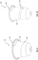
- FIG. 7 a schematic view of another example of a beverage capsule 10 is shown.
- the scoring line 24 forms a push section 40.
- the push section 40 is configured for pressing thereon with and/or inserting a finger or a nail of a user of the capsule 10 such that upon pushing the push section 40 in an inward direction, the side wall 16 is torn open along the scoring line 24.
- the push section 40 may be formed by a wave-like or arcuate section of the scoring line 24 and may indicate a position to the user for inserting the finger or nail.
- the push section 40 may have any suitable shape.
- the push section 40 may be visible from outside of the capsule 10.
- the push section 40 may be formed on an exterior face of the side wall 16.
- the remaining section or sections of the scoring line 24 may be formed on an interior face of the side wall 16. Hence, in some embodiments, only the push section 40 may be visible to a user from outside of the capsule 10.
- the push section 40 may be formed during production of the scoring line 24.
- the capsule 10 is opened by tearing open the side wall 16 along the scoring line 24, for example, by pushing in the push section 40.
- the scoring line 24 may tear open first along the push section 40.
- the scoring line 24 is arranged such that the bottom section 32 and the top section 30 remain attached to one another after opening of the capsule 10 using the attachment section 36. In other embodiments this may not be the case.
- the beverage preparation ingredients contained inside the capsule 10 can be removed and disposed separately from the opened capsule 10 (e.g., composted).
- the opened capsule 10, on the other hand, may be disposed and/or recycled.
- FIG. 9 a schematic view of another example of a beverage capsule 10 is shown.
- the scoring line 24 extends multiple times around a longitudinal axis of the capsule 10.
- the scoring line 24 extends in a substantially spiral or helical shape around the side wall 16.
- the scoring line 24 may have a pitch, similar to a pitch of a thread.
- the pitch of the scoring line 24 may be constant or may vary along the scoring line 24, as desired.
- the scoring line 24 extends onto the flange 22.
- the scoring line 24 may form a pull tap similar to the pull tap 26 explained in connection with Figures 1 and 2 .
- the capsule 10 is opened by tearing open the side wall 16 along the scoring line 24, for example, by pulling on flange 22 or the pull tap formed on the flange 22.
- the scoring line 24 is arranged such that after opening of the capsule 10, the capsule 10 remains in one piece. In other embodiments this may not be the case.
- the beverage preparation ingredients contained inside the capsule 10 can be removed and disposed separately from the opened capsule 10 (e.g., composted).
- the opened capsule 10, on the other hand, may be disposed and/or recycled.
- the capsule 10 may include one or more scoring lines 24, as desired.
- the scoring line(s) 24 may further be configured to withstand a pressure difference between an outside of the capsule 10 and an inside of the capsule 10 that typically occur during preparation of the beverage in the beverage preparation machine.
- the scoring line(s) 24 may be configured to withstand pressure differences typically used in capsule beverage preparation machines such as the one described in EP 0 512 470 A1 .
- the scoring line(s) 24 may be configured to withstand a pressure difference of at least 4 bar, preferably at least 8 bar, more preferably at least 12 bar.
- the capsule 10 may comprise a coating such as a spray coating or lacquer.
- the coating may be applied over at least a segment of the scoring line(s) 24.
- the coating may be used to prevent sharp edges during opening of the capsule 10 along the scoring line(s) 24.
Landscapes
- Engineering & Computer Science (AREA)
- Mechanical Engineering (AREA)
- Apparatus For Making Beverages (AREA)
Abstract
A capsule (10) configured for preparing a beverage upon injection of liquid into the capsule (10) is provided. The capsule (10) comprises: a cup-shaped main body (12) including a bottom wall (14) and a side wall (16), a sealing lid (18) connected to the side wall (16), wherein the lid (18), the bottom wall (14), and the side wall (16) define a compartment for holding beverage preparation ingredients therein, and a scoring line (24) extending on the side wall (16) and being configured for weakening the side wall (16).
Description
- The present invention relates to a beverage capsule for preparing a beverage in a beverage preparation machine. The present invention further relates to a method of producing such a capsule. The present invention further relates to a use of such a capsule in a beverage preparation machine.
- Capsules for beverage preparation machines are well known in the art. Capsules are typically used for on demand dispensing of beverages like coffee, tea, hot chocolate or the like and enjoy popularity due to their fresh tasting, variability of flavors and the convenience of the beverage preparation.
- Beverage preparation depends on a high number of parameters and effects, some of which can be attributed to the design of the capsule.
- In an eco-responsible approach, some existing capsules or pods are made of compostable materials. For instance, documents
WO 2016/139554 A1 ,WO 2020/114995 A1 disclose a compostable coffee pod. However, existing compostable capsules may not be ideal for use in coffee machines currently on the market, which may have been originally designed for non-compostable capsules. - It is thus an object of the present invention to provide capsule particularly for use in a beverage preparation machine that shall ensure high quality and beverage consistency during preparation of the beverage. It is a further object of the present invention to propose a capsule wherein beverage preparation ingredients can be separated from the capsule such that the beverage preparation ingredients and the capsule can be disposed separately from one another. It is a further object of the present invention to propose a capsule that is fully compatible with widespread machines designed for non-compostable capsules and provide for a proper extraction in these machines.
- These and other objects, which become apparent upon reading the description, are solved by the subject-matter of the independent claims. Further embodiments and developments are provided in the dependent claims.
- According to a first aspect of the present invention, a beverage capsule is provided. The capsule is configured for use in a beverage preparation machine and in particular in a capsule beverage preparation machine. The capsule is configured for preparing a beverage upon injection of liquid into the capsule and dispensing the beverage through the capsule. The capsule comprises a cup-shaped main body including a bottom wall and a side wall. The capsule further comprises a sealing lid connected to the side wall, wherein the lid, the bottom wall, and the side wall define a volume or compartment for holding beverage preparation ingredients therein. The capsule further comprises a scoring line extending on the side wall and being configured for weakening the side wall and/or extending on the bottom wall and being configured for weakening the bottom wall.
- The capsule according to the present invention is based at least partially on the idea that by including a scoring line extending on the side wall and/or the bottom wall, the side wall and/or the bottom wall can be weakened. The expressions "weakening" or "weakened" may be understood as any material deficiency or combination of deficiencies which may result in, for example, a reduced strength of the material. For instance, and preferably, the thickness of the material in the region of the scoring line, may be reduced by at least one third. The capsule is further based on the idea that such a weakened wall can be torn open, preferably by hand, to gain access to the beverage preparation ingredients contained inside the capsule. The capsule is further based on the idea that once the capsule is opened, the beverage preparation ingredients can be removed from the opened capsule and the beverage preparation ingredients can be disposed or composted separately from the opened capsule. If the capsule is made of recyclable material such as a recyclable aluminum alloy material, the opened capsule can be recycled, for example at a consumer collection station as part of a waste disposal and recycle system. The capsule according to the present invention proposes an eco-friendly way of using capsules in a beverage preparation machine.
- The capsule according to the present invention is particularly intended for use in a capsule beverage preparation machine as known, for example, from
EP 0 512 470 A1 orEP 2 919 628 A1 which are incorporated by reference herein in their entirety. Preferably, the capsule according to the present invention is configured such that it can be used as an alternative to known capsules typically used in such a machine. - Preferably, the scoring line is produced by means of laser scoring and/or mechanical cutting or other suitable techniques. The scoring line may be produced prior to or after the insertion of the beverage preparation ingredients.
- Preferably, the scoring line is produced after deep drawing the main body.
- Preferably, the scoring line extends along between 30% and 100%, preferably between 30% and 90%, more preferably between 50% and 85%, even more preferably between 60% and 85%, of a periphery of the side wall; and/or at least along 50%, preferably at least around 60%, of a periphery of the side wall; and/or along 90% or less, preferably along 85% or less, more preferably along 75% or less, of a periphery of the side wall. In other words, the scoring line may extend along the entire side wall or a portion thereof, as the case may be.
- Preferably, the scoring line extends in a circumferential direction and/or in a longitudinal direction of the side wall. The circumferential direction may be measured along a circumference of the capsule. The longitudinal direction may be measured along a longitudinal axis of the capsule. The longitudinal axis may be an axis extending from a bottom part of the capsule, such as the bottom wall of the main body, to a top part of the capsule, such as the lid of the capsule.
- Preferably, the scoring line extends along between 30% and 100%, preferably between 30% and 90%, more preferably between 50% and 85%, even more preferably between 60% and 85%, of a circumferential and/or longitudinal dimension of the side wall; and/or at least along 50%, preferably at least around 60%, of a circumferential and/or longitudinal dimension of the side wall; and/or along 90% or less, preferably along 85% or less, more preferably along 75% or less, of a circumferential and/or longitudinal dimension of the side wall.
- Preferably, the scoring line extends in circumferential direction of the side wall, preferably in a direction substantially parallel to the sealing lid. Preferably, the scoring line is arranged closer to the bottom wall than to the sealing lid. More preferably, the scoring line is arranged at a distance of not more than one half or one third of a height of the capsule when measured from the capsule's bottom end, wherein the height is measured between the bottom wall and the sealing lid along the capsule's longitudinal axis.
- Preferably, the scoring line is such that the capsule remains in one piece after the capsule is opened along the scoring line.
- Preferably, the scoring line extends at least 360° around a longitudinal axis of the capsule, preferably at least 450°, more preferably at least 540° or 720°.
- Preferably, the scoring line extends in a substantially spiral shape, preferably a substantially helical shape on the side wall. In other words, the scoring line may extend multiple times around the side wall, for example in spiral or helical manner.
- Preferably, the scoring line may extend in a longitudinal direction of the side wall, preferably along the entire side wall, preferably in a substantially perpendicular direction to the sealing lid.
- Preferably, the scoring line may extend from the side wall onto the bottom wall and more preferably onto a central portion thereof. In other words, the scoring line may extend not only on the side wall but may extend further onto the bottom wall and preferably onto a central portion thereof.
- Preferably, the scoring line may extend onto a flange of the side wall. The flange may be formed proximate to the lid and may be configured such that the capsule can be clamped into a capsule holder of a capsule beverage preparation machine as know, for example from
EP 0 512 470 A1 orEP 2 919 628 A1 mentioned earlier. - Preferably, the scoring line extends onto the flange for forming a pull tab on the flange, the pull tap being configured for tearing open the side wall along the scoring line. The flange or pull tap may be used as a handle or grasping section to pull open the side wall along the scoring line.
- Preferably, the capsule comprises more than one scoring line such as multiple scoring lines. In particular, the capsule may include two scoring lines, preferably extending in parallel to one another. Preferably, the two scoring lines extend in the longitudinal direction of the side wall and preferably extend along the entire side wall and further onto the flange and/or the bottom wall of the main body. The two scoring lines may form a flap or strap on the side wall which can be torn open using the flange as a pull tap.
- Preferably, the scoring line or portions thereof may be arranged on an interior or internal face of the side wall, the interior or internal face being a face facing the beverage preparation ingredients inside the capsule. The scoring line as a whole or portions thereof may not be visible from outside of the capsule.
- Preferably, the scoring line forms a push section. The push section may be configured for pushing the side wall inwardly (i.e., in an inward direction towards the beverage preparation ingredients) such that upon pushing the push section, the side wall is torn open along the scoring line.
- Preferably, the push section is configured for inserting a finger or a nail of a user of the capsule. The push section may have a wave-like or arcuate shape indicating a position of the finger or nail of the user to be inserted. The push section may be visible from outside of the capsule. The push section may be formed on an exterior or outer face of the side wall. The remaining section or sections of the scoring line may be formed on an interior or inner face of the side wall.
- Preferably, a depth of the scoring line is in a range between about 30% and about 80%, preferably between about 50% and about 70%, of a thickness of the side wall. The depth may be measured in a direction perpendicular to an interior and/or exterior face of the side wall.
- Preferably, a width of the scoring line is in a range between 100 micrometers and 500 micrometers, preferably between 200 micrometers and 300 micrometers. The width of the scoring line may be adjustable by the machine cutting and/or laser scoring technique used to produce the scoring line.
- A width and/or a depth of the scoring line may be constant or may vary along the scoring line, as desired.
- Preferably, the capsule comprises a depression region arranged on the main body. The depression region may be configured for handling and/or manipulating the main body, in particular for handling and/or manipulating the main body such that upon manipulation of the main body, the side wall is torn open along the scoring line.
- Preferably, the depression region is configured for inserting a finger or nail of a user of the capsule. The depression region may be a recess or dent formed on an exterior face of the side wall and extending inwardly such that a finger or nail can be comfortably accommodated inside the depression region. A depth of the depression region may be at least 3 mm and a width of the depression region may be at least 5 mm so that the finger or nail can be comfortably put into the depression region.
- Preferably, the capsule comprises a pull tab arranged on the main body. The pull tap may be configured for applying a pulling force on a portion of the main body such that upon pulling on the pull tap, the side wall can be torn open along the scoring line.
- Preferably, the scoring line may divide the side wall into a top and bottom section and the depression region and/or the pull tap may be arranged in the bottom section.
- The pull tab and the main body may be formed as separate components. The pull tab may be connected and/or attached to the main body by means of suitable manufacturing techniques, such as ultrasonic welding or heat welding.
- Preferably, the scoring line is configured such that the side wall is openable manually, preferably without using tools, more preferably by hand. Preferably, an opening of the capsule can be assisted by using the depression region, the pull tap, the push section, the flange, or combinations thereof.
- Preferably, the scoring line of the capsule is configured to withstand a pressure difference between an outside and an inside of the capsule during preparation of the beverage. Preferably, the scoring line is configured to withstand a pressure difference of at least 4 bar, more preferably of at least 8 bar, more preferably of at least 10 bar, during preparation of the beverage. The pressure differences are typical pressure differences used in a capsule beverage preparation machine as known, for example from
EP 0 512 470 A1 orEP 2 919 628 A1 mentioned earlier. - Preferably, the main body has a cylindrical shape or a frustoconical shape or a domical shape or a frustodomical shape. Preferably, the side wall has a frustoconical shape and the bottom wall has a flat or domical shape. The shape of the main body may generally be such that the capsule according to the present invention can be used in a capsule beverage preparation machine as described, for example in
EP 0 512 470 A1 orEP 2 919 628 A1 . - Preferably, the capsule further comprises a coating, preferably a spray coating and/or lacquer, that is applied over at least a segment of the scoring line. The coating may be configured for preventing sharp edges during opening of the side wall.
- Preferably, the main body and/or the lid are made of a non-compostable material and/or a recyclable material, preferably a recyclable aluminum alloy material.
- The expression "compostable" may be understood as any material that complies with certain compostability standards. For example, industrial compostability is defined in European Norm EN 13432. Home compostability conditions are adapted based on national standards within certain testing specifications, such as TÜV testing specifications. Materials or products compliant with these standards can be recognized, for example, by a conformity mark stating their home compostability. Some examples of home compostability certifications at a national level include, but are not limited to, the following. For example, the certifier TÜV AUSTRIA BELGIUM offers such a home compostability certification scheme, and DIN CERTCO offers a certification for home compostability according to the Australian standard AS 5810. Italy has a national standard for composting at ambient temperature, UNI 11183:2006. In November 2015, the French Standard "NF T 51-800 Plastics - Specifications for plastics suitable for home composting" was introduced. This standard is covered in the DIN CERTCO scheme.
- Another aspect of the present invention, which may form an independent aspect of the present invention, relates to a use of a capsule in a beverage preparation machine and in particular to a use of a capsule according to the first aspect or embodiments thereof in a beverage preparation machine. The use of the capsule includes the steps of: inserting the capsule into a beverage preparation machine; preparing a beverage by injecting liquid into the capsule, whereby liquid is mixed with beverage preparation ingredients contained inside the capsule for forming a beverage that is dispensed by the machine; removing the capsule from the beverage preparation machine; and manipulating the capsule such that the capsule opens along the scoring line.
- Preferably, the step of manipulating the capsule is performed manually, preferably without using tools, more preferably by hand.
- Preferably, the method further comprises: after opening the capsule along the scoring line, separating the beverage preparation ingredients from the opened capsule for disposing the same. Preferably, the capsule remains in one piece after opening the capsule.
- Preferably, the step of preparing a beverage further includes the steps of: piercing the bottom wall of the main body for forming an opening in the bottom wall; injecting liquid through the bottom wall whereby liquid is mixed with beverage preparation ingredients contained inside the capsule; and dispensing the beverage through the lid.
- A further aspect of the present invention, which may form an independent aspect of the present invention, relates to a method of producing a capsule and in particular a capsule according to the first aspect and embodiments thereof. The method includes the steps of: producing a cup-shaped main body having a bottom wall and a side wall, preferably wherein producing the cup-shaped main body includes the step of deep drawing a sheet material, preferably a sheet material made of a recyclable aluminum alloy material; inserting beverage preparation ingredients into the main body; sealing an opening of the main body by connecting a lid to the main body; and producing a scoring line on the side wall such that the side wall is weakened by the scoring line and/or on the bottom wall such that the bottom wall is weakened by the scoring line.
- Preferably, the step of producing the scoring line is done prior to or after inserting the beverage preparation ingredients.
- Preferably, the scoring line is produced by means of laser scoring and/or mechanical cutting or another suitable technique.
- Further embodiments and aspects of the present invention are explained using the accompanying schematic figures, which are incorporated herein and constitute a part of the specification. These figures are merely exemplary. They are not to be understood as limiting the scope of the present disclosure.
-
-
Figure 1 is a schematic view of an example of a capsule with a scoring line. -
Figure 2 is a schematic view of the capsule ofFigure 1 opened along the scoring line. -
Figure 3 is a schematic view of another example of a capsule with a scoring line. -
Figure 4 is a schematic view of the capsule ofFigure 3 opened along the scoring line. -
Figure 5 is a schematic view of another example of a capsule with a scoring line. -
Figure 6 is a schematic view of the capsule ofFigure 5 opened along the scoring line. -
Figure 7 is a schematic view of another example of a capsule with a scoring line. -
Figure 8 is a schematic view of the capsule ofFigure 7 opened along the scoring line. -
Figure 9 is a schematic view of another example of a capsule with a scoring line. -
Figure 10 is a schematic view of the capsule ofFigure 9 opened along the scoring line. - Within the figures, same components are referenced by the same reference numerals.
-
Figure 1 shows a schematic view of an example of abeverage capsule 10. Thebeverage capsule 10 is configured for preparing a beverage such as coffee, tea, hot chocolate, or the like upon injecting liquid into thecapsule 10. Thebeverage capsule 10 is particularly suited to be used in connection with a capsule beverage preparation machine such as described in, for example,EP 0 512 470 A1 orEP 2 919 628 A1 . Thebeverage capsule 10 may be a single-serve capsule. - The
capsule 10 includes a cup-shapedmain body 12. Themain body 12 includes abottom wall 14 and aside wall 16. Thebottom wall 14 and theside wall 16 together form a receptacle for holding beverage preparation ingredients. Theside wall 16 delimits an opening or mouth. The opening or mouth is closed by a sealinglid 18. The sealinglid 18 is sealingly connected to theside wall 16 such that the sealinglid 18, theside wall 16 and thebottom wall 14 together form a compartment for holding beverage preparation ingredients therein. - The
main body 12 has a generally cylindrical or frusto-conical or domical or frusto-domical shape, in particular a combination of different sections of such shapes. The shape of themain body 12 may be similar to the shape described in, for exampleEP 2 919 628 A1 ,EP 0 919 628 A1 ,EP 0 512 468 A1 ,EP 0 512 470 A1 ,EP 1 646 305 A1 , orEP 1 165 398 A1 , all of which are incorporated by reference herein in their entirety. - The
bottom wall 14 has a convex or frusto-conical shape with acentral portion 20, which may be generally flat, concave or convex. Thebottom wall 14 is configured to be pierced by an opener of a capsule preparation machine as described in, for example the aforementionedEP 2 919 628 A1 . - The
side wall 16 forms aflange 22 proximate to thelid 18. Theflange 22 is configured such that thecapsule 10 can be clamped into a capsule holder of a capsule beverage preparation machine as described in, for example the aforementionedEP 2 919 628 A1 . - The
lid 18 is configured to be pierced by a piercing plate, such as a pyramid plate which is usually used in the above mentioned capsule beverage machine. The piercing plate, such as a pyramid plate, is configured for creating a plurality of openings in thelid 18. Pyramid plates include a plurality of reliefs and recessed (pyramid-like) elements. These elements are configured to tear open the lid for creating a plurality of openings in the lid under the effect of rising pressure of the liquid injected into thecapsule 10. Through these openings in the lid the beverage is dispensed. Pyramid plates are described, for example, inEP 0 512 470 A1 . - As can be seen in
Figure 1 , thecapsule 10 further includes two scoringlines 24. The scoring lines 24 are configured for weakening the material of themain body 12. The scoring lines 24 may be produced by means of laser scoring, mechanical cutting or another suitable technique, prior to or after thecapsule 10 is filled with the beverage preparation ingredients. - The scoring lines 24 may have a width in a range between 100 micrometers and 500 micrometers, preferably between 200 micrometers and 300 micrometers. The width may depend on the manufacturing technique used to produce the scoring lines 24. The scoring lines 24 may have a depth in a range between about 30% and about 80%, preferably between about 50% and about 70% of a thickness of the
side wall 16. The scoring lines 24 are designed to weaken themain body 12 such that themain body 12 can be torn open at the position of the scoring lines 24, preferably without using tools, more preferably by hand. - In the specific embodiment shown, the two scoring
lines 24 extend in a substantially longitudinal direction of thecapsule 10. In other words, the scoringlines 24 extend in a substantially perpendicular direction to thelid 18, that is in a direction from a top to a bottom of thecapsule 10. - In the specific embodiment shown, the scoring
lines 24 extend substantially parallel to one another. In other embodiments this may not be the case. - In the specific embodiment shown, the scoring
lines 24 extend from theside wall 16 onto thebottom wall 14, e.g. up to thecentral portion 20 thereof. In other embodiments this may not be the case. - In the specific embodiment shown, the scoring
lines 24 extend from theside wall 16 onto theflange 22. The scoring lines 24 extend onto theflange 22 such that apull tap 26 is formed on theflange 22. Thepull tap 26 is configured as a handle or grasping section. By applying a pulling force on thepull tap 26, themain body 12 of thecapsule 10 opens along the scoringlines 24 to provide access to the beverage preparation ingredients contained inside thecapsule 10. - Referring to
Figure 2 , the capsule ofFigure 1 is shown in an opened state. - The
capsule 10 may be opened by pulling on thepull tap 26 and tearing open thecapsule 10 along the scoring lines 24. The scoring lines 24 form a flap orstrap 28 of material between the two scoringlines 24. Opening of thecapsule 10 is done manually, preferably without using tools, more preferably by hand. - As can be further seen in
Figure 2 , after thecapsule 10 is opened, thecapsule 10 remains in one piece. In the specific embodiment ofFigure 2 , the scoringlines 24 are arranged such that the flap orstrap 28 remains attached to themain body 12. In the specific embodiment shown, the flap orstrap 28 remains attached to themain body 12 at thecentral portion 20 of thebottom wall 14. In other embodiments the attachment may be at a different location. - Once the
capsule 10 is opened, the beverage preparation ingredients contained inside thecapsule 10 can be removed and disposed separately from the opened capsule 10 (e.g., composted). The openedcapsule 10, on the other hand, may be disposed and/or recycled. Themain body 12 and/or the lid of thecapsule 10 may be made of recyclable material such as a recyclable aluminum alloy material so that the openedcapsule 10 may be recycled at a consumer collection station as part of a waste disposal and recycle system. - Referring to
Figure 3 , a schematic view of another example of abeverage capsule 10 is shown. - In the specific embodiment shown, the
capsule 10 includes one scoringline 24 as compared to two scoringlines 24 shown inFigures 1 and 2 . The skilled reader will understand, that in other embodiments not shown, theside wall 16 may include more than just one scoringline 24. - In the specific embodiment shown, the scoring
line 24 extends in a circumferential direction of theside wall 16. In other words, the scoringline 24 extends in a substantially parallel direction to thelid 18. - In the specific embodiment shown, the scoring
line 24 is arranged at about half a distance between thelid 18 and thebottom wall 14. In other embodiments the scoringline 24 may be arranged at a different distance. The scoringline 24 divides thecapsule 10 in atop section 30 and abottom section 32. The scoringline 24 is configured to weaken theside wall 16 such that theside wall 16 can be opened along the scoringline 24. - In the specific embodiment shown, the
capsule 10 further includes apull tap 34 attached to a portion of themain body 12. Thepull tap 34 is attached to thebottom wall 14 of thecapsule 10. In other embodiments not shown, thepull tap 34 may be arranged at a different location. Preferably, thepull tap 34 is attached at thebottom section 32 of thecapsule 10. Thepull tap 34 may be monolithically formed with themain body 12 such that thepull tap 34 and themain body 12 are manufactured from a single piece. Alternatively, thepull tap 34 may be a separate part connected to themain body 12 by means of any suitable technique such as ultrasonic welding, heat welding or the like. Thepull tap 34 is configured as a grasping section for the user of thecapsule 10 to pull on thepull tap 34 for opening thecapsule 10 along the scoringline 24. - In the specific embodiment shown, the scoring
line 24 does not extend around the entire circumference of theside wall 16. Instead, theside wall 16 includes asection 36 that is unscored by the scoringline 24. Thissection 36 ensures that thecapsule 10 remains in one piece once thecapsule 10 has been opened along the scoringline 24.Section 36 may thus also be referred to as an "attachment section". - Referring to
Figure 4 , thecapsule 10 ofFigure 3 is shown in an opened state. - The
capsule 10 is opened by tearing open theside wall 16 along the scoringline 24 using, for example, thepull tap 34 arranged on thebottom section 32 of themain body 12. As can be seen, thebottom section 32 remains attached to thetop section 30 by theattachment section 36. Thecapsule 10 remains in one piece after opening. - Once the
capsule 10 is opened, the beverage preparation ingredients contained inside thecapsule 10 can be removed and disposed separately from the opened capsule 10 (e.g., composted). The openedcapsule 10, on the other hand, may be disposed and/or recycled. - Referring to
Figure 5 , a schematic view of another example of abeverage capsule 10 is shown. - The
capsule 10 ofFigure 5 is similar to thecapsule 10 ofFigures 3 and 4 , except that instead of apull tap 34, thecapsule 10 ofFigure 5 includes adepression region 38. Thedepression region 38 is arranged on themain body 12, preferably at thebottom section 32. Thedepression region 38 is configured for handling and/or manipulating themain body 12 such that upon manipulating themain body 12, theside wall 16 is torn open along the scoringline 24. Thedepression region 38 may be a recess or dent formed on an exterior face of theside wall 16 extending inwardly. A size and a depth of thedepression region 38 may be such that a finger or nail of a user of thecapsule 10 can be comfortably accommodated inside thedepression region 38. Thedepression region 38 may be formed during forming of themain body 12, for example during deep drawing of themain body 12. - Referring to
Figure 6 , thecapsule 10 ofFigure 5 is shown in an opened state. - The
capsule 10 is opened by tearing open theside wall 16 along the scoringline 24 using, for example, thedepression region 38 arranged on thebottom section 32 of themain body 12. In the specific embodiment shown, thebottom section 32 remains attached to thetop section 30 after opening of theside wall 16 by theattachment section 36. In other embodiments not shown, thebottom section 32 and thetop section 30 may not be attached to one another after opening of thecapsule 10. - Once the
capsule 10 is opened, the beverage preparation ingredients contained inside thecapsule 10 can be removed and disposed separately from the openedcapsule 10. The openedcapsule 10, on the other hand, may be disposed and/or recycled. - Instead of the
depression region 38, a protruding region (not shown) configured to be engaged by a finger of the user could be provided. As with thedepression region 38, such protruding region could be formed during deep drawing of themain body 12. As with thedepression region 38, such protruding region may assist the user in tearing open thecapsule 10 along thescore line 24. - Referring to
Figure 7 , a schematic view of another example of abeverage capsule 10 is shown. - In the
capsule 10 ofFigure 7 , the scoringline 24 forms apush section 40. Thepush section 40 is configured for pressing thereon with and/or inserting a finger or a nail of a user of thecapsule 10 such that upon pushing thepush section 40 in an inward direction, theside wall 16 is torn open along the scoringline 24. Thepush section 40 may be formed by a wave-like or arcuate section of the scoringline 24 and may indicate a position to the user for inserting the finger or nail. Thepush section 40 may have any suitable shape. Thepush section 40 may be visible from outside of thecapsule 10. Thepush section 40 may be formed on an exterior face of theside wall 16. The remaining section or sections of the scoringline 24 may be formed on an interior face of theside wall 16. Hence, in some embodiments, only thepush section 40 may be visible to a user from outside of thecapsule 10. Thepush section 40 may be formed during production of the scoringline 24. - Referring to
Figure 8 , thecapsule 10 ofFigure 7 is shown in an opened state. - The
capsule 10 is opened by tearing open theside wall 16 along the scoringline 24, for example, by pushing in thepush section 40. In other words, the scoringline 24 may tear open first along thepush section 40. - In the specific embodiment shown, the scoring
line 24 is arranged such that thebottom section 32 and thetop section 30 remain attached to one another after opening of thecapsule 10 using theattachment section 36. In other embodiments this may not be the case. - Once the
capsule 10 is opened, the beverage preparation ingredients contained inside thecapsule 10 can be removed and disposed separately from the opened capsule 10 (e.g., composted). The openedcapsule 10, on the other hand, may be disposed and/or recycled. - Referring to
Figure 9 , a schematic view of another example of abeverage capsule 10 is shown. - In the
capsule 10 ofFigure 9 , the scoringline 24 extends multiple times around a longitudinal axis of thecapsule 10. The scoringline 24 extends in a substantially spiral or helical shape around theside wall 16. The scoringline 24 may have a pitch, similar to a pitch of a thread. The pitch of the scoringline 24 may be constant or may vary along the scoringline 24, as desired. - In the specific embodiment shown, the scoring
line 24 extends onto theflange 22. The scoringline 24 may form a pull tap similar to thepull tap 26 explained in connection withFigures 1 and 2 . - Referring to
Figure 10 , thecapsule 10 ofFigure 9 is shown in an opened state. - The
capsule 10 is opened by tearing open theside wall 16 along the scoringline 24, for example, by pulling onflange 22 or the pull tap formed on theflange 22. In the specific embodiment shown, the scoringline 24 is arranged such that after opening of thecapsule 10, thecapsule 10 remains in one piece. In other embodiments this may not be the case. - Once the
capsule 10 is opened, the beverage preparation ingredients contained inside thecapsule 10 can be removed and disposed separately from the opened capsule 10 (e.g., composted). The openedcapsule 10, on the other hand, may be disposed and/or recycled. - A skilled reader will understand that any of the aforementioned embodiments may be combined in any suitable way.
- A skilled reader will understand that the
capsule 10 may include one ormore scoring lines 24, as desired. - It should be noted that, in any of the aforementioned embodiments, the scoring line(s) 24 may further be configured to withstand a pressure difference between an outside of the
capsule 10 and an inside of thecapsule 10 that typically occur during preparation of the beverage in the beverage preparation machine. Specifically, the scoring line(s) 24 may be configured to withstand pressure differences typically used in capsule beverage preparation machines such as the one described inEP 0 512 470 A1 . For example, the scoring line(s) 24 may be configured to withstand a pressure difference of at least 4 bar, preferably at least 8 bar, more preferably at least 12 bar. - It should be noted that, in any of the aforementioned embodiments, the
capsule 10 may comprise a coating such as a spray coating or lacquer. The coating may be applied over at least a segment of the scoring line(s) 24. The coating may be used to prevent sharp edges during opening of thecapsule 10 along the scoring line(s) 24. - The following aspects are preferred embodiments of the invention:
- 1. A capsule (10) configured for preparing a beverage upon injection of liquid into the capsule (10), the capsule (10) comprising:
- a cup-shaped main body (12) including a bottom wall (14) and a side wall (16),
- a sealing lid (18) connected to the side wall (16), wherein the lid (18), the bottom wall (14), and the side wall (16) define a compartment for holding beverage preparation ingredients therein, and
- a scoring line (24) extending on the side wall (16) and being configured for weakening the side wall (16) and/or extending on the bottom wall (14) and being configured for weakening the bottom wall (14).
- 2. The capsule (10) of aspect 1, wherein the scoring line (24) is produced by means of laser scoring and/or mechanical cutting.
- 3. The capsule (10) of any one of aspects 1-2, wherein the scoring line (24) extends
- along between 30% and 100%, preferably between 30% and 90%, more preferably between 50% and 85%, even more preferably between 60% and 85%, of a periphery of the side wall (16); and/or
- at least along 50%, preferably at least around 60%, of a periphery of the side wall (16); and/or
- along 90% or less, preferably along 85% or less, more preferably along 75% or less, of a periphery of the side wall (16).
- 4. The capsule (10) of any one of aspects 1-3, wherein the scoring line (24) extends in circumferential direction and/or in a longitudinal direction of the side wall (16).
- 5. The capsule of aspect 4, wherein the scoring line (24) extends
- along between 30% and 100%, preferably between 30% and 90%, more preferably between 50% and 85%, even more preferably between 60% and 85%, of a circumferential and/or longitudinal dimension of the side wall (16); and/or
- at least along 50%, preferably at least around 60%, of a circumferential and/or longitudinal dimension of the side wall (16); and/or
- along 90% or less, preferably along 85% or less, more preferably along 75% or less, of a circumferential and/or longitudinal dimension of the side wall (16).
- 6. The capsule (10) of any one of aspects 1-5, wherein the scoring line (24) extends in circumferential direction of the side wall (16), preferably in a substantially parallel direction to the sealing lid (18), preferably wherein the scoring line (24) is arranged closer to the bottom wall (14) than to the sealing lid (18), preferably wherein the scoring line (24) is arranged at a distance of not more than one third of a height of the capsule (10) from the bottom wall (14), as measured from the bottom wall (14) to the sealing lid (18) along the capsule's longitudinal axis.
- 7. The capsule (10) of any one of aspects 1-5, wherein the scoring line (24) extends at least 360° around a longitudinal axis of the capsule (10), preferably at least 450°, more preferably at least 540° or 720°.
- 8. The capsule (10) of aspect 7, wherein the scoring line (24) extends in a substantially spiral shape, preferably a substantially helical shape on the side wall (16).
- 9. The capsule (10) of any one of aspects 1-5, wherein the scoring line (24) extends in longitudinal direction of the side wall (16), preferably in a substantially perpendicular direction to the sealing lid (18), preferably wherein the scoring line (24) extends onto the bottom wall (14) and in particular up to a central portion (20) thereof.
- 10.The capsule (10) of any one of aspects 1-9, further comprising a second scoring line (24) extending on the side wall (16) and being configured for weakening the side wall (16), preferably wherein the second scoring line (24) extends substantially parallel to the first scoring line (24).
- 11.The capsule (10) of any one of aspects 1-10, wherein the side wall (16) terminates at a flange (22) proximate to the lid (18) and the scoring line (24) extends onto the flange (22).
- 12.The capsule (10) of aspect 11, wherein the scoring line (24) extends onto the flange (22) for forming a pull tab (26) configured for tearing open the side wall (16) along the scoring line (24).
- 13.The capsule (10) of any one of aspects 1-12, wherein the scoring line (24) is arranged on an interior face of the side wall (16).
- 14.The capsule (10) of any one of aspects 1-13, wherein a depth of the scoring line (24) is in a range between about 30% and about 80%, preferably between about 50% and about 70% of a thickness of the side wall (16).
- 15.The capsule (10) of any one of aspects 1-14, wherein a width of the scoring line (24) is in a range between 100 micrometers and 500 micrometers, preferably between 200 micrometers and 300 micrometers.
- 16.The capsule (10) of any one of aspects 1-15, further comprising:
- a depression region (38) arranged on the main body (12) and configured for handling and/or manipulating the main body (12), in particular for handling and/or manipulating the main body (12) such that upon manipulation of the main body (12), the side wall (16) is torn open along the scoring line (24).
- 17.The capsule (10) of
aspect 16, wherein the scoring line (24) divides the side wall (16) into a top section (30) and a bottom section (32) and wherein the depression region (38) is arranged in the bottom section (32). - 18.The capsule (10) of any one of aspects 1-17, further comprising:
- a pull tab (34) arranged on the main body (12) and configured for applying a pulling force on a portion of the main body (12) for tearing open the side wall (16) along the scoring line (24).
- 19.The capsule (10) of
aspect 18, wherein the scoring line (24) divides the side wall (16) into a top section (30) and a bottom section (32) and wherein the pull tab (34) is arranged in the bottom section (32). - 20.The capsule (10) of any one of aspects 18-19, wherein the pull tab (34) and the main body (12) are separate components, preferably wherein the pull tab (34) is connected and/or attached to the main body (12) by means of ultrasonic welding or heat welding.
- 21.The capsule (10) of any one of aspects 1-20, wherein the main body (12) has a cylindrical shape or a frustoconical shape or a domical shape or a frustodomical shape.
- 22.The capsule (10) of any one of aspects 1-21, wherein the side wall (16) has a frustoconical shape and the bottom wall (14) has a flat or domical shape.
- 23.The capsule (10) of any one of aspects 1-22, wherein
- the main body (12) and/or the lid (18) are made of a non-compostable material and/or
- the main body (12) and/or the lid (18) are made of a recyclable material, preferably a recyclable aluminum alloy material.
- 24.The capsule (10) of any one of aspects 1-23, wherein the scoring line (24) is configured such that the side wall (16) is openable manually, preferably without using tools, more preferably by hand.
- 25.The capsule (10) of any one of aspects 1-24, wherein the scoring line (24) forms a push section (40) configured for pushing the side wall (16) inwardly for tearing open the side wall (16) along the scoring line (24).
- 26.The capsule (10) of aspect 25, wherein the push section (40) is configured for inserting a finger or nail of a user of the capsule (10) such that upon pushing the push section (40) the side wall (16) is torn open, preferably wherein the push section (40) and more preferably only the push section (40) is formed on an exterior face of the side wall (16).
- 27.The capsule (10) of any one of aspects 1-26, wherein the scoring line (24) is configured to withstand a pressure difference between an outside and an inside of the capsule (10) during preparation of the beverage, preferably wherein the scoring line (24) is configured to withstand a pressure difference of at least 4 bar, more preferably of at least 8 bar, more preferably of at least 10 bar, during preparation of the beverage.
- 28.The capsule (10) of any one of aspects 1-27, further comprising:
- a coating, preferably a spray coating and/or lacquer, applied over at least a segment of the scoring line (24), the coating being configured for preventing sharp edges during opening of the side wall (16).
- 29. Use of a capsule (10) according to any one of the preceding aspects, the method including the steps of:
- inserting the capsule (10) into a beverage machine,
- preparing a beverage by injecting liquid into the capsule (10) whereby liquid is mixed with beverage preparation ingredients contained inside the capsule (10) for forming a beverage that is dispensed through the capsule (10),
- removing the capsule (10) from the beverage machine, and
- manipulating the capsule (10) such that the capsule (10) opens along the scoring line (24).
- 30.The method of aspect 29, wherein the step of manipulating the capsule (10) is performed manually, preferably without using tools, more preferably by hand.
- 31.The method of any one of aspect 29-30, further comprising:
- after opening the capsule (10) along the scoring line (24), separating the beverage preparation ingredients from the capsule (10) for disposing the same, preferably wherein the capsule (10) is configured to remain in one piece after opening the capsule along the scoring line (24).
- 32. The method of any one of aspects 29-31, wherein the step of preparing a beverage includes the steps of:
- piercing the bottom wall (14) of the main body (12) for forming an opening in the bottom wall (14),
- injecting liquid through the bottom wall (14) whereby the liquid is mixed with beverage preparation ingredients contained inside the capsule (10), and
- dispensing the beverage through the lid (18).
- 33. A method of producing a capsule (10) according to any one of aspects 1-28, the method including the steps of:
- producing a cup-shaped main body (12) having a bottom wall (14) and a side wall (16), preferably wherein producing the cup-shaped main body (12) includes the step of deep drawing a sheet material, preferably a sheet material made of recyclable aluminum alloy material,
- inserting beverage preparation ingredients into the main body (12),
- sealing an opening of the main body (12) by connecting a lid (18) to the main body (12), and
- producing a scoring line (24) on the side wall (16) such that the side wall (16) is weakened by the scoring line (24) and/or on the bottom wall (14) such that the bottom wall (14) is weakened by the scoring line (24).
- 34.The method of aspect 33, wherein the step of producing the scoring line (24) is done prior to or after inserting the beverage preparation ingredients.
- 35.The method of
aspect 34, wherein the scoring line (24) is produced by means of laser scoring and/or mechanical cutting.
Claims (15)
- A capsule (10) configured for preparing a beverage upon injection of liquid into the capsule (10), the capsule (10) comprising:- a cup-shaped main body (12) including a bottom wall (14) and a side wall (16),- a sealing lid (18) connected to the side wall (16), wherein the lid (18), the bottom wall (14), and the side wall (16) define a compartment for holding beverage preparation ingredients therein, and- a scoring line (24) extending on the side wall (16) and being configured for weakening the side wall (16) and/or extending on the bottom wall (14) and being configured for weakening the bottom wall (14).
- The capsule (10) of claim 1, wherein the scoring line (24) extends in circumferential direction and/or in a longitudinal direction of the side wall (16).
- The capsule of any one of claims 1-2, wherein the scoring line (24) extends- along between 30% and 100%, preferably between 30% and 90%, more preferably between 50% and 85%, even more preferably between 60% and 85%, of a circumferential and/or longitudinal dimension of the side wall (16); and/or- at least along 50%, preferably at least around 60%, of a circumferential and/or longitudinal dimension of the side wall (16); and/or- along 90% or less, preferably along 85% or less, more preferably along 75% or less, of a circumferential and/or longitudinal dimension of the side wall (16).
- The capsule (10) of any one of claims 1-3, wherein the scoring line (24) extends in circumferential direction of the side wall (16), preferably in a substantially parallel direction to the sealing lid (18), preferably wherein the scoring line (24) is arranged closer to the bottom wall (14) than to the sealing lid (18), preferably wherein the scoring line (24) is arranged at a distance of not more than one third of a height of the capsule (10) between the bottom wall (14) and the sealing lid (18) as measured along the capsule's longitudinal axis.
- The capsule (10) of any one of claims 1-3, wherein the scoring line (24) extends at least 360° around a longitudinal axis of the capsule (10), preferably at least 450°, more preferably at least 540° or 720°, preferably wherein the scoring line (24) extends in a substantially spiral shape, preferably a substantially helical shape on the side wall (16).
- The capsule (10) of any one of claims 1-3, wherein the scoring line (24) extends in longitudinal direction of the side wall (16), preferably in a substantially perpendicular direction to the sealing lid (18), preferably wherein the scoring line (24) extends onto the bottom wall (14).
- The capsule (10) of any one of claims 1-6, wherein the side wall (16) terminates at a flange (22) proximate to the lid (18) and the scoring line (24) extends onto the flange (22), preferably wherein the scoring line (24) extends onto the flange (22) for forming a pull tab (26) configured for tearing open the side wall (16) along the scoring line (24).
- The capsule (10) of any one of claims 1-7, wherein the scoring line (24) is arranged on an interior face of the side wall (16).
- The capsule (10) of any one of claims 1-8, further comprising:- a depression region (38) arranged on the main body (12) and configured for handling and/or manipulating the main body (12) such that upon manipulation of the main body (12) the side wall (16) is torn open along the scoring line (24).
- The capsule (10) of any one of claims 1-9, further comprising:- a pull tab (34) arranged on the main body (12) and configured for applying a pulling force on a portion of the main body (12) for tearing open the side wall (16) along the scoring line (24).
- The capsule (10) of any one of claims 1-10, wherein the scoring line (24) is configured such that the side wall (16) is openable manually, preferably without using tools, more preferably by hand.
- The capsule (10) of any one of claims 1-11, wherein the scoring line (24) forms a push section (40) configured for pushing the side wall (16) inwardly for tearing open the side wall (16) along the scoring line (24), preferably wherein the push section (40) is configured for inserting a finger or nail of a user of the capsule (10) such that upon pushing the push section (40) the side wall (16) is torn open, preferably wherein the push section (40) and more preferably only the push section (40) is formed on an exterior face of the side wall (16).
- The capsule (10) of any one of claims 1-12, wherein the scoring line (24) is configured to withstand a pressure difference between an outside and an inside of the capsule (10) during preparation of the beverage, preferably wherein the scoring line (24) is configured to withstand a pressure difference of at least 4 bar, more preferably of at least 8 bar, more preferably of at least 10 bar, during preparation of the beverage.
- Use of a capsule (10) according to any one of the preceding claims, the method including the steps of:- inserting the capsule (10) into a beverage machine,- preparing a beverage by injecting liquid into the capsule (10) whereby liquid is mixed with beverage preparation ingredients contained inside the capsule (10) for forming a beverage that is dispensed through the capsule (10),- removing the capsule (10) from the beverage machine, and- manipulating the capsule (10) such that the capsule (10) opens along the scoring line (24).
- A method of producing a capsule (10) according to any one of claims 1-13, the method including the steps of:- producing a cup-shaped main body (12) having a bottom wall (14) and a side wall (16), preferably wherein producing the cup-shaped main body (12) includes the step of deep drawing a sheet material, preferably a sheet material made of recyclable aluminum alloy material,- inserting beverage preparation ingredients into the main body (12),- sealing an opening of the main body (12) by connecting a lid (18) to the main body (12), and- producing a scoring line (24) on the side wall (16) such that the side wall (16) is weakened by the scoring line (24) and/or on the bottom wall (14) such that the bottom wall (14) is weakened by the scoring line (24).
Priority Applications (1)
| Application Number | Priority Date | Filing Date | Title |
|---|---|---|---|
| EP23200053.9A EP4530219A1 (en) | 2023-09-27 | 2023-09-27 | Beverage preparation capsule and method of producing the same |
Applications Claiming Priority (1)
| Application Number | Priority Date | Filing Date | Title |
|---|---|---|---|
| EP23200053.9A EP4530219A1 (en) | 2023-09-27 | 2023-09-27 | Beverage preparation capsule and method of producing the same |
Publications (1)
| Publication Number | Publication Date |
|---|---|
| EP4530219A1 true EP4530219A1 (en) | 2025-04-02 |
Family
ID=88207619
Family Applications (1)
| Application Number | Title | Priority Date | Filing Date |
|---|---|---|---|
| EP23200053.9A Pending EP4530219A1 (en) | 2023-09-27 | 2023-09-27 | Beverage preparation capsule and method of producing the same |
Country Status (1)
| Country | Link |
|---|---|
| EP (1) | EP4530219A1 (en) |
Citations (12)
| Publication number | Priority date | Publication date | Assignee | Title |
|---|---|---|---|---|
| EP0512468A1 (en) | 1991-05-10 | 1992-11-11 | Societe Des Produits Nestle S.A. | Closed cartridge for making a beverage |
| EP0512470A1 (en) | 1991-05-08 | 1992-11-11 | Societe Des Produits Nestle S.A. | Method of producing beverages using sealed cartridges and apparatus for carrying out this method |
| EP0919628A1 (en) | 1996-06-06 | 1999-06-02 | Showa Denko Kabushiki Kaisha | Process for producing high-molecular-weight compounds of phenolic compounds, etc. and use thereof |
| EP1165398A1 (en) | 1999-03-18 | 2002-01-02 | Societe Des Produits Nestle S.A. | Sealed cartridge for making a beverage |
| EP1646305A1 (en) | 2003-07-10 | 2006-04-19 | Nestec S.A. | Device for the extraction of a cartridge |
| EP2236264A1 (en) * | 2009-03-30 | 2010-10-06 | Nestec S.A. | In-mould labelled packaging container |
| EP2919628A1 (en) | 2012-11-13 | 2015-09-23 | Nestec S.A. | Opener for making large openings in capsules |
| EP2996966A1 (en) * | 2013-05-17 | 2016-03-23 | Kraft Foods R & D, Inc. | A beverage preparation system, a capsule and a method for forming a beverage |
| WO2016139554A1 (en) | 2015-03-02 | 2016-09-09 | Luigi Lavazza S.P.A. | Cartridge for the preparation of liquid products |
| WO2018020391A1 (en) * | 2016-07-25 | 2018-02-01 | Bisio Progetti S.P.A. | Capsule for the preparation of beverages, having an easily perforable bottom |
| WO2020114995A2 (en) | 2018-12-04 | 2020-06-11 | Société des Produits Nestlé S.A. | A beverage pod |
| WO2022101530A1 (en) * | 2020-11-12 | 2022-05-19 | Maria Inmaculada Nieto Villahoz | Recyclable coffee capsule |
-
2023
- 2023-09-27 EP EP23200053.9A patent/EP4530219A1/en active Pending
Patent Citations (12)
| Publication number | Priority date | Publication date | Assignee | Title |
|---|---|---|---|---|
| EP0512470A1 (en) | 1991-05-08 | 1992-11-11 | Societe Des Produits Nestle S.A. | Method of producing beverages using sealed cartridges and apparatus for carrying out this method |
| EP0512468A1 (en) | 1991-05-10 | 1992-11-11 | Societe Des Produits Nestle S.A. | Closed cartridge for making a beverage |
| EP0919628A1 (en) | 1996-06-06 | 1999-06-02 | Showa Denko Kabushiki Kaisha | Process for producing high-molecular-weight compounds of phenolic compounds, etc. and use thereof |
| EP1165398A1 (en) | 1999-03-18 | 2002-01-02 | Societe Des Produits Nestle S.A. | Sealed cartridge for making a beverage |
| EP1646305A1 (en) | 2003-07-10 | 2006-04-19 | Nestec S.A. | Device for the extraction of a cartridge |
| EP2236264A1 (en) * | 2009-03-30 | 2010-10-06 | Nestec S.A. | In-mould labelled packaging container |
| EP2919628A1 (en) | 2012-11-13 | 2015-09-23 | Nestec S.A. | Opener for making large openings in capsules |
| EP2996966A1 (en) * | 2013-05-17 | 2016-03-23 | Kraft Foods R & D, Inc. | A beverage preparation system, a capsule and a method for forming a beverage |
| WO2016139554A1 (en) | 2015-03-02 | 2016-09-09 | Luigi Lavazza S.P.A. | Cartridge for the preparation of liquid products |
| WO2018020391A1 (en) * | 2016-07-25 | 2018-02-01 | Bisio Progetti S.P.A. | Capsule for the preparation of beverages, having an easily perforable bottom |
| WO2020114995A2 (en) | 2018-12-04 | 2020-06-11 | Société des Produits Nestlé S.A. | A beverage pod |
| WO2022101530A1 (en) * | 2020-11-12 | 2022-05-19 | Maria Inmaculada Nieto Villahoz | Recyclable coffee capsule |
Similar Documents
| Publication | Publication Date | Title |
|---|---|---|
| US20230365322A1 (en) | Dispensing capsule and method and apparatus of forming same | |
| US8758665B2 (en) | Combination packaging container and method of producing it | |
| RU2638517C2 (en) | Capsule and system for preparation of beverages | |
| DK2687460T3 (en) | Device for brewing coffee | |
| US20230337851A1 (en) | Beverage preparation system | |
| EP2882669B1 (en) | Capsule and system for beverage preparation | |
| US8927037B2 (en) | Disposable cartridge for brewed beverages | |
| WO2021073599A1 (en) | A cup, a blank for a cup and a method of forming a cup | |
| JP2019523674A (en) | Beverage cartridge | |
| EP2911952A1 (en) | Container with improved puncture design | |
| US20220227524A1 (en) | Sleeve-shaped outer part, combination packaging container equipped therewith, and method for separating the combination packaging container | |
| US20140174300A1 (en) | Beverage filter assembly | |
| US20250242997A1 (en) | Compostable pod for beverage preparation | |
| RO120833B1 (en) | Cone-shaped recipient and cover | |
| GB2567418A (en) | A biodegradable single-serve beverage cartridge | |
| CN116490445A (en) | Capsule and manufacturing method for producing said capsule | |
| JPH07114752B2 (en) | Beverage package outlet forming nozzle | |
| WO2019141818A1 (en) | Beverage capsule | |
| CN114829270A (en) | Capsule made of aluminium alloy for preparing beverage | |
| EP4541729A1 (en) | Beverage preparation capsule and method of producing the same | |
| EP4408242A1 (en) | Beverage pod system with pod catcher | |
| US12600510B2 (en) | Method for manufacturing a compostable pod | |
| EP4556400A1 (en) | Capsule and method of producing the same | |
| EP4541728A1 (en) | Beverage preparation pod and beverage preparation capsule | |
| AU679825B2 (en) | Cartridges containing substances for beverage preparation |
Legal Events
| Date | Code | Title | Description |
|---|---|---|---|
| PUAI | Public reference made under article 153(3) epc to a published international application that has entered the european phase |
Free format text: ORIGINAL CODE: 0009012 |
|
| STAA | Information on the status of an ep patent application or granted ep patent |
Free format text: STATUS: THE APPLICATION HAS BEEN PUBLISHED |
|
| AK | Designated contracting states |
Kind code of ref document: A1 Designated state(s): AL AT BE BG CH CY CZ DE DK EE ES FI FR GB GR HR HU IE IS IT LI LT LU LV MC ME MK MT NL NO PL PT RO RS SE SI SK SM TR |
|
| STAA | Information on the status of an ep patent application or granted ep patent |
Free format text: STATUS: REQUEST FOR EXAMINATION WAS MADE |
|
| 17P | Request for examination filed |
Effective date: 20251002 |