EP4530195A1 - Aircraft tank device for increasing a flight range and a wing area of an aircraft as well as aircraft - Google Patents
Aircraft tank device for increasing a flight range and a wing area of an aircraft as well as aircraft Download PDFInfo
- Publication number
- EP4530195A1 EP4530195A1 EP23200511.6A EP23200511A EP4530195A1 EP 4530195 A1 EP4530195 A1 EP 4530195A1 EP 23200511 A EP23200511 A EP 23200511A EP 4530195 A1 EP4530195 A1 EP 4530195A1
- Authority
- EP
- European Patent Office
- Prior art keywords
- aircraft
- tank device
- fairing
- wing
- fuel
- Prior art date
- Legal status (The legal status is an assumption and is not a legal conclusion. Google has not performed a legal analysis and makes no representation as to the accuracy of the status listed.)
- Granted
Links
Images



Classifications
-
- B—PERFORMING OPERATIONS; TRANSPORTING
- B64—AIRCRAFT; AVIATION; COSMONAUTICS
- B64D—EQUIPMENT FOR FITTING IN OR TO AIRCRAFT; FLIGHT SUITS; PARACHUTES; ARRANGEMENT OR MOUNTING OF POWER PLANTS OR PROPULSION TRANSMISSIONS IN AIRCRAFT
- B64D37/00—Arrangements in connection with fuel supply for power plant
- B64D37/02—Tanks
- B64D37/04—Arrangement thereof in or on aircraft
-
- B—PERFORMING OPERATIONS; TRANSPORTING
- B64—AIRCRAFT; AVIATION; COSMONAUTICS
- B64C—AEROPLANES; HELICOPTERS
- B64C3/00—Wings
- B64C3/34—Tanks constructed integrally with wings, e.g. for fuel or water
-
- B—PERFORMING OPERATIONS; TRANSPORTING
- B64—AIRCRAFT; AVIATION; COSMONAUTICS
- B64C—AEROPLANES; HELICOPTERS
- B64C1/00—Fuselages; Constructional features common to fuselages, wings, stabilising surfaces or the like
- B64C1/06—Frames; Stringers; Longerons ; Fuselage sections
- B64C1/068—Fuselage sections
-
- B—PERFORMING OPERATIONS; TRANSPORTING
- B64—AIRCRAFT; AVIATION; COSMONAUTICS
- B64D—EQUIPMENT FOR FITTING IN OR TO AIRCRAFT; FLIGHT SUITS; PARACHUTES; ARRANGEMENT OR MOUNTING OF POWER PLANTS OR PROPULSION TRANSMISSIONS IN AIRCRAFT
- B64D37/00—Arrangements in connection with fuel supply for power plant
- B64D37/02—Tanks
-
- B—PERFORMING OPERATIONS; TRANSPORTING
- B64—AIRCRAFT; AVIATION; COSMONAUTICS
- B64D—EQUIPMENT FOR FITTING IN OR TO AIRCRAFT; FLIGHT SUITS; PARACHUTES; ARRANGEMENT OR MOUNTING OF POWER PLANTS OR PROPULSION TRANSMISSIONS IN AIRCRAFT
- B64D37/00—Arrangements in connection with fuel supply for power plant
- B64D37/02—Tanks
- B64D37/06—Constructional adaptations thereof
Definitions
- the invention relates to an aircraft tank device for increasing a flight range and a wing area of an aircraft.
- the invention is furthermore concerned with an aircraft containing such an aircraft tank device.
- the fuel of the aircraft is normally installed in the body, the main wing, and the like with the fuel tank installed therein, but the capacity of the fuel tank is limited.
- additional tanks can be placed on the outside of the aircraft.
- the additional tank is fixed in the outer shape and attached to the aircraft at the tip of the main wing, below the main wing or under the body.
- an additional tank having the same outer shape as that in the case where the fuel is fully loaded in the additional tank is attached, the surface area thereof is large, and the resistance of the aircraft is increased.
- an aircraft tank device for increasing a flight range and a wing area of an aircraft.
- the aircraft tank device comprises a fairing which is formed and configured:
- an aircraft tank device for increasing a flight range and a wing area of a passenger or cargo aircraft is provided.
- an aircraft in particular a passenger or cargo aircraft, comprising an aircraft tank device according to the first aspect of the invention is provided.
- a fundamental concept of the invention is to provide an additional fuel tank device to that provided in the wings of the aircraft, wherein the additional fuel tank device can be equipped for current existing aircrafts as add-on, as well as for future aircrafts.
- a primary function of the fairing is to provide a smooth outline and reduce drag.
- the fairing can be used as a cover for gaps and spaces between parts of an aircraft to reduce form drag and interference drag, and to improve appearance.
- the aircraft tank device can store about 20 m 3 to 60 m 3 , preferably about 40 m 3 , additional fuel.
- the fairing is formed to increase a wing area for providing the lifting function.
- a particular advantage in the solution according to an aspect of the invention is that the aircraft tank device provides more fuel storage capacity without the need for a wing redesign nor the need to use the cargo capacity, which could be equipped with so-called additional center tanks, for example. Therefore, it is possible to store less fuel inside the fuselage. Moreover, fuels with a higher volume request, like hydrogen, can be stored in the aircraft, wherein the added tank volume is provided outside the standard fuselage.
- the aircraft tank device comprises a lifting body design which also provides a function for on water landing.
- the aircraft tank device is substantially positioned in the center of mass of the aircraft, advantageously.
- the landing gear function is not disturbed by the present invention.
- the fairing is connectable to an aircraft fuselage and/or an aircraft wing.
- the aircraft tank device can be equipped for current existing aircrafts, in particular for current existing aircraft fuselages and/or current existing aircraft wings, as add-on, as well as for future aircrafts.
- the aircraft tank device may configure a module that sticks into a standard aircraft fuselage.
- the fairing can store liquid and/or gaseous fuels, for example kerosene. Thus, a flexibility between long and short range flights can be provided.
- the fairing is configured as a belly fairing.
- the belly fairing also called a ventral fairing, is located on a bottom side of the aircraft fuselage between the main aircraft wings.
- the belly fairing can also cover a cargo storage compartment.
- the fairing is configured to be replaceable such that a size and/or form of the fairing can be chosen depending on a flight distance.
- a smaller aircraft tank device can be installed at an aircraft for short range flights.
- a larger aircraft tank device can be installed at an aircraft for long range flights.
- the replaceable fairing provides a flexible module that can be chosen depending on the specific needs for each flight.
- the aircraft tank device further comprises a pressurized container at least partly enclosed by the fairing, wherein the pressurized container is configured to contain a cryogenic medium.
- the pressurized container can be configured as a cryogenic tank.
- the pressurized container may contain liquid hydrogen.
- the aircraft tank device further comprises a pilot valve, a vent pressure valve and a vent box being positioned inside the fairing.
- the pilot valve is a small valve that controls a limited-flow control feed to a separate piloted valve. Typically, this separate valve controls a high pressure or high flow feed. Pilot valves are useful because they allow a small and easily operated feed to control a much higher pressure or higher flow feed, which would otherwise require a much larger force to operate.
- the vent pressure valve allows evacuation of the overpressure or vacuum produced in an atmospheric tank during filling and emptying, or the pressure variations generated by changes in temperature, atmospheric pressure or by the variation in temperature of the fluid or the tank like failure in heating, tracing or heat exchangers.
- the aircraft tank device further comprises a plurality of hinges for attaching the fairing to an aircraft fuselage and/or an aircraft wing.
- a position of the hinges may correspond to a position of similar hinges of conventional fairings such that the aircraft tank device can be used and interchanged with other modules of an aircraft.
- the stored fuel is distributed inside the fairing such that a mass center of the aircraft tank device substantially corresponds to a mass center of an aircraft.
- the aircraft tank device further comprises a fuel and air quick disconnecting element.
- the aircraft tank device can be mounted and dismounted quicker and easier.
- unused fuel left in the aircraft tank device can be kept in the aircraft tank device safely during mounting/dismounting and handling processes.
- the aircraft further comprises an aircraft fuselage and an aircraft wing, wherein the aircraft tank device is configured as a conformal fuel tank fitted to an outer skin of the aircraft fuselage and of the aircraft wing.
- the aircraft tank device is fluidly connected to a standard fueling and transfer line.
- the aircraft is a multi-engine passenger or cargo aircraft, for example.
- a fuel system of such an aircraft may comprise multiple fuel tanks which may be located in the wing, in the fuselage or both.
- Each tank can be equipped with an internal fuel pump and have the associated valve and plumbing to feed the engines, allow for refueling and defueling, isolate the individual tanks and, in some applications, allow for fuel dumping or for optimization of aircraft center of gravity.
- the standard fueling and transfer line fluidly connects the multiple tanks, the aircraft tank device and the engine of the aircraft.
- the fairing covers at least an upper side of the aircraft wing-aircraft fuselage intersection. Furthermore, the fairing may cover a lower side of the aircraft wing-aircraft fuselage intersection sectionwise, in particular in a front section and/or a rear section of the aircraft wing-aircraft fuselage intersection.
- the outer skin of the aircraft tank device can have an area for affixing advertisement.
- Fig. 1 shows a schematic illustration of an aircraft tank device 200 for increasing a flight range and a wing area of an aircraft according to an embodiment of the invention.
- the aircraft tank device 200 comprises a fairing 201 which is formed and configured to at least partly cover an aircraft wing-aircraft fuselage intersection 202 and to store a fuel.
- the fairing 201 can store about 30 m 3 to about 50 m 3 , in particular about 40 m 3 , fuel.
- the fairing 201 is formed and configured to provide a lifting function.
- the lifting function can be provided by an increased wing area.
- the fairing 201 is connectable to an aircraft fuselage 101 and an aircraft wing 102. Therefore, the fairing 201 may comprise an optimized aerodynamic form.
- the aircraft tank device 200 further comprises at least two hinges 207 for attaching the fairing 201 to the aircraft wing 102.
- the aircraft tank device 200 may further comprise a plurality of hinges 207 for attaching the fairing 201 to the aircraft fuselage 101.
- a position of the hinges 207 may correspond to a position of similar hinges of conventional fairings such that the aircraft tank device 200 can be used and interchanged with other modules of an aircraft.
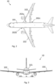
- Figs. 2 and 3 show a conventional aircraft 10 as known in the prior art, illustrated in a top view ( Fig. 2 ) and a front view ( Fig. 3 ).
- the aircraft 10 is configured as a passenger or cargo aircraft.
- the conventional aircraft 10 comprises an aircraft fuselage 101, two aircraft wings 102 and a rudder/elevator at the rear end of the aircraft fuselage 101.
- a section where the two aircraft wings 102 are connected to the aircraft fuselage 101 is called an aircraft wing-aircraft fuselage intersection 202.
- the aircraft wing-aircraft fuselage intersection 202 can be specified to an upper side 202a, a front section 202b and a rear section 202c.
- a fairing of the aircraft wing-aircraft fuselage intersection 202 for the conventional aircraft 10 covers substantially the mechanical connection between the aircraft fuselage 101 and the aircraft wings 102.
- the fairing is relatively small and kept to a minimum size.
- Figs. 4 and 5 show a schematic illustration of an aircraft 100 according to an embodiment of the invention comprising an aircraft tank device 200 according to a further embodiment of the invention. Specifically, Fig. 4 illustrates a top view and Fig. 5 a front view of the aircraft 100.
- the aircraft 100 of Figs. 4 and 5 substantially differs from the conventional aircraft 10 of Figs. 2 and 3 in that the aircraft 100 comprises an aircraft tank device 200.
- the aircraft 100 comprises an aircraft fuselage 101 and two aircraft wings 102, wherein the aircraft tank device 200 is configured as a conformal fuel tank fitted to an outer skin of the aircraft fuselage 101 and of the aircraft wings 102.
- the conformal fuel tank 200 comprises a fairing 201 which is formed and configured to partly cover the aircraft wing-aircraft fuselage intersection 202 and to store a fuel.
- the fairing 201 is formed and configured to provide a lifting function. The lifting function can be provided by an increased wing area, as it is exemplarily illustrated in Fig. 4 .
- the fairing 201 is configured as a belly fairing.
- the belly fairing 201 also called ventral fairing, is located on a bottom side of the aircraft fuselage 101 between the two aircraft wings 102.
- the fairing 201 has a trapezoidal shape.
- the fairing 201 is configured to be replaceable such that a size and/or form of the fairing 201 can be chosen depending on a flight distance.
- the replaceable fairing 201 can be changed to a small fairing for short range flights or a larger fairing for long range flights.
- the conformal fuel tank 200 can contain up to about 40 m 3 , in particular up to about 55 m 3 , fuel in addition to the fuel mainly stored in a second fuel tank which is integrated in the two aircraft wings 102.
- the stored fuel is distributed inside the fairing 201 such that a mass center of the conformal fuel tank 200 substantially corresponds to a mass center of the aircraft 100.
- the fairing 201 covers an upper side 202a and sectionwise a lower side of the aircraft wing-aircraft fuselage intersection 202. Furthermore, the fairing 201 covers a front section 202b and a rear section 202c of the aircraft wing-aircraft fuselage intersection 202.
- Fig. 6 shows a cut view of a schematic illustration of an aircraft 100 according to a further embodiment of the invention comprising an aircraft tank device 200 according to a further embodiment of the invention.
- the exemplary aircraft tank device 200 comprises a pilot valve 204, a vent pressure valve 205, a vent box 206, a plurality of hinges 207 and a fuel and air quick disconnecting element 208.
- the pilot valve 204, the vent pressure valve 205 and the vent box 206 are positioned inside the fairing 201, for example.
- the pilot valve 204, the vent pressure valve 205, the vent box 206 and the fuel and air quick disconnecting element 208 are connected via a standard fueling and transfer line 103 of the aircraft 100.
- the standard fueling and transfer line 103 is further connected to a refueling and transfer shutoff valve 104 of the aircraft 100.
- the fuel and air quick disconnecting element 208 can have an integrated refueling and transfer shutoff valve. With the fuel and air quick disconnecting element 208 and the refueling and transfer shutoff valve, respectively, the aircraft tank device 200 can be mounted and dismounted quicker and easier. Furthermore, unused fuel left in the aircraft tank device 200 can be kept in the aircraft tank device safely during mounting/dismounting and handling processes.
- the standard fueling and transfer line 103 specifically fluidly connects the refueling and transfer shutoff valve 104 with the fuel and air quick disconnecting element 208, further the fuel and air quick disconnecting element 208 with the pilot valve 204, in particular the fuel high level pilot valve 204 and the fuel low level pilot valve 204, respectively.
- the vent pressure valve 205 is fluidly connected with the fuel low level pilot valve 204
- the vent box 206 is fluidly connected with the fuel high level pilot valve 204.
- the vent pressure valve 205 allows evacuation of the overpressure or vacuum produced in an atmospheric tank during filling and emptying, or the pressure variations generated by changes in temperature, atmospheric pressure or by the variation in temperature of the fluid or the tank like failure in heating, tracing or heat exchangers.
- the plurality of hinges 207 is configured for attaching the fairing 201 to the aircraft fuselage 101 and the two aircraft wings 102. Two of the plurality of hinges 207 attach the fairing 201 to the lower side of the aircraft wing 102, and another two of the plurality of hinges 207 attach the fairing 201 to the upper side of the aircraft wing 102, for example. Another two hinges 207 attach the fairing 201 to the aircraft fuselage 101 above the aircraft wing 102, wherein a further hinge 207 attaches the fairing 201 to the aircraft fuselage 101 below the aircraft wing 102, for example. A position of the hinges 207 may correspond to a position of similar hinges of conventional fairings such that the aircraft tank device 200 can be used and interchanged with other modules of an aircraft 100.
- Fig. 7 shows a cut view of a schematic illustration of an aircraft 100 according to a further embodiment of the invention comprising an aircraft tank device 200 having a pressurized container 203 according to a further embodiment of the invention. Specifically, the cut view is illustrated at a front section 202b, that means in front of the aircraft wing 102.
- the aircraft tank device 100 substantially comprises the same features as the aircraft tank device of Fig. 1 , 4 , 5 or 6 , wherein the aircraft tank device 100 of Fig. 7 further comprises a pressurized container 203 partly or completely enclosed by the fairing 201.
- the pressurized container 203 is configured to contain a cryogenic medium, in particular liquid hydrogen.
- the pressurized container 203 can be configured as a cryogenic tank.
- the fairing 201 can be hinged to the aircraft fuselage 101 by two hinges 207, for example.
- Fig. 8 shows a perspective view of a schematic illustration of an aircraft 100 with a lowered landing gear 105 according to a further embodiment of the invention comprising an aircraft tank device 200 according to a further embodiment of the invention.
- Fig. 8 illustrates a bottom perspective view of the aircraft 100.
- the aircraft tank device 200 can be configured as one of the aircraft tank devices described in Figs. 1 , 4 , 5 , 6 and 7 .
- a fairing 201 of the aircraft tank device 200 is arranged at a front section and a rear section of an aircraft wing-aircraft fuselage intersection 202. Thereby, the aircraft tank device 200 enlarges a wing area of the aircraft wings 102.
- Fig. 8 clearly shows that the landing gear 105 can work as it is known in the prior art and not disturbed by the aircraft tank device 200.
- the aircraft tank device 200 as described above in the Figs. 1 , 4 , 5 , 6 , 7 and 8 can be adapted and used for any aircraft type, like a military, a passenger or a cargo aircraft.
- the fairing 201 can be configured as any wing-to-fuselage fairing.
- the aircraft tank device 200 may comprise a trailing edge fairing for storing fuel.
Landscapes
- Engineering & Computer Science (AREA)
- Aviation & Aerospace Engineering (AREA)
- Mechanical Engineering (AREA)
- Cooling, Air Intake And Gas Exhaust, And Fuel Tank Arrangements In Propulsion Units (AREA)
- Filling Or Discharging Of Gas Storage Vessels (AREA)
Abstract
Description
- The invention relates to an aircraft tank device for increasing a flight range and a wing area of an aircraft. The invention is furthermore concerned with an aircraft containing such an aircraft tank device.
- It is very often necessary, especially on long range flights, for an aircraft to carry an additional supply of fuel to that normally required and installed in the aircraft. Such an additional fuel is generally carried in additional tanks on the outside of the aircraft, or, more particularly, for convenience and aerodynamic reasons, may be attached to the lower surface of the wing section. These tanks can be released or dropped off, thus reducing the load and drag factor on the aircraft or for safety reasons.
- The fuel of the aircraft is normally installed in the body, the main wing, and the like with the fuel tank installed therein, but the capacity of the fuel tank is limited. In the case where further fuel is required additional tanks can be placed on the outside of the aircraft. In a conventional method, the additional tank is fixed in the outer shape and attached to the aircraft at the tip of the main wing, below the main wing or under the body. Conventionally, even if the fuel is empty in the additional tank, an additional tank having the same outer shape as that in the case where the fuel is fully loaded in the additional tank is attached, the surface area thereof is large, and the resistance of the aircraft is increased.
- Those known additional fuel tanks placed on the outside of the aircraft have the problem that may deteriorate the flight performance of the aircraft.
- According to the invention, this problem is solved in each case by the subject matters of the independent claims.
- According to a first aspect of the invention, an aircraft tank device for increasing a flight range and a wing area of an aircraft is provided. The aircraft tank device comprises a fairing which is formed and configured:
- to at least partly cover an aircraft wing-aircraft fuselage intersection,
- to store a fuel and
- to provide a lifting function.
- In particular, an aircraft tank device for increasing a flight range and a wing area of a passenger or cargo aircraft is provided.
- According to a second aspect of the invention, an aircraft, in particular a passenger or cargo aircraft, comprising an aircraft tank device according to the first aspect of the invention is provided.
- A fundamental concept of the invention is to provide an additional fuel tank device to that provided in the wings of the aircraft, wherein the additional fuel tank device can be equipped for current existing aircrafts as add-on, as well as for future aircrafts. A primary function of the fairing is to provide a smooth outline and reduce drag. The fairing can be used as a cover for gaps and spaces between parts of an aircraft to reduce form drag and interference drag, and to improve appearance. Furthermore, the aircraft tank device can store about 20 m3 to 60 m3, preferably about 40 m3, additional fuel. In particular, the fairing is formed to increase a wing area for providing the lifting function.
- A particular advantage in the solution according to an aspect of the invention is that the aircraft tank device provides more fuel storage capacity without the need for a wing redesign nor the need to use the cargo capacity, which could be equipped with so-called additional center tanks, for example. Therefore, it is possible to store less fuel inside the fuselage. Moreover, fuels with a higher volume request, like hydrogen, can be stored in the aircraft, wherein the added tank volume is provided outside the standard fuselage.
- Another advantage is that in case of water landing a crash and swimming behavior of the aircraft can be optimized by the aircraft tank device according to the invention. Further, the flight range can be extended and a lift of the aircraft can be increased. By increasing the wing area the additional weight of the aircraft tank device can be compensated. Thus, the aircraft tank device comprises a lifting body design which also provides a function for on water landing.
- Further, the aircraft tank device is substantially positioned in the center of mass of the aircraft, advantageously. In particular, the landing gear function is not disturbed by the present invention.
- Advantageous embodiments and further developments emerge from the description with reference to the figures.
- According to some aspects of the invention, the fairing is connectable to an aircraft fuselage and/or an aircraft wing. The aircraft tank device can be equipped for current existing aircrafts, in particular for current existing aircraft fuselages and/or current existing aircraft wings, as add-on, as well as for future aircrafts. The aircraft tank device may configure a module that sticks into a standard aircraft fuselage. The fairing can store liquid and/or gaseous fuels, for example kerosene. Thus, a flexibility between long and short range flights can be provided.
- According to some further aspects of the invention, the fairing is configured as a belly fairing. The belly fairing, also called a ventral fairing, is located on a bottom side of the aircraft fuselage between the main aircraft wings. The belly fairing can also cover a cargo storage compartment.
- According to some further aspects of the invention, the fairing is configured to be replaceable such that a size and/or form of the fairing can be chosen depending on a flight distance. Thus, a smaller aircraft tank device can be installed at an aircraft for short range flights. A larger aircraft tank device can be installed at an aircraft for long range flights. The replaceable fairing provides a flexible module that can be chosen depending on the specific needs for each flight.
- According to some further aspects of the invention, the aircraft tank device further comprises a pressurized container at least partly enclosed by the fairing, wherein the pressurized container is configured to contain a cryogenic medium. For example, the pressurized container can be configured as a cryogenic tank. The pressurized container may contain liquid hydrogen.
- According to some further aspects of the invention, the aircraft tank device further comprises a pilot valve, a vent pressure valve and a vent box being positioned inside the fairing. The pilot valve is a small valve that controls a limited-flow control feed to a separate piloted valve. Typically, this separate valve controls a high pressure or high flow feed. Pilot valves are useful because they allow a small and easily operated feed to control a much higher pressure or higher flow feed, which would otherwise require a much larger force to operate. The vent pressure valve allows evacuation of the overpressure or vacuum produced in an atmospheric tank during filling and emptying, or the pressure variations generated by changes in temperature, atmospheric pressure or by the variation in temperature of the fluid or the tank like failure in heating, tracing or heat exchangers.
- According to some further aspects of the invention, the aircraft tank device further comprises a plurality of hinges for attaching the fairing to an aircraft fuselage and/or an aircraft wing. A position of the hinges may correspond to a position of similar hinges of conventional fairings such that the aircraft tank device can be used and interchanged with other modules of an aircraft.
- According to some further aspects of the invention, the stored fuel is distributed inside the fairing such that a mass center of the aircraft tank device substantially corresponds to a mass center of an aircraft.
- According to some further aspects of the invention, the aircraft tank device further comprises a fuel and air quick disconnecting element. Thus, the aircraft tank device can be mounted and dismounted quicker and easier. Furthermore, unused fuel left in the aircraft tank device can be kept in the aircraft tank device safely during mounting/dismounting and handling processes.
- According to some further aspects of the invention, the aircraft further comprises an aircraft fuselage and an aircraft wing, wherein the aircraft tank device is configured as a conformal fuel tank fitted to an outer skin of the aircraft fuselage and of the aircraft wing.
- According to some further aspects of the invention, the aircraft tank device is fluidly connected to a standard fueling and transfer line. The aircraft is a multi-engine passenger or cargo aircraft, for example. A fuel system of such an aircraft may comprise multiple fuel tanks which may be located in the wing, in the fuselage or both. Each tank can be equipped with an internal fuel pump and have the associated valve and plumbing to feed the engines, allow for refueling and defueling, isolate the individual tanks and, in some applications, allow for fuel dumping or for optimization of aircraft center of gravity. The standard fueling and transfer line fluidly connects the multiple tanks, the aircraft tank device and the engine of the aircraft.
- According to some further aspects of the invention, the fairing covers at least an upper side of the aircraft wing-aircraft fuselage intersection. Furthermore, the fairing may cover a lower side of the aircraft wing-aircraft fuselage intersection sectionwise, in particular in a front section and/or a rear section of the aircraft wing-aircraft fuselage intersection.
- Optionally, the outer skin of the aircraft tank device can have an area for affixing advertisement.
- The present invention is explained more specifically below on the basis of the exemplary embodiments indicated in the schematic figures, in which:
- Fig. 1
- shows a schematic illustration of an aircraft tank device for increasing a flight range and a wing area of an aircraft according to an embodiment of the invention;
- Fig. 2
- shows a top view of a conventional aircraft as known in the prior art;
- Fig. 3
- shows a front view of the conventional aircraft according to
Fig. 2 ; - Fig. 4
- shows a top view of a schematic illustration of an aircraft according to an embodiment of the invention comprising an aircraft tank device according to a further embodiment of the invention;
- Fig. 5
- shows a front view of the aircraft according to
Fig. 4 ; - Fig. 6
- shows a cut view of a schematic illustration of an aircraft according to a further embodiment of the invention comprising an aircraft tank device according to a further embodiment of the invention;
- Fig. 7
- shows a cut view of a schematic illustration of an aircraft according to a further embodiment of the invention comprising an aircraft tank device having a pressurized container according to a further embodiment of the invention;
- Fig. 8
- shows a perspective view of a schematic illustration of an aircraft with a lowered landing gear according to a further embodiment of the invention comprising an aircraft tank device according to a further embodiment of the invention.
- The accompanying figures are intended to convey a further understanding of the embodiments of the invention. They illustrate embodiments and are used in conjunction with the description to explain principles and concepts of the invention. Other embodiments and many of the cited advantages emerge in light of the drawings. The elements of the drawings are not necessarily shown to scale in relation to one another. Direction-indicating terminology such as for example "at the top", "at the bottom", "on the left", "on the right", "above", "below", "horizontally", "vertically", "at the front", "at the rear" and similar statements are merely used for explanatory purposes and do not serve to restrict the generality to specific configurations as shown in the figures.
- In the figures of the drawing, elements, features and components that are the same, have the same function and have the same effect are each provided with the same reference signs - unless explained otherwise.
-
Fig. 1 shows a schematic illustration of anaircraft tank device 200 for increasing a flight range and a wing area of an aircraft according to an embodiment of the invention. - The
aircraft tank device 200 comprises a fairing 201 which is formed and configured to at least partly cover an aircraft wing-aircraft fuselage intersection 202 and to store a fuel. The fairing 201 can store about 30 m3 to about 50 m3, in particular about 40 m3, fuel. - Further, the fairing 201 is formed and configured to provide a lifting function. The lifting function can be provided by an increased wing area. The fairing 201 is connectable to an
aircraft fuselage 101 and anaircraft wing 102. Therefore, the fairing 201 may comprise an optimized aerodynamic form. Theaircraft tank device 200 further comprises at least twohinges 207 for attaching the fairing 201 to theaircraft wing 102. Theaircraft tank device 200 may further comprise a plurality ofhinges 207 for attaching the fairing 201 to theaircraft fuselage 101. A position of thehinges 207 may correspond to a position of similar hinges of conventional fairings such that theaircraft tank device 200 can be used and interchanged with other modules of an aircraft. -
Figs. 2 and 3 show aconventional aircraft 10 as known in the prior art, illustrated in a top view (Fig. 2 ) and a front view (Fig. 3 ). Theaircraft 10 is configured as a passenger or cargo aircraft. - The
conventional aircraft 10 comprises anaircraft fuselage 101, twoaircraft wings 102 and a rudder/elevator at the rear end of theaircraft fuselage 101. A section where the twoaircraft wings 102 are connected to theaircraft fuselage 101 is called an aircraft wing-aircraft fuselage intersection 202. The aircraft wing-aircraft fuselage intersection 202 can be specified to anupper side 202a, afront section 202b and arear section 202c. - A fairing of the aircraft wing-
aircraft fuselage intersection 202 for theconventional aircraft 10 covers substantially the mechanical connection between theaircraft fuselage 101 and theaircraft wings 102. Thus, the fairing is relatively small and kept to a minimum size. -
Figs. 4 and 5 show a schematic illustration of anaircraft 100 according to an embodiment of the invention comprising anaircraft tank device 200 according to a further embodiment of the invention. Specifically,Fig. 4 illustrates a top view andFig. 5 a front view of theaircraft 100. - The
aircraft 100 ofFigs. 4 and 5 substantially differs from theconventional aircraft 10 ofFigs. 2 and 3 in that theaircraft 100 comprises anaircraft tank device 200. - In particular, the
aircraft 100 comprises anaircraft fuselage 101 and twoaircraft wings 102, wherein theaircraft tank device 200 is configured as a conformal fuel tank fitted to an outer skin of theaircraft fuselage 101 and of theaircraft wings 102. Theconformal fuel tank 200 comprises a fairing 201 which is formed and configured to partly cover the aircraft wing-aircraft fuselage intersection 202 and to store a fuel. Further, the fairing 201 is formed and configured to provide a lifting function. The lifting function can be provided by an increased wing area, as it is exemplarily illustrated inFig. 4 . Here, the fairing 201 is configured as a belly fairing. Thebelly fairing 201, also called ventral fairing, is located on a bottom side of theaircraft fuselage 101 between the twoaircraft wings 102. For example, the fairing 201 has a trapezoidal shape. - Further, the fairing 201 is configured to be replaceable such that a size and/or form of the fairing 201 can be chosen depending on a flight distance. Thus, the
replaceable fairing 201 can be changed to a small fairing for short range flights or a larger fairing for long range flights. For example, theconformal fuel tank 200 can contain up to about 40 m3, in particular up to about 55 m3, fuel in addition to the fuel mainly stored in a second fuel tank which is integrated in the twoaircraft wings 102. The stored fuel is distributed inside the fairing 201 such that a mass center of theconformal fuel tank 200 substantially corresponds to a mass center of theaircraft 100. - In
Fig. 5 it is illustrated that the fairing 201 covers anupper side 202a and sectionwise a lower side of the aircraft wing-aircraft fuselage intersection 202. Furthermore, the fairing 201 covers afront section 202b and arear section 202c of the aircraft wing-aircraft fuselage intersection 202. -
Fig. 6 shows a cut view of a schematic illustration of anaircraft 100 according to a further embodiment of the invention comprising anaircraft tank device 200 according to a further embodiment of the invention. - The exemplary
aircraft tank device 200 comprises apilot valve 204, avent pressure valve 205, avent box 206, a plurality ofhinges 207 and a fuel and airquick disconnecting element 208. - The
pilot valve 204, thevent pressure valve 205 and thevent box 206 are positioned inside the fairing 201, for example. Thepilot valve 204, thevent pressure valve 205, thevent box 206 and the fuel and airquick disconnecting element 208 are connected via a standard fueling andtransfer line 103 of theaircraft 100. The standard fueling andtransfer line 103 is further connected to a refueling and transfershutoff valve 104 of theaircraft 100. Additionally, the fuel and airquick disconnecting element 208 can have an integrated refueling and transfer shutoff valve. With the fuel and airquick disconnecting element 208 and the refueling and transfer shutoff valve, respectively, theaircraft tank device 200 can be mounted and dismounted quicker and easier. Furthermore, unused fuel left in theaircraft tank device 200 can be kept in the aircraft tank device safely during mounting/dismounting and handling processes. - The standard fueling and
transfer line 103 specifically fluidly connects the refueling and transfershutoff valve 104 with the fuel and airquick disconnecting element 208, further the fuel and airquick disconnecting element 208 with thepilot valve 204, in particular the fuel highlevel pilot valve 204 and the fuel lowlevel pilot valve 204, respectively. Thevent pressure valve 205 is fluidly connected with the fuel lowlevel pilot valve 204, and thevent box 206 is fluidly connected with the fuel highlevel pilot valve 204. - The
vent pressure valve 205 allows evacuation of the overpressure or vacuum produced in an atmospheric tank during filling and emptying, or the pressure variations generated by changes in temperature, atmospheric pressure or by the variation in temperature of the fluid or the tank like failure in heating, tracing or heat exchangers. - The plurality of
hinges 207 is configured for attaching the fairing 201 to theaircraft fuselage 101 and the twoaircraft wings 102. Two of the plurality ofhinges 207 attach the fairing 201 to the lower side of theaircraft wing 102, and another two of the plurality ofhinges 207 attach the fairing 201 to the upper side of theaircraft wing 102, for example. Another two hinges 207 attach the fairing 201 to theaircraft fuselage 101 above theaircraft wing 102, wherein afurther hinge 207 attaches the fairing 201 to theaircraft fuselage 101 below theaircraft wing 102, for example. A position of thehinges 207 may correspond to a position of similar hinges of conventional fairings such that theaircraft tank device 200 can be used and interchanged with other modules of anaircraft 100. -
Fig. 7 shows a cut view of a schematic illustration of anaircraft 100 according to a further embodiment of the invention comprising anaircraft tank device 200 having apressurized container 203 according to a further embodiment of the invention. Specifically, the cut view is illustrated at afront section 202b, that means in front of theaircraft wing 102. - The
aircraft tank device 100 substantially comprises the same features as the aircraft tank device ofFig. 1 ,4 ,5 or6 , wherein theaircraft tank device 100 ofFig. 7 further comprises apressurized container 203 partly or completely enclosed by thefairing 201. Thepressurized container 203 is configured to contain a cryogenic medium, in particular liquid hydrogen. For example, thepressurized container 203 can be configured as a cryogenic tank. - At the
front section 202b the fairing 201 can be hinged to theaircraft fuselage 101 by twohinges 207, for example. -
Fig. 8 shows a perspective view of a schematic illustration of anaircraft 100 with a lowered landing gear 105 according to a further embodiment of the invention comprising anaircraft tank device 200 according to a further embodiment of the invention. In particular,Fig. 8 illustrates a bottom perspective view of theaircraft 100. - The
aircraft tank device 200 can be configured as one of the aircraft tank devices described inFigs. 1 ,4 ,5 ,6 and7 . A fairing 201 of theaircraft tank device 200 is arranged at a front section and a rear section of an aircraft wing-aircraft fuselage intersection 202. Thereby, theaircraft tank device 200 enlarges a wing area of theaircraft wings 102.Fig. 8 clearly shows that the landing gear 105 can work as it is known in the prior art and not disturbed by theaircraft tank device 200. - The
aircraft tank device 200 as described above in theFigs. 1 ,4 ,5 ,6 ,7 and8 can be adapted and used for any aircraft type, like a military, a passenger or a cargo aircraft. The fairing 201 can be configured as any wing-to-fuselage fairing. Alternatively or additionally, theaircraft tank device 200 may comprise a trailing edge fairing for storing fuel. - In the detailed description above, various features have been combined in one or more examples in order to improve the rigorousness of the illustration. However, it should be clear in this case that the above description is of merely illustrative but in no way restrictive nature. It serves to cover all alternatives, modifications and equivalents of the various features and exemplary embodiments. Many other examples will be immediately and directly clear to a person skilled in the art on the basis of his knowledge in the art in consideration of the above description.
- The exemplary embodiments have been chosen and described in order to be able to present the principles underlying the invention and their application possibilities in practice in the best possible way. As a result, those skilled in the art can optimally modify and utilize the invention and its various exemplary embodiments with regard to the intended purpose of use. In the claims and the description, the terms "including" and "having" are used as neutral linguistic concepts for the corresponding terms "comprising". Furthermore, use of the terms "a", "an" and "one" shall not in principle exclude the plurality of features and components described in this way.
- While at least one exemplary embodiment of the present invention(s) is disclosed herein, it should be understood that modifications, substitutions and alternatives may be apparent to one of ordinary skill in the art and can be made without departing from the scope of this disclosure. This disclosure is intended to cover any adaptations or variations of the exemplary embodiment(s). In addition, in this disclosure, the terms "comprise" or "comprising" do not exclude other elements or steps, the terms "a" or "one" do not exclude a plural number, and the term "or" means either or both. Furthermore, characteristics or steps which have been described may also be used in combination with other characteristics or steps and in any order unless the disclosure or context suggests otherwise. This disclosure hereby incorporates by reference the complete disclosure of any patent or application from which it claims benefit or priority.
-
- 100
- aircraft
- 101
- aircraft fuselage
- 102
- aircraft wing
- 103
- fueling and transfer line
- 104
- refueling and transfer shutoff valve
- 105
- landing gear
- 200
- aircraft tank device
- 201
- fairing
- 202
- aircraft wing-aircraft fuselage intersection
- 202a
- upper side
- 202b
- front section
- 202c
- rear section
- 203
- pressurized container
- 204
- pilot valve
- 205
- vent pressure valve
- 206
- vent box
- 207
- plurality of hinges
- 208
- fuel and air quick disconnecting element
Claims (13)
- Aircraft tank device (200) for increasing a flight range and a wing area of an aircraft (100), in particular of a passenger or cargo aircraft, the aircraft tank device (200) comprising a fairing (201) which is formed and configured:- to at least partly cover an aircraft wing-aircraft fuselage intersection (202),- to store a fuel and- to provide a lifting function.
- Aircraft tank device (200) according to claim 1, wherein the fairing (201) is connectable to an aircraft fuselage (101) and/or an aircraft wing (102).
- Aircraft tank device (200) according to claim 1 or 2, wherein the fairing (201) is configured as a belly fairing.
- Aircraft tank device (200) according to one of the preceding claims, wherein the fairing (201) is configured to be replaceable such that a size and/or form of the fairing (201) can be chosen depending on a flight distance.
- Aircraft tank device (200) according to one of the preceding claims, further comprising a pressurized container (203) at least partly enclosed by the fairing (201), wherein the pressurized container (203) is configured to contain a cryogenic medium.
- Aircraft tank device (200) according to one of the preceding claims, further comprising a pilot valve (204), a vent pressure valve (205) and a vent box (206) being positioned inside the fairing (201).
- Aircraft tank device (200) according to one of the preceding claims, further comprising a plurality of hinges (207) for attaching the fairing (201) to an aircraft fuselage (101) and/or an aircraft wing (102).
- Aircraft tank device (200) according to one of the preceding claims, wherein the stored fuel is distributed inside the fairing (201) such that a mass center of the aircraft tank device (200) substantially corresponds to a mass center of an aircraft (100).
- Aircraft tank device (200) according to one of the preceding claims, further comprising a fuel and air quick disconnecting element (208).
- Aircraft (100), in particular passenger or cargo aircraft, comprising an aircraft tank device (200) according to one of the preceding claims.
- Aircraft (100) according to claim 10, further comprising an aircraft fuselage (101) and an aircraft wing (102), wherein the aircraft tank device (200) is configured as a conformal fuel tank fitted to an outer skin of the aircraft fuselage (101) and of the aircraft wing (102).
- Aircraft (100) according to claim 10 or 11, wherein the aircraft tank device (200) is fluidly connected to a standard fueling and transfer line (103).
- Aircraft (100) according to one of the claims 10 to 12, wherein the fairing (201) covers at least an upper side (202a) of the aircraft wing-aircraft fuselage intersection (202).
Priority Applications (3)
| Application Number | Priority Date | Filing Date | Title |
|---|---|---|---|
| EP23200511.6A EP4530195B1 (en) | 2023-09-28 | 2023-09-28 | Aircraft tank device for increasing a flight range and a wing area of an aircraft as well as aircraft |
| US18/886,438 US20250108908A1 (en) | 2023-09-28 | 2024-09-16 | Aircraft tank device for increasing a flight range and a wing area of an aircraft as well as aircraft |
| CN202411339360.4A CN119705842A (en) | 2023-09-28 | 2024-09-25 | Aircraft tank device for increasing the flight distance and wing area of an aircraft, and aircraft |
Applications Claiming Priority (1)
| Application Number | Priority Date | Filing Date | Title |
|---|---|---|---|
| EP23200511.6A EP4530195B1 (en) | 2023-09-28 | 2023-09-28 | Aircraft tank device for increasing a flight range and a wing area of an aircraft as well as aircraft |
Publications (2)
| Publication Number | Publication Date |
|---|---|
| EP4530195A1 true EP4530195A1 (en) | 2025-04-02 |
| EP4530195B1 EP4530195B1 (en) | 2026-05-06 |
Family
ID=88237849
Family Applications (1)
| Application Number | Title | Priority Date | Filing Date |
|---|---|---|---|
| EP23200511.6A Active EP4530195B1 (en) | 2023-09-28 | 2023-09-28 | Aircraft tank device for increasing a flight range and a wing area of an aircraft as well as aircraft |
Country Status (3)
| Country | Link |
|---|---|
| US (1) | US20250108908A1 (en) |
| EP (1) | EP4530195B1 (en) |
| CN (1) | CN119705842A (en) |
Cited By (1)
| Publication number | Priority date | Publication date | Assignee | Title |
|---|---|---|---|---|
| CN121134020A (en) * | 2025-11-18 | 2025-12-16 | 中航通飞华南飞机工业有限公司 | A lightweight fuel transfer system and method for integrated design of seaplanes |
Citations (5)
| Publication number | Priority date | Publication date | Assignee | Title |
|---|---|---|---|---|
| CA462978A (en) * | 1950-02-07 | De Muyser Alfred | Aeroplane | |
| CN108945488A (en) * | 2017-05-23 | 2018-12-07 | 成都飞机工业(集团)有限责任公司 | A kind of Conformal Fuel Tanks |
| GB2591255A (en) * | 2020-01-22 | 2021-07-28 | Airbus Operations Ltd | An aircraft |
| FR3128196A1 (en) * | 2021-10-15 | 2023-04-21 | François GELI | Hybrid airliner that can run on hydrogen, |
| CN113753216B (en) * | 2021-09-19 | 2023-08-22 | 中国航空工业集团公司西安飞机设计研究所 | A platform configuration of shipborne UAV based on task modularization |
Family Cites Families (7)
| Publication number | Priority date | Publication date | Assignee | Title |
|---|---|---|---|---|
| US2675828A (en) * | 1948-09-18 | 1954-04-20 | United Aircraft Prod | Electromagnetic pilot controlled valve system for main and auxiliary fuel lines |
| FR2871436B1 (en) * | 2004-06-11 | 2007-09-07 | Airbus France Sas | AIRCRAFT PROVIDED WITH A VENTRAL CARENAGE AND VENTRAL CARENAGE. |
| ES2578427T3 (en) * | 2012-12-27 | 2016-07-26 | Airbus Operations S.L. | An ventral fairing of an aircraft with improved storage capacity |
| US9499268B2 (en) * | 2014-03-27 | 2016-11-22 | Northrop Grumman Systems Corporation | Near belly-tangent pod system for an aircraft |
| GB202100665D0 (en) * | 2021-01-19 | 2021-03-03 | Rolls Royce Plc | Aircraft with hydrogen storage tanks |
| US12617546B2 (en) * | 2022-05-03 | 2026-05-05 | Sas Beyond Aerospace | Modular hydrogen-fuel storage assembly |
| US12269606B2 (en) * | 2023-09-01 | 2025-04-08 | The Boeing Company | Aircraft |
-
2023
- 2023-09-28 EP EP23200511.6A patent/EP4530195B1/en active Active
-
2024
- 2024-09-16 US US18/886,438 patent/US20250108908A1/en active Pending
- 2024-09-25 CN CN202411339360.4A patent/CN119705842A/en active Pending
Patent Citations (5)
| Publication number | Priority date | Publication date | Assignee | Title |
|---|---|---|---|---|
| CA462978A (en) * | 1950-02-07 | De Muyser Alfred | Aeroplane | |
| CN108945488A (en) * | 2017-05-23 | 2018-12-07 | 成都飞机工业(集团)有限责任公司 | A kind of Conformal Fuel Tanks |
| GB2591255A (en) * | 2020-01-22 | 2021-07-28 | Airbus Operations Ltd | An aircraft |
| CN113753216B (en) * | 2021-09-19 | 2023-08-22 | 中国航空工业集团公司西安飞机设计研究所 | A platform configuration of shipborne UAV based on task modularization |
| FR3128196A1 (en) * | 2021-10-15 | 2023-04-21 | François GELI | Hybrid airliner that can run on hydrogen, |
Cited By (1)
| Publication number | Priority date | Publication date | Assignee | Title |
|---|---|---|---|---|
| CN121134020A (en) * | 2025-11-18 | 2025-12-16 | 中航通飞华南飞机工业有限公司 | A lightweight fuel transfer system and method for integrated design of seaplanes |
Also Published As
| Publication number | Publication date |
|---|---|
| CN119705842A (en) | 2025-03-28 |
| EP4530195B1 (en) | 2026-05-06 |
| US20250108908A1 (en) | 2025-04-03 |
Similar Documents
| Publication | Publication Date | Title |
|---|---|---|
| EP3524526B1 (en) | Fuselage embedded fuel tank | |
| EP2384972B1 (en) | System and Method to Provide Overpressure Proctection of an Aircraft Fuel Tank System | |
| EP2114766B1 (en) | Aircraft fuel tanks, systems and methods for increasing an aircraft's on-board fuel capacity | |
| EP2861306B1 (en) | Unmanned aircraft systems for firefighting | |
| US12208913B2 (en) | Fuselage section of an aircraft, aircraft fuselage, and aircraft | |
| JP6163041B2 (en) | Fuel system, aircraft | |
| US20060214061A1 (en) | Auxiliary fuel tank systems for aircraft and methods for their manufacture and use | |
| US20050178916A1 (en) | Auxiliary fuel tank systems for aircraft and methods for their manufacture and use | |
| EP3130540B1 (en) | Tanker aircraft capacity extension system and method | |
| US20250108908A1 (en) | Aircraft tank device for increasing a flight range and a wing area of an aircraft as well as aircraft | |
| EP1183181B1 (en) | Aircraft structure fatigue alleviation | |
| US5983945A (en) | Wing tank liner | |
| KR102702800B1 (en) | An aircraft with a fuel storage system | |
| Goraj et al. | Aircraft fuel systems and their influence on stability margin | |
| Habibullah | AUTOMATION OF AIRCRAFT FUEL DISTRIBUTION SYSTEM | |
| RU2752810C1 (en) | Multi-purpose helicopter and helicopter fuel system | |
| HK40063440A (en) | An aircraft with a fuel storage system |
Legal Events
| Date | Code | Title | Description |
|---|---|---|---|
| PUAI | Public reference made under article 153(3) epc to a published international application that has entered the european phase |
Free format text: ORIGINAL CODE: 0009012 |
|
| STAA | Information on the status of an ep patent application or granted ep patent |
Free format text: STATUS: THE APPLICATION HAS BEEN PUBLISHED |
|
| AK | Designated contracting states |
Kind code of ref document: A1 Designated state(s): AL AT BE BG CH CY CZ DE DK EE ES FI FR GB GR HR HU IE IS IT LI LT LU LV MC ME MK MT NL NO PL PT RO RS SE SI SK SM TR |
|
| STAA | Information on the status of an ep patent application or granted ep patent |
Free format text: STATUS: REQUEST FOR EXAMINATION WAS MADE |
|
| 17P | Request for examination filed |
Effective date: 20250922 |
|
| GRAP | Despatch of communication of intention to grant a patent |
Free format text: ORIGINAL CODE: EPIDOSNIGR1 |
|
| STAA | Information on the status of an ep patent application or granted ep patent |
Free format text: STATUS: GRANT OF PATENT IS INTENDED |
|
| INTG | Intention to grant announced |
Effective date: 20260119 |
|
| GRAS | Grant fee paid |
Free format text: ORIGINAL CODE: EPIDOSNIGR3 |
|
| GRAA | (expected) grant |
Free format text: ORIGINAL CODE: 0009210 |
|
| STAA | Information on the status of an ep patent application or granted ep patent |
Free format text: STATUS: THE PATENT HAS BEEN GRANTED |
|
| AK | Designated contracting states |
Kind code of ref document: B1 Designated state(s): AL AT BE BG CH CY CZ DE DK EE ES FI FR GB GR HR HU IE IS IT LI LT LU LV MC ME MK MT NL NO PL PT RO RS SE SI SK SM TR |
|
| REG | Reference to a national code |
Ref country code: CH Ref legal event code: F10 Free format text: ST27 STATUS EVENT CODE: U-0-0-F10-F00 (AS PROVIDED BY THE NATIONAL OFFICE) Effective date: 20260506 Ref country code: GB Ref legal event code: FG4D |