EP4530190A1 - Ice protection system having memory-based ice removal elements - Google Patents
Ice protection system having memory-based ice removal elements Download PDFInfo
- Publication number
- EP4530190A1 EP4530190A1 EP24200786.2A EP24200786A EP4530190A1 EP 4530190 A1 EP4530190 A1 EP 4530190A1 EP 24200786 A EP24200786 A EP 24200786A EP 4530190 A1 EP4530190 A1 EP 4530190A1
- Authority
- EP
- European Patent Office
- Prior art keywords
- shape
- removal element
- ice
- memory characteristics
- memory
- Prior art date
- Legal status (The legal status is an assumption and is not a legal conclusion. Google has not performed a legal analysis and makes no representation as to the accuracy of the status listed.)
- Pending
Links
Images





Classifications
-
- B—PERFORMING OPERATIONS; TRANSPORTING
- B64—AIRCRAFT; AVIATION; COSMONAUTICS
- B64D—EQUIPMENT FOR FITTING IN OR TO AIRCRAFT; FLIGHT SUITS; PARACHUTES; ARRANGEMENT OR MOUNTING OF POWER PLANTS OR PROPULSION TRANSMISSIONS IN AIRCRAFT
- B64D15/00—De-icing or preventing icing on exterior surfaces of aircraft
- B64D15/12—De-icing or preventing icing on exterior surfaces of aircraft by electric heating
-
- B—PERFORMING OPERATIONS; TRANSPORTING
- B64—AIRCRAFT; AVIATION; COSMONAUTICS
- B64D—EQUIPMENT FOR FITTING IN OR TO AIRCRAFT; FLIGHT SUITS; PARACHUTES; ARRANGEMENT OR MOUNTING OF POWER PLANTS OR PROPULSION TRANSMISSIONS IN AIRCRAFT
- B64D15/00—De-icing or preventing icing on exterior surfaces of aircraft
- B64D15/16—De-icing or preventing icing on exterior surfaces of aircraft by mechanical means, e.g. pulsating mats or shoes attached to, or built into, surface
-
- B—PERFORMING OPERATIONS; TRANSPORTING
- B29—WORKING OF PLASTICS; WORKING OF SUBSTANCES IN A PLASTIC STATE IN GENERAL
- B29C—SHAPING OR JOINING OF PLASTICS; SHAPING OF MATERIAL IN A PLASTIC STATE, NOT OTHERWISE PROVIDED FOR; AFTER-TREATMENT OF THE SHAPED PRODUCTS, e.g. REPAIRING
- B29C61/00—Shaping by liberation of internal stresses; Making preforms having internal stresses; Apparatus therefor
- B29C61/06—Making preforms having internal stresses, e.g. plastic memory
- B29C61/0608—Making preforms having internal stresses, e.g. plastic memory characterised by the configuration or structure of the preforms
- B29C61/0625—Preforms comprising incorporated or associated heating means
-
- B—PERFORMING OPERATIONS; TRANSPORTING
- B29—WORKING OF PLASTICS; WORKING OF SUBSTANCES IN A PLASTIC STATE IN GENERAL
- B29L—INDEXING SCHEME ASSOCIATED WITH SUBCLASS B29C, RELATING TO PARTICULAR ARTICLES
- B29L2031/00—Other particular articles
- B29L2031/30—Vehicles, e.g. ships or aircraft, or body parts thereof
- B29L2031/3076—Aircrafts
-
- B—PERFORMING OPERATIONS; TRANSPORTING
- B29—WORKING OF PLASTICS; WORKING OF SUBSTANCES IN A PLASTIC STATE IN GENERAL
- B29L—INDEXING SCHEME ASSOCIATED WITH SUBCLASS B29C, RELATING TO PARTICULAR ARTICLES
- B29L2031/00—Other particular articles
- B29L2031/772—Articles characterised by their shape and not otherwise provided for
Definitions
- the present disclosure relates to ice protection systems (IPSs) and, more particularly, to a novel IPS having memory-based ice removal elements.
- IPSs ice protection systems
- Aircraft and engine ice protection systems are generally designed to prevent ice from forming or remove the ice after it has formed.
- the latter type of system is referred to as a de-icing system, and the former is referred to as an anti-icing system.
- De-icing and anti-icing systems can be referred to generally as ice protection systems (IPS).
- IPS ice protection systems
- Various modes of IPS include pneumatic, electro-thermal and electro-mechanical expulsion systems.
- a common feature of known IPS is the application of some type of external influence to dislodge ice that has formed on the aircraft.
- pneumatic systems mechanical stress applied by inflatable rubber bladders can be used to remove ice.
- the pneumatic system is initiated by activating an actuator that expands the inflatable rubber bladders such that, when they expand, ice is sheared, cracked and flaked off.
- the actuator can be installed as a thin cap (a boot) that covers the ice prone area.
- a protection system including a removal element having shape-memory characteristics.
- the shape-memory characteristics have been configured to define a first shape of the removal element and a second shape of the removal element.
- TBP to-be-protected
- the removal element is in a first position with respect to a to-be-protected (TBP) region of a structure.
- TBP to-be-protected
- the removal element is in a second position with respect to the TBP region of the structure.
- the removal element is responsive to an activation that prompts the removal element to, under influence of the shape-memory characteristics, take on the second shape.
- the removal element is responsive to an inactivation that prompts the removal element to, under influence of the shape-memory characteristics, take on the first shape.
- the shape-memory characteristics include an electroactive shape-memory effect; and the influence of the shape-memory characteristics includes influence of the electroactive shape-memory effect.
- the removal element includes conductive nanowires.
- the removal element further includes a polymer.
- the removal element taking on the second shape ruptures ice formed on the removal element.
- the removal element taking on the first shape assists with protecting the TBP region of the structure from the ice.
- the activation generates heat within the removal element.
- the heat passes through the removal element to the ice.
- the activation is generated by a controller responsive a determination that the ice is formed on the removal element.
- a protection system including a controller electronically coupled to a removal element having shape-memory characteristics.
- the shape-memory characteristics have been configured to define a first shape of the removal element and a second shape of the removal element.
- the removal element is in the first shape, the removal element is in a first position with respect to a TBP region of a structure.
- the removal element is in the second shape, the removal element is in a second position with respect to the TBP region of the structure.
- the controller generates an activation that prompts the removal element to, under influence of the shape-memory characteristics, take on the second shape.
- the controller further generates an inactivation that prompts the removal element to, under influence of the shape-memory characteristics, take on the first shape.
- the shape-memory characteristics include an electroactive shape-memory effect; and the influence of the shape-memory characteristics includes influence of the electroactive shape-memory effect.
- the removal element includes conductive nanowires and a polymer.
- the removal element taking on the second shape ruptures ice formed on the removal element; the removal element taking on the first shape assists with protecting the TBP region of the structure from the ice; the activation generates heat that passes through the removal element to the ice; and the controller generates the activation responsive a determination that the ice is formed on the removal element.
- the fabrication operations include providing a removal element having shape-memory characteristics.
- the fabrication operations further include configuring the shape-memory characteristics to define a first shape of the removal element and a second shape of the removal element.
- the removal element is in the first shape, the removal element is in a first position with respect to a TBP region of a structure.
- the removal element is in the second shape, the removal element is in a second position with respect to the TBP region of the structure.
- the fabrication operations further include configuring the removal element to be responsive to an activation that prompts the removal element to, under influence of the shape-memory characteristics, take on the second shape.
- the fabrication operations further include configuring the removal element to be responsive to an inactivation that prompts the removal element to, under influence of the shape-memory characteristics, take on the first shape.
- the shape-memory characteristics include an electroactive shape-memory effect; and the influence of the shape-memory characteristics includes influence of the electroactive shape-memory effect.
- the removal element includes conductive nanowires and a polymer.
- the removal element taking on the second shape ruptures ice formed on the removal element; the removal element taking on the first shape assists with protecting the TBP region of the structure from the ice; the activation generates heat that passes through the removal element to the ice; and the activation is generated by a controller responsive a determination that the ice is formed on the removal element.
- Ice on an aircraft during flight has a variety of negative impacts, including decreased lift, increased weight, decreased thrust, and increased drag.
- aircraft and engine ice protection systems are generally designed to prevent ice from forming or remove the ice after it has formed.
- the latter type of system is referred to as a de-icing system, and the former is referred to as an anti-icing system.
- De-icing and anti-icing systems can be referred to generally as ice protection systems (IPS).
- IPS ice protection systems
- Various modes of IPS include pneumatic, electro-thermal and electro-mechanical expulsion systems.
- a common feature of known IPS is the application of some type of external influence to dislodge ice that has formed on the aircraft.
- pneumatic systems mechanical stress applied by inflatable rubber bladders can be used to remove ice.
- the pneumatic system is initiated by activating an actuator that expands the inflatable rubber bladders such that, when they expand, ice is sheared, cracked and flaked off.
- the actuator can be installed as a thin cap (a boot) that covers the ice prone area. Rubber pneumatic caps/boots are prone to damage from weather and foreign objects. Further, they cannot remove thin layers of ice.
- Exemplary embodiments of the disclosure provide a novel IPS having a memory-based ice removal element operable to include shape-memory characteristics.
- the shape-memory characteristics are configured to define a first shape of the removal element and a second shape of the removal element.
- TBP to-be-protected
- the removal element is in a first position with respect to a to-be-protected (TBP) region of a structure (e.g., an aircraft wing).
- TBP to-be-protected
- the removal element is responsive to an activation that prompts the removal element to, under influence of the shape-memory characteristics, take on the second shape.
- the removal element is also responsive to an inactivation that prompts the removal element to, under influence of the shape-memory characteristics, take on the first shape.
- the removal element includes conductive nanowires and a polymer.
- the removal element taking on the second shape ruptures ice formed on the removal element, and the removal element taking on the first shape assists with protecting the TBP region of the structure from the ice.
- the activation generates heat that passes through the removal element to the melt the ice and assist with rupturing the ice.
- the activation can be generated by a controller responsive a determination that the ice is formed on the removal element.
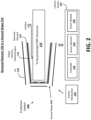
- FIG. 1 and FIG. 2 are simplified block diagrams illustrating a protection system 100 in accordance with embodiments of the disclosure. More specifically, FIG. 1 illustrates a removal element 120 of the system 100 while the removal element 120 is in a first shape 124; and FIG. 2 illustrates the removal element 120 of the system 100 while the removal element 120 is in a second shape 224.
- the protection system 100 includes the removal element 120 electronically coupled to a control system 140 and electronically and/or mechanically coupled to an anchor mechanism 150.
- the control system 140 includes a controller 142, a sensor network 144 and a power module 146, configured and arranged as shown.
- the controller 142 applies various control and/or shape-formation signals to the removal element 120; the sensor network 144 senses various parameter (e.g., formation and thickness of the ice 130) related to the shape-formation and operation of the removal element 120 and provides the same to the controller 142; and the power module 146 provides all of the power requirements of the protection system 100.
- the removal element 120 includes shape-memory characteristics 122 and is formed over a surface 112 (best shown in FIG. 2 ) of a to-be-protected (TBP) structure 110. As best shown in FIG. 1 , a layer of ice 130 has formed on the removal element 120 while the removal element 120 has the first shape 124.
- the removal element 120 When the removal element 120 takes on the first shape 124, the removal element 120 is in a first position with respect to the TBP structure 110 and the surface 112 such that the removal element 120 prevents the ice 130 from forming on the surface 112.
- the removal element 120 When the removal element 120 takes on the second shape 224, the removal element 120 is in a second position with respect to the TBP structure 110 and the surface 112 (or TBP surface 112) such that the removal element 120 ruptures and substantially removes the ice 130 that formed on the removal element 120.
- the anchor mechanism 150 is any suitable electronically-controlled and/or electro-mechanically controlled mechanism that secures the removal element 120 so that it does not completely fall away from the TBP structure 110 as the removal element 110 moves back and forth between the first shape 124 and the second shape 224 (shown in FIG. 2 ).
- the shapes, positions, and sizes of the TBP structure 110, the removal element 120, the first shape 124, the second shape 224 and the ice 130 in FIGS. 1 and 2 are for ease of illustration and description.
- various shapes, positions, and sizes of the TBP structure 110, the removal element 120, the first shape 124, the second shape 224 and the ice 130 can be provided.
- the removal element 120 can include a protective housing (now shown separately from the removal element 120) that protects the main functional components (e.g., the polymer and the conductive nanowires) of the removal element 120 from harsh environmental elements that can impact (e.g., where the TBP structure 110 is an aircraft wing).
- the components of the control system 140 are depicted in the Figures as separate components for ease of illustration and explanation.
- the components of the control system 140 can be integrated with one another in any suitable combination.
- the controller 142 and the power module 146 can be integrated into one component.
- some operations of the controller 142 can be distributed to local processor functionality provided in the sensor network 144 (e.g., forming a smart sensor or an IoT device) and/or the power module 146 (e.g., forming a smart power module).
- the shape-memory characteristics 122 of the removal element 120 are used to set the first shape 124 of the removal element 120 and further set the second shape 224 (shown in FIG. 2 ) of the removal element 120.
- the removal element 120 can include a flexible polymer having a network of conductive nanowires embedded therein; and the flexible polymer and the conductive nanowires, operating under the influence a current applied to the removal element 120 (e.g., through the network of nanowires), provide some or all of the shape-memory characteristics 122 of the removal element 120.
- the second shape 224 can be set by fabricating the removal element 120 in the desired second shape 224.
- the first shape 124 can be set by placing and holding the removal element 120 in the first shape 124 and applying a current (e.g., using the controller 142 and the power module 146) for a duration of time.
- a current e.g., using the controller 142 and the power module 146
- the removal element 120 will, in effect, "remember” or "recover” its original shape, which is the second shape 224.
- the shape-memory characteristics 122 that enable the removal element 120 to, in effect, "remember” or “recover” its original shape leverage the electroactive shape-memory effect built into the removal element 120 during fabrication thereof.
- Non-limiting examples of how the removal element 120 can be fabricated in accordance with aspects of the disclosure are depicted in FIGS. 7 and 8 and described in greater detail subsequently herein.
- the activation when implemented as a current through the network of conductive nanowires of the removal element 120, in sufficient cause some or all of the conductive nanowires to exhibit Joule heating in response to applied current.
- the generated heat can pass through the flexible polymer portion of the removal element 120 to the ice 130 to initiate a process of melting the ice 130 concurrently with the removal element 120 taking on the second shape 224.
- Non-limiting examples of how the first shape 124 and the second shape 224 can be set for some embodiments of the removal element 120 are depicted in FIG. 3-6 and described in greater detail subsequently herein.
- the removal element 120 having shape-memory characteristics 122 in accordance with aspects of the disclosure absorbs less stress and experiences fewer failures than known pneumatic boot-activated rubber bladders because the removal element 120 does not change position/shape under the influence of an external mechanical force but instead changes position under the influence of its own internal structure, which imparts very little stress to the removal element 120.
- the construction and operation of the removal element 120 significantly reduces the likelihood of the removal element 120 experiencing common failures such as ruptures; cracking (cold cracking); balloon/burst; stitch failure; abrasion/cuts/tears; failure to inflate/deflate; air connection failure; and ice bridging, all of which are observed in pneumatic boot-activated rubber bladders used in known IPSs.
- FIG. 3 is a flow diagram illustrating a methodology 300 in accordance with embodiments of the disclosure.
- the TBP structure 110 is implemented as an aircraft wing 110A
- the removal element 120 is implemented as a shape-memory polymer composite (SMPC) laminate structure, referenced herein as SMPC 120A.
- Stage 1 depicts an inactive or shape fixing condition of the SMPC 120A.
- the SMPC 120A Prior to shape fixing, the SMPC 120A has been fabricated to have an initial or original shape, and this initial/original shape corresponds the second shape 224 shown in FIG. 2 .
- SMPC shape-memory polymer composite
- the controller 142 working in tandem with the power module 146 applies a voltage (e.g., about 40V) through a conductive wire (e.g., copper) fixed at each end of the SMPC 120A to heat it to a predetermined temperature (e.g., about 70°C).
- the predetermined temperature is maintained for a predetermined duration (e.g., a few seconds) to attain uniform heat distribution.
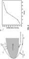
- a force is applied to the SMPC 120A to deform the SMPC 120A from its initial/original shape to structure to the angle ⁇ i (shown in FIG. 4 ) around the leading edge of the aircraft wing 110A.
- the controller 142 stops the electric supply while maintaining the force to allow the SMPC 120A to cool. Upon removing the force after cooling, a small elastic recovery can be seen, and an angle ⁇ fix (shown in FIG. 4 ) is obtained.
- Stage 2 depicts activation or shape recover operations of the SMPC 120A under control of the controller 142.
- the controller 142 applies an activation (e.g., a voltage of about 40V) to the SMPC 120A, which prompts the SMPC 120A to recover its original, as-fabricated shape.
- an activation e.g., a voltage of about 40V
- Complete shape recovery (angle ⁇ i- ⁇ f ) (shown in FIG. 4 ) can be observed within a predetermined activation time (e.g., about 60 seconds).
- heat energy from the activation voltage is released from the SMPC 120A and melts the ice 130 at the interface between ice 130 and the SMPC 120A, thereby assisting with rupturing and dislodging the ice 130 from the SMPC 120A.
- the expanded shape of the SMPC 120A ruptures and/or shreds the ice 130 and airflow blows the ice 130 off of the SMPC 120A.
- the SMPC 120A can formed using a graphite/silver nanowires/epoxy resin (known in the art by the acronym "PGSE”) composite with a volume ratio of AgNWs to graphite of about 1: 1.
- PGSE graphite/silver nanowires/epoxy resin
- the porous polymer foam works as the skeleton of the SMPC 120A by forming 3-dimensional graphite structure whereas the silver nanowires act as the continuous conductive network.
- Experimental study has shown that PGSE showed Rf and Rr values of nearly 99% and 97%, respectively.
- ⁇ fix angle obtained after elastic recovery during shape fixing
- Rr is about 97%
- the approximate resistance of PGSE both wings obtained from the conductivity is 10.4 ohms.
- Equation-3 shown in FIG. 5 as about 154 Watts.
- the graph 400 shown in FIG. 4 depicts the variation of the recovery angle of PGSE composite material with 10 wt% (weight percentage) graphite sheets and 3wt% AgNWs under a voltage of about 40 volts.
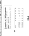
- FIG. 6 depicts a table 600 illustrating properties of PGSE composites that can be used in aspects of the invention.
- the PGSE structure's manufactured shape will be in accordance with the required angle of activation/recovery shape with respect to the surface 112 (shown in FIG. 1 ).
- Inactivation of the SMPC 120A is accomplished by deforming & fixing the SMPC 120A around the TBP structure 110 (e.g., the aircraft wing 110A).
- the controller 142 and the power module 146 Upon activation under operation of the controller 142 and the power module 146, the SMPC 120A will recover its original shape due to the electroactive shape-memory effect, causing the ice 130 to shear and blown off by airflow.
- the proposed PGSE composite has demonstrated conductivity, thermal stability and shape recovery that can be triggered within about 60 seconds by application of an about 0.8V/mm electric field. By increasing the input voltage, recovery time can be reduced to below 10 seconds.
- PGSE composites provide high and reliable electrical conductivity & thermal stability; high and reliable shape fixity and recovery ratios; high and reliable mechanical strength, and stiffness; shape recovery without an external heat source; and ease of fabrication using readily available raw materials & shape controllability.
- FIGS. 7 and 8 are flow diagrams illustrating a methodology 700, 800 for fabricating a SMPC 120A in accordance with embodiments of the disclosure.
- the methodology 700 begins by providing a thermoplastic foam 702A (e.g., a polymeric foam).
- the thermoplastic foam 702A is immersed in a mixture of highly conductive carbon nanotubes (CNTs) or graphite oxide (GO), silver nanowires (AgNWs), and vitamin C, thereby generating intermediate structure 702B.
- Step-2 an in-situ chemical reduction process is applied for GO to assemble the GO and AgNWs on foam to obtain the PGS (Poly (glycerol sebacate) ) foam structure 702C.
- Step-3 a pyrolysis process is applied to obtain the graphite/AgNWs hybrid foams structure 702D.
- Step-4 the graphite/AgNWs hybrid foams structure 702D is immersed in thermoplastic resin (e.g., epoxy resin (EP)) followed by curing to obtain the PGSE composite structure 702E.
- thermoplastic resin e.g., epoxy resin (EP)
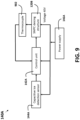
- FIG. 9 is a simplified block diagram illustrating a non-limiting example of how the control system 140 (shown in FIG. 1 ) can be implemented as a control system 140A, which includes a control unit 142A (corresponds to the controller 142), a power supply 146A (corresponds to the power module 146), a capacitive ice detection sensor 144A (corresponds to the sensor network 144), and a thermocouple element 902, configured and arranged as shown. Additionally, the SMPC deicing structure 120B corresponds to the removal element 120 and the SMPC 120A.
- the control system 140A performs all of the operations performed by the control system 140 but further uses the capacitive sensors 144A to generate sensor input upon ice formation (the ice 130 shown in FIG.
- the control unit 142A and the power suppl 146A generate the necessary activation signals and instructions to activate the SMPC deicing structure 120B.
- the thermocouple 902 can be used to sense the temperature associated with the SMPC deicing structure 120B and limit the electric supply after reaching desired temperature, thereby avoiding excessive power supply usage.
- the sensors 144A continuously detect ice formation on an associated surface and send data to the controller 142A.
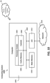
- FIG. 10 illustrates an example of a computer system 1000 that can be used to implement the computer-based components in accordance with aspects of the disclosure.
- the computer system 1000 includes an exemplary computing device ("computer") 1002 configured for performing various aspects of the content-based semantic monitoring operations described herein in accordance aspects of the disclosure.
- exemplary computer system 1000 includes network 1014, which connects computer 1002 to additional systems (not depicted) and can include one or more wide area networks (WANs) and/or local area networks (LANs) such as the Internet, intranet(s), and/or wireless communication network(s).
- WANs wide area networks
- LANs local area networks
- Computer 1002 and additional system are in communication via network 1014, e.g., to communicate data between them.
- Exemplary computer 1002 includes processor cores 1004, main memory (“memory”) 1010, and input/output component(s) 1012, which are in communication via bus 1003.
- Processor cores 1004 includes cache memory ("cache") 1006 and controls 1008, which include branch prediction structures and associated search, hit, detect and update logic, which will be described in more detail below.
- Cache 1006 can include multiple cache levels (not depicted) that are on or off-chip from processor 1004.
- Memory 1010 can include various data stored therein, e.g., instructions, software, routines, etc., which, e.g., can be transferred to/from cache 1006 by controls 1008 for execution by processor 1004.
- Input/output component(s) 1012 can include one or more components that facilitate local and/or remote input/output operations to/from computer 1002, such as a display, keyboard, modem, network adapter, etc. (not depicted).
- a cloud computing system 50 is in wired or wireless electronic communication with the computer system 1000.
- the cloud computing system 50 can supplement, support or replace some or all of the functionality (in any combination) of the computing system 1000. Additionally, some or all of the functionality of the computer system 1000 can be implemented as a node of the cloud computing system 50.
- the generation of the appropriate control signals described herein e.g., activation, inactivation, shape setting signals, and the like
- the controller 142 can be configured to include machine learning algorithms configured and arranged to perform the removal element control operations described herein as machine learning tasks.
- machine learning techniques are run on so-called "neural networks," which can be implemented as programmable computers configured to run sets of machine learning algorithms and/or natural language processing algorithms.
- Neural networks incorporate knowledge from a variety of disciplines, including neurophysiology, cognitive science/psychology, physics (statistical mechanics), control theory, computer science, artificial intelligence, statistics/mathematics, pattern recognition, computer vision, parallel processing and hardware (e.g., digital/analog/VLSI/optical).
- disciplines including neurophysiology, cognitive science/psychology, physics (statistical mechanics), control theory, computer science, artificial intelligence, statistics/mathematics, pattern recognition, computer vision, parallel processing and hardware (e.g., digital/analog/VLSI/optical).
- the basic function of neural networks and their machine learning algorithms is to recognize patterns by interpreting unstructured sensor data through a kind of machine perception.
- Unstructured real-world data in its native form e.g., from the sensor(s) 144A
- a numerical form e.g., a vector having magnitude and direction
- the machine learning algorithm performs multiple iterations of learning-based analysis on the real-world data vectors until patterns (or relationships) contained in the real-world data vectors are uncovered and learned.
- the learned patterns/relationships function as predictive models that can be used to perform a variety of tasks, including, for example, classification (or labeling) of real-world data and clustering of real-world data.
- Classification tasks often depend on the use of labeled datasets to train the neural network (i.e., the model) to recognize the correlation between labels and data. This is known as supervised learning. Examples of classification tasks include identifying objects in images (e.g., stop signs, pedestrians, lane markers, etc.), recognizing gestures in video, detecting voices, detecting voices in audio, identifying particular speakers, transcribing speech into text, and the like. Clustering tasks identify similarities between objects, which the clustering task groups according to those characteristics in common and which differentiate them from other groups of objects. These groups are known as "clusters.”
- modules can be implemented as a hardware circuit including custom VLSI circuits or gate arrays, off-the-shelf semiconductors such as logic chips, transistors, or other discrete components.
- a module can also be implemented in programmable hardware devices such as field programmable gate arrays, programmable array logic, programmable logic devices or the like.
- Modules can also be implemented in software for execution by various types of processors.
- An identified module of executable code can, for instance, include one or more physical or logical blocks of computer instructions which can, for instance, be organized as an object, procedure, or function. Nevertheless, the executables of an identified module need not be physically located together, but can include disparate instructions stored in different locations which, when joined logically together, function as the module and achieve the stated purpose for the module.
- the disclosure can be embodied as a system, a method, and/or a computer program product at any possible technical detail level of integration
- the computer program product may include a computer readable storage medium (or media) having computer readable program instructions thereon for causing a processor to carry out aspects of the present disclosure
- the computer readable storage medium can be a tangible device that can retain and store instructions for use by an instruction execution device.
- the computer readable storage medium may be, for example, but is not limited to, an electronic storage device, a magnetic storage device, an optical storage device, an electromagnetic storage device, a semiconductor storage device, or any suitable combination of the foregoing.
- a non-exhaustive list of more specific examples of the computer readable storage medium includes the following: a portable computer diskette, a hard disk, a random access memory (RAM), a read-only memory (ROM), an erasable programmable read-only memory (EPROM or Flash memory), a static random access memory (SRAM), a portable compact disc read-only memory (CD-ROM), a digital versatile disk (DVD), a memory stick, a floppy disk, a mechanically encoded device such as punch-cards or raised structures in a groove having instructions recorded thereon, and any suitable combination of the foregoing.
- RAM random access memory
- ROM read-only memory
- EPROM or Flash memory erasable programmable read-only memory
- SRAM static random access memory
- CD-ROM compact disc read-only memory
- DVD digital versatile disk
- memory stick a floppy disk
- a mechanically encoded device such as punch-cards or raised structures in a groove having instructions recorded thereon
- a computer readable storage medium is not to be construed as being transitory signals per se, such as radio waves or other freely propagating electromagnetic waves, electromagnetic waves propagating through a waveguide or other transmission media (e.g., light pulses passing through a fiber-optic cable), or electrical signals transmitted through a wire.
- Computer readable program instructions described herein can be downloaded to respective computing/processing devices from a computer readable storage medium or to an external computer or external storage device via a network, for example, the Internet, a local area network, a wide area network and/or a wireless network.
- the network may comprise copper transmission cables, optical transmission fibers, wireless transmission, routers, firewalls, switches, gateway computers and/or edge servers.
- a network adapter card or network interface in each computing/processing device receives computer readable program instructions from the network and forwards the computer readable program instructions for storage in a computer readable storage medium within the respective computing/processing device.
Landscapes
- Engineering & Computer Science (AREA)
- Aviation & Aerospace Engineering (AREA)
- Mechanical Engineering (AREA)
- Micromachines (AREA)
Abstract
A protection system including a removal element (120) having shape-memory characteristics. The shape-memory characteristics have been configured to define a first shape of the removal element (120) and a second shape of the removal element (120). When the removal element (120) is in the first shape, the removal element (120) is in a first position with respect to a to-be-protected (TBP) region of a structure. When the removal element (120) is in the second shape, the removal element (120) is in a second position with respect to the TBP region of the structure. The removal element (120) is responsive to an activation that prompts the removal element to, under influence of the shape-memory characteristics, take on the second shape.
Description
- This application claims the benefit of
Indian Application No. 202311065715 filed September 29, 2023 - The present disclosure relates to ice protection systems (IPSs) and, more particularly, to a novel IPS having memory-based ice removal elements.
- Aircraft and engine ice protection systems are generally designed to prevent ice from forming or remove the ice after it has formed. The latter type of system is referred to as a de-icing system, and the former is referred to as an anti-icing system. De-icing and anti-icing systems can be referred to generally as ice protection systems (IPS). Various modes of IPS include pneumatic, electro-thermal and electro-mechanical expulsion systems. A common feature of known IPS is the application of some type of external influence to dislodge ice that has formed on the aircraft.
- In pneumatic systems, mechanical stress applied by inflatable rubber bladders can be used to remove ice. The pneumatic system is initiated by activating an actuator that expands the inflatable rubber bladders such that, when they expand, ice is sheared, cracked and flaked off. The actuator can be installed as a thin cap (a boot) that covers the ice prone area.
- Disclosed is a protection system including a removal element having shape-memory characteristics. The shape-memory characteristics have been configured to define a first shape of the removal element and a second shape of the removal element. When the removal element is in the first shape, the removal element is in a first position with respect to a to-be-protected (TBP) region of a structure. When the removal element is in the second shape, the removal element is in a second position with respect to the TBP region of the structure. The removal element is responsive to an activation that prompts the removal element to, under influence of the shape-memory characteristics, take on the second shape.
- In addition to one or more of the features described herein, the removal element is responsive to an inactivation that prompts the removal element to, under influence of the shape-memory characteristics, take on the first shape.
- In addition to one or more of the features described herein, the shape-memory characteristics include an electroactive shape-memory effect; and the influence of the shape-memory characteristics includes influence of the electroactive shape-memory effect.
- In addition to one or more of the features described herein, the removal element includes conductive nanowires.
- In addition to one or more of the features described herein, the removal element further includes a polymer.
- In addition to one or more of the features described herein, the removal element taking on the second shape ruptures ice formed on the removal element.
- In addition to one or more of the features described herein, the removal element taking on the first shape assists with protecting the TBP region of the structure from the ice.
- In addition to one or more of the features described herein, the activation generates heat within the removal element.
- In addition to one or more of the features described herein, the heat passes through the removal element to the ice.
- In addition to one or more of the features described herein, the activation is generated by a controller responsive a determination that the ice is formed on the removal element.
- Disclosed is a protection system including a controller electronically coupled to a removal element having shape-memory characteristics. The shape-memory characteristics have been configured to define a first shape of the removal element and a second shape of the removal element. When the removal element is in the first shape, the removal element is in a first position with respect to a TBP region of a structure. When the removal element is in the second shape, the removal element is in a second position with respect to the TBP region of the structure. The controller generates an activation that prompts the removal element to, under influence of the shape-memory characteristics, take on the second shape.
- In addition to one or more of the features described herein, the controller further generates an inactivation that prompts the removal element to, under influence of the shape-memory characteristics, take on the first shape.
- In addition to one or more of the features described herein, the shape-memory characteristics include an electroactive shape-memory effect; and the influence of the shape-memory characteristics includes influence of the electroactive shape-memory effect.
- In addition to one or more of the features described herein, the removal element includes conductive nanowires and a polymer.
- In addition to one or more of the features described herein, the removal element taking on the second shape ruptures ice formed on the removal element; the removal element taking on the first shape assists with protecting the TBP region of the structure from the ice; the activation generates heat that passes through the removal element to the ice; and the controller generates the activation responsive a determination that the ice is formed on the removal element.
- Disclosed is a method that includes performing fabrication operations to form a protection system. The fabrication operations include providing a removal element having shape-memory characteristics. The fabrication operations further include configuring the shape-memory characteristics to define a first shape of the removal element and a second shape of the removal element. When the removal element is in the first shape, the removal element is in a first position with respect to a TBP region of a structure. When the removal element is in the second shape, the removal element is in a second position with respect to the TBP region of the structure. The fabrication operations further include configuring the removal element to be responsive to an activation that prompts the removal element to, under influence of the shape-memory characteristics, take on the second shape.
- In addition to one or more of the features described herein, the fabrication operations further include configuring the removal element to be responsive to an inactivation that prompts the removal element to, under influence of the shape-memory characteristics, take on the first shape.
- In addition to one or more of the features described herein, the shape-memory characteristics include an electroactive shape-memory effect; and the influence of the shape-memory characteristics includes influence of the electroactive shape-memory effect.
- In addition to one or more of the features described herein, the removal element includes conductive nanowires and a polymer.
- In addition to one or more of the features described herein, the removal element taking on the second shape ruptures ice formed on the removal element; the removal element taking on the first shape assists with protecting the TBP region of the structure from the ice; the activation generates heat that passes through the removal element to the ice; and the activation is generated by a controller responsive a determination that the ice is formed on the removal element.
- Additional features and advantages are realized through the techniques of the present disclosure. Other embodiments and aspects of the disclosure are described in detail herein and are considered a part of the claimed technical concept. For a better understanding of the disclosure with the advantages and the features, refer to the description and to the drawings.
- For a more complete understanding of this disclosure, reference is now made to the following brief description, taken in connection with the accompanying drawings and detailed description, wherein like reference numerals represent like parts:
-
FIG. 1 is a simplified block diagram illustrating a system in accordance with embodiments of the disclosure; -
FIG. 2 is a simplified block diagram illustrating a system in accordance with embodiments of the disclosure; -
FIG. 3 is a flow diagram illustrating a methodology in accordance with embodiments of the disclosure; -
FIG. 4 is a diagram and a graph illustrating aspects of the present disclosure; -
FIG. 5 illustrates equations used in accordance with aspects of the present disclosure; -
FIG. 6 depicts a table illustrating aspects of the invention; -
FIG. 7 is a flow diagram illustrating a methodology in accordance with embodiments of the disclosure; -
FIG. 8 illustrates a methodology in accordance with embodiments of the disclosure; -
FIG. 9 is a simplified block diagram illustrating a control system operable to implement embodiments of the disclosure; and -
FIG. 10 is a simplified block diagram illustrating a computing system operable to implement embodiments of the disclosure. - A detailed description of one or more embodiments of the disclosed apparatus and method are presented herein by way of exemplification and not limitation with reference to the Figures.
- When a supercooled droplet strikes an object such as the surface of an aircraft, the impact destroys the internal stability of the droplet and raises its freezing temperature, thus making the droplet easier to freeze. Ice on an aircraft during flight has a variety of negative impacts, including decreased lift, increased weight, decreased thrust, and increased drag.
- As previously noted herein, aircraft and engine ice protection systems are generally designed to prevent ice from forming or remove the ice after it has formed. The latter type of system is referred to as a de-icing system, and the former is referred to as an anti-icing system. De-icing and anti-icing systems can be referred to generally as ice protection systems (IPS). Various modes of IPS include pneumatic, electro-thermal and electro-mechanical expulsion systems. A common feature of known IPS is the application of some type of external influence to dislodge ice that has formed on the aircraft.
- In pneumatic systems, mechanical stress applied by inflatable rubber bladders can be used to remove ice. The pneumatic system is initiated by activating an actuator that expands the inflatable rubber bladders such that, when they expand, ice is sheared, cracked and flaked off. The actuator can be installed as a thin cap (a boot) that covers the ice prone area. Rubber pneumatic caps/boots are prone to damage from weather and foreign objects. Further, they cannot remove thin layers of ice. Common failure points of rubber pneumatic caps/botts include separation from aircraft skin; rupture; cracking; cold cracking; balloon burst; stitch failure; abrasions; cuts; tears; failure to inflate/deflate; ice bridging; and a relatively large number of electronic systems is required in order to run and control pneumatic systems.
- Exemplary embodiments of the disclosure provide a novel IPS having a memory-based ice removal element operable to include shape-memory characteristics. Durin fabrication of the removal element, the shape-memory characteristics are configured to define a first shape of the removal element and a second shape of the removal element. When the removal element is in the first shape, the removal element is in a first position with respect to a to-be-protected (TBP) region of a structure (e.g., an aircraft wing). When the removal element is in the second shape, the removal element is in a second position with respect to the TBP region of the structure. The removal element is responsive to an activation that prompts the removal element to, under influence of the shape-memory characteristics, take on the second shape. The removal element is also responsive to an inactivation that prompts the removal element to, under influence of the shape-memory characteristics, take on the first shape. In some embodiments of the disclosure, the removal element includes conductive nanowires and a polymer.
- In embodiments of the disclosure, the removal element taking on the second shape ruptures ice formed on the removal element, and the removal element taking on the first shape assists with protecting the TBP region of the structure from the ice. In some embodiments of the disclosure, the activation generates heat that passes through the removal element to the melt the ice and assist with rupturing the ice. The activation can be generated by a controller responsive a determination that the ice is formed on the removal element.
- Turning now to a more detailed description of aspects of the disclosure,
FIG. 1 andFIG. 2 are simplified block diagrams illustrating aprotection system 100 in accordance with embodiments of the disclosure. More specifically,FIG. 1 illustrates aremoval element 120 of thesystem 100 while theremoval element 120 is in afirst shape 124; andFIG. 2 illustrates theremoval element 120 of thesystem 100 while theremoval element 120 is in asecond shape 224. As shown inFIG. 1 , theprotection system 100 includes theremoval element 120 electronically coupled to acontrol system 140 and electronically and/or mechanically coupled to ananchor mechanism 150. Thecontrol system 140 includes acontroller 142, asensor network 144 and apower module 146, configured and arranged as shown. Thecontroller 142 applies various control and/or shape-formation signals to theremoval element 120; thesensor network 144 senses various parameter (e.g., formation and thickness of the ice 130) related to the shape-formation and operation of theremoval element 120 and provides the same to thecontroller 142; and thepower module 146 provides all of the power requirements of theprotection system 100. Theremoval element 120 includes shape-memory characteristics 122 and is formed over a surface 112 (best shown inFIG. 2 ) of a to-be-protected (TBP)structure 110. As best shown inFIG. 1 , a layer ofice 130 has formed on theremoval element 120 while theremoval element 120 has thefirst shape 124. When theremoval element 120 takes on thefirst shape 124, theremoval element 120 is in a first position with respect to theTBP structure 110 and thesurface 112 such that theremoval element 120 prevents theice 130 from forming on thesurface 112. When theremoval element 120 takes on thesecond shape 224, theremoval element 120 is in a second position with respect to theTBP structure 110 and the surface 112 (or TBP surface 112) such that theremoval element 120 ruptures and substantially removes theice 130 that formed on theremoval element 120. Theanchor mechanism 150 is any suitable electronically-controlled and/or electro-mechanically controlled mechanism that secures theremoval element 120 so that it does not completely fall away from theTBP structure 110 as theremoval element 110 moves back and forth between thefirst shape 124 and the second shape 224 (shown inFIG. 2 ). - The shapes, positions, and sizes of the
TBP structure 110, theremoval element 120, thefirst shape 124, thesecond shape 224 and theice 130 inFIGS. 1 and2 are for ease of illustration and description. In embodiments of the disclosure, various shapes, positions, and sizes of theTBP structure 110, theremoval element 120, thefirst shape 124, thesecond shape 224 and theice 130 can be provided. Additionally, theremoval element 120 can include a protective housing (now shown separately from the removal element 120) that protects the main functional components (e.g., the polymer and the conductive nanowires) of theremoval element 120 from harsh environmental elements that can impact (e.g., where theTBP structure 110 is an aircraft wing). - Similarly, the components of the
control system 140 are depicted in the Figures as separate components for ease of illustration and explanation. In embodiments of the disclosure, the components of thecontrol system 140 can be integrated with one another in any suitable combination. For example, thecontroller 142 and thepower module 146 can be integrated into one component. As another example, some operations of thecontroller 142 can be distributed to local processor functionality provided in the sensor network 144 (e.g., forming a smart sensor or an IoT device) and/or the power module 146 (e.g., forming a smart power module). - In accordance with aspects of the disclosure, the shape-
memory characteristics 122 of theremoval element 120 are used to set thefirst shape 124 of theremoval element 120 and further set the second shape 224 (shown inFIG. 2 ) of theremoval element 120. In a non-limiting example implementation of aspects of the disclosure, theremoval element 120 can include a flexible polymer having a network of conductive nanowires embedded therein; and the flexible polymer and the conductive nanowires, operating under the influence a current applied to the removal element 120 (e.g., through the network of nanowires), provide some or all of the shape-memory characteristics 122 of theremoval element 120. In some embodiments of the disclosure, thesecond shape 224 can be set by fabricating theremoval element 120 in the desiredsecond shape 224. In some embodiments of the disclosure, thefirst shape 124 can be set by placing and holding theremoval element 120 in thefirst shape 124 and applying a current (e.g., using thecontroller 142 and the power module 146) for a duration of time. Upon application of an activation (e.g., a current supplied to theremoval element 120 by thepower module 146 and the controller 142), theremoval element 120 will, in effect, "remember" or "recover" its original shape, which is thesecond shape 224. In aspects of the disclosure, the shape-memory characteristics 122 that enable theremoval element 120 to, in effect, "remember" or "recover" its original shape leverage the electroactive shape-memory effect built into theremoval element 120 during fabrication thereof. Non-limiting examples of how theremoval element 120 can be fabricated in accordance with aspects of the disclosure are depicted inFIGS. 7 and8 and described in greater detail subsequently herein. In some embodiments of the disclosure, the activation, when implemented as a current through the network of conductive nanowires of theremoval element 120, in sufficient cause some or all of the conductive nanowires to exhibit Joule heating in response to applied current. The generated heat can pass through the flexible polymer portion of theremoval element 120 to theice 130 to initiate a process of melting theice 130 concurrently with theremoval element 120 taking on thesecond shape 224. Non-limiting examples of how thefirst shape 124 and thesecond shape 224 can be set for some embodiments of theremoval element 120 are depicted inFIG. 3-6 and described in greater detail subsequently herein. - The
removal element 120 having shape-memory characteristics 122 in accordance with aspects of the disclosure absorbs less stress and experiences fewer failures than known pneumatic boot-activated rubber bladders because theremoval element 120 does not change position/shape under the influence of an external mechanical force but instead changes position under the influence of its own internal structure, which imparts very little stress to theremoval element 120. Thus, the construction and operation of theremoval element 120 significantly reduces the likelihood of theremoval element 120 experiencing common failures such as ruptures; cracking (cold cracking); balloon/burst; stitch failure; abrasion/cuts/tears; failure to inflate/deflate; air connection failure; and ice bridging, all of which are observed in pneumatic boot-activated rubber bladders used in known IPSs. -
FIG. 3 is a flow diagram illustrating amethodology 300 in accordance with embodiments of the disclosure. In themethodology 300, theTBP structure 110 is implemented as anaircraft wing 110A, and theremoval element 120 is implemented as a shape-memory polymer composite (SMPC) laminate structure, referenced herein asSMPC 120A.Stage 1 depicts an inactive or shape fixing condition of theSMPC 120A. Prior to shape fixing, theSMPC 120A has been fabricated to have an initial or original shape, and this initial/original shape corresponds thesecond shape 224 shown inFIG. 2 . During shape fixing, thecontroller 142 working in tandem with thepower module 146 applies a voltage (e.g., about 40V) through a conductive wire (e.g., copper) fixed at each end of theSMPC 120A to heat it to a predetermined temperature (e.g., about 70°C). The predetermined temperature is maintained for a predetermined duration (e.g., a few seconds) to attain uniform heat distribution. A force is applied to theSMPC 120A to deform theSMPC 120A from its initial/original shape to structure to the angle θi (shown inFIG. 4 ) around the leading edge of theaircraft wing 110A. Thecontroller 142 stops the electric supply while maintaining the force to allow theSMPC 120A to cool. Upon removing the force after cooling, a small elastic recovery can be seen, and an angle θfix (shown inFIG. 4 ) is obtained. -
Stage 2 depicts activation or shape recover operations of theSMPC 120A under control of thecontroller 142. In shape recovery/activation, thecontroller 142 applies an activation (e.g., a voltage of about 40V) to theSMPC 120A, which prompts theSMPC 120A to recover its original, as-fabricated shape. Complete shape recovery (angle θi-θf) (shown inFIG. 4 ) can be observed within a predetermined activation time (e.g., about 60 seconds). During activation (or electro-activation), heat energy from the activation voltage is released from theSMPC 120A and melts theice 130 at the interface betweenice 130 and theSMPC 120A, thereby assisting with rupturing and dislodging theice 130 from theSMPC 120A. Upon complete shape recovery of theSMPC 120A, the expanded shape of theSMPC 120A ruptures and/or shreds theice 130 and airflow blows theice 130 off of theSMPC 120A. -
FIG. 4 is a diagram and agraph 400 illustrating aspects of the present disclosure; andFIG. 5 illustrates equations used in accordance with aspects of the present disclosure. More specifically,FIGS. 4 and5 illustrate how shape fixity & recovery ratios and power can be computed in accordance with aspects of the disclosure. Shape fixity (Rf) and recovery (Rr) can be defined as the ability of theSMPC 120A to retain a temporary shape and recover its original shape, respectively. Rf and Rr can be found using Equation-1 andEquation 2 shown inFIG. 5 . In embodiments of the disclosure, theSMPC 120A can formed using a graphite/silver nanowires/epoxy resin (known in the art by the acronym "PGSE") composite with a volume ratio of AgNWs to graphite of about 1: 1. Using this configuration of materials, the porous polymer foam works as the skeleton of theSMPC 120A by forming 3-dimensional graphite structure whereas the silver nanowires act as the continuous conductive network. Experimental study has shown that PGSE showed Rf and Rr values of nearly 99% and 97%, respectively. - If it is assumed that shape fixity is about 99% and the required θi is about 60°, θfix (angle obtained after elastic recovery during shape fixing) can be obtained as θfix = 0.99 x 60, which results in θfix = 59.4 degrees. If it is assumed that Rr is about 97%, θf can be found as θf = (1-0.97) x 60 = 1.8°; and the shape recovery speed is (θi - θf)/t) = 0.97 deg/seconds (t= 60 seconds). In terms of the power required, the approximate resistance of PGSE (both wings) obtained from the conductivity is 10.4 ohms. Using the input voltage of about 40V and obtained resistance, the power required for activation can be calculated using Equation-3 shown in
FIG. 5 as about 154 Watts. Thegraph 400 shown inFIG. 4 depicts the variation of the recovery angle of PGSE composite material with 10 wt% (weight percentage) graphite sheets and 3wt% AgNWs under a voltage of about 40 volts. -
FIG. 6 depicts a table 600 illustrating properties of PGSE composites that can be used in aspects of the invention. The PGSE structure's manufactured shape will be in accordance with the required angle of activation/recovery shape with respect to the surface 112 (shown inFIG. 1 ). Inactivation of theSMPC 120A is accomplished by deforming & fixing theSMPC 120A around the TBP structure 110 (e.g., theaircraft wing 110A). Upon activation under operation of thecontroller 142 and thepower module 146, theSMPC 120A will recover its original shape due to the electroactive shape-memory effect, causing theice 130 to shear and blown off by airflow. The proposed PGSE composite has demonstrated conductivity, thermal stability and shape recovery that can be triggered within about 60 seconds by application of an about 0.8V/mm electric field. By increasing the input voltage, recovery time can be reduced to below 10 seconds. In sum, PGSE composites provide high and reliable electrical conductivity & thermal stability; high and reliable shape fixity and recovery ratios; high and reliable mechanical strength, and stiffness; shape recovery without an external heat source; and ease of fabrication using readily available raw materials & shape controllability. -
FIGS. 7 and8 are flow diagrams illustrating amethodology SMPC 120A in accordance with embodiments of the disclosure. Themethodology 700 begins by providing athermoplastic foam 702A (e.g., a polymeric foam). At Step-1 (shown inFIG. 8 ), thethermoplastic foam 702A is immersed in a mixture of highly conductive carbon nanotubes (CNTs) or graphite oxide (GO), silver nanowires (AgNWs), and vitamin C, thereby generatingintermediate structure 702B. At Step-2, an in-situ chemical reduction process is applied for GO to assemble the GO and AgNWs on foam to obtain the PGS (Poly (glycerol sebacate) )foam structure 702C. At Step-3, a pyrolysis process is applied to obtain the graphite/AgNWs hybrid foamsstructure 702D. At Step-4, the graphite/AgNWs hybrid foamsstructure 702D is immersed in thermoplastic resin (e.g., epoxy resin (EP)) followed by curing to obtain the PGSEcomposite structure 702E. -
FIG. 9 is a simplified block diagram illustrating a non-limiting example of how the control system 140 (shown inFIG. 1 ) can be implemented as acontrol system 140A, which includes acontrol unit 142A (corresponds to the controller 142), apower supply 146A (corresponds to the power module 146), a capacitiveice detection sensor 144A (corresponds to the sensor network 144), and athermocouple element 902, configured and arranged as shown. Additionally, theSMPC deicing structure 120B corresponds to theremoval element 120 and theSMPC 120A. Thecontrol system 140A performs all of the operations performed by thecontrol system 140 but further uses thecapacitive sensors 144A to generate sensor input upon ice formation (theice 130 shown inFIG. 1 ). Thecontrol unit 142A and thepower suppl 146A generate the necessary activation signals and instructions to activate theSMPC deicing structure 120B. Thethermocouple 902 can be used to sense the temperature associated with theSMPC deicing structure 120B and limit the electric supply after reaching desired temperature, thereby avoiding excessive power supply usage. In embodiments of the disclosure, thesensors 144A continuously detect ice formation on an associated surface and send data to thecontroller 142A. -
FIG. 10 illustrates an example of acomputer system 1000 that can be used to implement the computer-based components in accordance with aspects of the disclosure. Thecomputer system 1000 includes an exemplary computing device ("computer") 1002 configured for performing various aspects of the content-based semantic monitoring operations described herein in accordance aspects of the disclosure. In addition tocomputer 1002,exemplary computer system 1000 includesnetwork 1014, which connectscomputer 1002 to additional systems (not depicted) and can include one or more wide area networks (WANs) and/or local area networks (LANs) such as the Internet, intranet(s), and/or wireless communication network(s).Computer 1002 and additional system are in communication vianetwork 1014, e.g., to communicate data between them. -
Exemplary computer 1002 includesprocessor cores 1004, main memory ("memory") 1010, and input/output component(s) 1012, which are in communication viabus 1003.Processor cores 1004 includes cache memory ("cache") 1006 and controls 1008, which include branch prediction structures and associated search, hit, detect and update logic, which will be described in more detail below.Cache 1006 can include multiple cache levels (not depicted) that are on or off-chip fromprocessor 1004.Memory 1010 can include various data stored therein, e.g., instructions, software, routines, etc., which, e.g., can be transferred to/fromcache 1006 bycontrols 1008 for execution byprocessor 1004. Input/output component(s) 1012 can include one or more components that facilitate local and/or remote input/output operations to/fromcomputer 1002, such as a display, keyboard, modem, network adapter, etc. (not depicted). - A
cloud computing system 50 is in wired or wireless electronic communication with thecomputer system 1000. Thecloud computing system 50 can supplement, support or replace some or all of the functionality (in any combination) of thecomputing system 1000. Additionally, some or all of the functionality of thecomputer system 1000 can be implemented as a node of thecloud computing system 50. - In some embodiments of the disclosure, the generation of the appropriate control signals described herein (e.g., activation, inactivation, shape setting signals, and the like) that are in some instances responsive to the outputs of the
sensor network 144 can be configured as machine learning tasks, and thecontroller 142 can be configured to include machine learning algorithms configured and arranged to perform the removal element control operations described herein as machine learning tasks. In general, machine learning techniques are run on so-called "neural networks," which can be implemented as programmable computers configured to run sets of machine learning algorithms and/or natural language processing algorithms. Neural networks incorporate knowledge from a variety of disciplines, including neurophysiology, cognitive science/psychology, physics (statistical mechanics), control theory, computer science, artificial intelligence, statistics/mathematics, pattern recognition, computer vision, parallel processing and hardware (e.g., digital/analog/VLSI/optical). - The basic function of neural networks and their machine learning algorithms is to recognize patterns by interpreting unstructured sensor data through a kind of machine perception. Unstructured real-world data in its native form (e.g., from the sensor(s) 144A) is converted to a numerical form (e.g., a vector having magnitude and direction) that can be understood and manipulated by a computer. The machine learning algorithm performs multiple iterations of learning-based analysis on the real-world data vectors until patterns (or relationships) contained in the real-world data vectors are uncovered and learned. The learned patterns/relationships function as predictive models that can be used to perform a variety of tasks, including, for example, classification (or labeling) of real-world data and clustering of real-world data. Classification tasks often depend on the use of labeled datasets to train the neural network (i.e., the model) to recognize the correlation between labels and data. This is known as supervised learning. Examples of classification tasks include identifying objects in images (e.g., stop signs, pedestrians, lane markers, etc.), recognizing gestures in video, detecting voices, detecting voices in audio, identifying particular speakers, transcribing speech into text, and the like. Clustering tasks identify similarities between objects, which the clustering task groups according to those characteristics in common and which differentiate them from other groups of objects. These groups are known as "clusters."
- Many of the functional units of the systems described in this specification have been labeled as modules. Embodiments of the disclosure apply to a wide variety of module implementations. For example, a module can be implemented as a hardware circuit including custom VLSI circuits or gate arrays, off-the-shelf semiconductors such as logic chips, transistors, or other discrete components. A module can also be implemented in programmable hardware devices such as field programmable gate arrays, programmable array logic, programmable logic devices or the like. Modules can also be implemented in software for execution by various types of processors. An identified module of executable code can, for instance, include one or more physical or logical blocks of computer instructions which can, for instance, be organized as an object, procedure, or function. Nevertheless, the executables of an identified module need not be physically located together, but can include disparate instructions stored in different locations which, when joined logically together, function as the module and achieve the stated purpose for the module.
- The various components/modules/models of the systems illustrated herein are depicted separately for ease of illustration and explanation. In embodiments of the disclosure, the functions performed by the various components/modules/models can be distributed differently than shown without departing from the scope of the various embodiments of the disclosure describe herein unless it is specifically stated otherwise.
- Aspects of the disclosure can be embodied as a system, a method, and/or a computer program product at any possible technical detail level of integration. The computer program product may include a computer readable storage medium (or media) having computer readable program instructions thereon for causing a processor to carry out aspects of the present disclosure.
- The computer readable storage medium can be a tangible device that can retain and store instructions for use by an instruction execution device. The computer readable storage medium may be, for example, but is not limited to, an electronic storage device, a magnetic storage device, an optical storage device, an electromagnetic storage device, a semiconductor storage device, or any suitable combination of the foregoing. A non-exhaustive list of more specific examples of the computer readable storage medium includes the following: a portable computer diskette, a hard disk, a random access memory (RAM), a read-only memory (ROM), an erasable programmable read-only memory (EPROM or Flash memory), a static random access memory (SRAM), a portable compact disc read-only memory (CD-ROM), a digital versatile disk (DVD), a memory stick, a floppy disk, a mechanically encoded device such as punch-cards or raised structures in a groove having instructions recorded thereon, and any suitable combination of the foregoing. A computer readable storage medium, as used herein, is not to be construed as being transitory signals per se, such as radio waves or other freely propagating electromagnetic waves, electromagnetic waves propagating through a waveguide or other transmission media (e.g., light pulses passing through a fiber-optic cable), or electrical signals transmitted through a wire.
- Computer readable program instructions described herein can be downloaded to respective computing/processing devices from a computer readable storage medium or to an external computer or external storage device via a network, for example, the Internet, a local area network, a wide area network and/or a wireless network. The network may comprise copper transmission cables, optical transmission fibers, wireless transmission, routers, firewalls, switches, gateway computers and/or edge servers. A network adapter card or network interface in each computing/processing device receives computer readable program instructions from the network and forwards the computer readable program instructions for storage in a computer readable storage medium within the respective computing/processing device.
- The terms "about," "substantially," and equivalents thereof are intended to include the degree of error associated with measurement of the particular quantity based upon the equipment available at the time of filing the application.
- The terminology used herein is for the purpose of describing particular embodiments only and is not intended to be limiting of the present disclosure. As used herein, the singular forms "a", "an" and "the" are intended to include the plural forms as well, unless the context clearly indicates otherwise. It will be further understood that the terms "comprises" and/or "comprising," when used in this specification, specify the presence of stated features, integers, steps, operations, elements, and/or components, but do not preclude the presence or addition of one or more other features, integers, steps, operations, element components, and/or groups thereof.
- While the present disclosure has been described with reference to an exemplary embodiment or embodiments, it will be understood by those skilled in the art that various changes may be made and equivalents may be substituted for elements thereof without departing from the scope of the present disclosure. In addition, many modifications may be made to adapt a particular situation or material to the teachings of the present disclosure without departing from the essential scope thereof. Therefore, it is intended that the present disclosure not be limited to the particular embodiment disclosed as the best mode contemplated for carrying out this present disclosure, but that the present disclosure will include all embodiments falling within the scope of the claims.
Claims (15)
- A protection system comprising:a removal element (120) having shape-memory characteristics (122);wherein the shape-memory characteristics have been configured to define a first shape of the removal element (120) and a second shape of the removal element (120);wherein, when the removal element (120) is in the first shape, the removal element (120) is in a first position with respect to a to-be-protected "TBP" region of a structure;wherein, when the removal element (120) is in the second shape, the removal element (120) is in a second position with respect to the TBP region of the structure; andwherein the removal element (120) is responsive to an activation that prompts the removal element (120) to, under influence of the shape-memory characteristics (122), take on the second shape.
- The protective system of claim 1, wherein the removal element (120) is responsive to an inactivation that prompts the removal element (120) to, under influence of the shape-memory characteristics, take on the first shape.
- The protective system of claim 1 or 2, wherein:the shape-memory characteristics (122) comprise an electroactive shape-memory effect; andthe influence of the shape-memory characteristics (122) comprises influence of the electroactive shape-memory effect.
- The protective system of any preceding claim, wherein the removal element (120) comprises conductive nanowires, and/or wherein the removal element (120) further comprises a polymer.
- The protective system of any preceding claim, wherein the removal element (120) taking on the second shape ruptures ice (130) formed on the removal element (120).
- The protective system of claim 5, wherein the removal element (120) taking on the first shape assists with protecting the TBP region of the structure from the ice.
- The protective system of claim 6, wherein the activation generates heat within the removal element (120), and optionally wherein the heat passes through the removal element (120) to the ice (130), and optionally wherein the activation is generated by a controller responsive a determination that the ice is formed on the removal element (120).
- A protection system comprising:a controller electronically coupled to a removal element (120) having shape-memory characteristics;wherein the shape-memory characteristics (122) have been configured to define a first shape of the removal element (120) and a second shape of the removal element (120);wherein, when the removal element (120) is in the first shape, the removal element (120) is in a first position with respect to a to-be-protected "TBP" region of a structure;wherein, when the removal element (120) is in the second shape, the removal element (120) is in a second position with respect to the TBP region of the structure; andwherein the controller generates an activation that prompts the removal element (120) to, under influence of the shape-memory characteristics, take on the second shape.
- The protective system of claim 8, wherein the controller further generates an inactivation that prompts the removal element (120) to, under influence of the shape-memory characteristics, take on the first shape.
- The protective system of claim 8 or 9, wherein:the shape-memory characteristics (122) comprise an electroactive shape-memory effect; andthe influence of the shape-memory characteristics (122) comprises influence of the electroactive shape-memory effect.
- The protective system of any of claims 8 to 10, wherein the removal element (120) comprises conductive nanowires and a polymer.
- The protective system of any of claims 8 to 11, wherein:the removal element (120) taking on the second shape ruptures ice (130) formed on the removal element (120);the removal element (120) taking on the first shape assists with protecting the TBP region of the structure from the ice (130);the activation generates heat that passes through the removal element (120) to the ice; andthe controller generates the activation responsive a determination that the ice is formed on the removal element (120).
- A method comprising performing fabrication operations to form a protection system, wherein the fabrication operations include:providing a removal element (120) having shape-memory characteristics (122);configuring the shape-memory characteristics (122) to define a first shape of the removal element (120) and a second shape of the removal element (120);wherein, when the removal element (120) is in the first shape, the removal element (120) is in a first position with respect to a to-be-protected "TBP" region of a structure;wherein, when the removal element (120) is in the second shape, the removal element (120) is in a second position with respect to the TBP region of the structure; andconfiguring the removal element (120) to be responsive to an activation that prompts the removal element (120) to, under influence of the shape-memory characteristics, take on the second shape.
- The method of claim 13, wherein the fabrication operations further comprise configuring the removal element (120) to be responsive to an inactivation that prompts the removal element (120) to, under influence of the shape-memory characteristics, take on the first shape, and/or wherein:the shape-memory characteristics comprise an electroactive shape-memory effect; andthe influence of the shape-memory characteristics comprises influence of the electroactive shape-memory effect.
- The method of claim 13 or 14, wherein the removal element (120) comprises conductive nanowires and a polymer, and/or . wherein:the removal element (120) taking on the second shape ruptures ice formed on the removal element (120);the removal element (120) taking on the first shape assists with protecting the TBP region of the structure from the ice;the activation generates heat that passes through the removal element (120) to the ice; andthe activation is generated by a controller responsive a determination that the ice is formed on the removal element (120).
Applications Claiming Priority (1)
| Application Number | Priority Date | Filing Date | Title |
|---|---|---|---|
| IN202311065715 | 2023-09-29 |
Publications (1)
| Publication Number | Publication Date |
|---|---|
| EP4530190A1 true EP4530190A1 (en) | 2025-04-02 |
Family
ID=92816672
Family Applications (1)
| Application Number | Title | Priority Date | Filing Date |
|---|---|---|---|
| EP24200786.2A Pending EP4530190A1 (en) | 2023-09-29 | 2024-09-17 | Ice protection system having memory-based ice removal elements |
Country Status (2)
| Country | Link |
|---|---|
| US (1) | US20250108927A1 (en) |
| EP (1) | EP4530190A1 (en) |
Citations (3)
| Publication number | Priority date | Publication date | Assignee | Title |
|---|---|---|---|---|
| US5686003A (en) * | 1994-06-06 | 1997-11-11 | Innovative Dynamics, Inc. | Shape memory alloy de-icing technology |
| GB2472053A (en) * | 2009-07-23 | 2011-01-26 | Rolls Royce Plc | Aircraft and engine deicing apparatus |
| CN116374176A (en) * | 2023-02-23 | 2023-07-04 | 中国商用飞机有限责任公司 | Aircraft anti-icing and de-icing device and anti-icing and de-icing method |
-
2023
- 2023-12-29 US US18/400,150 patent/US20250108927A1/en active Pending
-
2024
- 2024-09-17 EP EP24200786.2A patent/EP4530190A1/en active Pending
Patent Citations (3)
| Publication number | Priority date | Publication date | Assignee | Title |
|---|---|---|---|---|
| US5686003A (en) * | 1994-06-06 | 1997-11-11 | Innovative Dynamics, Inc. | Shape memory alloy de-icing technology |
| GB2472053A (en) * | 2009-07-23 | 2011-01-26 | Rolls Royce Plc | Aircraft and engine deicing apparatus |
| CN116374176A (en) * | 2023-02-23 | 2023-07-04 | 中国商用飞机有限责任公司 | Aircraft anti-icing and de-icing device and anti-icing and de-icing method |
Non-Patent Citations (1)
| Title |
|---|
| BHANUSHALI HARESH ET AL: "Shape memory polymer nanocomposite: a review on structure-property relationship", POLYMER BULLETIN, SPRINGER, HEIDELBERG, DE, vol. 79, no. 6, 10 May 2021 (2021-05-10), pages 3437 - 3493, XP037819382, ISSN: 0170-0839, [retrieved on 20210510], DOI: 10.1007/S00289-021-03686-X * |
Also Published As
| Publication number | Publication date |
|---|---|
| US20250108927A1 (en) | 2025-04-03 |
Similar Documents
| Publication | Publication Date | Title |
|---|---|---|
| CA2804556C (en) | Ice protection for aircraft using electroactive polymer surfaces | |
| Thomas et al. | Aircraft anti-icing and de-icing techniques and modeling | |
| US12337776B2 (en) | Emergency high voltage disconnection device for an electric aircraft | |
| US5686003A (en) | Shape memory alloy de-icing technology | |
| US10737793B2 (en) | Aircraft ice detection systems and methods | |
| EP4501789A1 (en) | Low-power ice protection system having zoned thermal elements and zoned vibration elements | |
| CN112075071B (en) | Method, system and medium for detecting context changes in video streams | |
| US20240424948A1 (en) | Systems and methods for predicting degradation of a battery for use in an electric vehicle | |
| EP3012187A1 (en) | Actively-controlled superhydrophobic surfaces | |
| US12142781B2 (en) | Systems and methods for redundant electric power for an electric aircraft | |
| CN204368433U (en) | A kind of wing deicing device driven based on SMA | |
| CN106133717A (en) | Multimedia file restorative procedure and equipment | |
| US20250108927A1 (en) | Ice protection system having memory-based ice removal elements | |
| US11691517B1 (en) | Emergency high voltage disconnection device for an electric aircraft | |
| US11807382B1 (en) | Integrated thermal management apparatus | |
| CN116834959B (en) | Moving body stall self-driven warning unit, warning method and auxiliary design method | |
| US12612167B2 (en) | Low-power ice protection system having zoned thermal elements integrated with zoned vibration elements | |
| Johansen | Flight test results for autonomous icing protection solution for small unmanned aircraft | |
| EP4574657A1 (en) | Low-power ice protection system having zoned thermal elements integrated with zoned vibration elements | |
| JP7261600B2 (en) | tail strike recognition system | |
| US12091160B2 (en) | Actively controlled surfaces | |
| BR102024024315A2 (en) | TARGET MATERIAL REMOVAL ELEMENT, ICE PROTECTION SYSTEM, AND, OPERABLE CONTROLLER | |
| Myose et al. | Application of shape memory alloys for leading edge deicing | |
| US12296478B2 (en) | Morphable body | |
| US20260138747A1 (en) | Parachute with Improved Gliding Features |
Legal Events
| Date | Code | Title | Description |
|---|---|---|---|
| PUAI | Public reference made under article 153(3) epc to a published international application that has entered the european phase |
Free format text: ORIGINAL CODE: 0009012 |
|
| STAA | Information on the status of an ep patent application or granted ep patent |
Free format text: STATUS: THE APPLICATION HAS BEEN PUBLISHED |
|
| AK | Designated contracting states |
Kind code of ref document: A1 Designated state(s): AL AT BE BG CH CY CZ DE DK EE ES FI FR GB GR HR HU IE IS IT LI LT LU LV MC ME MK MT NL NO PL PT RO RS SE SI SK SM TR |
|
| STAA | Information on the status of an ep patent application or granted ep patent |
Free format text: STATUS: REQUEST FOR EXAMINATION WAS MADE |
|
| 17P | Request for examination filed |
Effective date: 20251001 |
|
| STAA | Information on the status of an ep patent application or granted ep patent |
Free format text: STATUS: EXAMINATION IS IN PROGRESS |