EP4530179A1 - Reducing tire wear - Google Patents
Reducing tire wear Download PDFInfo
- Publication number
- EP4530179A1 EP4530179A1 EP24197813.9A EP24197813A EP4530179A1 EP 4530179 A1 EP4530179 A1 EP 4530179A1 EP 24197813 A EP24197813 A EP 24197813A EP 4530179 A1 EP4530179 A1 EP 4530179A1
- Authority
- EP
- European Patent Office
- Prior art keywords
- aircraft
- computer
- steering angle
- threshold
- implemented method
- Prior art date
- Legal status (The legal status is an assumption and is not a legal conclusion. Google has not performed a legal analysis and makes no representation as to the accuracy of the status listed.)
- Pending
Links
Images


Classifications
-
- B—PERFORMING OPERATIONS; TRANSPORTING
- B64—AIRCRAFT; AVIATION; COSMONAUTICS
- B64C—AEROPLANES; HELICOPTERS
- B64C25/00—Alighting gear
- B64C25/32—Alighting gear characterised by elements which contact the ground or similar surface
- B64C25/34—Alighting gear characterised by elements which contact the ground or similar surface wheeled type, e.g. multi-wheeled bogies
-
- G—PHYSICS
- G08—SIGNALLING
- G08G—TRAFFIC CONTROL SYSTEMS
- G08G5/00—Traffic control systems for aircraft
- G08G5/50—Navigation or guidance aids
- G08G5/51—Navigation or guidance aids for control when on the ground, e.g. taxiing or rolling
-
- B—PERFORMING OPERATIONS; TRANSPORTING
- B64—AIRCRAFT; AVIATION; COSMONAUTICS
- B64C—AEROPLANES; HELICOPTERS
- B64C13/00—Control systems or transmitting systems for actuating flying-control surfaces, lift-increasing flaps, air brakes, or spoilers
- B64C13/02—Initiating means
- B64C13/16—Initiating means actuated automatically, e.g. responsive to gust detectors
-
- B—PERFORMING OPERATIONS; TRANSPORTING
- B64—AIRCRAFT; AVIATION; COSMONAUTICS
- B64C—AEROPLANES; HELICOPTERS
- B64C25/00—Alighting gear
- B64C25/32—Alighting gear characterised by elements which contact the ground or similar surface
- B64C25/405—Powered wheels, e.g. for taxing
-
- B—PERFORMING OPERATIONS; TRANSPORTING
- B64—AIRCRAFT; AVIATION; COSMONAUTICS
- B64C—AEROPLANES; HELICOPTERS
- B64C25/00—Alighting gear
- B64C25/32—Alighting gear characterised by elements which contact the ground or similar surface
- B64C25/50—Steerable undercarriages; Shimmy-damping
Definitions
- the present invention relates to a method, an aircraft system, a non-transitory computer-readable storage medium and an aircraft.
- tires of a landing gear of the aircraft may be subject to forces that wear the tires and reduce their lifetime. It may be desirable to reduce the amount of wear the tires of the aircraft landing gear are subject to.
- a computer-implemented method comprising: receiving information indicative of an aircraft steering angle of an aircraft; comparing the received information against a threshold above which degradation of a tire of a landing gear of the aircraft is expected to occur; and causing an action to be performed based on a result of the comparison.
- the method according to the first aspect may also help to reduce degradation of one or more tires of the aircraft landing gear by taking some form of relevant action based on the comparison. This may help to increase the overall lifetime of the tires. As the overall lifetime of the tires may be improved, this may reduce maintenance costs of the aircraft landing gear as the tires may not need to be replaced as often as if the method of the first aspect was not used.
- the aircraft steering angle may comprise a steering angle of a nose landing gear of an aircraft and the tires of the aircraft landing gear may be tires of the nose landing gear.
- the aircraft steering angle may comprise a steering angle of a main landing gear of the aircraft and the tires of the aircraft landing gear may be tires of the main landing gear.
- the steering angle may be an angle of the landing gear relative to a longitudinal axis (otherwise known as a roll axis) of the aircraft.
- the longitudinal axis comprises an axis that passes through the aircraft from a nose of the aircraft to a tail of the aircraft and is substantially parallel with the ground when the aircraft is on the ground.
- the computer-implemented method may comprise receiving, at an on-board aircraft system, the information indicative of the aircraft steering angle.
- the on-board aircraft system may comprise a computer and the computer-implemented method may comprise receiving, at the computer, the information indicative of the aircraft steering angle.
- the computer-implemented method may comprise comparing the received information against the threshold using the on-board aircraft system. This may allow the comparing to be carried out on-board the aircraft, without the need to transmit data away from the aircraft.
- the computer-implemented method may comprise causing the action to be performed using the on-board aircraft system.
- the on-board aircraft system may output a signal in dependence on the comparison to cause the action to be performed.
- the computer-implemented method may comprise receiving, at a remote computing device, the information indicative of the aircraft steering angle.
- the remote computing device may be located remote from the aircraft.
- the computer-implemented method may comprise comparing the received information against the threshold at the remote computing device. This may allow the comparison to be carried out remote from the aircraft, which may reduce the computational load of systems on-board the aircraft.
- the computer-implemented method may comprise causing the action to be performed using the remote computing device.
- the remote computing device may output a signal in dependence on the comparison to cause the action to be performed.
- the information indicative of the aircraft steering angle may comprise a measured steering angle of the aircraft. This may allow an actual steering angle of the aircraft to be used for the comparison, which may improve the overall accuracy of the comparison.
- the computer-implemented method may comprise receiving the information indicative of the aircraft steering angle from a sensor attached to the aircraft landing gear.
- the sensor may comprise a rotary variable displacement transducer (RVDT).
- RVDT may be configured to output a signal indicative of the aircraft steering angle.
- the computer-implemented method may comprise receiving the information indicative of the aircraft steering angle from a device located within a cockpit of the aircraft.
- the device may be operable by a flight crew of the aircraft to provide a steering input to change the aircraft steering angle and the information indicative of the aircraft steering angle may comprise the steering input from the flight crew. This may allow the action to be taken before the aircraft steering angle is changed.
- the information indicative of the aircraft steering angle may comprise information indicative of a taxiing route of the aircraft.
- the information indicative of the taxiing route may be provided by the flight crew, for example by being input into an interface in the cockpit.
- the information indicative of the taxiing route may be received from a source external to the aircraft, such as from a ground controller at an airport.
- the information indicative of the taxiing route may indicate what the aircraft steering angle will be at different times during the taxiing route.
- the information indicative of the aircraft steering angle may comprise an expected aircraft steering angle that is determined based on a taxiing route to and/or from a runway.
- the information indicative of the aircraft steering angle may comprise a rate of change of the aircraft steering angle.
- the rate of change of the aircraft steering angle may be used to predict whether the threshold will be exceeded if the current rate of change is maintained. This may allow the action to be performed before the threshold is exceeded.
- the computer-implemented method may comprise causing the action to be performed when the steering angle is within a predefined range of the threshold.
- the predefined range may be a predetermined angle range below the threshold.
- the predefined range may be between approximately 5 degrees and 25 degrees below the threshold, such as between approximately 10 degrees and 20 degrees below the threshold. This may allow the action to be taken before the threshold is exceeded, which may help to reduce wear on the tires of the aircraft landing gear.
- Causing the action to be performed may comprise causing an indication to be output.
- the indication may be output on a display in a cockpit of the aircraft.
- the indication may inform the flight crew when the aircraft steering angle is close to, or exceeds, the threshold.
- the flight crew may then take action to prevent the steering angle exceeding the threshold, or to reduce the amount of time that the aircraft steering angle exceeds the threshold.
- the indication may comprise a light on the display and the causing the action to be performed may comprise causing a property of the light to change, such as the colour of the light, based on the result of the comparison. This may allow an operator, such as a member of flight crew, to quickly and easily see the output.
- the indication may be output on a device external from the aircraft.
- the device external from the aircraft may be located on a vehicle used to assist the aircraft to move on the ground, such as a towing vehicle.
- the device external from the aircraft may be a handheld device that can be carried around.
- this may inform an operator of the device that the aircraft steering angle is close to, or exceeds, the threshold.
- the operator may then take appropriate action, such as moving the towing vehicle to change the aircraft steering angle, to prevent the steering angle from exceeding the threshold, or to reduce the amount of time that the aircraft steering angle exceeds the threshold.
- Causing the action to be performed may comprise providing instructions for steering the landing gear of the aircraft during a taxiing procedure of the aircraft.
- the instructions may be provided by an onboard computer to an aircraft system responsible for controlling movement of the aircraft.
- the instructions may be configured to minimise the amount of time that the aircraft steering angle will exceed the threshold or to avoid the aircraft steering angle exceeding the threshold. As such, this may help to increase the lifetime of the tires of the aircraft landing gear.
- the computer-implemented method may comprise causing the instructions to be automatically carried out by one or more aircraft systems of the aircraft. This may allow the aircraft to substantially autonomously move between a first position and a second position, such as between a gate of an airport and a runway of an airport, while minimising the time that the aircraft steering angle exceeds the threshold or avoiding the aircraft steering angle exceeding the threshold.
- the instructions may be manually carried out by the crew to control movement of the aircraft.
- the instructions may comprise taxi-way positions and/or turn angles to be carried out during taxiing.
- Causing the action to be performed may comprise providing haptic feedback on a device within the cockpit of the aircraft.
- the device may be a tiller that is used to change the aircraft steering angle.
- the haptic feedback may require the flight crew to apply an increased force through the device in order to exceed the threshold. This may help to provide a physical indication to the flight crew as to when the threshold is exceeded.
- Causing the action to be performed may comprise updating the taxiing route based on the comparison.
- the taxiing route may be updated by the on-board aircraft system or the remote computing device.
- the taxiing route may be updated such that when the aircraft follows the updated taxiing route, the aircraft steering angle does not exceed the threshold or the amount of time that the aircraft steering angle exceeds the threshold is minimised.
- the computer-implemented method may comprise outputting instructions for steering the aircraft landing gear to follow the updated taxiing route.
- the instructions may be output on the display within the cockpit of the aircraft. This may allow the flight crew to see the instructions and operate the aircraft accordingly to follow the taxiing route.
- the computer-implemented method may comprise causing the instructions to be automatically carried out by one or more aircraft systems. This may allow the aircraft to substantially autonomously follow the updated taxiing route.
- the threshold may comprise an aircraft steering angle of between approximately 30 degrees and 80 degrees relative to the longitudinal axis of the aircraft, such as between approximately 50 degrees and 75 degrees relative to the longitudinal axis of the aircraft.
- the threshold may comprise an aircraft steering angle that is equal to a maximum possible steering angle of the aircraft.
- the computer-implemented method may comprise calculating the threshold.
- Calculating the threshold may comprise dynamically calculating the threshold based on an input from an aircraft system.
- the input may comprise information indicative of at least one of a speed of the aircraft and a weight of the aircraft.
- the weight of the aircraft may be determined based on a load sheet and/or a fuel burn rate.
- the weight of the aircraft may be determined based on information provided by the flight crew.
- the threshold may be obtained from a database.
- the computer-implemented method may comprise calculating the threshold based on at least one of a taxiing route of the aircraft, an ambient environment of the aircraft (such as weather conditions at an airport and/or a runway) and one or more properties of the aircraft.
- the one or more properties of the aircraft may comprise at least one of a weight of the aircraft, the type of aircraft and the age of tires of the aircraft landing gear.
- the computer-implemented method may comprise storing, on a memory, data representative of at least one of the information indicative of an aircraft steering angle and the result of the comparison.
- the method may comprise transmitting the data to a memory located remote from the aircraft.
- the memory may be on-board the aircraft or may be remote from the aircraft.
- the computer-implemented method may comprise obtaining the stored data from the memory using a computing device and analysing the data on the computing device.
- the analysis of the data may be used to inform future decisions regarding taxiing routes to be used to used by aircraft at the airport to minimise the amount of time that the aircraft steering angle exceeds the threshold.
- the analysis of the data may also be used to guide future airport and/or taxiway design.
- an aircraft system configured to: receive information indicative of an aircraft steering angle of an aircraft; compare the received information against a threshold above which degradation of a tire of a landing gear of the aircraft is expected to occur; and cause an action to be performed based on the result of the comparison.
- a non-transitory computer-readable storage medium storing instructions that, when executed by an aircraft system, cause the aircraft system to carry out the computer-implemented method according to the first aspect.
- an aircraft comprising the aircraft system according to the second aspect or the non-transitory computer-readable storage medium according to the third aspect.
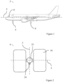
- FIG 1 shows a schematic view of an aircraft 2.
- the aircraft 2 comprises a nose landing gear 4, two main landing gears 6 (only one of which is shown in Figure 1 ) and a cockpit 8.
- a device 10 to steer the nose landing gear 4
- an interface 12 to receive information input by a flight crew
- a display 14 to display information to the flight crew (all shown in Figure 4 ).
- an angle of the nose landing gear 2 relative to a longitudinal axis 5 of the aircraft 2 can be adjusted to alter a trajectory of the aircraft 2 (i.e. to turn the aircraft 2).
- the angle of the nose landing gear 4 relative to the longitudinal axis 5 of the aircraft 2 (also referred to as the aircraft steering angle) is controlled by the flight crew from the cockpit 8 of the aircraft 2.
- the flight crew provides a steering input using the device 10, such as a tiller, in the cockpit 8 and the steering angle of the nose landing gear 4 is changed based on this steering input.
- the aircraft steering angle is negative
- the nose landing gear 4 points towards a starboard side of the aircraft 2 (to the right-hand side of the aircraft 2 when facing forward from the cockpit 8) the aircraft steering angle is positive.
- the nose landing gear 4 has a range of movement of between approximately -90 degrees and +90 degrees.
- FIG 2 shows a schematic plan view of the nose landing gear 4.
- the nose landing gear 4 comprises a strut 23 to which is attached a rotary variable differential transformer (RVDT) 24 and two tires 16.
- the RVDT 24 is configured to measure rotation of the nose landing gear 4 which is indicative of the steering angle of the nose landing gear 4.
- the nose landing gear 4 has a steering angle of approximately 0 degrees.
- the nose landing gear 4 is orientated such that an axis of rotation 5 of the tires 16 is substantially perpendicular to a straight line 3 passing through the nose landing gear 4 that is substantially parallel to the longitudinal/roll axis 5 of the aircraft 2, meaning that when thrust is provided by one or more engines of the aircraft 2, the aircraft 2 will travel in a straight line.
- the aircraft 2 includes a system 20 (as shown schematically in Figure 4 ) to advise the flight crew when the steering angle is close to, or exceeds, a threshold above which degradation of the tires 16 of the nose landing gear 4 is expected to occur.
- the system 20 is located on-board the aircraft 2 and comprises a computer 22, a memory 32 and the RVDT 24 that is attached to the nose landing gear 4.
- the system 20 also comprises the device 10, the interface 12 and the display 14 that are located within the cockpit 8.
- the device 10 comprises a tiller that allows the flight crew to steer the aircraft 2 by changing the steering angle of the nose landing gear 6 and the interface 12 is configured to receive information relating to the aircraft from the flight crew.
- Each of the RVDT 24, the device 10, the interface 12 and the display 14 are in communication with the computer 22.
- the computer 22 is configured to receive signals from the RVDT 24, the device 10 and the interface 12, and is configured to output a signal to the display 14.
- the computer 22 is configured to receive a signal from the RVDT 24 that includes information indicative of the steering angle of the nose landing gear 4.
- the computer 22 is configured to compare the information received from the RVDT 24 against the threshold above which degradation of the tires 16 of the nose landing gear 4 is expected to occur.
- the computer 22 is configured to cause an indication 26 to be output on the display 14 within the cockpit 8.
- the indication 26 output on the display comprises a light 27. If the aircraft steering angle is determined by the computer 22 to exceed the threshold, the light 27 is configured to emit a red light, whereas if the aircraft steering angle is determined by the computer 22 to be below the threshold, the light 27 is configured to emit a green light.
- the indication 26 output on the display 14 also comprises a gauge 31 comprising a needle 29 which moves from a first section 28 to a second section 30 as the steering angle of the nose landing gear 4 increases.
- the first section 28 corresponds to the steering angle of the nose landing gear 4 being below the threshold, while the second section 30 corresponds to the steering angle of the nose landing gear 4 being above the threshold.
- at least one of the light 27 and the gauge 31 may be omitted.
- the computer 22 is configured to cause the indication 26 to be output on the display, in other examples (as will be discussed further with respect to the method below) the computer 22 is configured to cause another action to be performed.
- FIG. 5 shows a flow diagram of a computer-implemented method 100.
- the computer-implemented method 100 comprises receiving 102 information indicative of an aircraft steering angle.
- the information indicative of the aircraft steering angle is received by the computer 22 located onboard the aircraft 2.
- the information indicative of the aircraft steering angle is received from the RVDT 24 and is therefore indicative of a measured steering angle.
- the information received from the RVDT 24 also allows the computer 22 to determine a rate of change of the steering angle of the nose landing gear 4. By knowing the rate of change of the steering angle of the nose landing gear 4 is it possible for the computer 22 to predict what the steering angle of the nose landing gear 4 will be if the current rate of change is maintained.
- the method 100 also comprises calculating 104 the threshold above which degradation of the tires 16 of the nose landing gear 4 is expected to occur.
- the threshold may change based on the weight of the aircraft 2. For example, the threshold may be larger when the aircraft 2 is lighter (such as when taxiing from the runway to the gate after landing) and may be smaller when the aircraft 2 is heavier (such as when taxiing from the gate to the runway for take-off).
- calculating 104 the threshold comprises dynamically calculating the threshold based on the weight of the aircraft 2. Dynamically calculating the threshold comprises calculating the threshold for a given point in time based on factors affecting the threshold (such as the weight of the aircraft 2) at the same point in time. The calculation is therefore dynamic as the threshold changes when the factors affecting the threshold change.
- the flight crew When preparing for take-off or landing, the flight crew carry out a checklist which includes inputting into the interface 12 within the cockpit 8 information that is indicative of the weight of the aircraft 2 (such as the total number of people on board the aircraft 2 as well as the total amount of cargo and fuel loaded onto the aircraft 2). As the amount of fuel present on the aircraft will vary between take-off and landing (due to fuel being burned during flight), a fuel burn rate is also used to by the computer 22 to dynamically calculating the weight of the aircraft 2. The dynamically calculated weight of the aircraft 2 is then used to dynamically calculate the threshold.
- a fuel burn rate is also used to by the computer 22 to dynamically calculating the weight of the aircraft 2.
- determining 104 the threshold also comprises taking account of these factors.
- the computer 22 receives information indicative of the speed of the aircraft 2 from an aircraft system and receives information indicative of the ambient environment from an input made by the flight crew into the interface 12. In some examples, calculating 104 the threshold is based only on the weight of the aircraft 2.
- the threshold is discussed as being dynamically calculated in the above example, in other examples the threshold is a predetermined value that is stored in a database. In such examples, the computer 22 obtains the predetermined value of the threshold from the database.
- the method 100 comprises comparing 106 the received information against the threshold.
- the comparison is carried out by the computer 22 onboard the aircraft 2 and comprises determining whether the steering angle of the nose landing gear 4 is close to exceeding, or will exceed, the threshold.
- the computer 22 is configured to determine when the steering angle of the nose landing gear 4 is within a predetermined range of the threshold, which in this example is approximately 15 degrees below the threshold.
- the method 100 comprises causing 108 an action to be performed based on the comparison.
- causing 108 the action to be performed comprises causing an indication 26 to be output on the display 14.
- the computer 22 is configured to output a signal to the display to cause the indication 26 to be output. If the aircraft steering angle is determined to exceed the threshold, a red light is shown on the display 14, whereas if the aircraft steering angle is determined to be below the threshold, a green light is shown on the display 14.
- the indication 26 output on the display 14 also comprises a gauge 31 comprising a needle 29 that moves from a first section 28 to a second section 30 as the steering angle increases.
- the first section 28 corresponds to the aircraft steering angle being below the threshold, while the second section 30 corresponds to the aircraft steering angle being above the threshold.
- causing 108 an action to be performed also comprises causing haptic feedback to be provided through the input 10 in the cockpit 8.
- the computer 22 causes the device 10 to provide physical resistance to steering inputs that would exceed the threshold. As such, the flight crew will have to exert more force through the device 10 to exceed the threshold, ensuring that they are aware of when the threshold is being exceeded.
- causing 108 the action to be performed comprises causing the indication 26 to be output on the display 14 located externally to the aircraft 8.
- the indication 26 may be any indication 26 as discussed herein.
- the method 100 also comprises storing 110 data representative of at least one of the information indicative of the aircraft steering angle, the comparison and the action to be performed.
- the data is stored on the memory 32 that is located on-board the aircraft 2, although in other examples the data may be transmitted to a memory (not shown) located remote from the aircraft 2, such as at a control centre.
- the method 100 subsequently comprises obtaining 112 the stored data from the memory using the computer 22 and analysing 114 the data on the computer 22.
- the data is analysed to determine how often and for how long the threshold is being exceeded. This analysis may then be used to inform future operations of the aircraft 2 to reduce the amount of time that the threshold is exceeded. For example, if the analysis of the data indicates that the threshold is consistently being exceeded when taking a particular taxiing route, it may be desirable to modify the taxiing route or to request a different taxiing route.
- the analysis of the data may also be shared between different aircraft 2 within a fleet to reduce tire wear across the fleet. While in this example the analysis is performed by the computer 22 onboard the aircraft 2, when the data is transmitted to a memory remote from the aircraft 2, the analysis is also carried out on a computing device remote from the aircraft 2.
- FIG. 6 shows a flow diagram of an alternative method 200.
- the method 200 comprises receiving 202 information relating to a cleared taxiing route of the aircraft 2 at the computer 22.
- the flight crew receives a cleared taxiing route from a ground controller at the airport.
- the cleared taxiing route includes information on which taxiways the aircraft 2 should take and therefore what turns will need to be made by the aircraft 2. This information is input into the interface 12 by the flight crew and the computer 22 is configured to receive this information and determine the steering angles of the nose landing gear 4 that would be required for the aircraft 2 to follow the cleared taxiing route.
- the method 200 also comprises calculating 204 the threshold above which degradation of the tires 16 of the nose landing gear 4 is expected to occur.
- the threshold is calculated in the same way as discussed above in relation to the method 100 of Figure 5 .
- the method 200 subsequently comprises comparing 206 the determined steering angles of the nose landing gear 4 that would be required to follow the taxiing route against the threshold. Based on the result of the comparison, the method 200 comprises causing 208 an action to be performed.
- the action comprises using the computer 22 to determine steering instructions which follow the taxiing route while minimising the time spend exceeding the threshold and outputting the steering instructions on the display 14 within the cockpit 8.
- the steering instructions relate to steering inputs that should be made by the flight crew to cause the aircraft 2 to follow the cleared taxi plan while also minimising the amount of time spent exceeding the threshold.
- the flight crew then input the steering inputs using the device 10 in the cockpit 8 to cause the nose landing gear 4 to steer the aircraft 2.
- causing 208 the action to be performed comprises causing the aircraft 2 to substantially autonomously taxi between the runway of the airport and the gate of the airport. In such examples, causing 208 the action to be performed also comprises outputting control instructions to an aircraft system that controls movement of the aircraft 2.
- causing 208 the action to be performed comprises updating the taxiing route based on the result of the comparison.
- the taxiing route entered into the interface 12 by the flight crew includes information on which taxiways the aircraft 2 should take and therefore what turns will need to be made by the aircraft 2.
- the computer 22 compares the turns required by the taxiing route against the threshold and updates the taxiing route (and the instructions for following the taxiing route) such that, when the aircraft 2 follows the updated taxiing route, the amount of time that the aircraft steering angle exceeds the threshold is minimised or eliminated.
- the instructions for following the updated taxiing route are then output on the display 14 within the cockpit 8 of the aircraft 2 to allow the flight crew to follow the updated taxiing route.
- one or more of the steps of calculating 104, 204 the threshold, storing 110 the data, obtaining 112 the stored data and analysing 114 the stored data may be omitted.
- the methods 100, 200 and system 20 described herein make it possible to determine whether the steering angle of the nose landing gear 4 has exceeded, or will exceed, the threshold. This information can then be used to alter operation of the aircraft 2 to minimise, or eliminate, the amount of time that the steering angle of the nose landing gear 4 spends above the threshold. As a result of this, degradation of one or more tires 16 of the nose landing gear 4 may be reduced which may increase the overall lifetime of the tires 16. As the overall lifetime of the tires 16 may be increased, this may reduce maintenance costs associated with the nose landing gear 4 as the tires 16 may be replaced less frequently.
- aircraft steering angle is discussed in relation to the nose landing gear 4, in other examples the aircraft steering angle may comprise a steering angle of the main landing gear 6.
Landscapes
- Engineering & Computer Science (AREA)
- Aviation & Aerospace Engineering (AREA)
- Mechanical Engineering (AREA)
- Automation & Control Theory (AREA)
- Physics & Mathematics (AREA)
- General Physics & Mathematics (AREA)
- Traffic Control Systems (AREA)
- Length Measuring Devices With Unspecified Measuring Means (AREA)
- Tires In General (AREA)
Abstract
Description
- The present invention relates to a method, an aircraft system, a non-transitory computer-readable storage medium and an aircraft.
- During movement of an aircraft on the ground, tires of a landing gear of the aircraft may be subject to forces that wear the tires and reduce their lifetime. It may be desirable to reduce the amount of wear the tires of the aircraft landing gear are subject to.
- According to a first aspect, there is provided a computer-implemented method comprising: receiving information indicative of an aircraft steering angle of an aircraft; comparing the received information against a threshold above which degradation of a tire of a landing gear of the aircraft is expected to occur; and causing an action to be performed based on a result of the comparison.
- By comparing the information indicative of the aircraft steering angle against the threshold, it may be possible to determine whether the aircraft steering angle has exceeded, or will exceed, the threshold. This information can then be used to alter operation of the aircraft to minimise, or eliminate, the amount of time that the aircraft steering angle spends above the threshold. The method according to the first aspect may also help to reduce degradation of one or more tires of the aircraft landing gear by taking some form of relevant action based on the comparison. This may help to increase the overall lifetime of the tires. As the overall lifetime of the tires may be improved, this may reduce maintenance costs of the aircraft landing gear as the tires may not need to be replaced as often as if the method of the first aspect was not used.
- The aircraft steering angle may comprise a steering angle of a nose landing gear of an aircraft and the tires of the aircraft landing gear may be tires of the nose landing gear. The aircraft steering angle may comprise a steering angle of a main landing gear of the aircraft and the tires of the aircraft landing gear may be tires of the main landing gear. The steering angle may be an angle of the landing gear relative to a longitudinal axis (otherwise known as a roll axis) of the aircraft. The longitudinal axis comprises an axis that passes through the aircraft from a nose of the aircraft to a tail of the aircraft and is substantially parallel with the ground when the aircraft is on the ground.
- The computer-implemented method may comprise receiving, at an on-board aircraft system, the information indicative of the aircraft steering angle. The on-board aircraft system may comprise a computer and the computer-implemented method may comprise receiving, at the computer, the information indicative of the aircraft steering angle. The computer-implemented method may comprise comparing the received information against the threshold using the on-board aircraft system. This may allow the comparing to be carried out on-board the aircraft, without the need to transmit data away from the aircraft. The computer-implemented method may comprise causing the action to be performed using the on-board aircraft system. The on-board aircraft system may output a signal in dependence on the comparison to cause the action to be performed.
- The computer-implemented method may comprise receiving, at a remote computing device, the information indicative of the aircraft steering angle. The remote computing device may be located remote from the aircraft. The computer-implemented method may comprise comparing the received information against the threshold at the remote computing device. This may allow the comparison to be carried out remote from the aircraft, which may reduce the computational load of systems on-board the aircraft. The computer-implemented method may comprise causing the action to be performed using the remote computing device. The remote computing device may output a signal in dependence on the comparison to cause the action to be performed.
- The information indicative of the aircraft steering angle may comprise a measured steering angle of the aircraft. This may allow an actual steering angle of the aircraft to be used for the comparison, which may improve the overall accuracy of the comparison.
- The computer-implemented method may comprise receiving the information indicative of the aircraft steering angle from a sensor attached to the aircraft landing gear. The sensor may comprise a rotary variable displacement transducer (RVDT). The RVDT may be configured to output a signal indicative of the aircraft steering angle.
- The computer-implemented method may comprise receiving the information indicative of the aircraft steering angle from a device located within a cockpit of the aircraft. The device may be operable by a flight crew of the aircraft to provide a steering input to change the aircraft steering angle and the information indicative of the aircraft steering angle may comprise the steering input from the flight crew. This may allow the action to be taken before the aircraft steering angle is changed.
- The information indicative of the aircraft steering angle may comprise information indicative of a taxiing route of the aircraft. The information indicative of the taxiing route may be provided by the flight crew, for example by being input into an interface in the cockpit. The information indicative of the taxiing route may be received from a source external to the aircraft, such as from a ground controller at an airport. The information indicative of the taxiing route may indicate what the aircraft steering angle will be at different times during the taxiing route. The information indicative of the aircraft steering angle may comprise an expected aircraft steering angle that is determined based on a taxiing route to and/or from a runway.
- The information indicative of the aircraft steering angle may comprise a rate of change of the aircraft steering angle. The rate of change of the aircraft steering angle may be used to predict whether the threshold will be exceeded if the current rate of change is maintained. This may allow the action to be performed before the threshold is exceeded.
- The computer-implemented method may comprise causing the action to be performed when the steering angle is within a predefined range of the threshold. The predefined range may be a predetermined angle range below the threshold. The predefined range may be between approximately 5 degrees and 25 degrees below the threshold, such as between approximately 10 degrees and 20 degrees below the threshold. This may allow the action to be taken before the threshold is exceeded, which may help to reduce wear on the tires of the aircraft landing gear.
- Causing the action to be performed may comprise causing an indication to be output. The indication may be output on a display in a cockpit of the aircraft. The indication may inform the flight crew when the aircraft steering angle is close to, or exceeds, the threshold. The flight crew may then take action to prevent the steering angle exceeding the threshold, or to reduce the amount of time that the aircraft steering angle exceeds the threshold. The indication may comprise a light on the display and the causing the action to be performed may comprise causing a property of the light to change, such as the colour of the light, based on the result of the comparison. This may allow an operator, such as a member of flight crew, to quickly and easily see the output.
- The indication may be output on a device external from the aircraft. The device external from the aircraft may be located on a vehicle used to assist the aircraft to move on the ground, such as a towing vehicle. The device external from the aircraft may be a handheld device that can be carried around. When the indication is provided on the device external from the aircraft, this may inform an operator of the device that the aircraft steering angle is close to, or exceeds, the threshold. The operator may then take appropriate action, such as moving the towing vehicle to change the aircraft steering angle, to prevent the steering angle from exceeding the threshold, or to reduce the amount of time that the aircraft steering angle exceeds the threshold.
- Causing the action to be performed may comprise providing instructions for steering the landing gear of the aircraft during a taxiing procedure of the aircraft. The instructions may be provided by an onboard computer to an aircraft system responsible for controlling movement of the aircraft. The instructions may be configured to minimise the amount of time that the aircraft steering angle will exceed the threshold or to avoid the aircraft steering angle exceeding the threshold. As such, this may help to increase the lifetime of the tires of the aircraft landing gear.
- The computer-implemented method may comprise causing the instructions to be automatically carried out by one or more aircraft systems of the aircraft. This may allow the aircraft to substantially autonomously move between a first position and a second position, such as between a gate of an airport and a runway of an airport, while minimising the time that the aircraft steering angle exceeds the threshold or avoiding the aircraft steering angle exceeding the threshold.
- The instructions may be manually carried out by the crew to control movement of the aircraft. The instructions may comprise taxi-way positions and/or turn angles to be carried out during taxiing.
- Causing the action to be performed may comprise providing haptic feedback on a device within the cockpit of the aircraft. The device may be a tiller that is used to change the aircraft steering angle. The haptic feedback may require the flight crew to apply an increased force through the device in order to exceed the threshold. This may help to provide a physical indication to the flight crew as to when the threshold is exceeded.
- Causing the action to be performed may comprise updating the taxiing route based on the comparison. The taxiing route may be updated by the on-board aircraft system or the remote computing device. The taxiing route may be updated such that when the aircraft follows the updated taxiing route, the aircraft steering angle does not exceed the threshold or the amount of time that the aircraft steering angle exceeds the threshold is minimised. The computer-implemented method may comprise outputting instructions for steering the aircraft landing gear to follow the updated taxiing route. The instructions may be output on the display within the cockpit of the aircraft. This may allow the flight crew to see the instructions and operate the aircraft accordingly to follow the taxiing route. The computer-implemented method may comprise causing the instructions to be automatically carried out by one or more aircraft systems. This may allow the aircraft to substantially autonomously follow the updated taxiing route.
- The threshold may comprise an aircraft steering angle of between approximately 30 degrees and 80 degrees relative to the longitudinal axis of the aircraft, such as between approximately 50 degrees and 75 degrees relative to the longitudinal axis of the aircraft. The threshold may comprise an aircraft steering angle that is equal to a maximum possible steering angle of the aircraft.
- The computer-implemented method may comprise calculating the threshold. Calculating the threshold may comprise dynamically calculating the threshold based on an input from an aircraft system. The input may comprise information indicative of at least one of a speed of the aircraft and a weight of the aircraft. The weight of the aircraft may be determined based on a load sheet and/or a fuel burn rate. The weight of the aircraft may be determined based on information provided by the flight crew. By dynamically calculating the threshold, this may allow for a more accurate calculation of the threshold at a given point in time.
- The threshold may be obtained from a database. The computer-implemented method may comprise calculating the threshold based on at least one of a taxiing route of the aircraft, an ambient environment of the aircraft (such as weather conditions at an airport and/or a runway) and one or more properties of the aircraft. The one or more properties of the aircraft may comprise at least one of a weight of the aircraft, the type of aircraft and the age of tires of the aircraft landing gear.
- The computer-implemented method may comprise storing, on a memory, data representative of at least one of the information indicative of an aircraft steering angle and the result of the comparison. The method may comprise transmitting the data to a memory located remote from the aircraft. The memory may be on-board the aircraft or may be remote from the aircraft.
- The computer-implemented method may comprise obtaining the stored data from the memory using a computing device and analysing the data on the computing device. The analysis of the data may be used to inform future decisions regarding taxiing routes to be used to used by aircraft at the airport to minimise the amount of time that the aircraft steering angle exceeds the threshold. The analysis of the data may also be used to guide future airport and/or taxiway design.
- According to a second aspect, there is provided an aircraft system configured to: receive information indicative of an aircraft steering angle of an aircraft; compare the received information against a threshold above which degradation of a tire of a landing gear of the aircraft is expected to occur; and cause an action to be performed based on the result of the comparison.
- According to a third aspect, there is provided a non-transitory computer-readable storage medium storing instructions that, when executed by an aircraft system, cause the aircraft system to carry out the computer-implemented method according to the first aspect.
- According to a fourth aspect, there is provided an aircraft comprising the aircraft system according to the second aspect or the non-transitory computer-readable storage medium according to the third aspect.
- Embodiments of the invention will now be described, by way of example only, with reference to the accompanying drawings, in which:
-
Figure 1 shows a schematic view of an aircraft; -
Figures 2 and3 show schematic plan views of a nose landing gear of the aircraft at different aircraft steering angles; -
Figure 4 shows a schematic view of a system; and -
Figures 5 and6 show flow diagrams of methods. -
Figure 1 shows a schematic view of anaircraft 2. Theaircraft 2 comprises anose landing gear 4, two main landing gears 6 (only one of which is shown inFigure 1 ) and acockpit 8. Within thecockpit 8 is located adevice 10 to steer thenose landing gear 4, aninterface 12 to receive information input by a flight crew and adisplay 14 to display information to the flight crew (all shown inFigure 4 ). During movement of theaircraft 2 on the ground, such as when moving from a gate of an airport to a runway, an angle of thenose landing gear 2 relative to alongitudinal axis 5 of the aircraft 2 (also known as a roll axis of the aircraft 2) can be adjusted to alter a trajectory of the aircraft 2 (i.e. to turn the aircraft 2). - The angle of the
nose landing gear 4 relative to thelongitudinal axis 5 of the aircraft 2 (also referred to as the aircraft steering angle) is controlled by the flight crew from thecockpit 8 of theaircraft 2. The flight crew provides a steering input using thedevice 10, such as a tiller, in thecockpit 8 and the steering angle of thenose landing gear 4 is changed based on this steering input. When thenose landing gear 4 points towards a port side of the aircraft 2 (to the left-hand side of theaircraft 2 when facing forward from the cockpit 8) the aircraft steering angle is negative, and when thenose landing gear 4 points towards a starboard side of the aircraft 2 (to the right-hand side of theaircraft 2 when facing forward from the cockpit 8) the aircraft steering angle is positive. Thenose landing gear 4 has a range of movement of between approximately -90 degrees and +90 degrees. -
Figure 2 shows a schematic plan view of thenose landing gear 4. Thenose landing gear 4 comprises astrut 23 to which is attached a rotary variable differential transformer (RVDT) 24 and twotires 16. TheRVDT 24 is configured to measure rotation of thenose landing gear 4 which is indicative of the steering angle of thenose landing gear 4. InFigure 4 , thenose landing gear 4 has a steering angle of approximately 0 degrees. Thenose landing gear 4 is orientated such that an axis ofrotation 5 of thetires 16 is substantially perpendicular to astraight line 3 passing through thenose landing gear 4 that is substantially parallel to the longitudinal/roll axis 5 of theaircraft 2, meaning that when thrust is provided by one or more engines of theaircraft 2, theaircraft 2 will travel in a straight line. -
Figure 3 shows a schematic plan view of the samenose landing gear 4 as inFigure 2 after a steering input has been provided by the flight crew such that thenose landing gear 4 has a steering angle θ of approximately +40 degrees relative to thestraight line 3 passing through thenose landing gear 4 that is substantially parallel to the longitudinal/roll axis 5 of theaircraft 2. As such, thenose landing gear 4 points to the right and theaircraft 2 will turn to the right when thrust is provided by one or more engines of theaircraft 2. - As the steering angle of the
nose landing gear 4 increases, thetires 16 of thenose landing gear 4 may experience an increase in forces (such as lateral forces) acting upon them, which may speed up degradation of thetires 16. To reduce the wear on thetires 16, theaircraft 2 includes a system 20 (as shown schematically inFigure 4 ) to advise the flight crew when the steering angle is close to, or exceeds, a threshold above which degradation of thetires 16 of thenose landing gear 4 is expected to occur. - The
system 20 is located on-board theaircraft 2 and comprises acomputer 22, amemory 32 and theRVDT 24 that is attached to thenose landing gear 4. Thesystem 20 also comprises thedevice 10, theinterface 12 and thedisplay 14 that are located within thecockpit 8. As discussed above, thedevice 10 comprises a tiller that allows the flight crew to steer theaircraft 2 by changing the steering angle of thenose landing gear 6 and theinterface 12 is configured to receive information relating to the aircraft from the flight crew. Each of theRVDT 24, thedevice 10, theinterface 12 and thedisplay 14 are in communication with thecomputer 22. Thecomputer 22 is configured to receive signals from theRVDT 24, thedevice 10 and theinterface 12, and is configured to output a signal to thedisplay 14. - The
computer 22 is configured to receive a signal from theRVDT 24 that includes information indicative of the steering angle of thenose landing gear 4. Thecomputer 22 is configured to compare the information received from theRVDT 24 against the threshold above which degradation of thetires 16 of thenose landing gear 4 is expected to occur. - Based on the comparison, the
computer 22 is configured to cause anindication 26 to be output on thedisplay 14 within thecockpit 8. As shown inFigure 4 , theindication 26 output on the display comprises a light 27. If the aircraft steering angle is determined by thecomputer 22 to exceed the threshold, the light 27 is configured to emit a red light, whereas if the aircraft steering angle is determined by thecomputer 22 to be below the threshold, the light 27 is configured to emit a green light. - To allow the flight crew to see when the steering angle of the
nose landing gear 4 is nearing the threshold, theindication 26 output on thedisplay 14 also comprises agauge 31 comprising aneedle 29 which moves from afirst section 28 to asecond section 30 as the steering angle of thenose landing gear 4 increases. Thefirst section 28 corresponds to the steering angle of thenose landing gear 4 being below the threshold, while thesecond section 30 corresponds to the steering angle of thenose landing gear 4 being above the threshold. In some examples, at least one of the light 27 and thegauge 31 may be omitted. - While in the example of
Figure 4 , thecomputer 22 is configured to cause theindication 26 to be output on the display, in other examples (as will be discussed further with respect to the method below) thecomputer 22 is configured to cause another action to be performed. -
Figure 5 shows a flow diagram of a computer-implementedmethod 100. The computer-implementedmethod 100 comprises receiving 102 information indicative of an aircraft steering angle. The information indicative of the aircraft steering angle is received by thecomputer 22 located onboard theaircraft 2. When using thesystem 20 discussed above in relation toFigure 4 , the information indicative of the aircraft steering angle is received from theRVDT 24 and is therefore indicative of a measured steering angle. The information received from theRVDT 24 also allows thecomputer 22 to determine a rate of change of the steering angle of thenose landing gear 4. By knowing the rate of change of the steering angle of thenose landing gear 4 is it possible for thecomputer 22 to predict what the steering angle of thenose landing gear 4 will be if the current rate of change is maintained. - The
method 100 also comprises calculating 104 the threshold above which degradation of thetires 16 of thenose landing gear 4 is expected to occur. As the force on thetires 16 is affected by the weight of the aircraft 2 (amongst other factors), the threshold may change based on the weight of theaircraft 2. For example, the threshold may be larger when theaircraft 2 is lighter (such as when taxiing from the runway to the gate after landing) and may be smaller when theaircraft 2 is heavier (such as when taxiing from the gate to the runway for take-off). To account for this, calculating 104 the threshold comprises dynamically calculating the threshold based on the weight of theaircraft 2. Dynamically calculating the threshold comprises calculating the threshold for a given point in time based on factors affecting the threshold (such as the weight of the aircraft 2) at the same point in time. The calculation is therefore dynamic as the threshold changes when the factors affecting the threshold change. - When preparing for take-off or landing, the flight crew carry out a checklist which includes inputting into the
interface 12 within thecockpit 8 information that is indicative of the weight of the aircraft 2 (such as the total number of people on board theaircraft 2 as well as the total amount of cargo and fuel loaded onto the aircraft 2). As the amount of fuel present on the aircraft will vary between take-off and landing (due to fuel being burned during flight), a fuel burn rate is also used to by thecomputer 22 to dynamically calculating the weight of theaircraft 2. The dynamically calculated weight of theaircraft 2 is then used to dynamically calculate the threshold. - As other factors, such as the ground speed of the
aircraft 2 and the ambient environment of the aircraft 2 (such as weather conditions at the airport), also affect the force on thetires 16, determining 104 the threshold also comprises taking account of these factors. Thecomputer 22 receives information indicative of the speed of theaircraft 2 from an aircraft system and receives information indicative of the ambient environment from an input made by the flight crew into theinterface 12. In some examples, calculating 104 the threshold is based only on the weight of theaircraft 2. - While the threshold is discussed as being dynamically calculated in the above example, in other examples the threshold is a predetermined value that is stored in a database. In such examples, the
computer 22 obtains the predetermined value of the threshold from the database. - After calculating the threshold, the
method 100 comprises comparing 106 the received information against the threshold. The comparison is carried out by thecomputer 22 onboard theaircraft 2 and comprises determining whether the steering angle of thenose landing gear 4 is close to exceeding, or will exceed, the threshold. To determine when the steering angle of thenose landing gear 4 is close to exceeding the threshold, thecomputer 22 is configured to determine when the steering angle of thenose landing gear 4 is within a predetermined range of the threshold, which in this example is approximately 15 degrees below the threshold. - Based on the result of the comparison, the
method 100 comprises causing 108 an action to be performed based on the comparison. In the example discussed above in relation to thesystem 20 ofFigure 4 , causing 108 the action to be performed comprises causing anindication 26 to be output on thedisplay 14. Thecomputer 22 is configured to output a signal to the display to cause theindication 26 to be output. If the aircraft steering angle is determined to exceed the threshold, a red light is shown on thedisplay 14, whereas if the aircraft steering angle is determined to be below the threshold, a green light is shown on thedisplay 14. - As shown in
Figure 4 , theindication 26 output on thedisplay 14 also comprises agauge 31 comprising aneedle 29 that moves from afirst section 28 to asecond section 30 as the steering angle increases. Thefirst section 28 corresponds to the aircraft steering angle being below the threshold, while thesecond section 30 corresponds to the aircraft steering angle being above the threshold. - As well as causing the
indication 26 to be output on thedisplay 14, causing 108 an action to be performed also comprises causing haptic feedback to be provided through theinput 10 in thecockpit 8. Based on the result of the comparison, thecomputer 22 causes thedevice 10 to provide physical resistance to steering inputs that would exceed the threshold. As such, the flight crew will have to exert more force through thedevice 10 to exceed the threshold, ensuring that they are aware of when the threshold is being exceeded. - While in this example the
display 14 is located in thecockpit 8 of theaircraft 2, in other examples, thedisplay 14 is located external to the aircraft, such as in a towing vehicle that is used to tow theaircraft 2 while on the ground. In such an example, causing 108 the action to be performed comprises causing theindication 26 to be output on thedisplay 14 located externally to theaircraft 8. Theindication 26 may be anyindication 26 as discussed herein. - The
method 100 also comprises storing 110 data representative of at least one of the information indicative of the aircraft steering angle, the comparison and the action to be performed. The data is stored on thememory 32 that is located on-board theaircraft 2, although in other examples the data may be transmitted to a memory (not shown) located remote from theaircraft 2, such as at a control centre. - The
method 100 subsequently comprises obtaining 112 the stored data from the memory using thecomputer 22 and analysing 114 the data on thecomputer 22. The data is analysed to determine how often and for how long the threshold is being exceeded. This analysis may then be used to inform future operations of theaircraft 2 to reduce the amount of time that the threshold is exceeded. For example, if the analysis of the data indicates that the threshold is consistently being exceeded when taking a particular taxiing route, it may be desirable to modify the taxiing route or to request a different taxiing route. The analysis of the data may also be shared betweendifferent aircraft 2 within a fleet to reduce tire wear across the fleet. While in this example the analysis is performed by thecomputer 22 onboard theaircraft 2, when the data is transmitted to a memory remote from theaircraft 2, the analysis is also carried out on a computing device remote from theaircraft 2. -
Figure 6 shows a flow diagram of analternative method 200. Themethod 200 comprises receiving 202 information relating to a cleared taxiing route of theaircraft 2 at thecomputer 22. When theaircraft 2 is due to taxi to and/or from the runway of the airport, the flight crew receives a cleared taxiing route from a ground controller at the airport. The cleared taxiing route includes information on which taxiways theaircraft 2 should take and therefore what turns will need to be made by theaircraft 2. This information is input into theinterface 12 by the flight crew and thecomputer 22 is configured to receive this information and determine the steering angles of thenose landing gear 4 that would be required for theaircraft 2 to follow the cleared taxiing route. - The
method 200 also comprises calculating 204 the threshold above which degradation of thetires 16 of thenose landing gear 4 is expected to occur. The threshold is calculated in the same way as discussed above in relation to themethod 100 ofFigure 5 . - The
method 200 subsequently comprises comparing 206 the determined steering angles of thenose landing gear 4 that would be required to follow the taxiing route against the threshold. Based on the result of the comparison, themethod 200 comprises causing 208 an action to be performed. The action comprises using thecomputer 22 to determine steering instructions which follow the taxiing route while minimising the time spend exceeding the threshold and outputting the steering instructions on thedisplay 14 within thecockpit 8. The steering instructions relate to steering inputs that should be made by the flight crew to cause theaircraft 2 to follow the cleared taxi plan while also minimising the amount of time spent exceeding the threshold. The flight crew then input the steering inputs using thedevice 10 in thecockpit 8 to cause thenose landing gear 4 to steer theaircraft 2. - In some examples, instead of causing the instructions to be output on the
display 14, causing 208 the action to be performed comprises causing theaircraft 2 to substantially autonomously taxi between the runway of the airport and the gate of the airport. In such examples, causing 208 the action to be performed also comprises outputting control instructions to an aircraft system that controls movement of theaircraft 2. - In another example, causing 208 the action to be performed comprises updating the taxiing route based on the result of the comparison. As discussed above, the taxiing route entered into the
interface 12 by the flight crew includes information on which taxiways theaircraft 2 should take and therefore what turns will need to be made by theaircraft 2. Thecomputer 22 compares the turns required by the taxiing route against the threshold and updates the taxiing route (and the instructions for following the taxiing route) such that, when theaircraft 2 follows the updated taxiing route, the amount of time that the aircraft steering angle exceeds the threshold is minimised or eliminated. The instructions for following the updated taxiing route are then output on thedisplay 14 within thecockpit 8 of theaircraft 2 to allow the flight crew to follow the updated taxiing route. - In some examples of the
methods Figures 5 and6 , one or more of the steps of calculating 104, 204 the threshold, storing 110 the data, obtaining 112 the stored data and analysing 114 the stored data may be omitted. - The
methods system 20 described herein make it possible to determine whether the steering angle of thenose landing gear 4 has exceeded, or will exceed, the threshold. This information can then be used to alter operation of theaircraft 2 to minimise, or eliminate, the amount of time that the steering angle of thenose landing gear 4 spends above the threshold. As a result of this, degradation of one ormore tires 16 of thenose landing gear 4 may be reduced which may increase the overall lifetime of thetires 16. As the overall lifetime of thetires 16 may be increased, this may reduce maintenance costs associated with thenose landing gear 4 as thetires 16 may be replaced less frequently. - While in the above examples the aircraft steering angle is discussed in relation to the
nose landing gear 4, in other examples the aircraft steering angle may comprise a steering angle of themain landing gear 6. - It is to be noted that the term "or" as used herein is to be interpreted to mean "and/or", unless expressly stated otherwise.
- The above embodiments are to be understood as illustrative examples of the invention. Further embodiments of the invention are envisaged. It is to be understood that any feature described in relation to any one embodiment may be used alone, or in combination with other features described, and may also be used in combination with one or more features of any other of the embodiments, or any combination of any other of the embodiments. Furthermore, equivalents and modifications not described above may also be employed without departing from the scope of the invention, which is defined in the accompanying claims.
Claims (15)
- A computer-implemented method comprising:receiving information indicative of an aircraft steering angle of an aircraft;comparing the received information against a threshold above which degradation of a tire of a landing gear of the aircraft is expected to occur; andcausing an action to be performed based on a result of the comparison.
- The computer-implemented method according to claim 1, wherein the information indicative of the aircraft steering angle comprises at least one of a measured steering angle of the aircraft and a steering input from a flight crew of the aircraft.
- The computer-implemented method according to claim 1 or claim 2, wherein the information indicative of the aircraft steering angle comprises information indicative of a taxiing route of the aircraft.
- The computer-implemented method according to any one of claims 1 to 3, wherein the information indicative of the aircraft steering angle comprises a rate of change of the aircraft steering angle.
- The computer-implemented method according to any one of claims 1 to 4, comprising causing the action to be performed when the steering angle is within a predefined range of the threshold.
- The computer-implemented method according to any one of claims 1 to 5, wherein causing the action to be performed comprises causing an indication to be output on a display in a cockpit of the aircraft, optionally wherein the indication comprises a light on the display in the cockpit of the aircraft and causing the action to be performed comprises causing a property of the light to change based on the result of the comparison.
- The computer-implemented method according to any one of claims 1 to 6, wherein causing the action to be performed comprises providing instructions for steering the landing gear of the aircraft during a taxiing procedure of the aircraft, optionally comprising causing the instructions to be automatically carried out by one or more aircraft systems of the aircraft.
- The computer-implemented method according to any one of claims 1 to 7, wherein causing the action to be performed comprises providing haptic feedback on a device within a cockpit of the aircraft.
- The computer-implemented method according to any one of claims 1 to 8, comprising calculating the threshold.
- The computer-implemented method according to claim 9, wherein calculating the threshold comprises dynamically calculating the threshold based on an input from an aircraft system.
- The computer-implemented method according to claim 9 or claim 10, wherein calculating the threshold comprises calculating the threshold based on at least one of: a weight of the aircraft; information provided by a flight crew of the aircraft; a taxiing route of the aircraft; an ambient environment of the aircraft; and one or more properties of the aircraft.
- The computer-implemented method according to any one of claims 1 to 11, comprising storing, on a memory, data representative of at least one of the information indicative of the aircraft steering angle, the comparison and the action to be performed, optionally comprising obtaining the stored data from the memory using a computing device and analysing the stored data on the computing device.
- An aircraft system configured to:receive information indicative of an aircraft steering angle of an aircraft;compare the received information against a threshold above which degradation of a tire of a landing gear of the aircraft is expected to occur; andcause an action to be performed based on the result of the comparison.
- A non-transitory computer-readable storage medium storing instructions that, when executed by an aircraft system, cause the aircraft system to carry out the computer-implemented method according to any one of claims 1 to 12.
- An aircraft comprising the aircraft system according to claim 13 or the non-transitory computer-readable storage medium according to claim 14.
Applications Claiming Priority (1)
| Application Number | Priority Date | Filing Date | Title |
|---|---|---|---|
| GB2314921.4A GB2634215A (en) | 2023-09-28 | 2023-09-28 | Reducing tire wear |
Publications (1)
| Publication Number | Publication Date |
|---|---|
| EP4530179A1 true EP4530179A1 (en) | 2025-04-02 |
Family
ID=88696344
Family Applications (1)
| Application Number | Title | Priority Date | Filing Date |
|---|---|---|---|
| EP24197813.9A Pending EP4530179A1 (en) | 2023-09-28 | 2024-09-02 | Reducing tire wear |
Country Status (4)
| Country | Link |
|---|---|
| US (1) | US12565309B2 (en) |
| EP (1) | EP4530179A1 (en) |
| CN (1) | CN119705817A (en) |
| GB (1) | GB2634215A (en) |
Citations (3)
| Publication number | Priority date | Publication date | Assignee | Title |
|---|---|---|---|---|
| US9802696B2 (en) * | 2015-02-05 | 2017-10-31 | Airbus Operations Limited | Method and apparatus for control of a steerable landing gear |
| CN114313234A (en) * | 2022-02-10 | 2022-04-12 | 中国商用飞机有限责任公司 | Multi-wheel landing gear steering system and control method thereof |
| US20220363406A1 (en) * | 2021-03-25 | 2022-11-17 | Airbus Operations Limited | Monitoring system for an aircraft |
Family Cites Families (13)
| Publication number | Priority date | Publication date | Assignee | Title |
|---|---|---|---|---|
| US4613190A (en) * | 1984-04-10 | 1986-09-23 | Crane Co. | Modulator preset circuit |
| GB0606087D0 (en) | 2006-03-27 | 2006-05-03 | Airbus Uk Ltd | Aircraft steering angle warning system |
| FR2963606B1 (en) | 2010-08-05 | 2013-03-08 | Messier Dowty Sa | LIGHTER EQUIPPED WITH A SAFETY DEVICE |
| WO2014184608A2 (en) | 2012-12-19 | 2014-11-20 | Borealis Technical Limited | Control of ground travel and steering in an aircraft with powered main gear drive wheels |
| GB2533179B (en) | 2014-12-10 | 2020-08-26 | Airbus Operations Ltd | Control method and apparatus for an aircraft when taxiing |
| GB2540182A (en) | 2015-07-08 | 2017-01-11 | Airbus Operations Ltd | Aircraft steering system controller |
| FR3072793B1 (en) | 2017-10-24 | 2019-11-01 | Dassault Aviation | AIRCRAFT TRAJECTORY DISPLAY ASSEMBLY |
| FR3072647B1 (en) * | 2017-10-24 | 2019-11-15 | Dassault Aviation | SYSTEM FOR CONTROLLING A LATERAL TRACK OF AN AIRCRAFT INCLUDING A PALONNIER |
| KR102545101B1 (en) | 2017-10-31 | 2023-06-19 | 현대자동차주식회사 | Apparatus and method for informing wear status of tire |
| US10730352B2 (en) | 2018-02-22 | 2020-08-04 | Ford Global Technologies, Llc | System and method for tire wear prognostics |
| EP3807134B1 (en) * | 2018-06-15 | 2024-06-26 | Politecnico di Milano | System for the combined control of braking of a vehicle, particularly of an aircraft, and of the wear of at least one tyre associated to said vehicle |
| FR3097526B1 (en) | 2019-06-19 | 2021-07-02 | Safran Landing Systems | AIRCRAFT LANDING EQUIPPED WITH VISUAL ALERT MEANS FOR REPORTING AN ANGULAR OVERCURRENCE OF AN ORIENTABLE LOWER PART OF THE LANDING |
| US11390380B2 (en) | 2019-10-10 | 2022-07-19 | The Boeing Company | System and method for alleviating structural loads on a pivoting main landing gear of an aircraft in a pivot turn maneuver |
-
2023
- 2023-09-28 GB GB2314921.4A patent/GB2634215A/en active Pending
-
2024
- 2024-09-02 EP EP24197813.9A patent/EP4530179A1/en active Pending
- 2024-09-18 US US18/889,012 patent/US12565309B2/en active Active
- 2024-09-25 CN CN202411343384.7A patent/CN119705817A/en active Pending
Patent Citations (3)
| Publication number | Priority date | Publication date | Assignee | Title |
|---|---|---|---|---|
| US9802696B2 (en) * | 2015-02-05 | 2017-10-31 | Airbus Operations Limited | Method and apparatus for control of a steerable landing gear |
| US20220363406A1 (en) * | 2021-03-25 | 2022-11-17 | Airbus Operations Limited | Monitoring system for an aircraft |
| CN114313234A (en) * | 2022-02-10 | 2022-04-12 | 中国商用飞机有限责任公司 | Multi-wheel landing gear steering system and control method thereof |
Also Published As
| Publication number | Publication date |
|---|---|
| US12565309B2 (en) | 2026-03-03 |
| GB2634215A (en) | 2025-04-09 |
| US20250108911A1 (en) | 2025-04-03 |
| CN119705817A (en) | 2025-03-28 |
| GB202314921D0 (en) | 2023-11-15 |
Similar Documents
| Publication | Publication Date | Title |
|---|---|---|
| RU2435190C1 (en) | Method and apparatus for lateral control of taxiing aircraft | |
| RU2738927C2 (en) | Automatic control system for aircraft braking on runway, aircraft | |
| US7835829B2 (en) | Automatic take-off method and device for an airplane | |
| US9102404B2 (en) | Method for controlling the deceleration on the ground of a vehicle | |
| EP3751541B1 (en) | Judgmental oversteering taxi aid system and method | |
| GB2587205A (en) | Aircraft system | |
| EP4530179A1 (en) | Reducing tire wear | |
| US11094211B2 (en) | Judgmental oversteering taxi aid system and method | |
| WO2021259534A1 (en) | A method for controlling an aircraft when taxiing | |
| US12573306B2 (en) | Taxiing method and apparatus | |
| US12555485B2 (en) | Autonomous taxiing method and apparatus | |
| US20220363406A1 (en) | Monitoring system for an aircraft | |
| US12504767B2 (en) | Heading control system | |
| EP4037965B1 (en) | Aircraft braking system | |
| US12545430B2 (en) | Determining aircraft steering angle | |
| EP4006879A1 (en) | Autonomous taxiing method and apparatus |
Legal Events
| Date | Code | Title | Description |
|---|---|---|---|
| PUAI | Public reference made under article 153(3) epc to a published international application that has entered the european phase |
Free format text: ORIGINAL CODE: 0009012 |
|
| STAA | Information on the status of an ep patent application or granted ep patent |
Free format text: STATUS: THE APPLICATION HAS BEEN PUBLISHED |
|
| AK | Designated contracting states |
Kind code of ref document: A1 Designated state(s): AL AT BE BG CH CY CZ DE DK EE ES FI FR GB GR HR HU IE IS IT LI LT LU LV MC ME MK MT NL NO PL PT RO RS SE SI SK SM TR |
|
| STAA | Information on the status of an ep patent application or granted ep patent |
Free format text: STATUS: REQUEST FOR EXAMINATION WAS MADE |
|
| 17P | Request for examination filed |
Effective date: 20250929 |
|
| GRAP | Despatch of communication of intention to grant a patent |
Free format text: ORIGINAL CODE: EPIDOSNIGR1 |
|
| STAA | Information on the status of an ep patent application or granted ep patent |
Free format text: STATUS: GRANT OF PATENT IS INTENDED |
|
| RIC1 | Information provided on ipc code assigned before grant |
Ipc: B64C 25/50 20060101AFI20260319BHEP Ipc: B64C 25/34 20060101ALI20260319BHEP Ipc: B64C 25/32 20060101ALI20260319BHEP |