EP4530160A1 - Coupled vehicle control device, coupled vehicle control method, and coupled vehicle control program - Google Patents
Coupled vehicle control device, coupled vehicle control method, and coupled vehicle control program Download PDFInfo
- Publication number
- EP4530160A1 EP4530160A1 EP23811727.9A EP23811727A EP4530160A1 EP 4530160 A1 EP4530160 A1 EP 4530160A1 EP 23811727 A EP23811727 A EP 23811727A EP 4530160 A1 EP4530160 A1 EP 4530160A1
- Authority
- EP
- European Patent Office
- Prior art keywords
- angle
- target
- predicted trajectory
- control device
- combination vehicle
- Prior art date
- Legal status (The legal status is an assumption and is not a legal conclusion. Google has not performed a legal analysis and makes no representation as to the accuracy of the status listed.)
- Pending
Links
Images






Classifications
-
- B—PERFORMING OPERATIONS; TRANSPORTING
- B62—LAND VEHICLES FOR TRAVELLING OTHERWISE THAN ON RAILS
- B62D—MOTOR VEHICLES; TRAILERS
- B62D15/00—Steering not otherwise provided for
- B62D15/02—Steering position indicators ; Steering position determination; Steering aids
- B62D15/027—Parking aids, e.g. instruction means
-
- B—PERFORMING OPERATIONS; TRANSPORTING
- B62—LAND VEHICLES FOR TRAVELLING OTHERWISE THAN ON RAILS
- B62D—MOTOR VEHICLES; TRAILERS
- B62D15/00—Steering not otherwise provided for
- B62D15/02—Steering position indicators ; Steering position determination; Steering aids
- B62D15/027—Parking aids, e.g. instruction means
- B62D15/0275—Parking aids, e.g. instruction means by overlaying a vehicle path based on present steering angle over an image without processing that image
-
- B—PERFORMING OPERATIONS; TRANSPORTING
- B60—VEHICLES IN GENERAL
- B60D—VEHICLE CONNECTIONS
- B60D1/00—Traction couplings; Hitches; Draw-gear; Towing devices
- B60D1/24—Traction couplings; Hitches; Draw-gear; Towing devices characterised by arrangements for particular functions
- B60D1/245—Traction couplings; Hitches; Draw-gear; Towing devices characterised by arrangements for particular functions for facilitating push back or parking of trailers
-
- B—PERFORMING OPERATIONS; TRANSPORTING
- B60—VEHICLES IN GENERAL
- B60D—VEHICLE CONNECTIONS
- B60D1/00—Traction couplings; Hitches; Draw-gear; Towing devices
- B60D1/58—Auxiliary devices
- B60D1/62—Auxiliary devices involving supply lines, electric circuits or the like
-
- B—PERFORMING OPERATIONS; TRANSPORTING
- B60—VEHICLES IN GENERAL
- B60K—ARRANGEMENT OR MOUNTING OF PROPULSION UNITS OR OF TRANSMISSIONS IN VEHICLES; ARRANGEMENT OR MOUNTING OF PLURAL DIVERSE PRIME-MOVERS IN VEHICLES; AUXILIARY DRIVES FOR VEHICLES; INSTRUMENTATION OR DASHBOARDS FOR VEHICLES; ARRANGEMENTS IN CONNECTION WITH COOLING, AIR INTAKE, GAS EXHAUST OR FUEL SUPPLY OF PROPULSION UNITS IN VEHICLES
- B60K35/00—Instruments specially adapted for vehicles; Arrangement of instruments in or on vehicles
- B60K35/20—Output arrangements, i.e. from vehicle to user, associated with vehicle functions or specially adapted therefor
- B60K35/21—Output arrangements, i.e. from vehicle to user, associated with vehicle functions or specially adapted therefor using visual output, e.g. blinking lights or matrix displays
- B60K35/22—Display screens
-
- B—PERFORMING OPERATIONS; TRANSPORTING
- B60—VEHICLES IN GENERAL
- B60K—ARRANGEMENT OR MOUNTING OF PROPULSION UNITS OR OF TRANSMISSIONS IN VEHICLES; ARRANGEMENT OR MOUNTING OF PLURAL DIVERSE PRIME-MOVERS IN VEHICLES; AUXILIARY DRIVES FOR VEHICLES; INSTRUMENTATION OR DASHBOARDS FOR VEHICLES; ARRANGEMENTS IN CONNECTION WITH COOLING, AIR INTAKE, GAS EXHAUST OR FUEL SUPPLY OF PROPULSION UNITS IN VEHICLES
- B60K35/00—Instruments specially adapted for vehicles; Arrangement of instruments in or on vehicles
- B60K35/20—Output arrangements, i.e. from vehicle to user, associated with vehicle functions or specially adapted therefor
- B60K35/28—Output arrangements, i.e. from vehicle to user, associated with vehicle functions or specially adapted therefor characterised by the type of the output information, e.g. video entertainment or vehicle dynamics information; characterised by the purpose of the output information, e.g. for attracting the attention of the driver
-
- B—PERFORMING OPERATIONS; TRANSPORTING
- B60—VEHICLES IN GENERAL
- B60W—CONJOINT CONTROL OF VEHICLE SUB-UNITS OF DIFFERENT TYPE OR DIFFERENT FUNCTION; CONTROL SYSTEMS SPECIALLY ADAPTED FOR HYBRID VEHICLES; ROAD VEHICLE DRIVE CONTROL SYSTEMS FOR PURPOSES NOT RELATED TO THE CONTROL OF A PARTICULAR SUB-UNIT
- B60W50/00—Details of control systems for road vehicle drive control not related to the control of a particular sub-unit, e.g. process diagnostic or vehicle driver interfaces
- B60W50/0097—Predicting future conditions
-
- B—PERFORMING OPERATIONS; TRANSPORTING
- B62—LAND VEHICLES FOR TRAVELLING OTHERWISE THAN ON RAILS
- B62D—MOTOR VEHICLES; TRAILERS
- B62D13/00—Steering specially adapted for trailers
- B62D13/06—Steering specially adapted for trailers for backing a normally drawn trailer
-
- B—PERFORMING OPERATIONS; TRANSPORTING
- B62—LAND VEHICLES FOR TRAVELLING OTHERWISE THAN ON RAILS
- B62D—MOTOR VEHICLES; TRAILERS
- B62D15/00—Steering not otherwise provided for
- B62D15/02—Steering position indicators ; Steering position determination; Steering aids
- B62D15/027—Parking aids, e.g. instruction means
- B62D15/0285—Parking performed automatically
-
- G—PHYSICS
- G06—COMPUTING OR CALCULATING; COUNTING
- G06T—IMAGE DATA PROCESSING OR GENERATION, IN GENERAL
- G06T19/00—Manipulating three-dimensional [3D] models or images for computer graphics
- G06T19/006—Mixed reality
Definitions
- the present disclosure relates to control devices for combination vehicles, control methods for combination vehicles, and control programs for combination vehicles.
- Patent Document 1 describes a control device that displays the time it takes for a hitch angle to return to zero in a combination vehicle.
- Patent Document 1 US Patent No. 10112646
- One aspect of the present disclosure provides a control device for a combination vehicle including a tractor and a trailer that is towed by the tractor.
- the control device is configured to perform a state quantity acquisition process, a predicted trajectory information calculation process, and a display process.
- the state quantity acquisition process is a process of acquiring a state quantity of the combination vehicle.
- the predicted trajectory information calculation process is a process of calculating predicted trajectory information of the trailer according to the state quantity.
- the display process is a process of displaying the predicted trajectory information by operating a display device.
- the control method includes a state quantity acquisition process, a predicted trajectory information calculation process, and a display process.
- the state quantity acquisition process is a process of acquiring a state quantity of the combination vehicle.
- the predicted trajectory information calculation process is a process of calculating predicted trajectory information of the trailer according to the state quantity.
- the display process is a process of displaying the predicted trajectory information by operating a display device.
- Still another aspect of the present disclosure provides a control program for a combination vehicle including a tractor and a trailer that is towed by the tractor.
- the control program is a program that causes a computer to perform a state quantity acquisition process, a predicted trajectory information calculation process, and a display process.
- the state quantity acquisition process is a process of acquiring a state quantity of the combination vehicle.
- the predicted trajectory information calculation process is a process of calculating predicted trajectory information of the trailer according to the state quantity.
- the display process is a process of displaying the predicted trajectory information by operating a display device.
- a combination vehicle 10 includes a tractor 20 and a trailer 30.
- the tractor 20 includes front wheels 22 and rear wheels 24.
- the front wheels 22 include two wheels, namely a right front wheel and a left front wheel
- the rear wheels 24 include two wheels, namely a right rear wheel and a left rear wheel.
- FIG. 1 illustrates an enclosed box trailer as the trailer 30.
- the trailer 30 includes wheels 32.
- the wheels 32 include two wheels, namely a right wheel and a left wheel.
- the trailer 30 is connected to the rear of the tractor 20 via a ball joint 40.
- the ball joint 40 is a member that connects the trailer 30 to the tractor 20 so that the trailer 30 can rotate about an axis 42.
- the axis 42 extends in the height direction of the tractor 20.
- FIG. 2 shows some of members of the tractor 20.
- the tractor 20 includes a control device 50.
- the control device 50 operates a steering system 60, a drive system 62, and a brake system 64 in order to control controlled variables of the combination vehicle 10 that is a controlled object.
- the controlled variables include a vehicle speed, a direction of travel, and a hitch angle.
- the hitch angle is an angle between the front-rear direction of the tractor 20 and the front-rear direction of the trailer 30.
Landscapes
- Engineering & Computer Science (AREA)
- Mechanical Engineering (AREA)
- Transportation (AREA)
- Chemical & Material Sciences (AREA)
- Combustion & Propulsion (AREA)
- General Engineering & Computer Science (AREA)
- General Physics & Mathematics (AREA)
- Theoretical Computer Science (AREA)
- Physics & Mathematics (AREA)
- Software Systems (AREA)
- Computer Hardware Design (AREA)
- Computer Graphics (AREA)
- Automation & Control Theory (AREA)
- Human Computer Interaction (AREA)
- Steering Control In Accordance With Driving Conditions (AREA)
Abstract
Description
- The present disclosure relates to control devices for combination vehicles, control methods for combination vehicles, and control programs for combination vehicles.
- For example,
Patent Document 1 below describes a control device that displays the time it takes for a hitch angle to return to zero in a combination vehicle. - Patent Document 1:
US Patent No. 10112646 - With the above control device, it is difficult for a driver to always grasp the behavior of a trailer.
- One aspect of the present disclosure provides a control device for a combination vehicle including a tractor and a trailer that is towed by the tractor. The control device is configured to perform a state quantity acquisition process, a predicted trajectory information calculation process, and a display process. The state quantity acquisition process is a process of acquiring a state quantity of the combination vehicle. The predicted trajectory information calculation process is a process of calculating predicted trajectory information of the trailer according to the state quantity. The display process is a process of displaying the predicted trajectory information by operating a display device.
- Another aspect of the present disclosure provides a control method for a combination vehicle including a tractor and a trailer that is towed by the tractor. The control method includes a state quantity acquisition process, a predicted trajectory information calculation process, and a display process. The state quantity acquisition process is a process of acquiring a state quantity of the combination vehicle. The predicted trajectory information calculation process is a process of calculating predicted trajectory information of the trailer according to the state quantity. The display process is a process of displaying the predicted trajectory information by operating a display device.
- Still another aspect of the present disclosure provides a control program for a combination vehicle including a tractor and a trailer that is towed by the tractor. The control program is a program that causes a computer to perform a state quantity acquisition process, a predicted trajectory information calculation process, and a display process. The state quantity acquisition process is a process of acquiring a state quantity of the combination vehicle. The predicted trajectory information calculation process is a process of calculating predicted trajectory information of the trailer according to the state quantity. The display process is a process of displaying the predicted trajectory information by operating a display device.
-
- [
FIG. 1] FIG. 1 is a perspective view showing the configuration of a combination vehicle according to an embodiment. - [
FIG. 2] FIG. 2 is a block diagram showing the configuration of a control system according to the embodiment. - [
FIG. 3] FIG. 3 is a diagram illustrating reverse control of the combination vehicle according to the embodiment. - [
FIG. 4] FIG. 4 is a diagram showing a model of the combination vehicle according to the embodiment. - [
FIG. 5] FIG. 5 is a flowchart showing the steps of a process that is performed by a control device according to the embodiment. - [
FIG. 6] FIG. 6 is a flowchart showing the steps of the process that is performed by the control device according to the embodiment. - [
FIG. 7] FIGS. 7A and 7B are diagrams showing a method for displaying a predicted trajectory. - [
FIG. 8] FIGS. 8A and 8B are diagrams showing a display example according to the embodiment. - [
FIG. 9] FIGS. 9A and 9B are diagrams showing a display example according to the embodiment. - [
FIG. 10] FIGS. 10A and 10B are diagrams showing a display example according to the embodiment. - [
FIG. 11] FIGS. 11A and 11B are timing charts illustrating control of a virtual steering angle according to the embodiment. - [
FIG. 12] FIGS. 12A and 12B are diagrams showing a display example according to a modification of the embodiment. - [
FIG. 13] FIGS. 13A and 13B are diagrams showing a display example according to a modification of the embodiment. - [
FIG. 14] FIGS. 14A and 14B are diagrams showing a display example according to a modification of the embodiment. - An embodiment of the present invention will be described with reference to the drawings.
- As shown in
FIG. 1 , acombination vehicle 10 includes atractor 20 and atrailer 30. Thetractor 20 includesfront wheels 22 andrear wheels 24. Thefront wheels 22 include two wheels, namely a right front wheel and a left front wheel, and therear wheels 24 include two wheels, namely a right rear wheel and a left rear wheel.FIG. 1 illustrates an enclosed box trailer as thetrailer 30. Thetrailer 30 includeswheels 32. Thewheels 32 include two wheels, namely a right wheel and a left wheel. - The
trailer 30 is connected to the rear of thetractor 20 via aball joint 40. Theball joint 40 is a member that connects thetrailer 30 to thetractor 20 so that thetrailer 30 can rotate about an axis 42. The axis 42 extends in the height direction of thetractor 20. -
FIG. 2 shows some of members of thetractor 20. As shown inFIG. 2 , thetractor 20 includes acontrol device 50. Thecontrol device 50 operates asteering system 60, adrive system 62, and abrake system 64 in order to control controlled variables of thecombination vehicle 10 that is a controlled object. The controlled variables include a vehicle speed, a direction of travel, and a hitch angle. The hitch angle is an angle between the front-rear direction of thetractor 20 and the front-rear direction of thetrailer 30. - The
steering system 60 includes a steering actuator that steers steered wheels. The steered wheels are, for example, thefront wheels 22 shown inFIG. 1 . Thesteering system 60 may include a steering control device that operates the steering actuator. In that case, the "control device 50 operates thesteering system 60" means that thecontrol device 50 outputs command signals to the steering control device. - The
drive system 62 includes at least one of the following two devices as a thrust generation device for the vehicle: an internal combustion engine and a rotating electrical machine. Thedrive system 62 may include a drive control device that controls the internal combustion engine and the rotating electrical machine. In that case, the "control device 50 operates thedrive system 62" means that thecontrol device 50 outputs command signals to the drive control device. - The
brake system 64 includes at least one of the following two devices: a device that reduces the speed of rotation of the wheels using a frictional force, and a device that reduces the speed of rotation of the wheels by converting the power of the wheels to electrical energy. The device that reduces the speed of rotation of the wheels by converting the power of the wheels to electrical energy may be shared with the rotating electrical machine of the drive system. Thebrake system 64 may include a brake control device that controls the devices that reduce the speed of rotation of the wheels. In that case, the "control device 50 operates thebrake system 62" means that thecontrol device 50 outputs command signals to the brake control device. - The
control device 50 refers to a steered angle α1 of the steered wheels detected by asteering angle sensor 70 in order to control the controlled variables. The steered angle α1 is a value that takes a positive sign for one of a right turn and a left turn and takes a negative sign for the other. The steered angle α1 is a turning angle of tires. For example, when thesteering system 60 includes a rack and pinion mechanism, thesteering angle sensor 70 may be a sensor that detects a pinion angle. In that case, however, thecontrol device 50 performs a process of converting the pinion angle to the turning angle of the tires. Hereinafter, for convenience of description, the turning angle of the tires is regarded as a detection value of thesteering angle sensor 70 even if the turning angle of the tires is obtained by the above conversion process. - The
control device 50 also refers to a hitch angle β detected by ahitch angle sensor 72. The hitch angle β may take either a positive sign or a negative sign depending on the angle between the direction of travel of thetractor 20 from rear to front and the direction of travel of thetrailer 30 from rear to front. For example, the hitch angle β may take a positive sign when the direction of travel of thetrailer 30 from rear to front deviates counterclockwise from the direction of travel of thetractor 20 from rear to front by less than 180°. Thecontrol device 50 also refers to wheel speeds ωw1 to ωw4 detected bywheel speed sensors 74. The wheel speeds ωw1, ωw2 are the rotational speed of theright front wheel 22 and the rotational speed of theleft front wheel 22, respectively. The wheel speeds ωw3, ωw4 are the rotational speed of the rightrear wheel 24 and the rotational speed of the leftrear wheel 24, respectively. Thecontrol device 50 also refers to image data Dp that indicates an image of the rear of thetractor 20 captured by abackup camera 76. - The
control device 50 sets control of the controlled variables according to the operating state of auser interface 80. Theuser interface 80 is used to transmit intentions of a user to thecontrol device 50, such as an intention to select one of the following two drivings: autonomous driving and manual driving. - The
control device 50 includes aPU 52 and astorage device 54. ThePU 52 is a software processing device including at least one of the following: a CPU, a GPU, a TPU, etc. Thestorage device 54 stores areverse assist program 54a. Thereverse assist program 54a is a program that defines commands to cause thePU 52 to perform a reverse assist process. The reverse assist process is a process of automatically performing a process of steering the steered wheels when thecombination vehicle 10 reverses. Thereverse assist program 54a is a program for reducing the burden of driving in reverse on the driver. - That is, as shown in
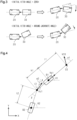
FIG. 3 , when thecombination vehicle 10 reverses, the behavior of thetrailer 30 changes according to the hitch angle β even when the steered angle of thetractor 20 is the same. Therefore, reverse control requires advanced driving skills. The reverse assist process by the reverse assistprogram 54a is a process of assisting the driver by controlling the steered angle α1 of thetractor 20. In the reverse assist process, accelerator operations and brake operations are left to the driver. In the reverse assist process, instructing to steer thetrailer 30 is also left to the driver. This is because requirements for thecontrol device 50 increase if thecontrol device 50 also sets steering of thetrailer 30. Leasing part of instructions to the driver makes it possible to assist in reverse control by a relatively simple process. -
FIG. 4 shows a model of thecombination vehicle 10 that is used in the reverse assist process. In the model shown inFIG. 4 , the pair offront wheels 22 of thetractor 20 is regarded as a single front wheel C0, and the pair ofrear wheels 24 of thetractor 20 is regarded as a single rear wheel B1. That is, a two-wheel model is used for thetractor 20. The pair ofwheels 32 of thetrailer 30 is regarded as a single wheel B2. The angle between a line determined by the front wheel C0 and a hitch point C1 and a line determined by the hitch point C1 and the wheel B2 is the hitch angle β. The hitch point C1 corresponds to a portion at the axis 42 inFIG. 1 . A front wheel speed VC0, namely the speed of the front wheel C0, is a vector that moves in the direction of the steered angle α1. The steered angle α1 is modeled as an angle between the direction in which the front wheel C0 moves and the line determined by the front wheel C0 and the hitch point C1. The direction of a vehicle speed Vb1 is parallel to the line determined by the front wheel C0 and the hitch point C1. In the following description, it is assumed that the vehicle speed Vb1 takes a positive sign when thetractor 20 travels forward. The angle between the direction of the vehicle speed Vb1 and the x direction inFIG. 4 is an angle θ1. The angle between the line connecting the wheel B2 and the hitch point C1 and the x direction is an angle θ2. A distance l1 between the front wheel C0 and the rear wheel B1, a distance h1 between the rear wheel B1 and the hitch point C1, and a distance l2 between the hitch point C1 and the wheel B2 are defined. - In the present embodiment, a virtual steering angle α2 that quantifies steering of the
trailer 30 is defined as shown inFIG. 4 . In other words, it is defined as an angle between the direction of the moving speed at the hitch point C1 and the front-rear direction of thetrailer 30. -
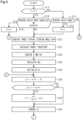
FIGS. 5 and6 show the steps of a process related to the reverse assist process. The process shown inFIGS. 5 and6 is implemented by thePU 52 repeatedly executing thereverse assist program 54a in, for example, predetermined cycles. In the following description, the numbers preceded by the letter "S" represent step numbers of each process. - In the series of processes shown in
FIGS. 5 and6 , thePU 52 first determines whether a reverse assist flag F is "1" (S10). When the reverse assist flag F is "1," it indicates that a reverse assist mode for performing the reverse assist process is selected. On the other hand, when the reverse assist flag F is "0," it indicates that the reverse assist mode is not selected. When it is determined that the reverse assist flag F is "0" (S10: NO), thePU 52 determines whether the reverse assist mode is selected (S12). ThePU 52 determines that the reverse assist mode is selected when an instruction to perform the reverse assist process is sent according to an input operation performed on theuser interface 80. When thePU 52 determines that the reverse assist mode is selected (S12: YES), thePU 52 sets the reverse assist flag F to "1" (S14). - When the
PU 52 determines that the reverse assist flag F is "1" (S10: YES), thePU 52 determines whether a logical disjunction of the following conditions (A), (B) is true (S16). - Condition (A): a condition that the reverse assist mode has been cancelled according to an input operation performed on the
user interface 80. - Condition (B): a condition that the vehicle speed Vb1 is equal to or higher than a threshold Vth. In other words, the condition (B) is a condition that the magnitude of the forward traveling speed of the
tractor 20 is equal to or higher than the threshold Vth. This process is a condition that the driver is presumed to be in a situation in which he or she has stopped reverse control of thecombination vehicle 10 and is about to move thecombination vehicle 10 significantly. - When the
PU 52 determines that the logical disjunction is true (S16: YES), thePU 52 sets the reverse assist flag F to "0" (S18). When thePU 52 determines that the logical disjunction is false (S16: NO) or when thePU 52 completes the process of S14, thePU 52 acquires a target virtual steering angle α2* according to an input operation performed on the user interface 80 (S20). The target virtual steering angle α2* is a target value of a virtual steering angle α2. In the present embodiment, the target virtual steering angle α2* is specified by the driver. Specifically, for example, the input operation may be implemented by providing theuser interface 80 with a dial having a positive correlation with the virtual steering angle α2. The rotation angle of the dial and the target virtual steering angle α2* need not necessarily have a proportional relationship. - The
PU 52 then calculates a target trajectory Trt of thetrailer 30 using the target virtual steering angle α2* as an input (S22). ThePU 52 may calculate the target trajectory Trt using a two-wheel model in which the hitch point C1 is a front wheel that is a steered wheel and the rear wheel B1 is a rear wheel. More specifically, thePU 52 may calculate the target trajectory Trt by calculating the curvature of the target trajectory Trt according to the target virtual steering angle α2* and the distance l2. The target trajectory Trt may be the trajectory of a representative point of thetrailer 30. The representative point may be, for example, the center point of the rear wheel B1. Alternatively, the representative point may be, for example, the center of gravity of thetrailer 30. - The
PU 52 then acquires the hitch angle β and the vehicle speed Vb1 (S24). The hitch angle β is the most recent detection value from thehitch angle sensor 72. The vehicle speed Vb1 is calculated by thePU 52 based on the wheel speeds ωw3, ωw4. For example, the vehicle speed Vb1 may be a simple average value of the wheel speeds ωw3, ωw4. - The
PU 52 then calculates the speed Vb2 of the wheel B2 (S25). More specifically, thePU 52 calculates the speed Vb2 from a geometric relationship according to the hitch angle β and the vehicle speed Vb1. ThePU 52 then initializes the angle θ1 (S26). In this example, thePU 52 sets the angle θ1 to "90°." This is a setting for setting the front-rear direction of thetractor 20 as the y direction of the coordinate system shown inFIG. 4 . - The
PU 52 then calculates a target steered angle α1* that is a steered angle for achieving the target virtual steering angle α2* (S28). The process of S28 is a process in which the target virtual steering angle α2* and the hitch angle β are input and the target steered angle α1* is output. That is, according to the model shown inFIG. 4 , the following equation (c1) holds between the steered angle α1 and the virtual steering angle α2.
- When the virtual steering angle α2 on the right side of the above equation (c1) is replaced with the target virtual steering angle α2*, the left side becomes the target steered angle α1*.
- The
PU 52 may calculate the target steered angle α1* based on an equation according to the equation (c1). ThePU 52 may perform a map calculation to calculate the target steered angle α1*. This can be implemented by storing map data in advance in thestorage device 54. The map data is data that uses the target virtual steering angle α2* and the hitch angle β as input variables and the target steered angle α1* as an output variable. The map data is a data set of discrete values of the input variables and values of the output variable corresponding to the values of the input variables. The map calculation may be a process in which, when the values of the input variables match any of the values of the input variables in the map data, a corresponding value of the output variable in the map data is output as a calculation result. The map calculation may be a process in which, when the values of the input variables do not match any of the values of the input variables in the map data, a value obtained by interpolating a plurality of values of the output variable included in the map data is output as a calculation result. Alternatively, the map computation may be a process in which, when the values of the input variables do not match any of the values of the input variables in the map data, the value of the output variable in the map data that corresponds to the values of the input variables in the map data closest to the values of the input variables, out of the plurality of values of the input variables included in the map data, is output as a calculation result. - The
PU 52 then determines whether the magnitude of the target steered angle α1* is larger than an upper limit value α1th (S30). The upper limit value α1th is the maximum possible value of the steered angle α1. This process is a process of determining whether the steered angle α1 that achieves the target virtual steering angle α2* can actually be achieved. When thePU 52 determines that the target steered angle α1* is larger than the upper limit value α1th (S30: YES), thePU 52 reduces the magnitude of the target steered angle α1* to the upper limit value α1th (S32). - When the
PU 52 completes the process of S32 or when NO in the process of S30, thePU 52 operates thesteering system 60 to control the steered angle α1 toward the target steered angle α1* (S34). - Referring to
FIG. 6 , thePU 52 predicts a future hitch angle β, namely the hitch angle β in a predetermined time τ (S36). According to the model shown inFIG. 4 , the amount of change Δβ in hitch angle β during the predetermined time τ is given by the following equation (c2). -

PU 52 may calculate a predicted value of the hitch angle β by adding the amount of change Δβ calculated by the above equation (c2) to the hitch angle β. Alternatively, the process of S36 may be configured to include a process in which thePU 52 calculates the amount of change Δβ by a map calculation using map data stored in advance. The map data is data that uses the vehicle speed Vb1, the hitch angle β, and the target steered angle α1* as input variables and the amount of change Δβ in hitch angle β as an output variable. - The
PU 52 then calculates a future angle θ1, namely the angle θ1 in the predetermined time τ (S38). The amount of change Δθ1 in angle θ1 during the predetermined time τ is given by the following equation (c3).
- In the process of S36, the
PU 52 may calculate a predicted value of the angle θ1 by adding the amount of change Δθ1 calculated by the above equation (c3) to the angle θ1. Alternatively, in the process of S36, thePU 52 may calculate the amount of change Δθ1 by a map calculation using map data stored in advance. The map data is data that uses the vehicle speed Vb1 and the target steered angle α1* as input variables and the amount of change Δθ1 as an output variable. - The
PU 52 substitutes the sum of the hitch angle β calculated in the process of S36 and the angle θ1 calculated in the process of S38 for the future angle θ2, namely the angle θ2 in the predetermined time τ (S40). ThePU 52 then receives the vehicle speed Vb1 and the angle θ1 as inputs and calculates future tractor position coordinates (xb1, yb1), namely tractor position coordinates (xb1, yb1) in the predetermined time τ (S44). The amount of change in x-component xb1 of the tractor position coordinates during the predetermined time τ is "Vb1·cosθ1." The amount of change in y-component yb1 of the tractor position coordinates during the predetermined time τ is "Vb1·sinθ1." - The
PU 52 then receives the speed Vb2 and the angle θ2 as inputs and calculates the future trailer position coordinates (xb2, yb2), namely the trailer position coordinates (xb2, yb2) in the predetermined time τ (S46). The amount of change in x-component xb2 of the trailer position coordinates during the predetermined time τ is "Vb2·cosθ2." The amount of change in y-component yb2 of the trailer position coordinates during the predetermined time τ is "Vb2·sinθ2." - The
PU 52 then temporarily stores the values calculated in the processes of S28 to S32 and S36 to S46 in the storage device 54 (S48). That is, thePU 52 temporarily stores in thestorage device 54 the tractor position coordinates (xb1, yb1), the trailer position coordinates (xb2, yb2), the angles θ1, θ2, the target steered angle α1*, and the hitch angle β. - The
PU 52 then determines whether a prediction section has ended (S50). The prediction section is a section in which thecombination vehicle 10 travels for a predetermined time. The predetermined time may be, for example, about a few seconds. The prediction section may have a positive correlation with the absolute value of the vehicle speed Vb1, or need not be dependent on the vehicle speed Vb1. - When the
PU 52 determines that the prediction section has not ended (S50: NO), the routine returns to the process of S28. On the other hand, when thePU 52 determines that the prediction section has ended (S50: YES), thePU 52 displays the predicted trajectory Trp and the target trajectory Trt on adisplay device 82 shown inFIG. 1 (S52). It is desirable that the process of S34 be performed only once before the determination in the process of S50 is YES. - At the time it is determined that the prediction section has ended, N hitch angles β that are ahead in time of the hitch angle β acquired in the process of S24 has been stored in the
storage device 54. N is an integer of 2 or more. These are predicted values obtained at intervals of the predetermined time τ. The tractor position coordinates (xb1, yb1), trailer position coordinates (xb2, yb2), angles θ1, θ2, and target steered angles α1* at the timings synchronized with the N hitch angles β have also been stored in thestorage device 54. - The N trailer position coordinates (xb2, yb2) indicate predicted positions of the representative point of the
trailer 30 that are separated from each other by the predetermined time τ. The predicted trajectory Trp can be obtained by connecting them. - The process of S52 may be a process of sending the N trailer position coordinates (xb2, yb2) to the
display device 82. The process of S52 may be a process of finding a curve that fits the N trailer position coordinates (xb2, yb2) and sending parameters that identify the curve to thedisplay device 82. In this case, the communication load can be reduced. Thedisplay device 82 may have only a simple display function, and thePU 52 may generate an image to be displayed on thedisplay device 82. - The
display device 82 superimposes the predicted trajectory Trp and the target trajectory Trt on an image captured by thebackup camera 76, and displays the resultant image.FIG. 7A shows the predicted trajectory Trp obtained by connecting the trailer position coordinates (xb2, yb2), and the target trajectory Trt. According to the process of S26, the trailer position coordinates (xb2, yb2) are coordinate components of a coordinate system in which the y-axis is parallel to the front-rear direction of thetractor 20. However, in order to match the trailer position coordinates (xb2, yb2) with the image from thebackup camera 76, thePU 52 displays point cloud data etc. obtained by projective transformation of the trailer position coordinates (xb2, yb2) as shown inFIG. 7B . -
FIGS. 8A and 8B show an example of the image that is displayed on adisplay screen 82a of thedisplay device 82. Specifically,FIG. 8A shows the state of thecombination vehicle 10, andFIG. 8B shows an example of the display on thedisplay screen 82a. InFIGS. 8A and 8B , the predicted trajectory Trp is shown by a continuous line, and the target trajectory Trt is shown by a long dashed short dashed line. However, the predicted trajectory Trp and the target trajectory Trt may be displayed in different colors on theactual display screen 82a so that they can be distinguished from each other. The example shown inFIGS. 8A and 8B illustrates a case where the driver wants to turn right while reversing. -
FIGS. 9A and 9B show another example of the image that is displayed on thedisplay screen 82a of thedisplay device 82.FIGS. 9A and 9B correspond toFIGS. 8A and 8B . The example shown inFIGS. 9A and 9B shows a case where the driver wants to switch from turning right while reversing to reversing straight. -
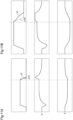
FIGS. 10A and 10B show still another example of the image that is displayed on thedisplay screen 82a of thedisplay device 82.FIGS. 10A and 10B correspond toFIGS. 8A and 8B . The example shown inFIGS. 10A and 10B illustrates a case where the driver wants to switch from turning right while reversing to turning left while reversing. In the display example shown inFIGS. 10A and 10B , the predicted trajectory Trp is significantly deviated from the target trajectory Trt. This is a state in which, due to the processes of S30 to S32, the predicted trajectory Trp does not change even when the target virtual steering angle α2* is manipulated by an input operation performed on theuser interface 80. A situation in which the predicted trajectory Trp does not change is likely to occur when the magnitude of the hitch angle β is large, as shown inFIGS. 11A and 11B . -
FIG. 11A shows a case where the target virtual steering angle α2* is turned back while the magnitude of the hitch angle β is small.FIG. 11B shows a case where the target virtual steering angle α2* is turned back while the magnitude of the hitch angle β is small. - As shown in
FIGS. 11A and 11B , when the target virtual steering angle α2* is turned back while the magnitude of the hitch angle β is large, the virtual steering angle α2 cannot follow the target virtual steering angle α2*. - If the predicted trajectory Trp does not change even though the target virtual steering angle α2* is manipulated, the driver may be confused because he or she does not know why the predicted trajectory Trp does not change. As a solution to this, in the present embodiment, the target trajectory Trt is also displayed. Accordingly, when the difference between the target trajectory Trt and the predicted trajectory Trp is large, the driver can be notified that the virtual steering angle α2 cannot be controlled to a desired angle by steering the
tractor 20. - The embodiment described above further has the following functions and effects.
- (1) The
PU 52 sets one of the axes of the coordinate system that defines the trailer coordinate components to be parallel to the front-rear direction of thetractor 20 at that time. This allows the trailer coordinate components to be easily matched with the image from thebackup camera 76. - (2) The
PU 52 performs projective transformation on the trailer coordinate components. This allows the trailer coordinate components to be appropriately matched with the image from thebackup camera 76. - (3) The
PU 32 calculates the predicted trajectory of thetrailer 30 using as an input the target steered angle α1* whose magnitude is limited to the upper limit value α1th or less. In other words, thePU 52 calculates the predicted trajectory of thetrailer 30 in the case of controlling the actual virtual steering angle α2 to as close as possible to the target virtual steering angle α2* within a range in which the magnitude of the steered angle α1 is equal to or less than the upper limit value α1th. Although the virtual steering angle α2 can be controlled by steering thetractor 20, the range of values that the virtual steering angle α2 can take is limited by the range of values that the steered angle α1 can take. Therefore, thePU 52 calculates the predicted trajectory of thetrailer 30 in the case of controlling the actual virtual steering angle α2 to as close as possible to the target virtual steering angle α2* within the range in which the magnitude of the steered angle α1 is equal to or less than the upper limit value α1th. This allows the predicted trajectory to be a feasible trajectory for thetrailer 30. - (4) The
PU 52 performs a process of displaying the target trajectory that is the trajectory of thetrailer 30 when the virtual steering angle α2 is set to the target virtual steering angle α2*. In thecombination vehicle 10, when, for example, the magnitude of the hitch angle β is relatively large, the behavior of thetrailer 30 tends to change very little no matter what value the steered angle α1 is set to. In this case, even if the driver changes the target virtual steering angle α2* to a large degree, the displayed predicted trajectory changes very little. In such a situation, the driver may be confused by the fact that the predicted trajectory does not change even though he or she changed the target virtual steering angle α2*. As a solution to this, thePU 52 also displays the target trajectory determined without considering the range of values that the steered angle α1 can take. Even in a situation where the behavior of thetrailer 30 changes very little no matter what value the steered angle α1 is set to, the target trajectory changes significantly with a change in target virtual steering angle α2*. Therefore, the predicted trajectory is deviated from the target trajectory. The driver can thus be notified that it is the situation in which the behavior of thetrailer 30 changes very little no matter what value the steered angle α1 is set to. - (5) The
PU 52 controls the virtual steering angle α2 toward the target virtual steering angle α2* by controlling the steered angle α1 toward the target steered angle α1* while keeping the magnitude of the target steering angle α1* equal to or less than the upper limit value α1th. This allows the target steered angle α1* to be set to a value that achieves the target virtual steering angle α2* as much as possible under the condition that the magnitude of the target steering angle α1* is equal to or less than the upper limit value α1th. - (6) The
PU 52 predicts a future value of the hitch angle β using the target steered angle α1* subjected to the upper limit guard process as an input. ThePU 52 performs the following three processes a plurality of times: the process of calculating the target steered angle α1* using the predicted hitch angle β as an input, the process of predicting the hitch angle β using the target steered angle α1* subjected to the upper limit guard process as an input, and the process of predicting displacement of thetrailer 30 using the predicted hitch angle β and the target steered angle α1* subjected to the upper limit guard process as inputs. There is a predetermined correlation among the virtual steering angle α2, the hitch angle β, and the steered angle α1. Therefore, when the hitch angle β changes, the target steered angle α1* that achieves the target virtual steering angle α2* changes. Accordingly, thePU 52 can accurately calculate a predicted trajectory over a relatively long time by performing the above three processes a plurality of times. - (7) The
PU 52 performs the process of assisting in steering and the process of displaying the above trajectories, both in the reverse assist mode. Reverse control of thecombination vehicle 10 requires advanced driving skills. In this regard, thePU 52 can reduce the burden of steering thetractor 20 on the driver by performing the process of assisting in steering in the reverse assist mode. Moreover, the above display process can provide information that is useful for the driver to specify the direction in which thetrailer 30 should travel. - (8) The
PU 52 continues to perform the above display process even when thecombination vehicle 10 switches from reversing to traveling forward in the reverse assist mode. When the behavior of thetrailer 30 becomes inappropriate during reverse control of thecombination vehicle 10, the driver may move thecombination vehicle 10 forward to start over the reverse control. In this case, continuing to perform the display process allows the driver to know how much thetrailer 30 needs to move forward in order to achieve the desired behavior of thetrailer 30. - (9) The
PU 52 cancels the reverse assist mode when the forward traveling speed of thecombination vehicle 10 becomes equal to or higher than the threshold Vth. When the forward traveling speed is high, it is considered that the driver does not desire reverse control and wants to move thecombination vehicle 10. Therefore, when the forward traveling speed becomes equal to or higher than the threshold Vth, thePU 52 cancels the reverse assist mode, which can save the driver the trouble of manually canceling the reverse assist mode. - (10) The
PU 52 superimposes the predicted trajectory information on the image of the outside of thecombination vehicle 10 captured by thebackup camera 76. Superimposing the predicted trajectory information on the image from thebackup camera 76 makes it easy to accurately grasp the behavior of thetrailer 30. - The above embodiment can be modified as follows. The above embodiment and the following modifications can be combined unless technical contradictions arise.
- "State Quantity Acquisition Process"
- In the process of S24, the
PU 52 acquires the hitch angle β detected by thehitch angle sensor 72. However, the present disclosure is not limited to this. For example, thePU 52 may acquire an estimated value of the hitch angle β. For example, this can be implemented by thePU 52 estimating the hitch angle β to be zero when straight traveling has continued a predetermined distance, and then sequentially updating the hitch angle β according to the amount of change Δβ given by the above equation (c2). The amount of change Δβ herein is not a predicted value of the amount of change in future hitch angle β but an estimated value of the amount of change. - - The virtual steering angle that is a variable quantifying steering of the trailer is not limited to the definition illustrated in the above embodiment. For example, the angle between the front-rear direction of the
tractor 20 and the direction of travel of the hitch point C1 may be defined as the virtual steering angle. - "Predicted Trajectory Information Calculation Process"
- The processes of S30, S32, etc. are not essential for the process of calculating the predicted trajectory of the
trailer 30 in the case of controlling the actual virtual steering angle α2 to as close as possible to the target virtual steering angle α2* within the range in which the magnitude of the steered angle α1 is equal to or less than the upper limit value α1th. The process of calculating the predicted trajectory may include a process of converting the upper limit value α1th to an upper limit value of the magnitude of the virtual steering angle α2 based on, for example, an equation obtained by inversely solving the above equation (c1). In this case, thePU 52 may perform the upper limit guard process on the target virtual steering angle α2* using the upper limit value of the magnitude of the virtual steering angle α2. ThePU 52 may then perform the processes of S34 and the subsequent steps using the value of the target virtual steered angle α1* to which the target virtual steering angle α2* subjected to the upper limit guard process is converted using the above equation (c1). - - The
PU 52 need not necessarily set the initial value of the angle θ1 to "90°" when predicting the trajectory. For example, thePU 52 may compare map data with the front-rear direction of thetractor 20, and set the angle between a predetermined axis in a coordinate system defined as desired on the map data and the front-rear direction of thetractor 20 to the initial value of the angle θ1 in the predicted trajectory information calculation process. -
- The steering process of controlling the steered angle α1 so that the virtual steering angle α2 becomes closer to the target virtual steering angle α2* is not limited to the process that is performed in the reverse assist mode. For example, the steering process may be a process of automatically steering the
tractor 20 when thecombination vehicle 10 is moving forward. -
- The above embodiment illustrates that the condition for canceling the reverse assist mode is that the logical disjunction of the conditions (A), (B) is true. However, the present disclosure is not limited to this. For example, a condition that the
combination vehicle 10 has moved forward may be used instead of the condition (B). Alternatively, for example, the cancelling condition may be the condition (A) alone. -
- The
PU 52 need not necessarily display the target trajectory Trt in addition to the predicted trajectory Trp of thetrailer 30. When displaying only the predicted trajectory Trp, thePU 52 may also display, for example, a region that is feasible as a travel trajectory of thetrailer 30. In this case, this region becomes narrow in the case where the travel path of thetrailer 30 changes very little even when the steered angle α1 is changed. Therefore, the driver can be notified that it will be difficult to change the travel trajectory of thetrailer 30 even if the virtual steering angle α2 is changed. For example, instead of displaying the above region, thePU 52 may notify the driver that it will be difficult to change the trajectory of thetrailer 30 by manipulating the target virtual steering angle α2*, when the width of the region is equal to or less than a predetermined value and the driver manipulates the target virtual steering angle α2*. This process may be a process of displaying visual information, or may be a process of giving a notification by voice. - For example, the
PU 52 may display only the predicted trajectory Trp when the difference between the predicted trajectory Trp and the target trajectory Trt is equal to or smaller than a predetermined value as in the cases illustrated inFIGS. 8A to 9B . That is, thePU 72 may sequentially determine whether the difference between the predicted trajectory Trp and the target trajectory Trt is equal to or less than the predetermined value, and need not display the target trajectory Trt when it is determined that the difference is equal to or less than the predetermined value. The difference between the predicted trajectory Trp and the target trajectory Trt being equal to or less than the predetermined value may mean that, for example, the average value of the difference between the positions on the predicted trajectory Trp and the target trajectory Trt at the same timing is equal to or less than the predetermined value. Alternatively, the difference between the predicted trajectory Trp and the target trajectory Trt being equal to or less than the predetermined value may mean that, for example, the difference between the positions on the predicted trajectory Trp and the target trajectory Trt at the same timing is not larger than the predetermined value at any position. - The predicted trajectory information to be displayed is not limited to the predicted trajectory Trp. For example, as shown in
FIGS. 12A and 12B , the predicted trajectory Trp may be provided with a margin.FIGS. 12A and 12B correspond toFIGS. 8A and 8B . InFIGS. 12A and 12B , the region determined by a pair of boundaries TrpL, TrpR of the predicted trajectory is displayed as a dotted region. The region determined by a pair of boundaries TrtL, TrtR of the target trajectory is hatched. However, these two regions may be distinguished from each other by displaying them in different colors on theactual display screen 82a. - A process of providing the predicted trajectory Trp with a margin may be implemented as follows according to whether the determination in the process of S30 is NO. When NO in the process of S30, the
PU 52 may perform the processes of S36 to S46 by "α1* + δ" and "α1* - δ" using the target steered angle α1* calculated in the process of S28. When NO in the process of S30, thePU 52 may perform the processes of S36 to S46 using, for example, the target steered angle α1* calculated by the process of S32 and a value whose absolute value is smaller than the target steered angle α1* by a predetermined amount. - A process of providing the target trajectory Trt with a margin may be a process of calculating the boundaries TrtL, TrtR as follows. In other words, this process may be a process of calculating the boundaries TrtL, TrtR by the process of S22 using "α2* + δ" and "α2* - δ" that are determined by the target virtual steering angle α2* acquired in the process of S20.
- In the case where the process of providing the predicted trajectory Trp with a margin is performed, the process of providing the target trajectory Trt with a margin need not necessarily be performed. For example, a single target trajectory may be displayed as the target trajectory Trt. In the case where the process of providing the predicted trajectory Trp with a margin is performed, the
PU 52 need not display any visual information on the target trajectory Trt. - For example, as described in the section "Steering Process," in the case where steering is automatically controlled while the
combination vehicle 10 is traveling forward, thePU 52 may superimpose the predicted trajectory Trp of thetractor 20 on an image of the area in front of thetractor 20. - The process of displaying the predicted trajectory Trp is not limited to the process in which the predicted trajectory Trp is superimposed on an image of the surroundings of the
combination vehicle 10 captured by a camera. For example, a bird's-eye view may be used as illustrated inFIGS. 13A and 13B . This allows the behavior of thetrailer 30 to be looked from a higher perspective.FIGS. 13A and 13B correspond toFIGS. 8A and 8B . This is particularly effective in the reverse assist process for thecombination vehicle 10 having apredetermined trailer 30 such as a camper. That is, when thetrailer 30 is high as shown by a long dashed short dashed line inFIG. 1 , thebackup camera 76 is not able to capture an image including the rear of thetrailer 30. - The predicted trajectory information that is superimposed on the bird's-eye view is not limited to the predicted trajectory Trp. For example, as described above, the region obtained by providing the predicted trajectory Trp with a margin may be displayed superimposed on the bird's-eye view.
- The predicted trajectory information of the
tractor 20 may also be displayed together with the predicted trajectory information of thetrailer 30. InFIGS. 14A and 14B , the predicted trajectory Trp and the target trajectory Trt are superimposed on the bird's-eye view, and a predicted trajectory Tr1L of the left end of thetractor 20 and a predicted trajectory Tr1R of the right end of thetractor 20 are also displayed.FIGS. 14A and 14B correspond toFIGS. 8A and 8B . The method for displaying the predicted trajectory of thetractor 20 is not limited to the method in which the predicted trajectory Tr1L of the left end and the predicted trajectory Tr1R of the right end are displayed. For example, a method may be used in which a single predicted trajectory, such as a predicted trajectory of the center of gravity of thetractor 20, is displayed. A region with a margin may be displayed by, for example, marking the region between the predicted trajectory Tr1L of the left end and the predicted trajectory Tr1R of the right end. - The method in which the predicted trajectory information of the
tractor 20 is displayed together with the predicted trajectory information of thetrailer 30 need not necessarily use a bird's-eye view. For example, thePU 52 may superimpose the predicted trajectory information of thetrailer 30 and the predicted trajectory information of thetractor 20 on a captured image of the outside of thecombination vehicle 10. In such a process, the target trajectory information of thetrailer 30 need not necessarily be displayed. - The predicted trajectory information of the
trailer 30 to be displayed need not necessarily be the region of the predicted trajectory Trp with a margin or the region of the predicted trajectory Trp with a margin. For example, when the direction of travel of thetrailer 30 is not straight during manual steering of thecombination vehicle 10, a right or left arrow indicating the direction of travel of thetrailer 30 may be displayed. -
- The control device is not limited to the one that includes the
PU 52 and thestorage device 54 and that performs software processing. For example, the control device may include a dedicated hardware circuit, such as an ASIC, that performs, by hardware processing, at least part of the various processes performed in the above embodiment. That is, the control device can be any control device as long as it has one of the following configurations (a) to (c): (a) a processing circuit including a processing device that performs all of the above processes according to a program, and a program storage device such as a storage device that stores the program, (b) a processing circuit including a processing device that performs part of the above processes according to a program, a program storage device, and a dedicated hardware circuit that performs the remainder of the above processes, and (c) a processing circuit including a dedicated hardware circuit that performs all of the above processes. There may be a plurality of software execution devices including a processing device and a program storage device, and a plurality of dedicated hardware circuits. -
- The computer that executes a control program such as the reverse assist
program 54a is not limited to the computer installed in thecombination vehicle 10. For example, the computer may be configured by both thePU 52 installed in thecombination vehicle 10 and a mobile terminal of the driver. In this case, for example, the mobile terminal may perform the processes of S28 to S32 and S36 to S50. -
- The combination vehicle is not limited to the vehicle illustrated in
FIG. 1 .
Claims (12)
- A control device for a combination vehicle including a tractor and a trailer that is towed by the tractor, the control device being configured to perform a state quantity acquisition process, a predicted trajectory information calculation process, and a display process, wherein:the state quantity acquisition process is a process of acquiring a state quantity of the combination vehicle;the predicted trajectory information calculation process is a process of calculating predicted trajectory information of the trailer according to the state quantity; andthe display process is a process of displaying the predicted trajectory information by operating a display device.
- The control device for the combination vehicle according to claim 1, wherein:the combination vehicle includes an interface for a driver to specify a target virtual steering angle;the target virtual steering angle is a target value of a virtual steering angle;the virtual steering angle is a variable indicating a direction of travel at a connection point between the tractor and the trailer;the control device is configured to perform a target virtual steering angle acquisition process and a steering process;the target virtual steering angle acquisition process is a process of acquiring the target virtual steering angle according to an input operation that is performed on the interface by the driver;the predicted trajectory information calculation process is a process of, by using the virtual steering angle as an input, calculating a predicted trajectory of the trailer in a case of controlling an actual virtual steering angle to as close as possible to the target virtual steering angle within a range in which a magnitude of a steered angle of the tractor is equal to or less than an upper limit value;the display process is a process of displaying the predicted trajectory; andthe steering process is a process of controlling the steered angle of the tractor so as to control the virtual steering angle toward the target virtual steering angle.
- The control device for the combination vehicle according to claim 2, wherein:the control device is configured to perform a target trajectory calculation process;the target trajectory calculation process is a process of calculating a target trajectory that is a trajectory of the trailer when the target virtual steering angle is used as an input and the virtual steering angle is set to the target virtual steering angle; andthe display process includes a process of displaying the target trajectory in addition to the predicted trajectory.
- The control device for the combination vehicle according to claim 2, wherein:the state quantity acquisition process includes a process of acquiring a hitch angle;the hitch angle is an angle between a front-rear direction of the tractor and a front-rear direction of the trailer;the predicted trajectory information calculation process includes a target steered angle calculation process, an upper limit guard process, and a displacement prediction process;the target steered angle calculation process includes a process of calculating a target steered angle that is a target value of the steered angle of the tractor, by using the target virtual steering angle and the hitch angle as inputs;the upper limit guard process is a process of setting a magnitude of the target steered angle to the upper limit value when the magnitude of the target steered angle is larger than the upper limit value;the displacement prediction process includes a process of predicting a displacement of the trailer using the target steered angle subjected to the upper limit guard process as an input; andthe steering process includes a process of controlling the virtual steering angle toward the target virtual steering angle by controlling the steered angle toward the target steered angle.
- The control device for the combination vehicle according to claim 4, wherein:the control device is configured to perform a hitch angle prediction process;the hitch angle prediction process is a process of predicting a future value of the hitch angle using the target steered angle subjected to the upper limit guard process as an input; andthe control device is configured to perform the following three processes a plurality of times: the target steered angle calculation process that uses the predicted hitch angle as an input; the hitch angle prediction process that uses the target steered angle subjected to the upper limit guard process as an input; and the displacement prediction process that uses the predicted hitch angle and the target steered angle subjected to the upper limit guard process as inputs.
- The control device for the combination vehicle according to claim 2, wherein:the control device is configured to perform a determination process;the determination process is a process of determining whether a reverse assist mode is selected;the reverse assist mode is a process of implementing a process of reversing the combination vehicle by the steering process; andthe display process is configured to be performed in the reverse assist mode.
- The control device for the combination vehicle according to claim 6, wherein the display process is configured to be continued even when the combination vehicle switches from reversing to traveling forward in the reverse assist mode.
- The control device for the combination vehicle according to claim 7, wherein:the control device is configured to perform a cancellation process; andthe cancellation process is a process of canceling the reverse assist mode when a forward traveling speed of the combination vehicle becomes equal to or higher than a threshold.
- The control device for the combination vehicle according to claim 1, wherein the display process includes a process of superimposing the predicted trajectory information on an image of an outside of the combination vehicle captured by a camera.
- The control device for the combination vehicle according to claim 1, wherein the display process includes a process of superimposing the predicted trajectory information on a bird's-eye view of an area around the combination vehicle.
- A control method for a combination vehicle including a tractor and a trailer that is towed by the tractor, the control method comprising performing a state quantity acquisition process, a predicted trajectory information calculation process, and a display process, wherein:the state quantity acquisition process is a process of acquiring a state quantity of the combination vehicle;the predicted trajectory information calculation process is a process of calculating predicted trajectory information of the trailer according to the state quantity; andthe display process is a process of displaying the predicted trajectory information by operating a display device.
- A control program for a combination vehicle including a tractor and a trailer that is towed by the tractor, the control program being a program that causes a computer to perform a state quantity acquisition process, a predicted trajectory information calculation process, and a display process, wherein:the state quantity acquisition process is a process of acquiring a state quantity of the combination vehicle;the predicted trajectory information calculation process is a process of calculating predicted trajectory information of the trailer according to the state quantity; andthe display process is a process of displaying the predicted trajectory information by operating a display device.
Applications Claiming Priority (2)
| Application Number | Priority Date | Filing Date | Title |
|---|---|---|---|
| JP2022084039A JP7827542B2 (en) | 2022-05-23 | 2022-05-23 | Control device for articulated vehicles, control method for articulated vehicles, and control program for articulated vehicles |
| PCT/JP2023/018563 WO2023228854A1 (en) | 2022-05-23 | 2023-05-18 | Coupled vehicle control device, coupled vehicle control method, and coupled vehicle control program |
Publications (2)
| Publication Number | Publication Date |
|---|---|
| EP4530160A1 true EP4530160A1 (en) | 2025-04-02 |
| EP4530160A4 EP4530160A4 (en) | 2025-08-27 |
Family
ID=88919246
Family Applications (1)
| Application Number | Title | Priority Date | Filing Date |
|---|---|---|---|
| EP23811727.9A Pending EP4530160A4 (en) | 2022-05-23 | 2023-05-18 | Coupled vehicle control device, coupled vehicle control method and coupled vehicle control program |
Country Status (5)
| Country | Link |
|---|---|
| US (1) | US20250313264A1 (en) |
| EP (1) | EP4530160A4 (en) |
| JP (1) | JP7827542B2 (en) |
| CN (1) | CN119233924A (en) |
| WO (1) | WO2023228854A1 (en) |
Families Citing this family (3)
| Publication number | Priority date | Publication date | Assignee | Title |
|---|---|---|---|---|
| US20250115295A1 (en) * | 2023-10-06 | 2025-04-10 | Panasonic Automotive Systems Company Of America, Division Of Panasonic Corporation Of North America | Method of correctly predicting trailer trajectory while reversing |
| US20260021766A1 (en) * | 2024-07-17 | 2026-01-22 | Stoneridge Electronics Ab | Camera monitor system trailer backup trajectory overlay with vehicle speed-based correction |
| JP2026054071A (en) * | 2024-09-13 | 2026-03-26 | 株式会社ジェイテクト | Control device for coupled vehicles, method for controlling coupled vehicles, and control program for coupled vehicles |
Family Cites Families (7)
| Publication number | Priority date | Publication date | Assignee | Title |
|---|---|---|---|---|
| JP2009060499A (en) | 2007-09-03 | 2009-03-19 | Sanyo Electric Co Ltd | Driving support system, and combination vehicle |
| US9506774B2 (en) * | 2011-04-19 | 2016-11-29 | Ford Global Technologies, Llc | Method of inputting a path for a vehicle and trailer |
| US10112646B2 (en) | 2016-05-05 | 2018-10-30 | Ford Global Technologies, Llc | Turn recovery human machine interface for trailer backup assist |
| CN106915304A (en) * | 2017-02-27 | 2017-07-04 | 北京新能源汽车股份有限公司 | Vehicle control method, control device, vehicle control system and automobile |
| WO2021127693A1 (en) * | 2019-12-16 | 2021-06-24 | Magna Electronics Inc. | Vehicular trailering guidance system |
| JP7460371B2 (en) | 2020-01-06 | 2024-04-02 | フォルシアクラリオン・エレクトロニクス株式会社 | Traction Assistance Device |
| US11577782B2 (en) | 2020-03-10 | 2023-02-14 | GM Global Technology Operations LLC | Method and apparatus for an automated trailer backup system in a motor vehicle |
-
2022
- 2022-05-23 JP JP2022084039A patent/JP7827542B2/en active Active
-
2023
- 2023-05-18 US US18/865,445 patent/US20250313264A1/en active Pending
- 2023-05-18 WO PCT/JP2023/018563 patent/WO2023228854A1/en not_active Ceased
- 2023-05-18 CN CN202380040513.2A patent/CN119233924A/en active Pending
- 2023-05-18 EP EP23811727.9A patent/EP4530160A4/en active Pending
Also Published As
| Publication number | Publication date |
|---|---|
| EP4530160A4 (en) | 2025-08-27 |
| US20250313264A1 (en) | 2025-10-09 |
| JP2023172329A (en) | 2023-12-06 |
| WO2023228854A1 (en) | 2023-11-30 |
| CN119233924A (en) | 2024-12-31 |
| JP7827542B2 (en) | 2026-03-10 |
Similar Documents
| Publication | Publication Date | Title |
|---|---|---|
| US20250313264A1 (en) | Control device for combination vehicle, control method for combination vehicle, and control program for combination vehicle | |
| JP6704062B2 (en) | Vehicle control device | |
| EP2988983B1 (en) | System for a towing vehicle | |
| US9902425B2 (en) | System for guiding trailer along target route during reversing maneuver | |
| EP4049916B1 (en) | Vehicle control method, vehicle control system, and vehicle | |
| CN109844669B (en) | Vehicle control device | |
| US10632919B2 (en) | Vehicle hitch assist system | |
| EP3915857B1 (en) | A parking assist apparatus and a method of controlling the parking assist apparatus | |
| US11279405B2 (en) | Hitch assist system | |
| CN113386783B (en) | Method and apparatus for an automatic trailer reversing system in a motor vehicle | |
| EP2546122A1 (en) | Steering support device | |
| US20120277955A1 (en) | Driving assistance device | |
| US20130173148A1 (en) | Parking assistance apparatus | |
| US10543870B1 (en) | Hitch assist system | |
| CN110722939A (en) | Hitching auxiliary system | |
| EP3290302A1 (en) | Parking exit assist device | |
| CN114852063A (en) | Active HMI guidance for assisting rollback from impending trailer side contact | |
| JP7189836B2 (en) | Vehicle coupling assistance device, vehicle coupling assistance method, vehicle coupling assistance system, and steering control device | |
| JP2001088723A (en) | Vehicle steering system | |
| JP7496448B2 (en) | MOBILE BODY CONTROL DEVICE, MOBILE BODY, AND MOBILE BODY CONTROL METHOD | |
| US20250196877A1 (en) | Control device, control method, and storage medium storing control program | |
| EP4527719A1 (en) | Control device for coupled vehicle, control method for coupled vehicle, and control program for coupled vehicle | |
| US20240409084A1 (en) | Jackknifing suppression device, jackknifing suppression method, and non-transitory computer-readable medium | |
| JP7255699B2 (en) | Vehicle operation switching device, vehicle operation system, vehicle operation switching method | |
| EP4640524A1 (en) | Computation device for articulated vehicle, control device for articulated vehicle, computation method for articulated vehicle, and computation program for articulated vehicle |
Legal Events
| Date | Code | Title | Description |
|---|---|---|---|
| STAA | Information on the status of an ep patent application or granted ep patent |
Free format text: STATUS: THE INTERNATIONAL PUBLICATION HAS BEEN MADE |
|
| PUAI | Public reference made under article 153(3) epc to a published international application that has entered the european phase |
Free format text: ORIGINAL CODE: 0009012 |
|
| STAA | Information on the status of an ep patent application or granted ep patent |
Free format text: STATUS: REQUEST FOR EXAMINATION WAS MADE |
|
| 17P | Request for examination filed |
Effective date: 20241203 |
|
| AK | Designated contracting states |
Kind code of ref document: A1 Designated state(s): AL AT BE BG CH CY CZ DE DK EE ES FI FR GB GR HR HU IE IS IT LI LT LU LV MC ME MK MT NL NO PL PT RO RS SE SI SK SM TR |
|
| A4 | Supplementary search report drawn up and despatched |
Effective date: 20250725 |
|
| DAV | Request for validation of the european patent (deleted) | ||
| DAX | Request for extension of the european patent (deleted) | ||
| RIC1 | Information provided on ipc code assigned before grant |
Ipc: B62D 6/00 20060101AFI20250721BHEP Ipc: B62D 13/06 20060101ALI20250721BHEP Ipc: B62D 15/02 20060101ALI20250721BHEP Ipc: B62D 101/00 20060101ALI20250721BHEP Ipc: B62D 113/00 20060101ALI20250721BHEP Ipc: B62D 115/00 20060101ALI20250721BHEP Ipc: B60D 1/24 20060101ALI20250721BHEP Ipc: B60R 1/00 20220101ALI20250721BHEP Ipc: B60D 1/62 20060101ALI20250721BHEP |