EP4530151A1 - Zugkuppell - Google Patents
Zugkuppell Download PDFInfo
- Publication number
- EP4530151A1 EP4530151A1 EP24202497.4A EP24202497A EP4530151A1 EP 4530151 A1 EP4530151 A1 EP 4530151A1 EP 24202497 A EP24202497 A EP 24202497A EP 4530151 A1 EP4530151 A1 EP 4530151A1
- Authority
- EP
- European Patent Office
- Prior art keywords
- coupling
- coupling head
- guide
- train
- plug pin
- Prior art date
- Legal status (The legal status is an assumption and is not a legal conclusion. Google has not performed a legal analysis and makes no representation as to the accuracy of the status listed.)
- Pending
Links
Images


Classifications
-
- B—PERFORMING OPERATIONS; TRANSPORTING
- B61—RAILWAYS
- B61G—COUPLINGS; DRAUGHT AND BUFFING APPLIANCES
- B61G5/00—Couplings for special purposes not otherwise provided for
- B61G5/04—Couplings for special purposes not otherwise provided for for matching couplings of different types, i.e. transitional couplings
-
- B—PERFORMING OPERATIONS; TRANSPORTING
- B61—RAILWAYS
- B61G—COUPLINGS; DRAUGHT AND BUFFING APPLIANCES
- B61G3/00—Couplings comprising mating parts of similar shape or form which can be coupled without the use of any additional element or elements
- B61G3/16—Couplings comprising mating parts of similar shape or form which can be coupled without the use of any additional element or elements with coupling heads rigidly connected by rotatable hook plates or discs and balancing links, the coupling members forming a parallelogram, e.g. "Scharfenberg" type
-
- B—PERFORMING OPERATIONS; TRANSPORTING
- B61—RAILWAYS
- B61G—COUPLINGS; DRAUGHT AND BUFFING APPLIANCES
- B61G7/00—Details or accessories
Definitions
- the present invention relates to a train coupling with a coupling head which is pivotably mounted about a horizontal pivot axis in a coupling head receptacle, for example at the end of a drawbar.
- a generic train coupling is used, for example, in WO 2021/185497 A1
- This comprises a coupling head of an automatic coupling, which can be pivoted into a horizontal coupling plane as required.
- a second coupling device in the form of a drawbar eye is provided, which can be pivoted into the coupling plane when the coupling head has been pivoted from an active position in the coupling plane to an inactive position outside the coupling plane.
- an actuating device which is attached to a drawbar, to the end of which the coupling head is pivotably connected, and comprises a drive device which, eccentrically to a horizontal joint axis about which the coupling head is pivotable, engages a joint arrangement via which the coupling head is pivotably mounted about the horizontal joint axis.
- the drive device is designed, for example, as a hydraulic or pneumatic linear motor and holds the coupling head in its active position in the coupling plane.
- Another drawbar coupling with drawbar eye and automatic drawbar coupling which can be swivelled into a horizontal plane to serve as a coupling, is installed in EP 3 590 784 A1
- the automatic drawbar coupling comprises a coupling head that is detachably attached to a drawbar for easy replacement. The attachment can be achieved via a clamp sleeve arrangement or via locking pins.
- a disadvantage of the known train couplings is that the alignment of the coupling head in its active position in the horizontal plane is subject to tolerances, so that, especially if the coupling head is used as automatic coupling head, problems may occur when coupling with an opposite coupling head, which require manual adjustment.
- the object of the present invention is to provide a train coupling with a coupling head of the type shown, with which it is possible to lock the coupling head precisely and reliably in its active position against pivoting of the coupling head about the pivot axis.
- a train coupling according to the invention has a coupling head that is pivotably mounted about a horizontal pivot axis in a coupling head receptacle, wherein the coupling head is pivotable about the horizontal pivot axis between an active position, in which it is aligned for coupling with an oppositely identical coupling head within a horizontal plane, and an inactive position, in which it is pivoted out of the horizontal plane.
- a locking device is provided with which the coupling head can be locked in the horizontal plane. The locking device therefore blocks pivoting of the coupling head about the horizontal pivot axis. When the locking device is released, it releases this pivoting of the coupling head from the active position within the horizontal plane to the inactive position outside the horizontal plane, for example pivoting downwards and/or preferably upwards.
- the locking device comprises a plug-in pin which can be inserted through a first guide in the coupling head and a second guide in the coupling head receptacle in order to form-fit the coupling head to prevent rotation about the pivot axis.
- the locking pin when the locking pin is inserted through the first guide and the second guide, it locks the coupling head against pivoting about the pivot axis, so that the coupling head remains precisely aligned in the desired active position in the horizontal plane.
- the locking pin is removed from at least one of the two guides, in particular from both guides, it allows the coupling head to pivot about the pivot axis, so that the coupling head can be pivoted about the pivot axis from the active position to the inactive position.
- the plug pin locks the coupling head in its active position in a form-fitting manner directly in the area of the coupling head receptacle, it can be ensured that the coupling head is always aligned exactly within the horizontal plane when it has been pivoted into its active position.
- the coupling head is permanently connected to the coupling head receptacle.
- the entire coupling head or parts of the coupling head can be removed from the coupling head receptacle so that the coupling head or the coupling parts can be replaced.
- the actual coupling device(s) can be removed from the remaining part of the coupling head to be replaced with similar or different coupling devices.
- the coupling head receptacle has a first stop against which the coupling head strikes when pivoting into the active position.
- the stop is arranged such that the first guide and the second guide are aligned with each other. This facilitates the insertion of the plug pin into the first guide and the second guide.
- the plug pin when inserted into the first guide and the second guide, is rotatable about its longitudinal axis within the first and second guides and has at least one radial projection that can be rotated with the plug pin to form an undercut with a stop surface on the coupling head receptacle in order to block withdrawal of the plug pin from the first and second guides. This prevents accidental withdrawal of the plug pin from the first and second guides.
- the radial projection is designed as a lever extending perpendicularly or at an angle to the longitudinal axis. This facilitates its rotation behind the stop surface.
- the stop surface extends below the longitudinal axis in the active position of the coupling head. This means that the radial projection only needs to be rotated downwards, either actively or under its own weight, to form the undercut with the stop surface.
- the locking pin can be rotated in the inserted state upon application of a torque
- the radial projection which is designed, for example, as a cylindrical lever, has a length and a weight that, when the locking pin is inserted, exerts a drive torque on the locking pin about its longitudinal axis, wherein the drive torque is greater than the torque.
- the locking pin automatically rotates with the radial projection behind the stop surface on the coupling head receptacle to form the undercut.
- the plug pin is preferably kept at least substantially free from any clamping force in the inserted state, which could be generated, for example, by the weight of the coupling head.
- This can be achieved by appropriately positioning the first stop in the A coupling head receptacle can be achieved, which in particular absorbs the entire weight force or the torque generated by the weight force of the coupling head, which acts to rotate the coupling head downwards about the pivot axis. Accordingly, several such first stops can also be provided.
- the locking pin can only be inserted into the first and second guides in one rotational position about the longitudinal axis, in which the radial projection is arranged with a rotation angle of less than 180°, in particular less than 135° or 90°, relative to the stop surface and is also arranged opposite a vertical plane on the side of the stop surface. This ensures that the desired drive torque acts on the locking pin due to the weight force to move the radial projection behind the stop surface.
- the coupling head receptacle comprises a fork shape with two forks between which the coupling head is received.
- Each fork can then have a bore, with the two bores together forming the second guide.
- the first guide is preferably formed by a step in a radially outer surface of a housing of the coupling head.
- At least one pressure piece is provided in the step, which limits the contact surface of the plug pin in one or both directions of rotation of the coupling head around the pivot axis to less than two-thirds or less than half of the mutual distance between the forks in the area of the plug pin. This limits the friction surface between the plug pin and the coupling head, which facilitates the rotation of the plug pin in the inserted state.
- the at least one pressure piece preferably has a friction-reduced surface, at least in comparison to the surface of the coupling head arranged next to it.
- the coupling head receptacle is preferably formed by an axial end of a drawbar.
- the coupling head is in particular an automatic train coupling.
- the coupling head comprises a first coupling device of a first type, in particular with a coupling projection and coupling opening, for example with a coupling cone and coupling funnel
- the towing coupling further comprises a second coupling device of a second type, different from the first type, in particular with a towing eye or towing hook.
- the second coupling device is then preferably alignable or aligned within the horizontal plane in the inactive position of the coupling head.
- the coupling head with coupling projection and coupling opening is designed in particular as a coupling head of a Scharfenberg coupling, preferably with a frog.
- the second coupling device can only be pivoted into the horizontal plane when the coupling head is in its inactive position.
- a coupling head 1 of a train coupling is shown, which is mounted in a coupling head receptacle 3 about a horizontal pivot axis 2.
- the coupling head receptacle 3 is provided at the axial end of a drawbar 16, which is connected with its other axial end in a horizontally pivotable manner, for example, to a car body 19.
- the pull rod 16 has a longitudinal axis 20 which, together with the pivot axis 2, forms a horizontal plane in which the Figure 1 shown active position of the coupling head 1 and which can also be referred to as the coupling plane.
- the coupling head receptacle 3 has a fork shape with two forks 11, 12, between which the coupling head 1 is received.
- Each fork 11, 12 comprises a bore 7.1, 7.2, which together form a second guide 7.
- the radially outer surface of one Housing 14 of the coupling head 1 forms a first guide 6.
- the locking device 4 comprises a plug pin 5, which is inserted into the first guide 6 in the coupling head 1 and the second guide 7 in the coupling head receptacle 3, whereby the coupling head 1 is positively secured against rotation about the pivot axis 2 in the horizontal plane, i.e. in its active position.
- the plug pin 5 has a longitudinal axis 8 about which it can be rotated when inserted into the first guide 6 and the second guide 7.
- the plug pin 5 also has a radial projection 9, here in the form of a lever, which, when the plug pin 5 is inserted into the first guide 6 and the second guide 7, can be rotated behind a stop surface 10 on the coupling head receptacle in order to positively block withdrawal of the plug pin 5 from the first guide 6 and the second guide 7.
- the first guide 6 in the coupling head 1 preferably has one or more pressure pieces 15, which comparatively reduce the contact area between the coupling head 1, here its housing 14, and the plug pin 5.
- the pressure piece(s) 15 can furthermore have a friction-reducing surface.
- the first guide 6 is formed by a step 13 in the radially outer surface of the housing 14, and thrust pieces 15 are inserted into this step 13, which ensure that the plug pin 5 bears against the pivot axis 2 in both directions of rotation of the coupling head 1.
- the contact surface is reduced to less than half the width of the housing 14 between the forks 11, 12, relative to each pivot direction.
- the coupling head 1 has a first coupling device 17 in the form of a Scharfenberg coupling with a coupling cone 17.1 and coupling funnel 17.2.
- the towing coupling further has a second coupling device 18 with a towing eye 18.1.
- Such a towing eye 18.1 can establish a towing connection with a towing hook.
- the second coupling device 18 can in particular only be pivoted into the horizontal plane, i.e. the coupling plane, about the pivot axis 2 when the coupling head 1 is in its Figure 3 shown inactive position.
- the pivoting of the second coupling device 18 is positively coupled to the pivoting of the coupling head 1, so that the coupling head 1 and the second coupling device 18 are always pivoted together about the pivot axis 2.
- a separate pivoting of the coupling head 1 and the second coupling device 18 about the pivot axis 2 can also be provided.
- a drive 21 is provided, which according to the embodiment in the Figures 1 to 3 is designed as a hand crank and according to the embodiment in the Figure 4 as an electric, pneumatic or hydraulic drive.
- the coupling head 1 can also be pivoted without a separate gear, for example by hand, by applying a corresponding manual force to the coupling head 1.
- the coupling head receptacle 3 has a first stop 22, against which the coupling head 1, here with a coupling head stop 23, strikes when it is pivoted from its inactive position to its active position and reaches the active position In this position, the Figure 4 visible first and second guides 6, 7, and the plug pin 5 can be easily inserted into these guides 6, 7 with very little play. Accordingly, the coupling head 1 is held exactly in the horizontal plane when the plug pin 5 is inserted.
- the coupling head receptacle 3 has a second stop 24, against which the coupling head 1, here with its coupling head stop 23, strikes when the coupling head 1 is rotated into its inactive position.
- a corresponding locking device for example, with a locking pin, could be provided here to positively hold the coupling head 1 in the inactive position.
- the first stop 22 could also additionally or alternatively be provided at the rear, that is to say on the rear side of the coupling head 1 facing the coupling head receptacle 3 or the pull rod 16, and/or at the bottom of the coupling head receptacle 3 or the pull rod 16, in particular as a counter surface to a coupling head stop 23 in the form of a nose or projection on the coupling head 1 protruding from the radially outer surface of the housing 14, wherein the coupling head stop 23 on the coupling head 1 then strikes the first stop 22 from below and/or from the front when the coupling head 1 is in its active position.
- first stop 22 and the coupling head stop 23 can preferably be provided at least substantially centrally between the forks 11, 12, while in the illustrated embodiment, both forks 11, 12 are preferably each provided with a first stop 22, against which a coupling head stop 23 abuts in order to evenly absorb the weight of the coupling head 1.
- first stops 22 jamming forces between the plug pin 5 and the first and second guides 6, 7 can be avoided.
Landscapes
- Engineering & Computer Science (AREA)
- Mechanical Engineering (AREA)
- Details Of Connecting Devices For Male And Female Coupling (AREA)
Abstract
Die Erfindung betrifft eine Zugkupplung mit einem Kupplungskopf, der verschwenkbar um eine horizontale Verschwenkachse in einer Kupplungskopfaufnahme gelagert ist, wobei der Kupplungskopf zwischen einer aktiven Position, in welcher er zum Kuppeln mit einem gegengleichen Kupplungskopf innerhalb einer Horizontalebene ausgerichtet ist, und einer inaktiven Position, in welcher er aus der Horizontalebene heraus verschwenkt ist, um die horizontale Verschwenkachse verschwenkbar ist; wobei
eine Arretiervorrichtung vorgesehen ist, mit welcher der Kupplungskopf in der Horizontalebene arretierbar ist.
eine Arretiervorrichtung vorgesehen ist, mit welcher der Kupplungskopf in der Horizontalebene arretierbar ist.
Die erfindungsgemäß Zugkupplung ist dadurch gekennzeichnet, dass die Arretiervorrichtung einen Steckbolzen umfasst, der durch eine erste Führung im Kupplungskopf und eine zweite Führung in der Kupplungskopfaufnahme steckbar ist, um den Kupplungskopf formschlüssig gegen Verdrehen um die Verschwenkachse zu sichern.
Description
- Die vorliegende Erfindung betrifft eine Zugkupplung mit einem Kupplungskopf, der verschwenkbar um eine horizontale Verschwenkachse in einer Kupplungskopfaufnahme, beispielsweise am Ende einer Zugstange, gelagert ist.
- Eine gattungsgemäße Zugkupplung wird beispielsweise in
WO 2021/185497 A1 offenbart. Diese umfasst einen Kupplungskopf einer automatischen Kupplung, der bedarfsweise in eine Kupplungsebene, die horizontal ist, verschwenkt werden kann. Ferner ist eine zweite Kupplungseinrichtung in Form einer Zugöse vorgesehen, die dann in die Kupplungsebene verschwenkbar ist, wenn der Kupplungskopf aus einer aktiven Position in der Kupplungsebene in eine inaktive Position außerhalb der Kupplungsebene verschwenkt wurde. Zum Verschwenken des Kupplungskopfes ist eine Betätigungsvorrichtung vorgesehen, die an einer Zugstange, an deren Ende der Kupplungskopf verschwenkbar angeschlossen ist, befestigt ist und eine Antriebseinrichtung umfasst, die exzentrisch zu einer horizontalen Gelenkachse, um welche der Kupplungskopf verschwenkbar ist, an eine Gelenkanordnung angreift, über welche der Kupplungskopf um die horizontale Gelenkachse schwenkbar gelagert ist. Die Antriebseinrichtung ist beispielsweise als hydraulischer oder pneumatischer Linearmotor ausgebildet und hält den Kupplungskopf in seiner aktiven Position in der Kupplungsebene. - Eine weitere Zugkupplung mit Zugöse und automatischer Zugkupplung, die wahlweise in eine Horizontalebene verschwenkt werden können, um dort als Kupplung zu dienen, wird in
EP 3 590 784 A1 offenbart. Die automatische Zugkupplung weist einen Kupplungskopf auf, der zu seiner Auswechslung lösbar an einer Zugstange befestigt ist. Die Befestigung kann über eine Schalenmuffenanordnung oder über Steckbolzen hergestellt werden. - Nachteilig an den bekannten Zugkupplungen ist, dass die Ausrichtung des Kupplungskopfes in seiner aktiven Position in der Horizontalebene toleranzbehaftet ist, sodass, insbesondere wenn der Kupplungskopf als automatischer Kupplungskopf ausgeführt ist, Probleme beim Kuppeln mit einem gegengleichen Kupplungskopf auftreten können, die ein manuelles Nachstellen erfordern.
- Der vorliegenden Erfindung liegt die Aufgabe zugrunde, eine Zugkupplung mit einem Kupplungskopf der dargestellten Art anzugeben, mit welcher eine Arretierung des Kupplungskopfes gegen ein Verschwenken des Kupplungskopfes um die Verschwenkachse in seiner aktiven Position präzise und zuverlässig möglich ist.
- Die erfindungsgemäße Aufgabe wird durch eine Zugkupplung mit den Merkmalen von Anspruch 1 gelöst. Die abhängigen Ansprüche beschreiben vorteilhafte und besonders zweckmäßige Ausgestaltungen der Erfindung.
- Eine erfindungsgemäße Zugkupplung weist einen Kupplungskopf auf, der verschwenkbar um eine horizontale Verschwenkachse in einer Kupplungskopfaufnahme gelagert ist, wobei der Kupplungskopf zwischen einer aktiven Position, in welcher er zum Kuppeln mit einem gegengleichen Kupplungskopf innerhalb einer Horizontalebene ausgerichtet ist, und einer inaktiven Position, in welcher er aus der Horizontalebene heraus verschwenkt ist, um die horizontale Verschwenkachse verschwenkbar ist. Ferner ist eine Arretiervorrichtung vorgesehen, mit welcher der Kupplungskopf in der Horizontalebene arretierbar ist. Die Arretiervorrichtung blockiert demnach ein Verschwenken des Kupplungskopfes um die horizontale Verschwenkachse. Wenn die Arretiervorrichtung gelöst wird, gibt sie dieses Verschwenken des Kupplungskopfes aus der aktiven Position innerhalb der Horizontalebene in die inaktive Position außerhalb der Horizontalebene frei, beispielsweise ein Verschwenken nach unten und/oder bevorzugt nach oben.
- Erfindungsgemäß umfasst die Arretiervorrichtung einen Steckbolzen, der durch eine erste Führung im Kupplungskopf und eine zweite Führung in der Kupplungskopfaufnahme steckbar ist, um den Kupplungskopf formschlüssig gegen Verdrehen um die Verschwenkachse zu sichern. Wenn somit der Steckbolzen durch die erste Führung und die zweite Führung gesteckt ist, verriegelt er den Kupplungskopf gegen ein Verschwenken um die Verschwenkachse, sodass der Kupplungskopf exakt in der gewünschten aktiven Position in der Horizontalebene ausgerichtet bleibt. Wenn hingegen der Steckbolzen aus wenigstens einer der beiden Führungen, insbesondere aus beiden Führungen, herausgezogen wird, so gibt er das Verschwenken des Kupplungskopfes um die Verschwenkachse frei, sodass der Kupplungskopf um die Verschwenkachse aus der aktiven Position in die inaktive Position verschwenkt werden kann.
- Da erfindungsgemäß der Steckbolzen den Kupplungskopf in seiner aktiven Position formschlüssig unmittelbar im Bereich der Kupplungskopfaufnahme gegen diese arretiert, kann sichergestellt werden, dass der Kupplungskopf stets exakt innerhalb der Horizontalebene ausgerichtet ist, wenn er in seine aktive Position verschwenkt wurde.
- Der Kupplungskopf ist gemäß einer Ausführungsform unlösbar an der Kupplungskopfaufnahme angeschlossen. Gemäß einer alternativen Ausführungsform kann der gesamte Kupplungskopf oder Teile des Kupplungskopfes können von der Kupplungskopfaufnahme abgenommen werden, damit der Kupplungskopf beziehungsweise die Kupplungsteile ausgetauscht werden können. Beispielsweise können der oder die eigentlichen Kuppeleinrichtungen vom verbleibenden Teil des Kupplungskopfes abgenommen werden, um durch gleichartige oder andersartige Kupplungseinrichtungen ersetzt zu werden.
- Bevorzugt weist die Kupplungskopfaufnahme einen ersten Anschlag auf, an welchem der Kupplungskopf beim Verschwenken in die aktive Position anschlägt, wobei der Anschlag derart angeordnet ist, dass die erste Führung und die zweite Führung miteinander fluchten. Damit wird das Einstecken des Steckbolzens in die erste Führung und die zweite Führung erleichtert.
- Bevorzugt ist der Steckbolzen im in die erste Führung und die zweite Führung eingesteckten Zustand innerhalb der ersten und zweiten Führung um seine Längsachse verdrehbar und weist wenigstens einen Radialvorsprung auf, der zur Ausbildung eines Hinterschnitts mit einer Anschlagfläche an der Kupplungskopfaufnahme mit dem Steckbolzen verdrehbar ist, um ein Herausziehen des Steckbolzens aus der ersten und der zweiten Führung zu blockieren. Damit kann ein versehentliches Herausziehen des Steckbolzens aus der ersten Führung und der zweiten Führung vermieden werden.
- Bevorzugt ist der Radialvorsprung als senkrecht oder winklig zur Längsachse verlaufender Hebel ausgeführt. Dadurch wird sein Verdrehen hinter die Anschlagfläche erleichtert.
- Besonders bevorzugt erstreckt sich die Anschlagfläche in der aktiven Position des Kupplungskopfes unterhalb der Längsachse. Damit muss der Radialvorsprung nur aktiv oder durch Eigengewicht nach unten verdreht werden, um den Hinterschnitt mit der Anschlagfläche auszubilden.
- Besonders bevorzugt ist der Steckbolzen im eingesteckten Zustand unter Aufbringung eines Drehmoments verdrehbar und der Radialvorsprung, der beispielsweise als zylindrischer Hebel ausgeführt ist, weist eine Länge und ein Gewicht auf, die im eingesetzten Zustand des Steckbolzens ein Antriebsmoment um die Längsachse auf den Steckbolzen ausüben, wobei das Antriebsmoment größer als das Drehmoment ist. Damit verdreht sich der Steckbolzen automatisch im eingesteckten Zustand mit dem Radialvorsprung zur Ausbildung des Hinterschnitts hinter die Anschlagfläche an der Kupplungskopfaufnahme.
- Damit ein leichtes Verdrehen des Steckbolzens im eingesteckten Zustand begünstigt wird, wird der Steckbolzen bevorzugt im eingesteckten Zustand zumindest im Wesentlichen frei von einer Verklemmkraft gehalten, die beispielsweise durch die Gewichtskraft des Kupplungskopfes erzeugt werden könnte. Dies kann durch geeignete Positionierung des ersten Anschlags in der Kupplungskopfaufnahme erreicht werden, über den insbesondere die gesamte Gewichtskraft beziehungsweise das durch die Gewichtskraft des Kupplungskopfes erzeugte Drehmoment, welches im Sinne eines nach unten Verdrehens des Kupplungskopfes um die Verschwenkachse wirkt, aufgenommen wird. Es können entsprechend auch mehrere solche ersten Anschläge vorgesehen sein.
- Günstig ist, wenn der Steckbolzen nur in einer Drehposition um die Längsachse in die erste und zweite Führung einsteckbar ist, in welcher der Radialvorsprung mit einem Verdrehwinkel von weniger als 180°, insbesondere weniger als 135° oder 90°, gegenüber der Anschlagfläche angeordnet ist und ferner gegenüber einer Vertikalebene auf der Seite der Anschlagfläche angeordnet ist. Damit wird sichergestellt, dass das gewünschte Antriebsmoment aufgrund der Gewichtskraft auf den Steckbolzen wirkt, um den Radialvorsprung hinter die Anschlagfläche zu bewegen.
- Besonders bevorzugt umfasst die Kupplungskopfaufnahme eine Gabelform mit zwei Gabeln, zwischen welchen der Kupplungskopf aufgenommen ist. Jede Gabel kann dann eine Bohrung aufweisen, wobei die beiden Bohrungen gemeinsam die zweite Führung ausbilden.
- Die erste Führung wird bevorzugt durch eine Stufe in einer radial äußeren Oberfläche eines Gehäuses des Kupplungskopfes ausgebildet.
- Beispielsweise ist in der Stufe wenigstens ein Druckstück vorgesehen, das eine Anlagefläche des Steckbolzens in eine oder beide Drehrichtungen des Kupplungskopfes um die Verschwenkachse auf jeweils weniger als zwei Drittel oder weniger als die Hälfte eines gegenseitigen Abstands der Gabeln im Bereich des Steckbolzens begrenzt. Damit wird die Reibungsfläche zwischen dem Steckbolzen und dem Kupplungskopf begrenzt, was die Verdrehung des Steckbolzens im eingesteckten Zustand erleichtert.
- Um den Steckbolzen besonders leicht verdrehen zu können, weist das wenigstens eine Druckstück bevorzugt eine reibungsreduzierte Oberfläche auf, zumindest im Vergleich zur daneben angeordneten Oberfläche des Kupplungskopfes.
- Die Kupplungskopfaufnahme wird bevorzugt durch ein axiales Ende einer Zugstange gebildet.
- Bei dem Kupplungskopf handelt es sich insbesondere um eine automatische Zugkupplung.
- Besonders bevorzugt umfasst der Kupplungskopf eine erste Kupplungseinrichtung eines ersten Typs, insbesondere mit Kupplungsvorsprung und Kupplungsöffnung, zum Beispiel mit Kupplungskegel und Kupplungstrichter, und die Zugkupplung umfasst ferner eine zweite Kupplungseinrichtung eines zweiten, vom ersten Typ abweichenden Typs, insbesondere mit Zugöse oder Zughaken. Die zweite Kupplungseinrichtung ist dann bevorzugt in der inaktiven Position des Kupplungskopfes innerhalb der Horizontalebene ausrichtbar oder ausgerichtet.
- Der Kupplungskopf mit Kupplungsvorsprung und Kupplungsöffnung ist insbesondere als Kupplungskopf einer Scharfenbergkupplung ausgebildet, bevorzugt mit Herzstück.
- Insbesondere kann die zweite Kupplungseinrichtung nur dann in die Horizontalebene verschwenkt werden, wenn sich der Kupplungskopf in seiner inaktiven Position befindet.
- Die Erfindung soll nachfolgend anhand eines Ausführungsbeispiels und den Figuren exemplarisch beschrieben werden.
- Es zeigen:
- Figur 1
- ein erstes Ausführungsbeispiel einer erfindungsgemäßen Zugkupplung mit dem Kupplungskopf innerhalb der Horizontalebene;
- Figur 2
- die Zugkupplung aus der
Figur 1 mit dem Kupplungskopf aus der Horizontalebene um die Verschwenkachse etwas nach oben verschwenkt; - Figur 3
- die Zugkupplung aus den
Figuren 1 und 2 mit dem Kupplungskopf in seiner inaktiven Position und einer zweiten Kupplungseinrichtung in einer aktiven Position innerhalb der Horizontalebene; - Figur 4
- ein Ausführungsbeispiel für die Arretiervorrichtung mit Steckbolzen;
- Figur 5
- eine schematische Darstellung einer Zugkupplung mit Steckbolzen und Anschlägen.
- In der
Figur 1 ist ein Kupplungskopf 1 einer Zugkupplung gezeigt, der um eine horizontale Verschwenkachse 2 in einer Kupplungskopfaufnahme 3 gelagert ist. Die Kupplungskopfaufnahme 3 ist am axialen Ende einer Zugstange 16 vorgesehen, die mit ihrem anderen axialen Ende horizontal verschwenkbar zum Beispiel an einem Wagenkasten 19 angeschlossen ist. - Die Zugstange 16 weist eine Längsachse 20 auf, die gemeinsam mit der Verschwenkachse 2 eine Horizontalebene aufspannt, in der die in der
Figur 1 gezeigte aktive Position des Kupplungskopfes 1 liegt und die auch als Kupplungsebene bezeichnet werden kann. - Um den Kupplungskopf 1 in der Horizontalebene gegen Verschwenken um die Verschwenkachse 2 zu sichern, ist eine Arretiervorrichtung 4 mit Steckbolzen 5 vorgesehen, die in den
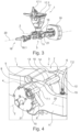
Figuren 4 und5 exemplarisch beschrieben wird. Wie man besonders aus derFigur 4 erkennen kann, weist die Kupplungskopfaufnahme 3 eine Gabelform mit zwei Gabeln 11, 12 auf, zwischen welchen der Kupplungskopf 1 aufgenommen ist. Jede Gabel 11, 12 umfasst eine Bohrung 7.1, 7.2, die gemeinsam eine zweite Führung 7 ausbilden. Die radial äußere Oberfläche eines Gehäuses 14 des Kupplungskopfes 1 bildet eine erste Führung 6 aus. Die Arretiervorrichtung 4 umfasst einen Steckbolzen 5, der in die erste Führung 6 im Kupplungskopf 1 und die zweite Führung 7 in der Kupplungskopfaufnahme 3 eingesteckt ist, wodurch der Kupplungskopf 1 in der Horizontalebene, das heißt in seiner aktiven Position, formschlüssig gegen Verdrehen um die Verschwenkachse 2 gesichert ist. - Der Steckbolzen 5 weist eine Längsachse 8 auf, um welche er im eingesteckten Zustand in die erste Führung 6 und die zweite Führung 7 verdrehbar ist. Der Steckbolzen 5 weist ferner einen Radialvorsprung 9, hier in Form eines Hebels auf, der im eingesteckten Zustand des Steckbolzens 5 in der ersten Führung 6 und der zweiten Führung 7 hinter eine Anschlagfläche 10 an der Kupplungskopfaufnahme verdreht werden kann, um ein Herausziehen des Steckbolzens 5 aus der ersten Führung 6 und der zweiten Führung 7 formschlüssig zu blockieren.
- Das Verdrehen des Steckbolzens 5 derart, dass der Radialvorsprung 9 hinter die Anschlagfläche 10 gelangt, ist bevorzugt allein durch die Gewichtskraft des Radialvorsprungs 9 möglich, sodass eine automatische Blockade nach dem Einstecken des Steckbolzens 5 in die erste Führung 6 und die zweite Führung 7 erfolgt. Hierfür weist die erste Führung 6 im Kupplungskopf 1 bevorzugt ein oder mehrere Druckstücke 15 auf, welche eine Kontaktfläche zwischen dem Kupplungskopf 1, hier dessen Gehäuse 14, und dem Steckbolzen 5 vergleichsweise reduzieren. Das oder die Druckstücke 15 können ferner eine reibungsreduzierende Oberfläche aufweisen.
- Im gezeigten Ausführungsbeispiel wird die erste Führung 6 durch eine Stufe 13 in der radial äußeren Oberfläche des Gehäuses 14 gebildet und es sind Druckstücke 15 in diese Stufe 13 eingesetzt, welche eine Anlage des Steckbolzens 5 in beide Verdrehrichtungen des Kupplungskopfes 1 um die Verschwenkachse 2 herstellen. Die Anlagefläche ist dabei auf weniger als die Hälfte der Breite des Gehäuses 14 zwischen den Gabel 11, 12 reduziert, bezogen auf jede Verschwenkrichtung.
- In den
Figur 1 bis 3 ist exemplarisch gezeigt, dass der Kupplungskopf 1 eine erste Kupplungseinrichtung 17 in Form einer Scharfenbergkupplung mit Kupplungskegel 17.1 und Kupplungstrichter 17.2 aufweist. Die Zugkupplung weist ferner eine zweite Kupplungseinrichtung 18 mit einer Zugöse 18.1 auf. Eine solche Zugöse 18.1 kann mit einem Zughaken eine Zugverbindung herstellen. - Die zweite Kupplungseinrichtung 18 kann insbesondere nur dann in die Horizontalebene, das heißt die Kupplungsebene, um die Verschwenkachse 2 verschwenkt werden, wenn sich der Kupplungskopf 1 in seiner in der
Figur 3 gezeigten inaktiven Position befindet. Gemäß einer Ausführungsform ist das Verschwenken der zweiten Kupplungseinrichtung 18 an das Verschwenken des Kupplungskopfs 1 zwangsgekoppelt, sodass der Kupplungskopf 1 und die zweite Kupplungseinrichtung 18 stets gemeinsam um die Verschwenkachse 2 verschwenkt werden. Wie in derFigur 2 gezeigt, kann jedoch auch ein separates Verschwenken des Kupplungskopfes 1 und der zweiten Kupplungseinrichtung 18 um die Verschwenkachse 2 vorgesehen sein. - Zum Verschwenken des Kupplungskopfes 1 um die Verschwenkachse 2 ist ein Antrieb 21 vorgesehen, der gemäß dem Ausführungsbeispiel in den
Figuren 1 bis 3 als Handkurbel ausgeführt ist und gemäß dem Ausführungsbeispiel in derFigur 4 als elektrischer, pneumatischer oder hydraulischer Antrieb. - Gemäß einem nicht näher dargestellten Ausführungsbeispiel kann der Kupplungskopf 1 auch ohne gesondertes Getriebe verschwenkt werden, beispielsweise von Hand, durch eine entsprechende manuelle Kraftausübung auf den Kupplungskopf 1.
- In der
Figur 5 ist exemplarisch dargestellt, dass die Kupplungskopfaufnahme 3 einen ersten Anschlag 22 aufweist, an welchem der Kupplungskopf 1, hier mit einem Kupplungskopfanschlag 23, anschlägt, wenn er aus seiner inaktiven Position in seine aktive Position verschwenkt wird und die aktive Position erreicht hat. In dieser Position fluchten die aus derFigur 4 ersichtlichen ersten und zweiten Führungen 6, 7 miteinander und der Steckbolzen 5 kann leicht in diese Führungen 6, 7 mit einem sehr kleinen Spiel eingesetzt werden. Entsprechend wird der Kupplungskopf 1 bei eingestecktem Steckbolzen 5 exakt in der Horizontalebene gehalten. - Im gezeigten Ausführungsbeispiel weist die Kupplungskopfaufnahme 3 einen zweiten Anschlag 24 auf, an welchem der Kupplungskopf 1, hier mit seinem Kupplungskopfanschlag 23, anschlägt, wenn der Kupplungskopf 1 in seine inaktive Position verdreht wird. Hier könnte eine entsprechende Arretiervorrichtung, beispielsweise mit Steckbolzen, vorgesehen sein, um den Kupplungskopf 1 formschlüssig in der inaktiven Position zu halten.
- Der erste Anschlag 22 könnte auch zusätzlich oder alternativ hinten, das heißt auf der der Kupplungskopfaufnahme 3 beziehungsweise der Zugstange 16 zugewandten Rückseite des Kupplungskopfes 1, und/oder unten an der Kupplungskopfaufnahme 3 beziehungsweise der Zugstange 16 vorgesehen sein, insbesondere als Gegenfläche zu einem Kupplungskopfanschlag 23 in Form einer von der radial äußeren Oberfläche des Gehäuses 14 wegstehenden Nase oder Vorsprung am Kupplungskopf 1, wobei der Kupplungskopfanschlag 23 am Kupplungskopf 1 dann von unten und/oder von vorne am ersten Anschlag 22 anschlägt, wenn sich der Kupplungskopf 1 in seiner aktiven Position befindet. In diesem Fall können der erste Anschlag 22 und der Kupplungskopfanschlag 23 bevorzugt zumindest im Wesentlichen mittig zwischen den Gabeln 11, 12 vorgesehen sein, während im gezeigten Ausführungsbeispiel bevorzugt beide Gabeln 11, 12 mit jeweils einem ersten Anschlag 22 versehen sind, an denen jeweils ein Kupplungskopfanschlag 23 anschlägt, um die Gewichtskraft des Kupplungskopfes 1 gleichmäßig aufzunehmen. Durch einen oder mehrere solche ersten Anschläge 22 können verklemmende Kräfte zwischen dem Steckbolzen 5 und der ersten und zweiten Führung 6,7 vermieden werden.
-
- 1
- Kupplungskopf
- 2
- Verschwenkachse
- 3
- Kupplungskopfaufnahme
- 4
- Arretiervorrichtung
- 5
- Steckbolzen
- 6
- erste Führung
- 7
- zweite Führung
- 7.1
- Bohrung
- 7.2
- Bohrung
- 8
- Längsachse
- 9
- Radialvorsprung
- 10
- Anschlagfläche
- 11
- Gabel
- 12
- Gabel
- 13
- Stufe
- 14
- Gehäuse
- 15
- Druckstück
- 16
- Zugstange
- 17
- erste Kupplungseinrichtung
- 17.1
- Kupplungskegel
- 17.2
- Kupplungstrichter
- 18
- zweite Kupplungseinrichtung
- 18.1
- Zugöse
- 19
- Wagenkasten
- 20
- Längsachse
- 21
- Antrieb
- 22
- erster Anschlag
- 23
- Kupplungskopfanschlag
- 24
- zweiter Anschlag
Claims (14)
- Zugkupplung mit einem Kupplungskopf (1), der verschwenkbar um eine horizontale Verschwenkachse (2) in einer Kupplungskopfaufnahme (3) gelagert ist, wobei der Kupplungskopf (1) zwischen einer aktiven Position, in welcher er zum Kuppeln mit einem gegengleichen Kupplungskopf innerhalb einer Horizontalebene ausgerichtet ist, und einer inaktiven Position, in welcher er aus der Horizontalebene heraus verschwenkt ist, um die horizontale Verschwenkachse (2) verschwenkbar ist; wobei eine Arretiervorrichtung (4) vorgesehen ist, mit welcher der Kupplungskopf (1) in der Horizontalebene arretierbar ist;
dadurch gekennzeichnet, dass
die Arretiervorrichtung (4) einen Steckbolzen (5) umfasst, der durch eine erste Führung (6) im Kupplungskopf (1) und eine zweite Führung (7) in der Kupplungskopfaufnahme (3) steckbar ist, um den Kupplungskopf (1) formschlüssig gegen Verdrehen um die Verschwenkachse (2) zu sichern. - Zugkupplung gemäß Anspruch 1, dadurch gekennzeichnet, dass die Kupplungskopfaufnahme (3) einen ersten Anschlag (22) aufweist, an welchem der Kupplungskopf (1) beim Verschwenken in die aktive Position anschlägt, sodass die erste Führung (6) und die zweite Führung (7) miteinander fluchten.
- Zugkupplung gemäß einem der Ansprüche 1 oder 2, dadurch gekennzeichnet, dass der Steckbolzen (5) im in die erste Führung (6) und die zweite Führung (7) eingesteckten Zustand innerhalb der ersten Führung (6) und der zweiten Führung (7) um seine Längsachse (8) verdrehbar ist und wenigstens einen Radialvorsprung (9) aufweist, der zur Ausbildung eines Hinterschnitts mit einer Anschlagfläche (10) an der Kupplungskopfaufnahme (3) mit dem Steckbolzen (5) verdrehbar ist, um ein Herausziehen des Steckbolzens (5) aus der ersten und zweiten Führung (6, 7) zu blockieren.
- Zugkupplung gemäß Anspruch 3, dadurch gekennzeichnet, dass der Radialvorsprung (9) als senkrecht oder winklig zur Längsachse (8) verlaufender Hebel ausgeführt ist.
- Zugkupplung gemäß einem der Ansprüche 3 oder 4, dadurch gekennzeichnet, dass sich die Anschlagfläche (10) in der aktiven Position des Kupplungskopfes (1) unterhalb der Längsachse (8) des Steckbolzens (5) erstreckt.
- Zugkupplung gemäß einem der Ansprüche 3 bis 5, dadurch gekennzeichnet, dass der Steckbolzen (5) im eingesteckten Zustand unter Aufbringung eines Drehmoments verdrehbar ist und der Radialvorsprung (9) eine Länge und ein Gewicht aufweist, die im eingesteckten Zustand des Steckbolzens (5) ein Antriebsmoment um die Längsachse (8) auf den Steckbolzen (5) ausüben, wobei das Antriebsmoment größer als das Drehmoment ist.
- Zugkupplung gemäß einem der Ansprüche 3 bis 6, dadurch gekennzeichnet, dass der Steckbolzen (5) nur in einer Drehposition um die Längsachse (8) in die erste und zweite Führung (6, 7) einsteckbar ist, in welcher der Radialvorsprung (9) mit einem Verdrehwinkel von weniger als 180°, insbesondere weniger als 135° oder 90°, gegenüber der Anschlagfläche (10) angeordnet ist und ferner gegenüber einer Vertikalebene auf der Seite der Anschlagfläche (10) angeordnet ist.
- Zugkupplung gemäß einem der Ansprüche 1 bis 7, dadurch gekennzeichnet, dass die Kupplungskopfaufnahme (3) eine Gabelform mit zwei Gabeln (11, 12) ausbildet, zwischen welchen der Kupplungskopf (1) aufgenommen ist, und jede Gabel (11, 12) eine Bohrung (7.1, 7.2) aufweist, die gemeinsam die zweite Führung (7) ausbilden.
- Zugkupplung gemäß einem der Ansprüche 1 bis 8, dadurch gekennzeichnet, dass die erste Führung (6) durch eine Stufe (13) in einer radial äußeren Oberfläche eines Gehäuses (14) des Kupplungskopfes (1) ausgebildet wird.
- Zugkupplung gemäß Anspruch 9, dadurch gekennzeichnet, dass in der Stufe (13) wenigstens ein Druckstück (15) vorgesehen ist, das eine Anlagefläche des Steckbolzens (5) in eine oder beide Drehrichtungen des Kupplungskopfes (1) um die Verschwenkachse (2) auf jeweils weniger als zwei Drittel oder die Hälfte eines gegenseitigen Abstands der Gabeln (11, 12) im Bereich des Steckbolzens (5) begrenzen.
- Zugkupplung gemäß Anspruch 10, dadurch gekennzeichnet, dass das wenigstens eine Druckstück (15) eine reibungsreduzierte Oberfläche aufweist.
- Zugkupplung gemäß einem der Ansprüche 1 bis 11, dadurch gekennzeichnet, dass die Kupplungskopfaufnahme (3) durch ein axiales Ende einer Zugstange (16) gebildet wird.
- Zugkupplung gemäß einem der Ansprüche 1 bis 12, dadurch gekennzeichnet, dass der Kupplungskopf (1) eine automatische Kupplungseinrichtung umfasst.
- Zugkupplung gemäß einem der Ansprüche 1 bis 13, dadurch gekennzeichnet, dass der Kupplungskopf (1) eine erste Kupplungseinrichtung (17) eines ersten Typs, insbesondere mit Kupplungsvorsprung und Kupplungsöffnung, wie Kupplungskegel (17.1) und Kupplungstrichter (17.2), aufweist und die Zugkupplung ferner eine zweite Kupplungseinrichtung (18) eines zweiten, vom ersten Typ abweichenden Typs, insbesondere mit Zugöse (18.1) oder Zughaken, aufweist, wobei die zweite Kupplungseinrichtung (18) bevorzugt in der inaktiven Position des Kupplungskopfes (1) innerhalb der Horizontalebene ausrichtbar oder ausgerichtet ist.
Applications Claiming Priority (1)
| Application Number | Priority Date | Filing Date | Title |
|---|---|---|---|
| DE102023126439 | 2023-09-28 |
Publications (1)
| Publication Number | Publication Date |
|---|---|
| EP4530151A1 true EP4530151A1 (de) | 2025-04-02 |
Family
ID=92909604
Family Applications (1)
| Application Number | Title | Priority Date | Filing Date |
|---|---|---|---|
| EP24202497.4A Pending EP4530151A1 (de) | 2023-09-28 | 2024-09-25 | Zugkuppell |
Country Status (2)
| Country | Link |
|---|---|
| EP (1) | EP4530151A1 (de) |
| DE (1) | DE102024128024A1 (de) |
Citations (6)
| Publication number | Priority date | Publication date | Assignee | Title |
|---|---|---|---|---|
| FR352941A (fr) * | 1904-05-19 | 1905-08-28 | Krupp Ag | Dispositif de fixation de la tete d'attelage pivotante dans les attelages dits "de passage" pour voitures de chemins de fer |
| US1076912A (en) * | 1910-11-11 | 1913-10-28 | Gould Coupler Co | Draft-gear for railway-cars. |
| EP1055580B1 (de) * | 1999-05-27 | 2005-12-28 | William Cook Cast Products Limited | Kupplungen |
| CN205524288U (zh) * | 2016-03-31 | 2016-08-31 | 陕西海舵铁路科技发展有限公司 | 一种用于铁路车辆双作用的车钩 |
| EP3590784A1 (de) | 2018-07-04 | 2020-01-08 | Voith Patent GmbH | Zugstange für eine kupplung sowie entsprechende kupplung |
| WO2021185497A1 (de) | 2020-03-20 | 2021-09-23 | Voith Patent Gmbh | Kupplungsanordnung |
-
2024
- 2024-09-25 EP EP24202497.4A patent/EP4530151A1/de active Pending
- 2024-09-27 DE DE102024128024.7A patent/DE102024128024A1/de active Pending
Patent Citations (6)
| Publication number | Priority date | Publication date | Assignee | Title |
|---|---|---|---|---|
| FR352941A (fr) * | 1904-05-19 | 1905-08-28 | Krupp Ag | Dispositif de fixation de la tete d'attelage pivotante dans les attelages dits "de passage" pour voitures de chemins de fer |
| US1076912A (en) * | 1910-11-11 | 1913-10-28 | Gould Coupler Co | Draft-gear for railway-cars. |
| EP1055580B1 (de) * | 1999-05-27 | 2005-12-28 | William Cook Cast Products Limited | Kupplungen |
| CN205524288U (zh) * | 2016-03-31 | 2016-08-31 | 陕西海舵铁路科技发展有限公司 | 一种用于铁路车辆双作用的车钩 |
| EP3590784A1 (de) | 2018-07-04 | 2020-01-08 | Voith Patent GmbH | Zugstange für eine kupplung sowie entsprechende kupplung |
| WO2021185497A1 (de) | 2020-03-20 | 2021-09-23 | Voith Patent Gmbh | Kupplungsanordnung |
Also Published As
| Publication number | Publication date |
|---|---|
| DE102024128024A1 (de) | 2025-04-03 |
Similar Documents
| Publication | Publication Date | Title |
|---|---|---|
| AT511066B1 (de) | Befestigungsvorrichtung zum befestigen einer frontblende an einer schublade | |
| DE102007016822B4 (de) | Gestängekupplung mit Zapfen | |
| EP1985518A1 (de) | Automatische Knickkupplung | |
| DE4235780C1 (de) | ||
| DE112016004253T5 (de) | Schlosskörper | |
| EP2036421B1 (de) | Vorrichtung zum Kuppeln einer Gelenkwelle mit einer Zapfwelle eines Traktors | |
| EP3277899B1 (de) | Türgriffanordnung für ein kraftfahrzeug | |
| DE19636594A1 (de) | Löseeinheit | |
| EP0455251A2 (de) | Abnehmbare Anhängerkupplung | |
| EP2181868B1 (de) | Anhängekupplung | |
| DE102015224949B4 (de) | Kupplungsvorrichtung für eine lösbare Steckerverbindung zwischen einer Schleppantenne und einem Wasserfahrzeug | |
| DE102024128024A1 (de) | Zugkupplung | |
| EP1458938B1 (de) | Frontlader mit einer automatischen kupplungsvorrichtung | |
| DE102023127874A1 (de) | Zugkupplung | |
| DE102023131224A1 (de) | Automatische Zugkupplung | |
| EP1790504A1 (de) | Antriebseinheit für eine Anhängerkupplung | |
| DE102019106613B4 (de) | Verbindungsvorrichtung | |
| EP2444261B1 (de) | Kupplungssystem für Anbaugeräte an ein Mehrzweckfahrzeug | |
| DE102010000785B4 (de) | Anhängekupplungen | |
| DE10151382B4 (de) | Anhängevorrichtung | |
| DE102014223694B4 (de) | Halterung für ein Schließelement | |
| DE102006043430B4 (de) | Verriegelung für eine Anhängerkupplung | |
| EP3851588B1 (de) | Schnellwechsler | |
| DE102004017004B4 (de) | Angiographisches injektionssystem | |
| EP4624297A1 (de) | Zugkupplung |
Legal Events
| Date | Code | Title | Description |
|---|---|---|---|
| PUAI | Public reference made under article 153(3) epc to a published international application that has entered the european phase |
Free format text: ORIGINAL CODE: 0009012 |
|
| STAA | Information on the status of an ep patent application or granted ep patent |
Free format text: STATUS: THE APPLICATION HAS BEEN PUBLISHED |
|
| AK | Designated contracting states |
Kind code of ref document: A1 Designated state(s): AL AT BE BG CH CY CZ DE DK EE ES FI FR GB GR HR HU IE IS IT LI LT LU LV MC ME MK MT NL NO PL PT RO RS SE SI SK SM TR |
|
| STAA | Information on the status of an ep patent application or granted ep patent |
Free format text: STATUS: REQUEST FOR EXAMINATION WAS MADE |
|
| 17P | Request for examination filed |
Effective date: 20251002 |